Author Archives: paynterf

Robot Remodel Results

03/15/15 – The ides of March!

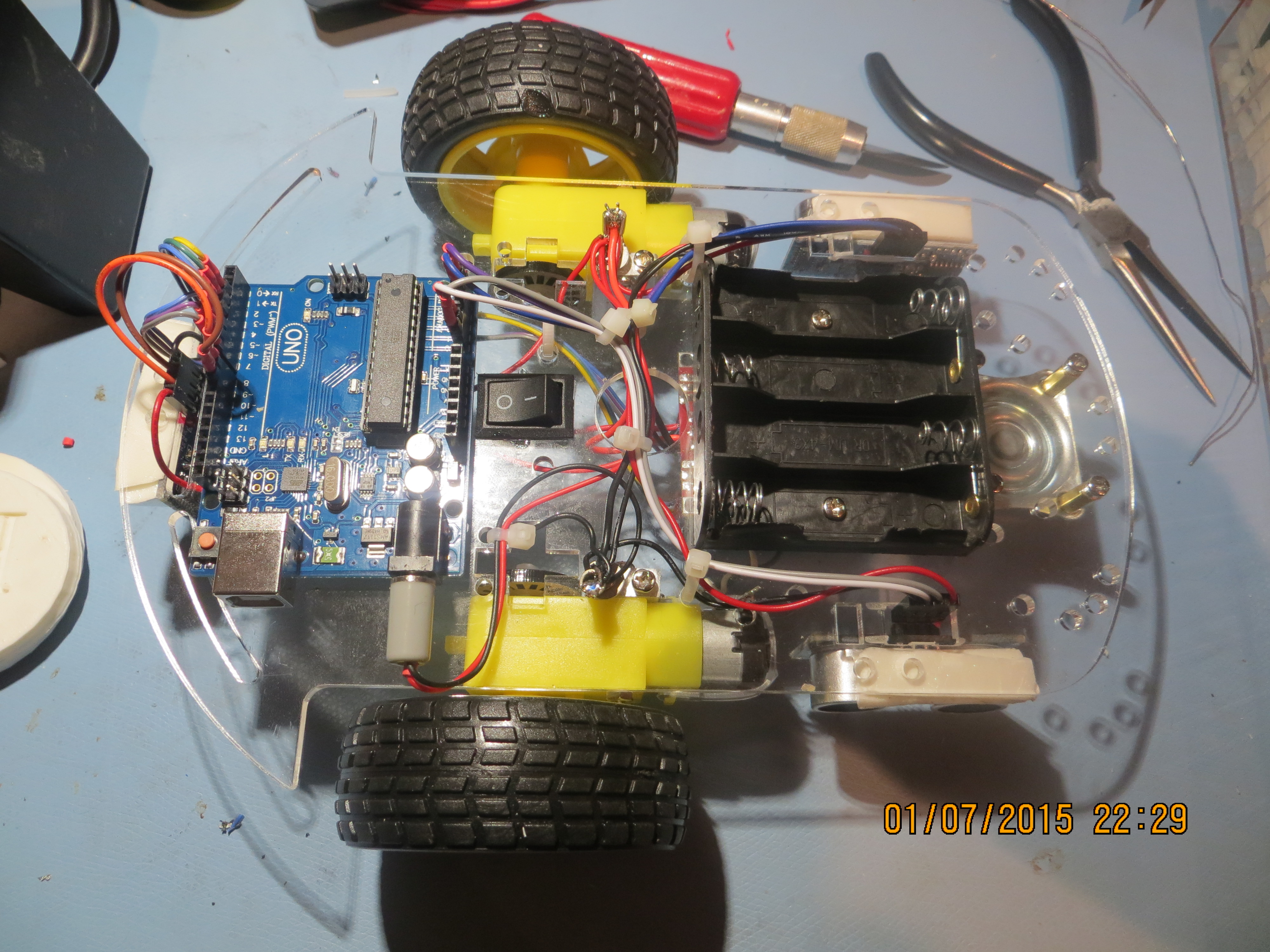
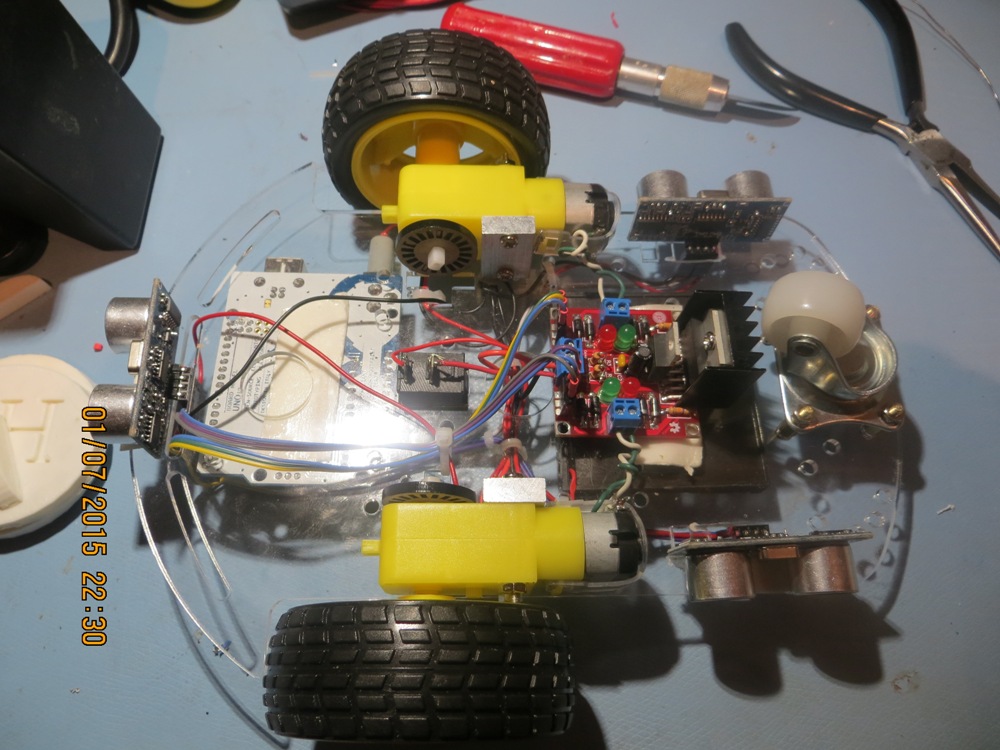
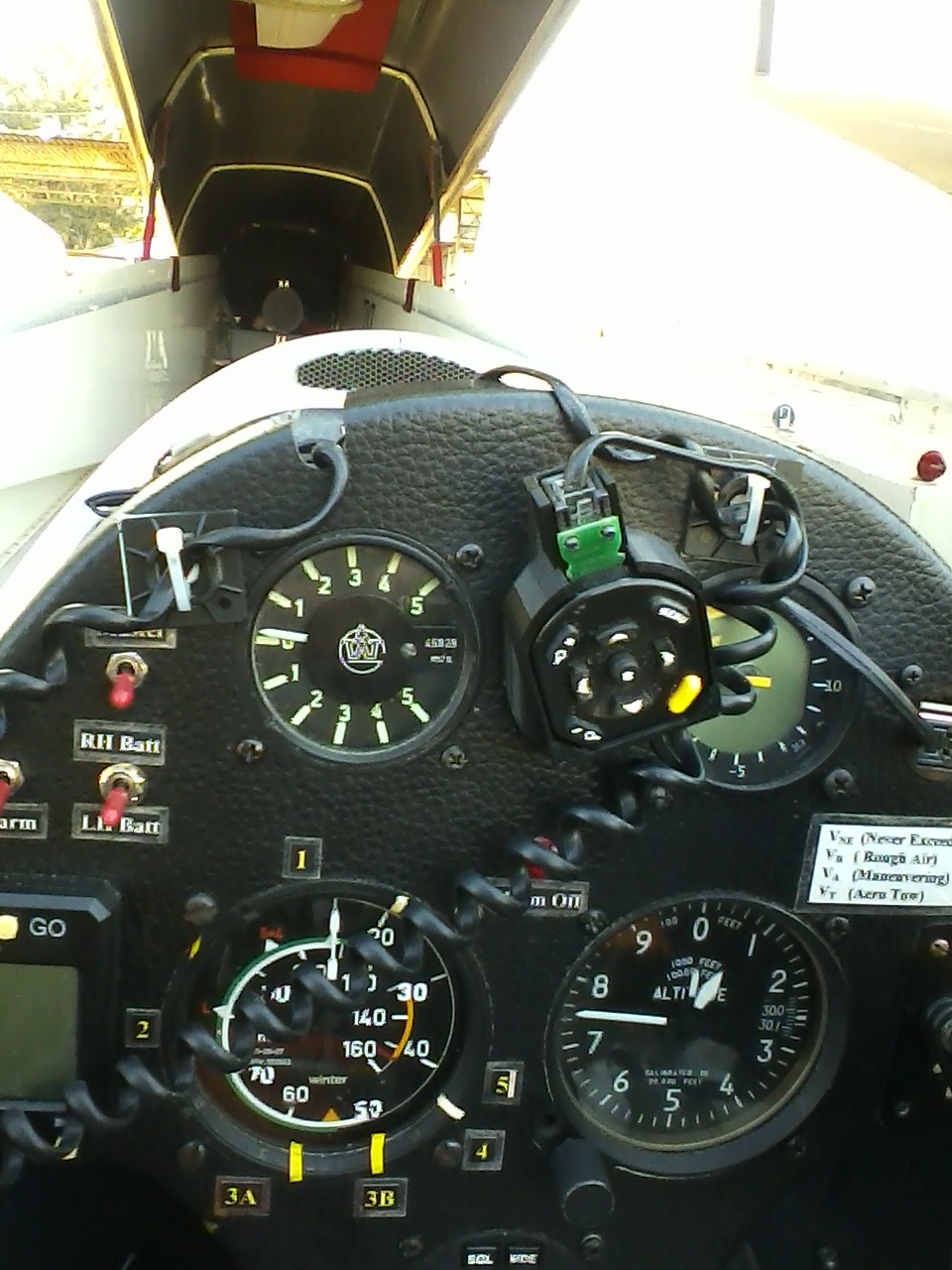
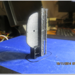
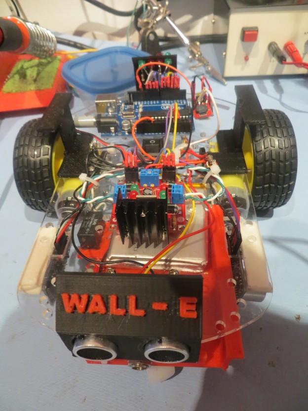
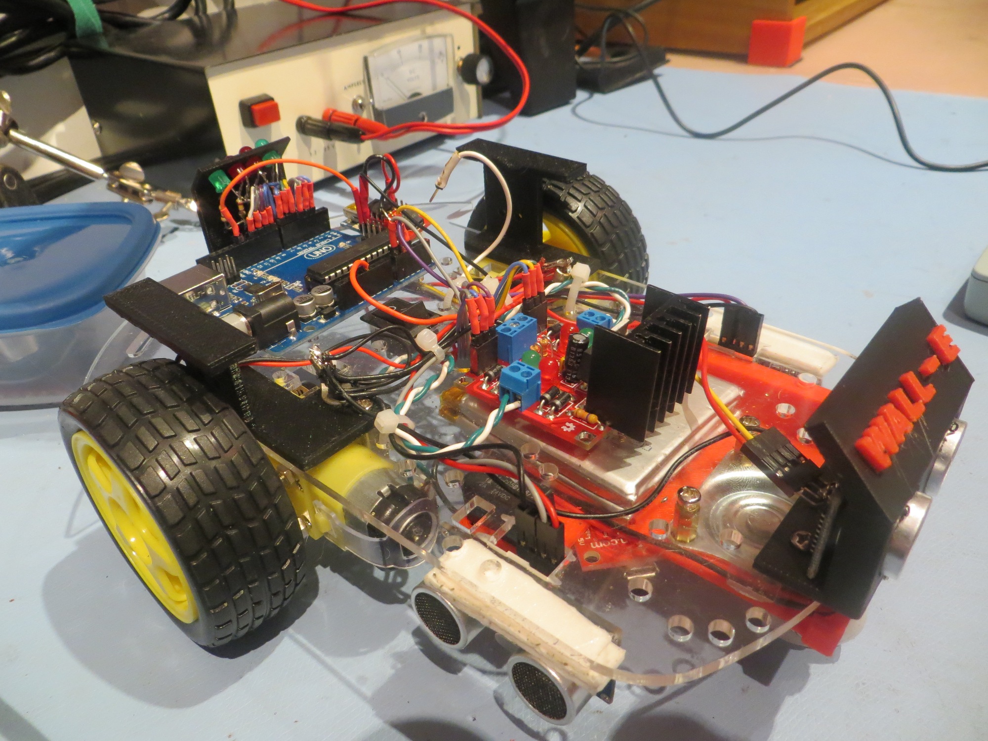
It’s been a while since I’ve posted on the progress of our wall-following robot project.  The last post talked about some significant remodeling goals, and most of those have been accomplished.  The 4 AA batteries have been replaced by 2ea Sparkfun 3.7V 2000mAH Li-ion batteries, the motor driver board was moved to the top of the robot platform, and the front ping sensor was installed on the ‘new front’ (remember, I turned the robot around when I discovered the side-mounted ping sensors were causing regenerative feedback?).  However, I didn’t install the two additional side-mounted ping sensors as planned – at least not yet.  Here are some photos of the remodeled robot.

Wall-E Overall View

Wall-E Overall View

Wall-E Front View

Wall-E Front View

Adafruit Trinket auxiliary Morse code processor

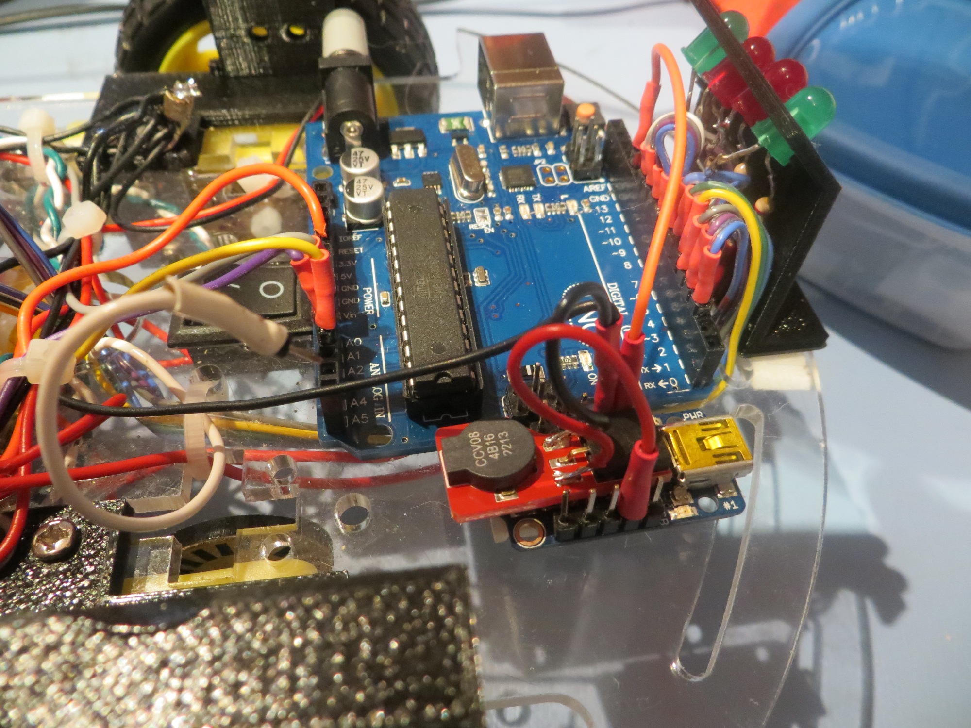
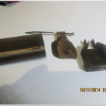
Adafruit Trinket auxiliary Morse code processor.  This is how Wall-E yells for food 😉

Battery Pack Front View, showing charging jack

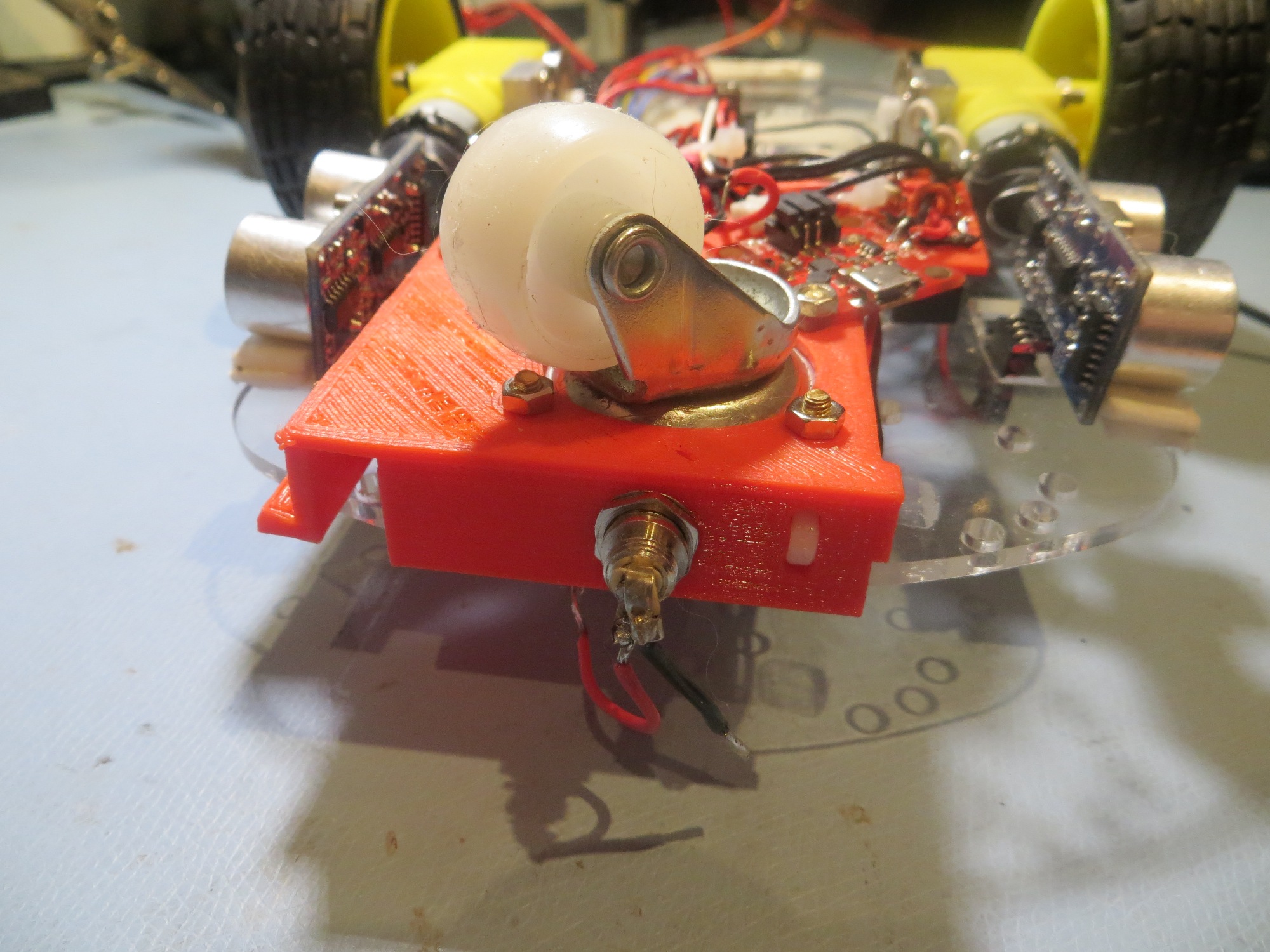
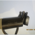
Battery Pack Bracket Front View, showing charging jack

Battery Pack Bracket Bottom View

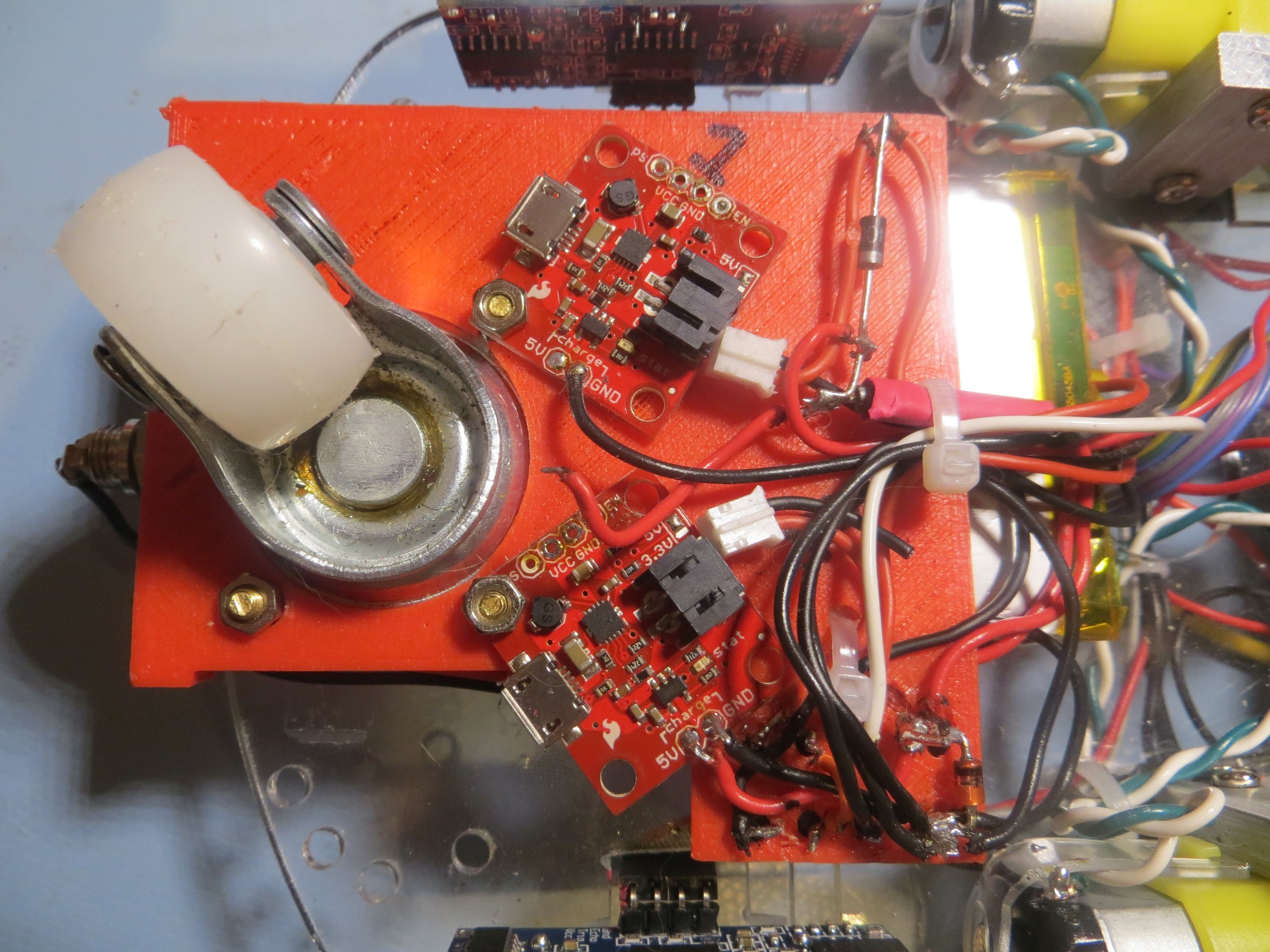
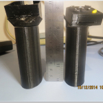
Battery Pack Bracket Bottom View, showing the two Sparkfun PowerCell Li-ion battery chargers.

One significant change that came out of the remodeling effort was the decision to abandon the idea of having Wall-E recharge itself.  It was pretty clear from results so far that getting Wall-E into a precise enough position/orientation to engage a charging plug was going to be  very difficult, even with some sort of guide-in rails.  Plus there was the problem of getting Wall-E disengaged and going again at the end of the charging cycle.  So, a new plan was hatched to have Wall-E ‘yell for food’ with some sort of audible signal.  Since I’m an ex-Ham Radio operator, I immediately thought of adding a Morse code capability to the robot, and it turned out Danny was interested in Morse code too, so… Now all we had to do was figure out how to get Wall-E to speak Morse, along with everything else it was doing.  Our first try at this used Arduino’s non-blocking  tone(pin, frequency, duration) function to generate the dots and dashes, but it turned out the duration of each tone wasn’t anywhere near accurate enough for this.  Wall-E sounded like a very drunk radio operator with dots sounding like dashes and dashes running on forever.  The solution to this was to change to the  blocking version of tone(pin, frequency)/noTone(pin), but this meant Wall-E couldn’t be moving while sending Morse – bummer!  As it turned out though, I had been playing around with Adafruit’s Trinket microprocessor  as a possible replacement for the Arduino Micro in our Enders Game Flashgun project, so I decided to try and use a Trinket as an auxiliary Morse code processor.  After the normal amount of muttering and teeth-gnashing, the Trinket, along with a Sparkfun RedBot Buzzer  wound up working pretty well! +Vbatt for the Trinket is supplied through one of the Arduino’s digital I/O pins; when the Arduino senses that the battery voltage is getting too low, it simply powers up the Trinket and parties on, and the Trinket does the ‘Yell for food’ stuff independently.

After re-installing the front ping sensor on the new front end of the robot, I had to decide how to sense the ‘stuck’ condition.  Originally I was doing this by detecting the condition where sequential front ping distances were identical – i.e. the robot wasn’t moving (at least not in the forward direction).  This worked, but there were problems.  First, I had to exclude ping distances of zero, as zero is also returned when the ping distance is greater than the maximum (200cm in my case).  This meant that if Wall-E got stuck with it’s snout right up against an obstacle, the  real distance could be zero, and then the ‘stuck’ condition would never be detected.  In addition, there was the problem of integer truncation int the ping distance return value from ping().  If Wall-E is moving slow enough, or the pings happen fast enough, then two identical distance values could happen naturally – oops!  I could address the adjacent ping/speed issue by spacing out the front distance checks in time so that any reasonable robot speed would produce at least 1cm travel, but there didn’t appear to be any way to address the real-zero-distance problem.  So, I decided to change the ‘stuck’ detection logic to simply declare ‘stuck’ whenever Wall-E got within some minimum distance (10cm to start) of an obstacle. This turned out to be  much simpler to implement, more robust, and maybe even extensible to more complex situations in the future.

After running some wall-following and obstacle avoidance trials (see first movie below), it appeared that Wall-E was doing so well that it might be time to try a ‘tail trial’ or two to see what the cats thought of a mobile prey animal.  Turned out that Yori (the outgoing cat) was right on top (literally) of the situation, but Sunny (the wall-flower cat) ignored the whole thing – see the second movie below.

Future Work:

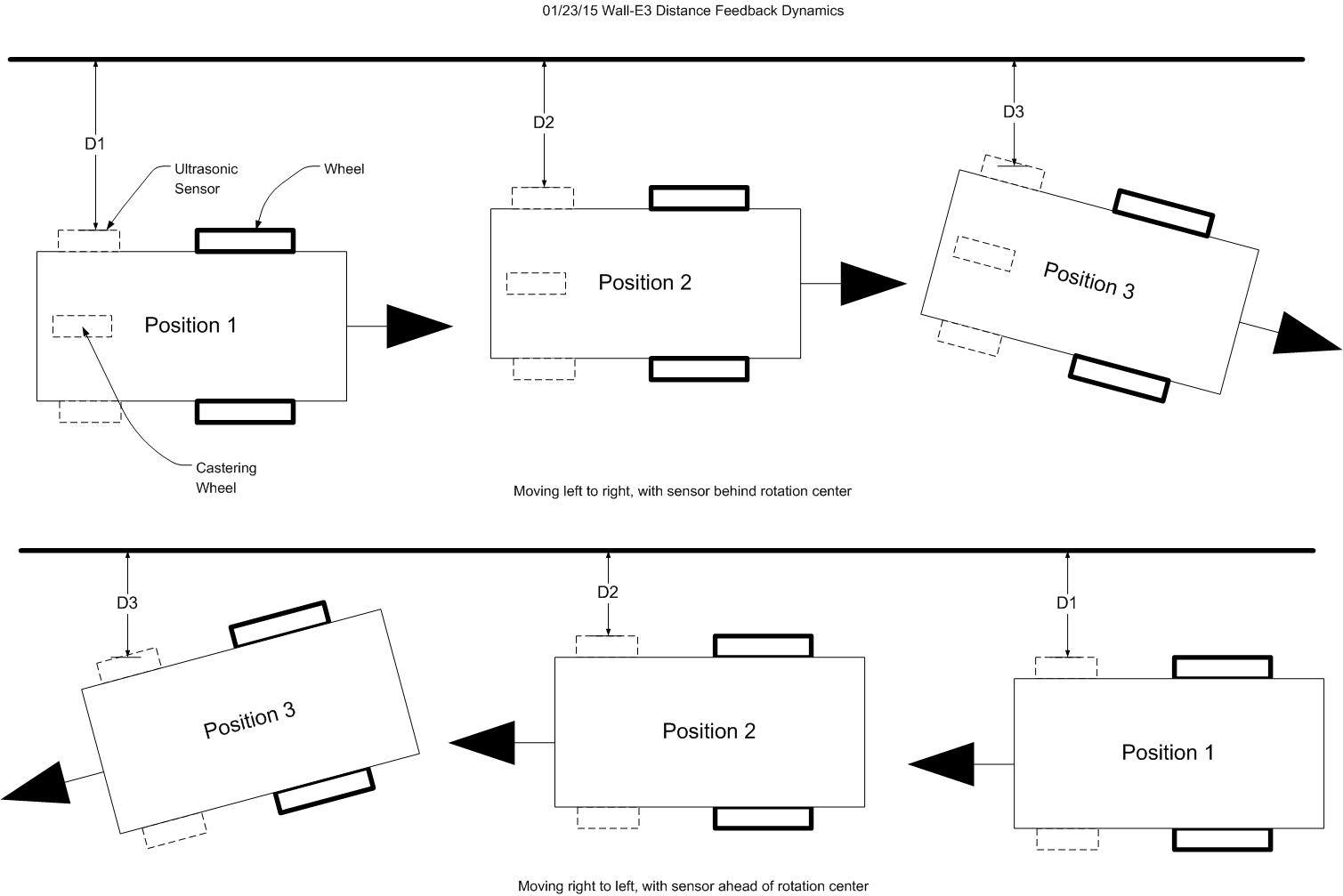
One of the things I noted from recent runs is that Wall-E will occasionally break out of wall-following mode and nose-dive into the nearest wall.  After seeing this happen a number of times, I’m beginning to believe this is another unintended consequence of having the side ping sensors so far ahead of the axis of rotation.  When first we visited this saga, I had just discovered that the side ping sensor placement  behind  the center of rotation was setting up  a regenerative feedback loop that caused Wall-E to over-correct wildly.  Moving the sensors  ahead of the axis of rotation (actually what I did was simply redefine  Wall-E’s ‘front’ and ‘back’) changed the feedback loop from regenerative to degenerative allowing Wall-E to successfully follow walls.  However, it turns out that this ‘fix’ isn’t quite as clean as I had thought.  For the first few degrees of rotation around the axis, the near-side ping sensor moves directly toward the wall, giving the required negative feedback.  However, if the rotation goes beyond about 30 degrees, then the distance returned  by the near-side ping sensor may start to go back up, as the point on the wall pointed to by the ping sensor moves away from the perpendicular.  I speculate this acts like a variable phase shift, and at some point it shifts enough so the loop feedback sign changes – oops!  The fix for this is to either move the left/right ping sensors nearer to the axis of rotation and/or incorporate additional left/right sensors at the axis of rotation to provide a distance term that doesn’t change significantly with robot rotation.

Another thing that I saw from this last round of trials is that I need to add some wheel covers to Wall-E, to prevent the wheels from hanging up on chair legs.  Not quite sure how to do this yet, but…


Robot Remodel

02/20/15

Between the last post almost a month ago, the wall-following robot has undergone some significant changes to address deficiencies identified in January

  • First and foremost – the use of 4ea AA batteries for power.  The plan is to replace this pack with 2ea 3.7V 2000mAH Li-ion batteries from Sparkfun, charged via 2ea Sparkfun PowerCell chargers.  Moreover, these will be moved to the bottom of the robot rather than sitting on top.  This required a custom-designed bracket to hold the batteries and chargers, but that’s no problemo with  my new PowerSpec PRO 3-D printer (well, actually it *was* a problemo, as it took about 6 revisions to get the bracket optimized).
  • The current motor driver module is located on the underside of the robot, and its heatsink barely clears the floor.  In fact it started dragging the floor on some of the later tests last month, as the double-sided foam tape holding it up began to sag.  The plan is to move this unit to the top, into the space vacated by the clunky AA pack.
  • More ping sensors:  The old unit had 3 – 2 side-looking and one forward-looking.  After figuring out the positive feedback problem in the original configuration and turning the unit around, it had 2 side-looking and one rear-looking sensor, so that obviously has to change.  In addition to moving the rear sensor to the front, I want to add two additional side-looking sensors directly over the main wheels so they don’t suffer the ‘swing’ effect due to the long moment arm from the turn center to the sensor.  My hope is by combining the information from the on-axis and off-axis side-looking sensors, I can improve Wall-E’s wall-following performance.


Here are some preliminary movies – enjoy!


More Wall-following Robot Tuning

01/26/15

Yesterday and today I have been working through some ‘issues’ with the wall-following robot. The darned thing  insists on doing exactly what I tell it to do, rather than what I  want it to, despite the liberal use of the RPM (Read Programmer’s Mind) command throughout the code.  This time I had managed to make modifications to the left & right motor speeds in two different locations (instead of encapsulating all changes in one function), and used value/copy arguments instead of reference arguments in one place where refs were absolutely necessary.

Anyway, I got the ‘issues’ squared away, and then decided to make some ‘improvements’ (never   a good thing!) by changing the distance acquisition code to use the NewPing library’s ‘ping_median()’ function.  The ping_median() function makes a number (5 by default) of pings in quick succession and then ( after throwing out any out-of-range values) returns the median distance.  I  thought this might smooth things out a bit, but what it actually did was slow things down sufficiently so the robot quickly got outside the loop capture range and departed the area.  One change that actually did improve things was to add some code in setup() to start the robot moving straight  at low speed after acquiring an initial distance estimate (I did use the ping_median() function for this), as this reduced/eliminated startup divergences.


After making these changes, I ran some more wall-following tests, with some interesting results.  On one test the robot ran off the end of the straight-wall test section (aka ‘Kitchen’) and onto the rug in our living room.  On the rug sits a footstool with a round base. Watch the action :-).


So, at this point the robot is doing a fair job of following walls, although it still has a number of deficiencies that have to be addressed  before it gets let loose in the wild to roam the hallways.

  • Gaps give it fits.  There is a gap of about 10-12cm between the fridge and the pantry wall in the kitchen, and when the robot gets to this spot, it invariably nose-dives right into it, as the distance measurement instantly increases  a lot right there.  I don’t really know if anything can be done about this, as this same behavior is what allows it to follow wall variations in the first place.
  • After reversing the definition of ‘forward’ on the robot (see my earlier post), the ‘front’ ping sensor is actually mounted on the new ‘rear’.  I still need to reposition it (or make that end the front again).  I’m thinking seriously of repositioning the left and right ping sensors so they are on or near the line between wheel axles, to suppress/eliminate the mechanical element of the feedback the wall-following feedback loop.  If I do that, then I can turn the robot around again, and not have to reposition the ‘front’ sensor.
  • It still runs on non-rechargeable AA alkalyne batteries (I’ve got rechargeables on the way, but…).  Even when I get rechargeables installed, I still have to figure out how to get the robot to charge itself.

Stay tuned! 😉


Tuning the Robot’s Wall-following Feedback Loop

01/25/15 10:00

After getting the robot to follow a wall  at all, I have now graduated to the task of tuning the feedback loop for ‘best performance’.  Part of the problem is trying to define what ‘best performance’ means in terms of wall following capabilities.

In my UpdateWallFollowMotorSpeeds() function, I compare the current distance to the previous one, and adjust left/right motor speeds up or down to  turn away from the wall if the distance is decreasing, or toward it if the distance is increasing.  The amount of adjustment applied is a program constant that can be ‘tuned’ for optimum performance, whatever that means.  Wheel speeds can vary from 50 to 200 (out of a 0 to 255 range)

  • Small wheel-speed adjustment values result in a smooth  sinusoidal path with a slowly increasing amplitude – which eventually diverges to the point where the robot either departs from the wall entirely, or runs into it head-on, as shown in the following video, taken with an adjustment value of 5
  • Larger adjustment values increase the ‘available control authority’, but also increases the correction magnitude to the point where a small error in distance measurement causes the robot to diverge and spin in place.
  • An intermediate value of 25 seem to be a good compromise between smoothness and sufficient control authority to keep the robot going straight (on average, anyway)

Speed Adjustment Value = 5


Speed Adjustment Value = 50


Speed Adjustment Value = 25.  On this video you can also see the two green LED’s which serve as ‘commanding left turn’ and ‘commanding right turn’ debug indicators.

This is OK, but still not quite what I want for my wall following robot.  However, it may well be that I will never be able to completely suppress the oscillations, as this is a fairly complex feedback loop.  And, as I know from my 40+ years as an Electrical Engineer, all feedback loops can cause oscillations when the loop phase shift approaches 180 degrees.  This particular arrangement has both electrical and mechanical phase terms that make it even more interesting

  • The position of the sensors relative to the axis of rotation introduces a large phase shift term, as small rotation changes cause large distance changes. As we saw earlier, the original phase relationship with the sensors at the rear was positive (a small turn toward the wall causes a large increase in distance measurement, exactly opposite of the expected result), while the phase relationship in the current configuration with the sensors at the front is negative   (a small turn toward the wall causes a large    decrease in distance measurement, the expected result but amplified).
  • There is a time/phase lag between the time the program makes a decision to the time the wheel speeds actually change, so by the time the robot starts to compensate for an error term, the error has had time to get larger.  This in turn means the robot will continue to correct well past the point where it should, leading to overshoot in the other direction.

The above leads me to believe that I (aka the robot) should be making corrections based on the value of  the distance-vs-time curve slope, rather than  just the sign of the slope (positive or negative).  If I use the value of the slope, then I can make bigger corrections for larger slopes, and smaller ones for smaller slopes.  This could get a little tricky, as the slope calculation  requires some knowledge of time; IOW, each point in the curve is a (dist,time) pair, and both have to be known to calculate the slope between two pairs (dist0,time0) and (dist1,time1).  I could simply assume that the time between distance measurements is a constant, which would mean that the slope is proportional to  (dist1 – dist0).  So, I think I’ll try a very simple setup, and make the adjustment value = 25 * |d1-d0|.


The ‘Robot Weave’ (aka Wall-E3)

01/23/2015

In our last installment, Wall-E2 was more a wall-bumping robot than a wall-following one, and since then I have beating my own head against a wall trying to figure out why the darned thing wouldn’t behave the way I expected.

The basic idea of our wall-following robot is to use a side-looking ultrasound distance sensor to maintain a constant distance from a wall.  If the distance readings start to increase, the outside motor would be sped up, and the inside one slowed down, until the readings started going down again, at which point the procedure would be reversed.  If the distance readings remained constant, no speed adjustments would be made.  Debugging this arrangement is difficult, because it is hard to obtain any real-time data on what the robot is seeing and doing.  The Uno doesn’t have much RAM, so storing test data for later analysis isn’t feasible, and besides, I’d wind up spending more time on the analysis software than on the robot itself.  I was able to run the robot tethered to my PC in Visual Micro’s serial debug mode, and this (eventually) allowed me to gain some small insight into what was going on.  I finally decided that  I had too many moving parts (some virtual, some literal) and I was going to have to drastically simplify the system if I wanted to have any chance of making progress.  So, I removed all the control code except that required to go straight and follow the wall – non-essential stuff like the back-up-and-turn feature was all commented out.  Then I added two  sets of  Red/Green LED pairs to the Uno as slow/fast indicators for the left and right motors.  Green meant the motor was slowing down, and red meant it was speeding up.  The idea was to allow me to (literally) see if the commands to the motors were consistent with the robot’s position relative to the wall.

I was testing each revision by holding the robot in my hand and moving it back and forth toward one wall of my lab area, while watching the distance and motor speed debug readouts on my PC.  If the desk testing went well, then I would run the robot untethered along a section of wall in our kitchen.  This was very frustrating because it looked like the robot behaved properly on the desktop tests, but not on the real-world wall testing – how could this be?  In test after test, the robot literally spun out of control almost immediately, winding up with one wheel running full speed  and the other one stopped.

Eventually out of desperation I ran multiple wall tests, each time starting with the robot parallel to my test wall, hoping to see why it  always corrected in the wrong direction on the wall, but in the right direction in the desktop tests.  I saw that the robot made an initial turn away from the wall – OK, but then instead of turning back toward it – kept turning even sharper away from it – again and again!  I watched several times very carefully, trying to make my mind work like the robot’s simple program – get the distance, compare to the last one, adjust motor speeds to compensate.  And then it dawned on me – the robot was doing  exactly  what it was programmed to do, but the geometric relationship between the sensor location (where the distance measurement occurs) and the center of rotation of the robot was screwing up the phase relationships – turning what should have been a negative feedback loop into a positive one – with predictable results.  The following figure illustrates the problem.

Wall-E3 Distance Feedback Dynamics

Wall-E3 Distance Feedback Dynamics

In the figure, the top half illustrates the sensor and drive wheel layout, and shows the direction of travel as initially designed and programmed.  D1, D2, and D3 are successive distance measurements processed by the program.  At Position 2, the robot has determined that it needs to move away from the wall, and so speeds up the left motor and slows down the right motor, leading to Position 3.  However, because the sensor position is well behind the center of rotation (essentially the wheel axle line), the sensor actually gets closer to the wall instead of farther away. The robot responds to this by further increasing the left wheel speed and further decreasing the right wheel speed, which makes the problem even worse, etc.  This continues until the left motor is running full speed and the right motor is stopped, causing the robot to spin in place.

The bottom half of the figure shows my rather elegant (if I do say so myself) solution to this problem – simply reverse the direction of travel, which has the effect of converting the dynamics from positive to negative feedback.   Position 1 and Position 2 are the same as the top half, but in Position 3, it is clear that the distance from the wall starts increasing as soon as the robot starts rotating.  The robot responds by undoing its previous adjustments to the drive wheels; if it overshoots, the sensor dynamics bring it back to the centerline.

Implementing this scheme required very little work.  I had to swap the left and right distance sensor and motor control leads on the Uno (easier to do it this way than to change the code), and redefine ‘forward’ to be toward the caster wheel instead of away from it.  After making the above changes, I ran the wall-following test again, and lo and behold – it worked (sort of)!  The following video clip shows the new-improved Wall-E3 ‘weave’.


Now that I have the robot working to the degree that it doesn’t immediately spin out of control, I can start to look for ways to improve performance, to maybe reduce the amplitude of the ‘weave’ to something reasonable.  I have already incorporated the ‘NewPing‘ library (and contributed a few buckazoids to the author for a nice, elegent class library!) into the code, so I should be able to use it to speed things up.

Stay tuned for further adventures of Wall-E, the wall-following robot!


01/24/2015 – Update to the ‘Robot Weave’ saga:  I cleaned up the code a bit and hopefully sped things up a little.  The following video was taken in our kitchen a few minutes ago

Wall-following Robot (aka Wall-E2)

My grandson Danny and I have been working on a wall-following robot project, just for grins.  The general idea is to create a semi-autonomous robot as animated prey for our two cats.  I’m not sure I really care too much whether or not we ever get something the cats will actually run  toward instead of  away from; it’s the adventure that counts ;-).  There is also the hope that the robot adventure will (or can be made to) intersect/overlap with my  3D printing capabilities/interests.

Because I’m an old broke-down engineer, I have tried to imagine the general  requirements for our semi-autonomous prey robot.  So far as we have been able to enumerate them to date, they are:

  • Follow walls and not get stuck
  • Find and utilize a recharging station
  • Act like a cat prey animal (i.e. a mouse or similar creature)
  • Generate lots of fun and waste lots of time for the humans (me and my grandson) involved

The  first  three requirements actually seem pretty complete, although maybe not that easy to realize.  However, the fourth requirement should be easy to meet, and in fact I can report that it has already been partially achieved (we have already wasted lots of time and had lots of fun!)

To get started, I did what I always do – research!!  In the bad old days I did this by raiding technical libraries for books/magazines/articles relevant to the subject, and then going after everything referenced in the first round of material.  It wasn’t unusual for me to go through dozens or even hundreds of citations in a short period, after which I was usually able to create an effective approach to the challenge, whatever it was.  These days I start by throwing out a wide search loop on Google, and then following whatever trails seem productive.  At this stage I’m not at all picky about what I look at, and not at all picky about discarding materials or leads that weren’t  relevant.

In the case of DIY robots, there is a  lot of educational material out there, along with lots of DIY parts, development tools, and other goodies.  For our  first try at this, I acquired the following parts:

  • A Chinese Arduino Uno clone (http://www.ebay.com/itm/US-UNO-R3-ATmega328P-ATmega16U2-2012-Version-Board-Free-USB-Cable-for-Arduino-/251459710321?ssPageName=ADME:X:RRIRTB:US:3160), $8.99 ea.  I purchased 3 and was glad I did, as one arrived DOA (I got a full refund – thanks!), and I almost always manage to kill at least one of everything I try ;-).
  • A DIY robot chassis with a dual-motor L298 controller (http://www.ebay.com/itm/161246592134) for $24.99.  This turned out to be  way huge for a ‘cat prey animal’, but hey – ya gotta start from somewhere! ;-).
  • 5ea HC-SR04 Ultrasonic distance sensors.  Prices for these varied all over the lot, from almost $10 each to $6.14 for a pack of 5 (guess which one I picked).
  • A Solarbotics L298 Motor Driver kit from the local Micro Center, to replace the one that came with the robot chassis – the one I burned up shortly after it arrived 🙁
  • A set of 5ea Linear Technology LT3081 1.5A programmable voltage regulators, to replace the 2N3055/LM317t – based home-brew lab power supply I managed to burn up while burning up the dual motor driver 🙁  :-(.

While waiting for the parts to arrive, I worked on setting up the development environment for Arduino coding.  I already had VS2008 on my machine, so I utilized Visual Micro’s integrated IDE add-on for Arduino development, and found Virtronic’s very nice Simulator for Arduino – PRO version (www.virtronics.com.au).  Danny and I worked out the basic structure diagram, and we were able to get an early version of the software running on the simulator during a 3-4 day visit to the kid/grandkid abode over Christmas

First-cut structure chart for the wall-following robot

First-cut structure chart for the wall-following robot


After getting the parts in and assembling the robot chassis (and burning up/replacing the motor driver), I was able to get the robot to the ‘first baby steps’ stage fairly quickly (where the term ‘quickly’ is used somewhat loosely!)

Robot kit as delivered

Robot kit as delivered

Finished robot - top

Finished robot – top

Finished robot - bottom

Finished robot – bottom

And speaking of ‘baby steps’ – here is a short movie of the first really successful run of the wall-follower.  In this case, ‘success’ means that the robot recognized that it was stuck, and backed up/turned to recover from the stuck condition.

There’s lots more work to do before this particular robot has any chance of attracting a cat or two.  It doesn’t run in a straight line for crap, and is much better at bumping into walls than following them.  But hey, it is already over-achieving on technical requirement #4 (generate fun, waste time!) 😉

Stay tuned!


The Evolution of an Outside Shot

So, in order to not get beat up under the basket, I must have a  reliable  outside shot.  I never needed an outside shot before, as I was always the guy banging around under the basket.  Now that I’m old and feeble,  this  is a real good  way to get hurt (ask me how I know).  In the good old days, I might get bruised up in a game, but would be ready to do it again the next day.  Now if I get bruised up, it might be several  weeks before I can play again!  I can remember remarking to my wife that “I can tell I’m getting old; it used to be that I took a couple of aspirin after a big game for relief from bruises, but now I find myself taking a couple of aspirin  before the game”.  And this was when I was on the uphill side of 40! ;-).

OK, so I know I need to develop an outside shot – but how hard can it be?  I have the basket and backboard installed, and I have my double-height basketball escape-prevention mechanism in place.  All I had to do (I thought) was go out and shoot a few baskets and voila!  3-point shot!

Not

Being the scientific type, I started out by measuring my 3-point shooting performance over time using Excel, and was encouraged somewhat to see steady progress in my shooting percentages over time.  However, after doing some inet research I discovered that my shooting percentage from 3-point land was about  half what was required for reasonable performance in competition.  About the best I could do was somewhere in the 30’s to 40’s (on a good day).  This sounds  pretty good until you discover that most experts agree that one’s percentage in competition is about half the practice percentage, and 30’s to 40’s  in competition is considered the minimum requirement for a productive member of a team – oops!!

3-Point shooting percentages taken over a 6-week period

3-Point shooting percentages taken over a 6-week period

After a while, it seemed like I just wasn’t getting any better, no matter how hard I tried or how much I shot (and by this time, I was shooting several hundred shots per day).  Also, I was concentrating entirely on 3-point shooting, and my other shots from shorter ranges (including at the foul line) sucked even worse.  So, I did what I have done every time I have been faced with a hard problem – I tossed out all my assumptions and started researching “the perfect basketball shooting form”.  In the process, I ran across a series of videos created by Arthur Jackson of “One on One Basketball” fame. The videos are at  http://www.monkeysee.com and go from the correct shooting stance, proper shooting mechanics and follow-through, and typical mistakes.  The first video in the series is “How to Shoot a Basketball“.

After viewing the videos and comparing them with video from some of my practice sessions, I realized that my shot form was, well, shot.  I was going to have to start all over again and develop a shot from scratch.

The above video was shot in late August 2014 and shows the essentially two-handed shot style I had developed up to this point.  The following video shows the shot style I have developed a couple of months later, based on the Arthur Jackson video series.


BBall Wannabe

After selling my glider this summer, I decided to return to a sport I have loved all my life – basketball. The only problem is – at age 65 that seemed just a little bit optimistic, if not outright insane! I had actually tried a return to b-ball 10 years or so ago, but got dinged up in pretty short order and had to quit.

As a result of being fairly tall and strong in my misbegotten youth, I had never developed much of an outside game. My normal MO was to simply crash the basket and force up shots from inside 3 feet. As I discovered when I recently tried getting back into the sport, what worked at age 25 doesn’t necessarily work at age 60 or so. So, being the engineer I am, I analyzed the problem and came up with a different approach. My plan this time is to develop an outside game, allowing me to patrol the 3-point line and avoid injury by avoiding the area under the basket.

Of course, this implies the ability to actually score effectively from 3-point land, something I’ve never been able to do. I was going to have to start from scratch and develop a skill I’ve never had before – cool!

First things first; I needed a basket and backboard, and a place to put them. I had the place – a nice concrete apron in front of my garage, complete with retaining walls on three sides (and a loooonnnnngggg driveway on the 4th). Ordered the basket, backboard, and 2 basketballs online, and within a week or so I had the backboard and basket up and installed. The garage apron area was just large enough to accommodate a 3-point circle, with about 3 feet left over directly in line with the basket. Once the basket was up and leveled, I spray-painted a dotted-line 3-point circle (high-school dimensions – not pro!), and started shooting.

The first thing I discovered was that my looonnnngggg driveway ate basketballs at a prodigious rate (well, it didn’t actually eat them – just transported them into a different area code). Yet another engineering problem to solve. After considering and rejecting several different designs, my research led me to a kid safety outfit selling a 25-foot long, 3 foot high retractable driveway net. With the help of a really cool hammer-drill and a 3/4″ concrete bit, I was able to install this where the garage apron area necks down to the aforementioned long driveway, and (mostly) stopped basketballs from escaping.

The second thing I discovered was that ‘mostly’ wasn’t good enough – I was still getting bball escapees on a regular basis, even with the retractable driveway guard in place. So, I ordered a second driveway fence and installed it on top of the first one – problem solved (mostly). I still get escapees on occasion, but they have to work a lot harder to get away now ;-).

Flap Handle ClearNav Remote Caddy Done! (I hope)

John tells me that the latest and greatest flap handle ClearNav remote caddy version is alive and doing well in his glider.  The flap grip section fits over the metal flap control handle nicely, and the redesigned remote caddy section with its beefed-up quarter-turn fastener seems to be holding up OK so far.  The ‘caddy garage’ piece also seems to be working to hold the remote caddy in an out of the way place when not in use, allowing John to enter/exit the glider without worrying about damaging the caddy or breaking a cable.  Only time will tell, but for now it looks like I might be DONE!!!

Original flap grip replaced with ClearNav remote caddy

Original flap grip replaced with ClearNav remote caddy

Remote caddy detached from flap grip and connected to 'garage' piece mounted to instrument panel using one of the instrument screws

Remote caddy detached from flap grip and connected to ‘garage’ piece mounted to instrument panel using one of the instrument screws

I Need a Better Class of Pilot!

In our last episode of the Flap Handle Follies, I was sure I had all the bases covered.

  • Larger  set-screws in grip – check!
  • 1/4 turn locking latch connecting flap grip to remote caddy assembly – check!
  • Rotatable remote caddy with spring-plunger detent every 10 degrees – check!

Unfortunately, one essential item  for success with this version was missing from my checklist, and its absence spelled doom:

  • Non-gorilla pilot – check!

A few days after sending the latest version to John, I got an email with some photos and suggestions, and a few days after that I got my folded/stapled/mutilated flap handle assembly back – boy was I embarrassed!  What I had thought was a *brilliant* solution to a problem turned out to be not-so-brilliant when exposed to a pilot who expected things to go together in a particular way.  I had designed the 1/4 turn locking mechanism so the locking direction was opposite the normal “righty-tighty” direction because by doing so, the pilot’s normal thumb position on the remote caddy tended to hold the caddy locked onto the flap grip, as opposed to tending to unlock it.  Unfortunately, I had forgotten to mention this feat of brilliance to my friend, who expected everything to conform to normal lock/unlock conventions – oops!

Ah, well – it wasn’t a total failure, because we learned some things in the process:

  • The 3-piece assembly (flap grip, grip-to-caddy converter, caddy) was too long; John couldn’t reach the CN remote’s buttons with his thumb while his hand was comfortably placed on the flap grip.
  • The 1/4-turn locking mechanism was way too fragile (jokes about gorilla pilots notwithstanding)
  • The dimensions of the rectangular slot in the grip piece seemed to be just about right.

So, back to the drawing board yet again.  hunting through the forest of design possibilities for just the right combination.

  • Minimize or eliminate the grip-to-caddy converter to reduce overall length
  • Enlarge/strengthen the 1/4-turn locking mechanism (but keep the opposite direction actuation)

Minimizing or eliminating the converter piece  required that I  drop the caddy rotation feature.  This was kind of overkill anyway, as John had marked the correct (for him) rotation much earlier in the game;  I was trying to generalize his preference into something other pilots could use as well.   I just needed to think about the rotation feature as something ‘baked in’ to the design, rather than something pilot-adjustable.

Enlarging/Strengthening the 1/4-turn locking mechanism shouldn’t be too much trouble, as the latch parts were available in their own separate design files, so a simple scaling operation should do the trick there.  The only limitation on size being that the latching mechanism has to fit into the top of the flap grip and the bottom of the converter piece.

Based on my now extensive experience with printing parts on my PrintrBot, I also added the requirement that each part be printable in a way that preserves the quality of the mating surfaces.   I have come to understand that there is a right way and a wrong way to print parts; the right way result in very clean and smooth mating surfaces, while the wrong way results in ugly, bumpy surfaces that no amount of sanding can make right.  Fortunately, the combination of careful design and clever positioning of the part on the print plate seems (so far) to be effective.  The trick here is to make sure that parts are positioned so the mating surfaces are  either perfectly parallel or perfectly perpendicular  to the print plate; in either orientation the result is nice, clean surfaces.  In the case of the converter  part,  the mating surfaces aren’t parallel to each other, so it was placed vertically on the print plate  so the larger mating surface (remote caddy interface) was perpendicular to the print plate, and the smaller  (flap grip) surface was tilted 20 degrees from the vertical.  Near-vertical surfaces also print very well, so this resulted in both mating surfaces printing nicely, but the cost was a much longer printing time (2 -3 hours vs about 15 minutes!).

In the previous version, the thickness of the grip-to-caddy converter  part was driven by the need for the caddy to rotate on the converter-to-caddy mating surface, which required that the converter have a hole deep enough to accommodate a reasonably sized axle post on the caddy part.  Eliminating the rotation feature allowed me to eliminate much of this thickness.  I still had the following requirements:

  • The caddy has to be rotated about 25 degrees CCW with respect to the fore-and-aft centerline of the flap grip, when looking at the top of the caddy. This value was measured from John’s marks on an earlier version.
  • The caddy has to be tilted vertically about 20 degrees with respect to the flap grip mating surface (again taken from John’s feedback).

To implement  the ‘minimized’ grip-to-caddy converter piece, I went back to Autodesk 123d Design’s ‘sketch loft’ feature.  This is a  very cool capability, and makes it (just) worthwhile to deal with 123d Designs many other ‘non-linear frustrations’ (see 2014/10/tinkercad-vs-123d-design-vs-meshmixer-pick-poison/).  I started with a 2D ellipse that matches the flap grip cross-section, and then added a 2D sketch of the caddy. Then I tilted and rotated the caddy sketch as defined above, and then ‘lofted’ the ellipse sketch into the caddy sketch – voila!

Now that I had the grip-to-caddy converter design worked out, all I had to do was to insert the scaled up 1/4-turn latching mechanism into the top of the grip and the bottom of the converter, and print all the parts.  Scaling and inserting the latch parts turned out to be pretty easy, as I already had all the latch geometry issues worked out from the time before, and all I had to do was use Tinkercad’s uniform scaling feature to ‘grow’ the latch about 150% or so.  After scaling the parts, I latched and unlatched them in Tinkercad a couple of times to make sure that Part A did indeed fit into Part B, and then simply copy/pasted them into the grip and converter designs.

There was one complicating factor; due to printing concerns, I decided to print the converter and caddy parts separately, and then screw them together using 2ea 4-40 screws.  I designed matching 2mm pilot holes in both the caddy and converter mating surfaces, and I added thickness to the bottom of the caddy so I could countersink sufficiently (about 3mm) to hide the screw heads below the bottom surface of the caddy.  However, when I got everything done, I wound up just gluing the parts together with gap-filling superglue from my local hobby shop, and this seemed to do much better than screws.

In summary, I was able to quickly design and implement a new flap-grip version with ‘baked-in’ caddy twist and tilt, and was able to get the caddy about 12mm (about 1/2 inch) closer to the flap grip than in the old design.

As an added amenity for the pilot, I decided to design and implement a ‘caddy garage’ so John would have a place to store the caddy when it wasn’t in use.  As part of the original testing program for the 1/4-turn latch, I had built some thin test pieces with the same cross-section as the flap grip – one with a plug, and one with a socket.  I did the same thing for the larger latching mechanism, so all I had to do was to put some mounting holes in the socket test piece and throw it in the box with the completed flap grip/caddy assembly.  John can mount the ‘garage’ in some convenient location in his cockpit, and simply latch the caddy assembly to the ‘garage’ after unlatching it from the flap grip.

Caddy Garage.  Note mounting holes for convenience

Caddy Garage. Note mounting holes for convenience

OK, off to the Post Office tomorrow to mail the new stuff to John.  I hope this new version will survive the ‘Gorilla Pilot’ test in better order than the last one did! 😉

Frank