Posted 08 November 2025.
In part I of this saga, I described my motivations for starting this project as follows:
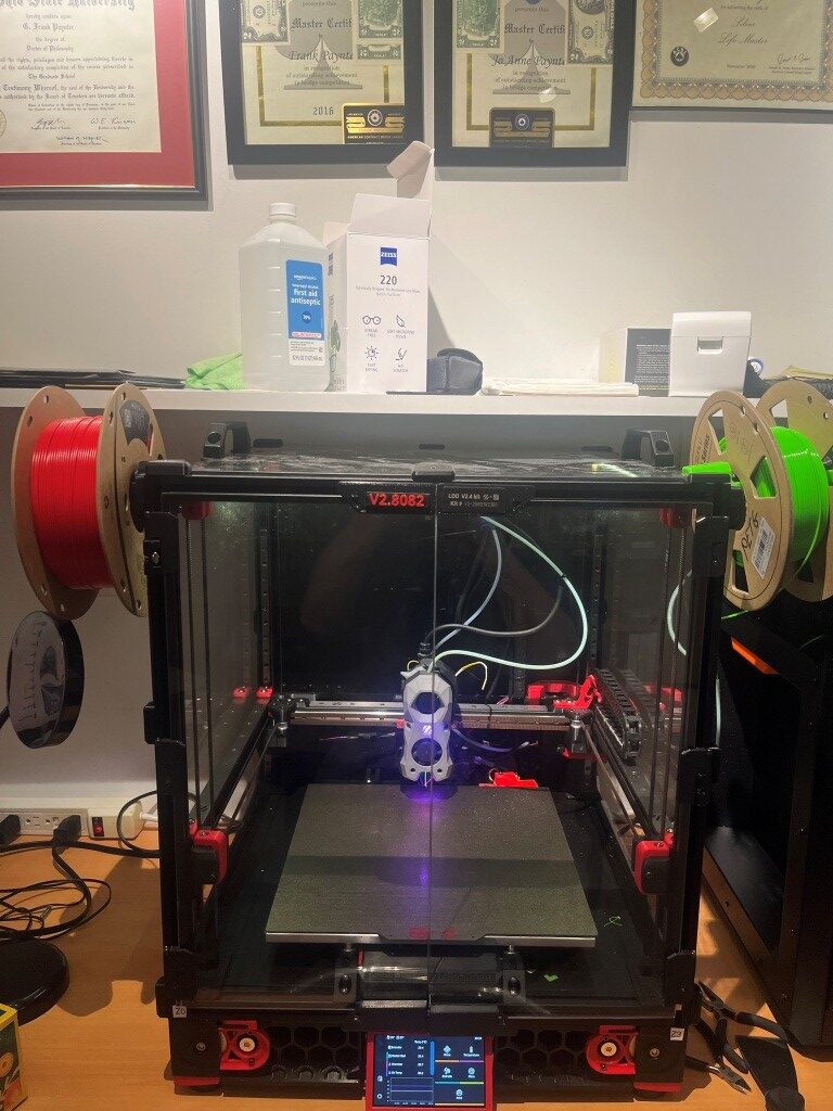
Last May (2025) I started the process of building a Voron 2.4 300x300mm 3D printer, with the ultimate goal of constructing a dual extruder system capable (hopefully) of complex prints requiring soluble supports. Now that I have the printer running with a single ‘Stealthburner’ toolhead, it is time to move on toward my ultimate goal of a dual extruder system.
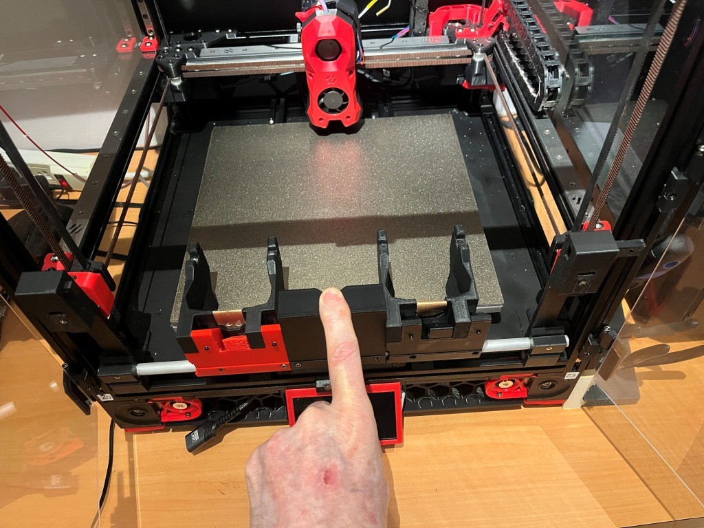
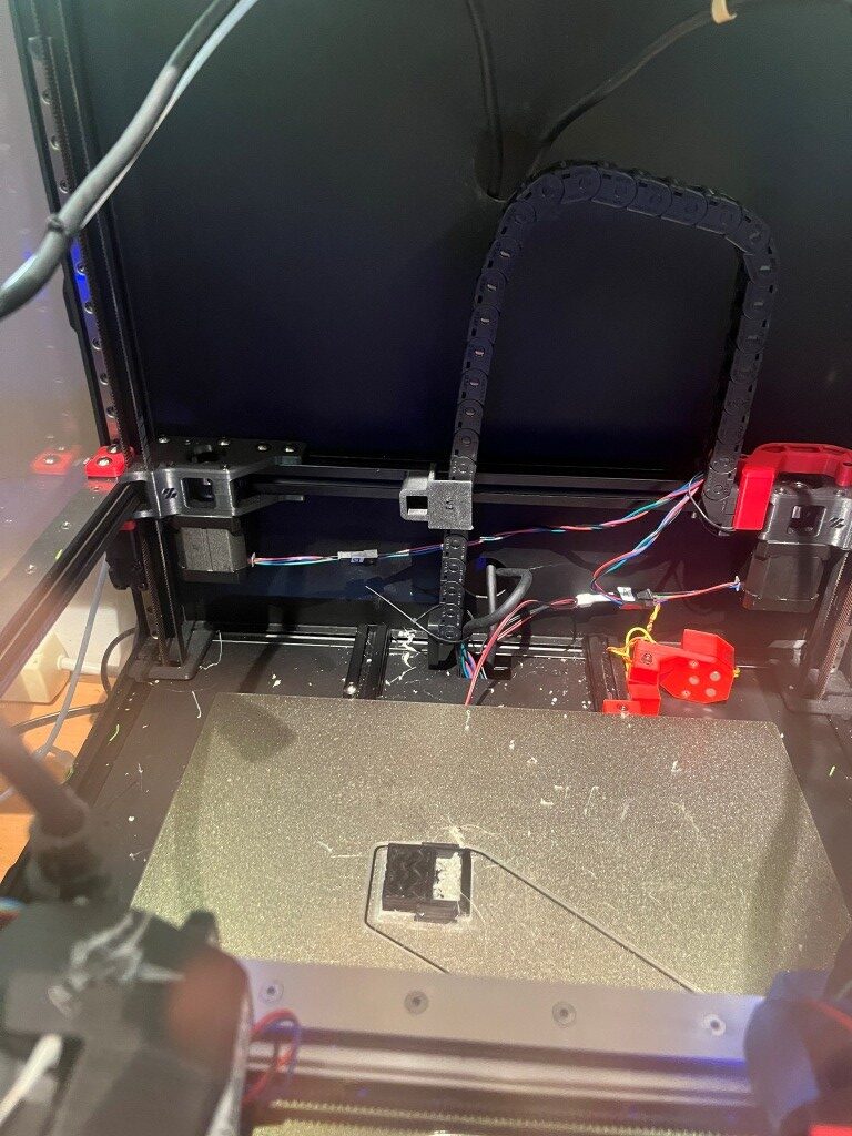
After a LOT of research into the many available toolchanger mods, I chose the MISSChanger (the ‘MISS’ stands for ‘Make It Simple, Stupid!’) mod because unlike all the other mods, this one does not require a ‘top hat’ addition to make room for the top-rail-mounted docking system, room that I do not have in my office. Instead, it uses up about 130 mm of print surface (almost half of my available Y-dimension space on my 300×300 plate at the front of the printer for the docking system. If necessary, however, the docking system can be easily removed to recover the print space, but only at the cost of going back to a single-extruder configuration.
08 November 2025 Update:
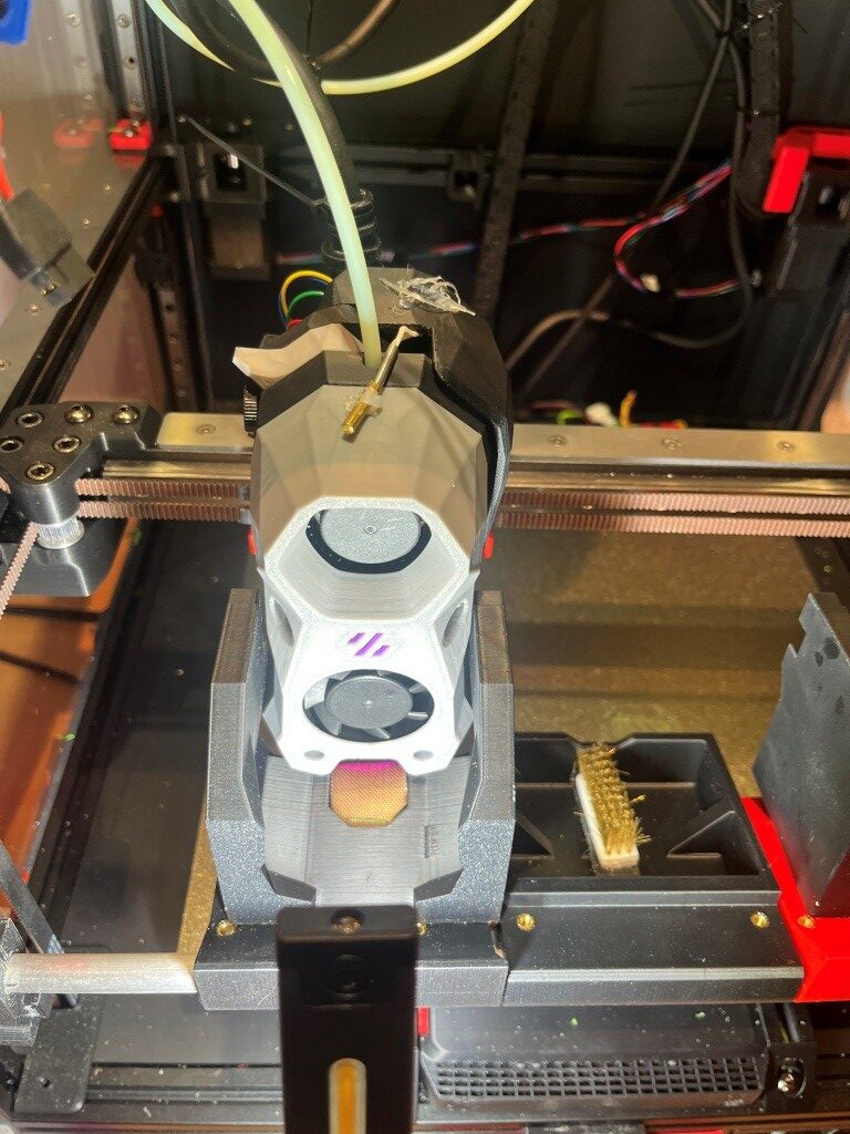
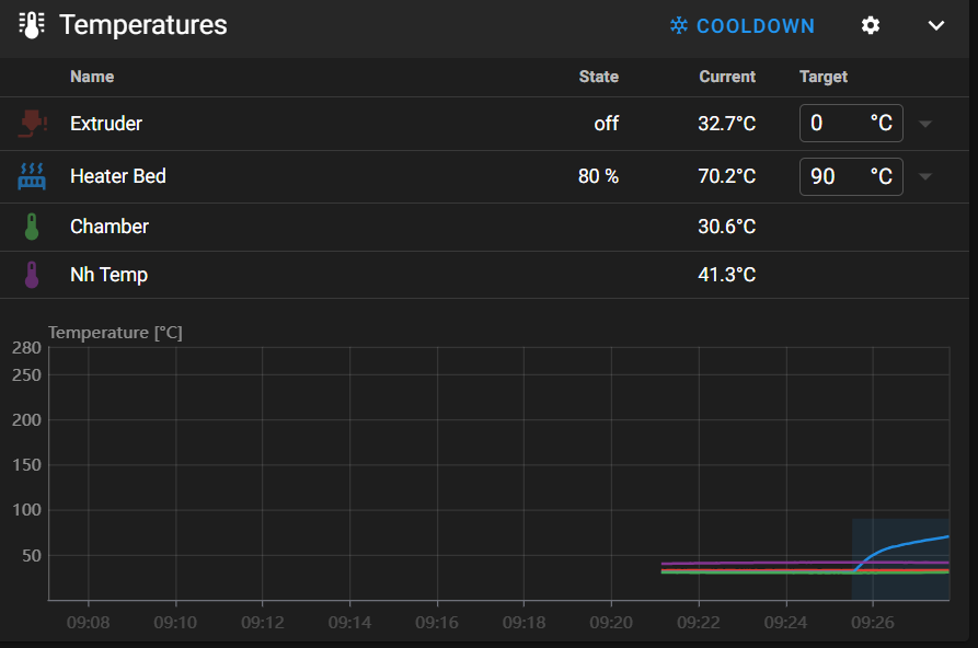
I now have tool changing working, and I was actually able to make a two-color print, as shown in the following short video and a photo of the 10mm two-color calibration cube.
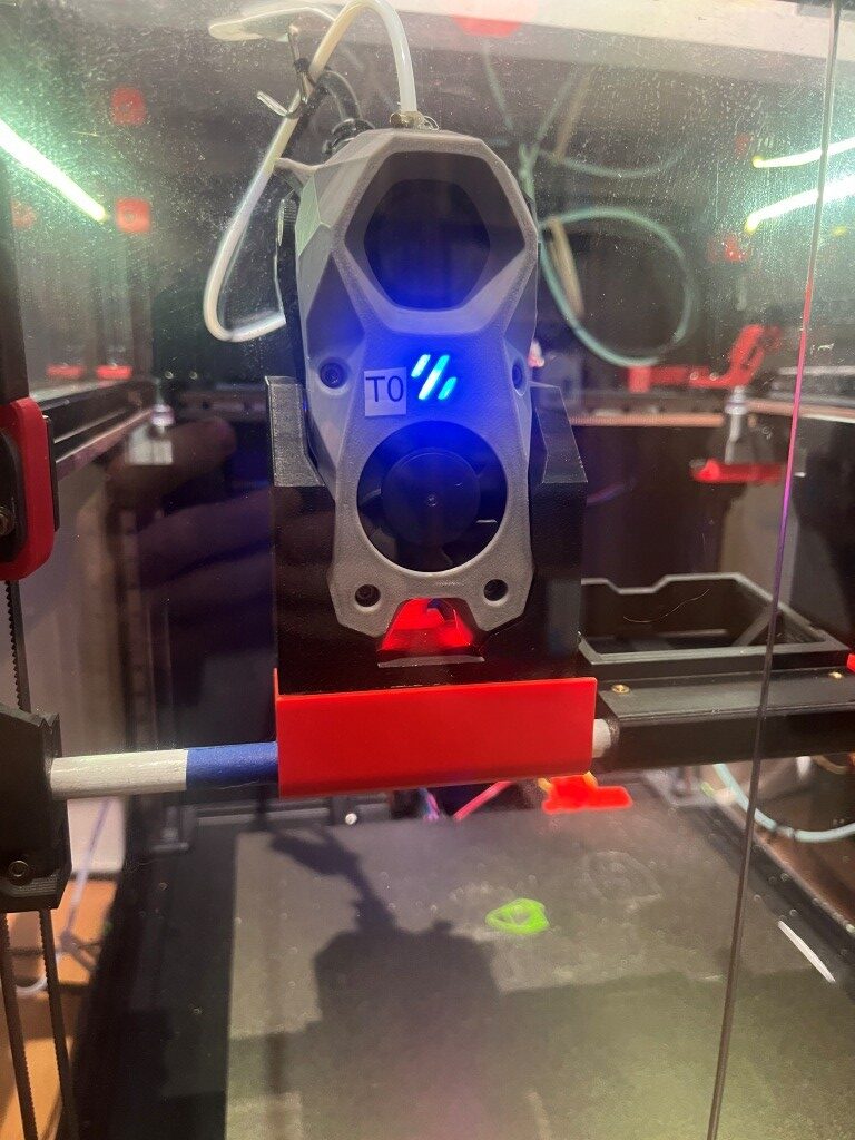
Lots of work still to do. The above print isn’t very high quality, and the zero offset isn’t dialed in yet. In addition I noticed the toolhead logo/nozzle colors were off; the nozzle LEDs were a dark red during print instead of white – which made seeing print details very difficult. Either the STATUS_PRINTING nozzle color isn’t white like I thought, or PRINT_START isn’t changing to STATUS_PRINTING when needed.
I manually checked, and STATUS_PRINTING nozzle LEDs are full white – so that’s not the problem. Looking at PRINT_START I don’t see where the STATUS_xxx macros are used except at the end when STATUS_READY is called.
Side Note: When I started checking where (if anywhere) the stealthburner LED colors were being set at the beginning of a print, I found that they weren’t being set at all, which explains why I wasn’t seeing anything. Also in this process, I discovered that Vin’s MissChanger files contain their own, much more complex PRINT_START macro (among others). This macro is found in ‘misschanger_macros/print_time_default.cfg’, which is included at the very start of Vin’s example ‘printer.cfg’ file. I had blindly copied these include lines into my ‘printer.cfg’ file without ever realizing what was in them, as they didn’t seem to affect much. In particular I never realized there was another PRINT_START macro due to the way that Klipper parses includes – subsequent copies of any section or macro override any previous ones, so my PRINT_START macro always survived the process. I’m not going to worry about this right now – I’ll get to it when I get to it.
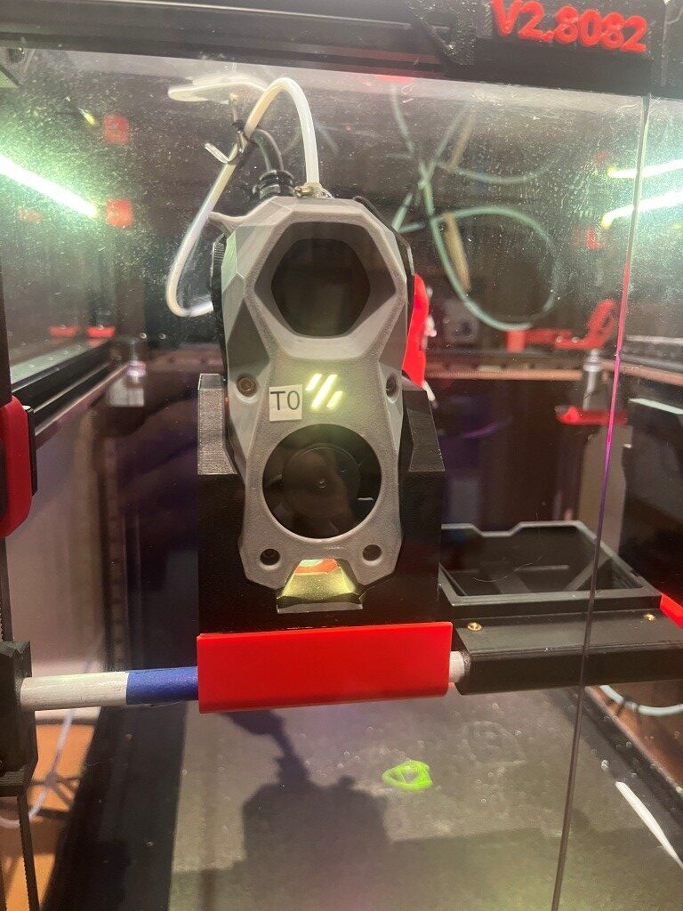
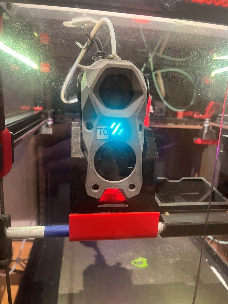
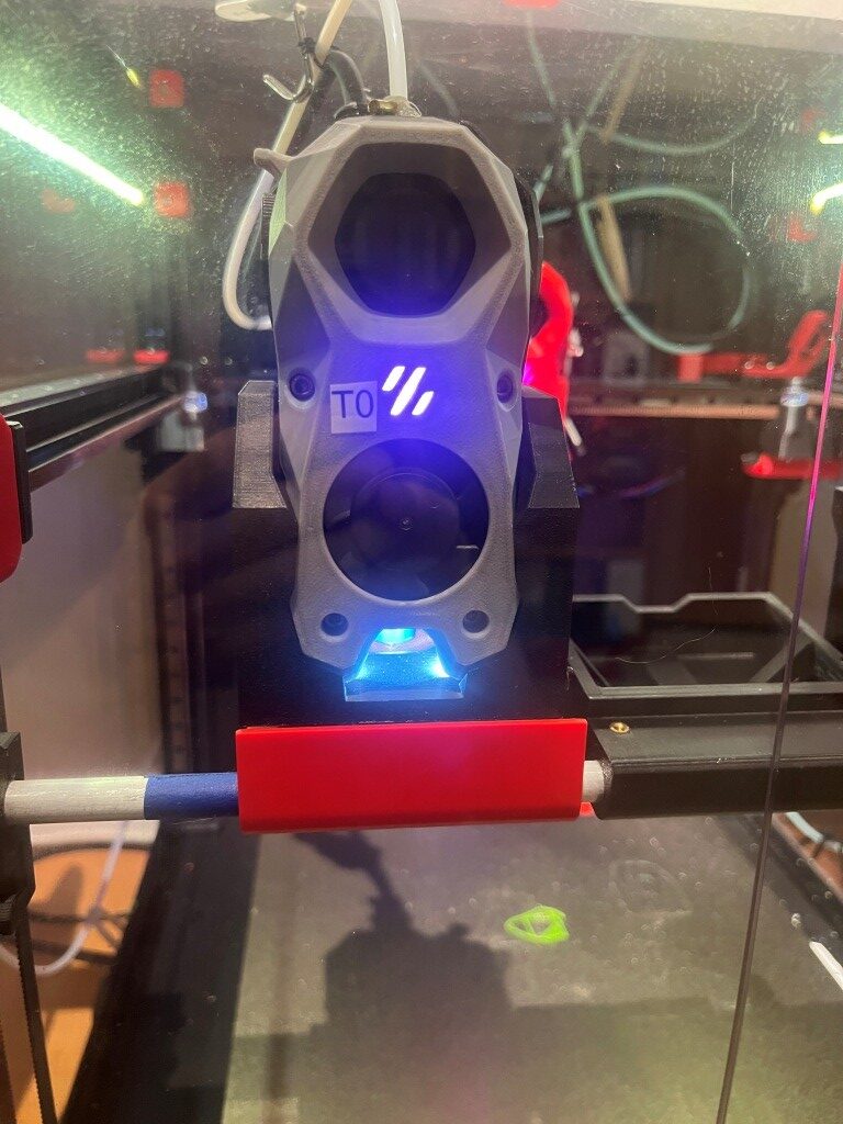
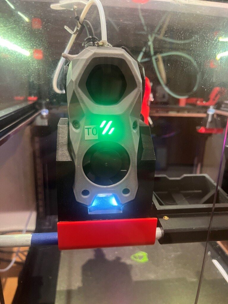
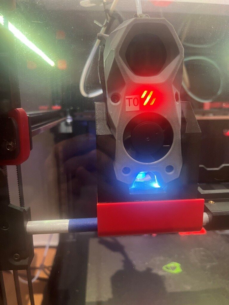
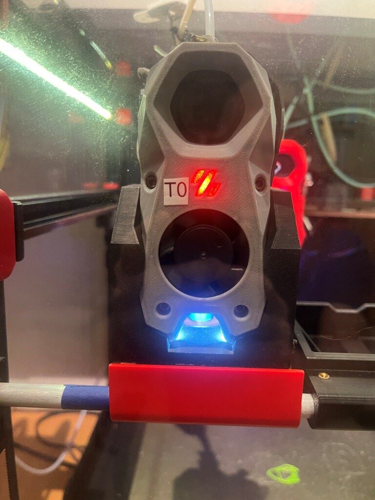
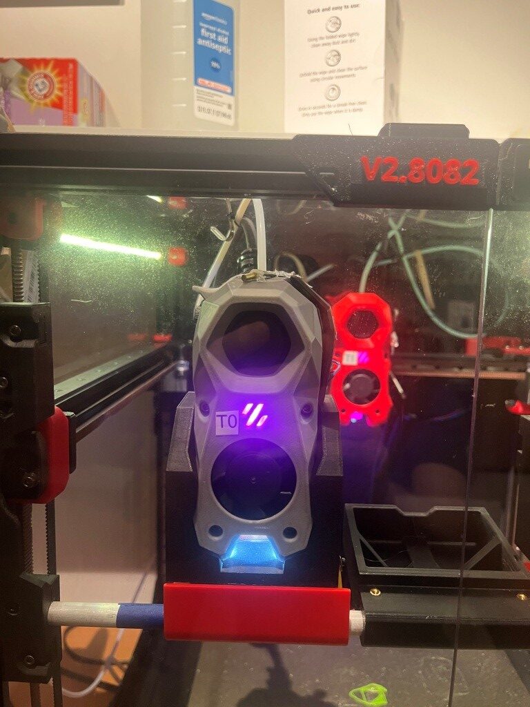
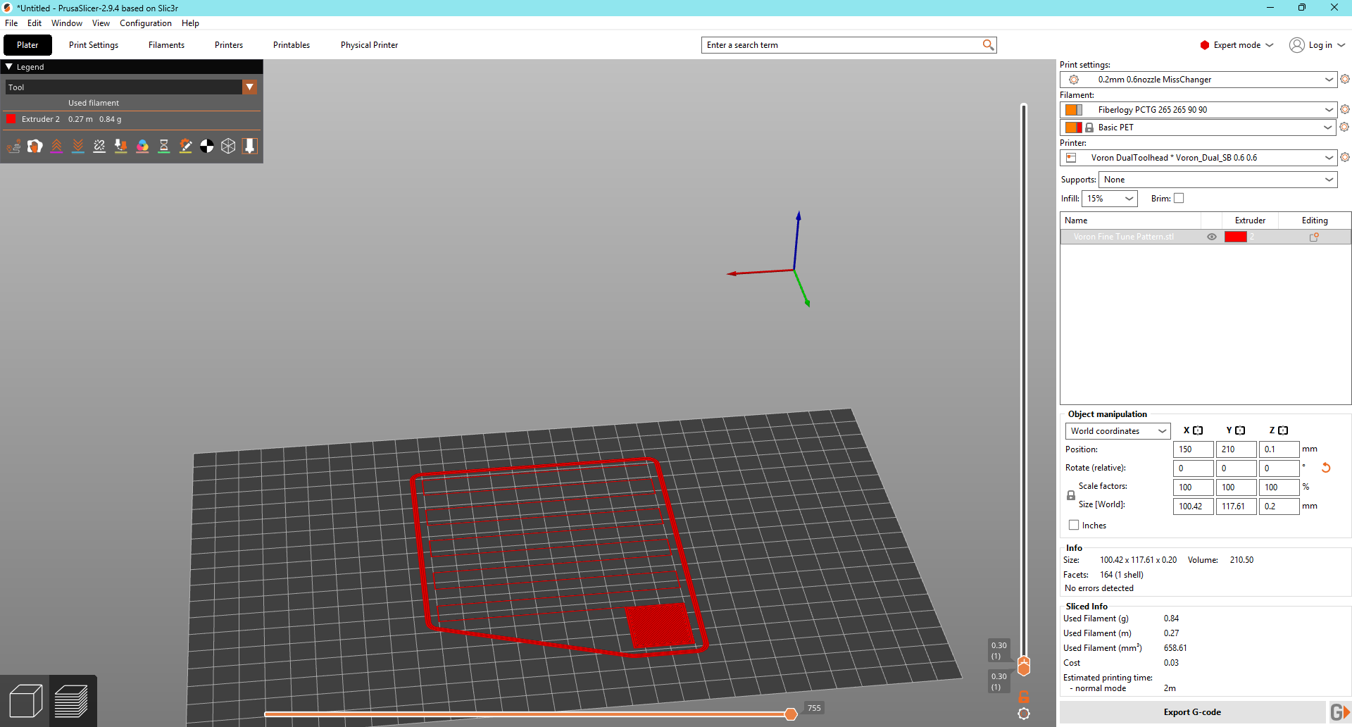
I went into PRINT_START and placed some STATUS_XXX macro calls and some STATUS_MSG debug prints, and will re-do the test print. I also took photos of each defined STATUS_XXX color sets so I can match what I’m seeing with a STATUS_XX call in PRINT_START. See below for the photos:
10 November 2025 Update:
Well, I’m not much smarter than I was yesterday regarding two-color prints, but I think I may have made some progress today. I couldn’t (and still can’t) figure out Vin’s instructions for setting up toolhead Z offsets for tools other than T0. Finally I remembered that Vin’s instructions had me add the following to printer.cfg in the SAVE_CONFIG section:
|
1 2 3 4 5 |
#*# [tool_probe T1] #*# z_offset = -1.750000 #*# #*# [extruder1] #*# |
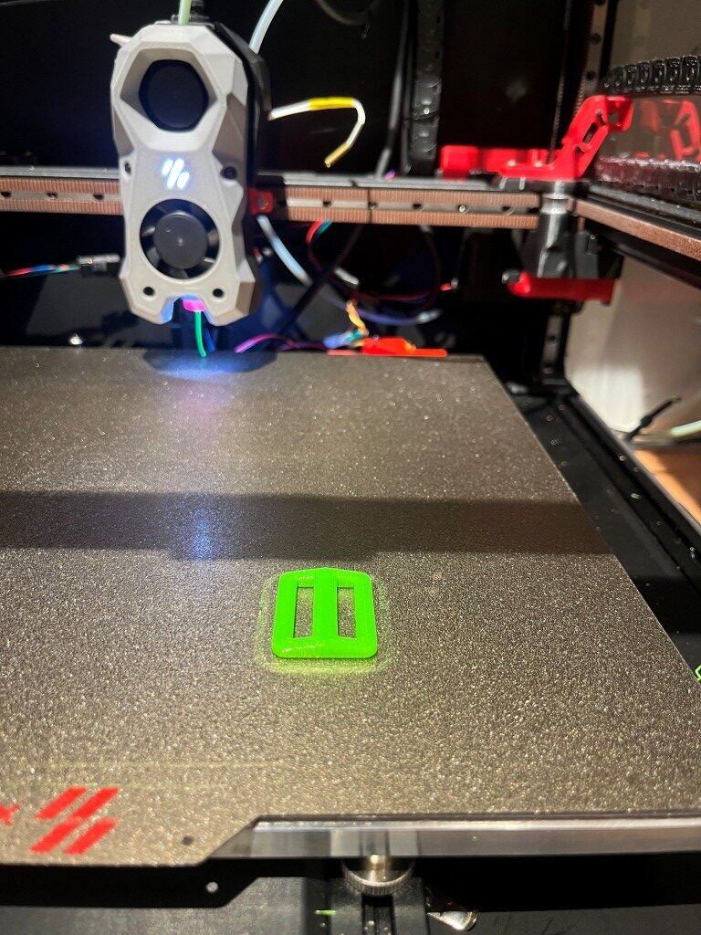
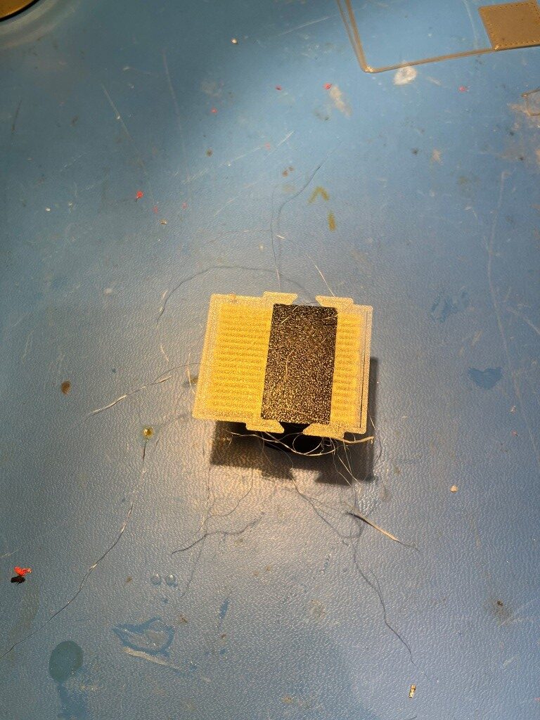
This led me to believe that I could probably just mount T1, tell Klipper to send the toolhead to Z-=0, and use the paper test to set the offset. As far as I can tell, this trick actually worked! So, now I am wondering what all the hooforah is for the Lube_Ball calibration tools and associated config files? Here’s a photo of my two-color calibration block, with no fine tuning done for either toolhead.
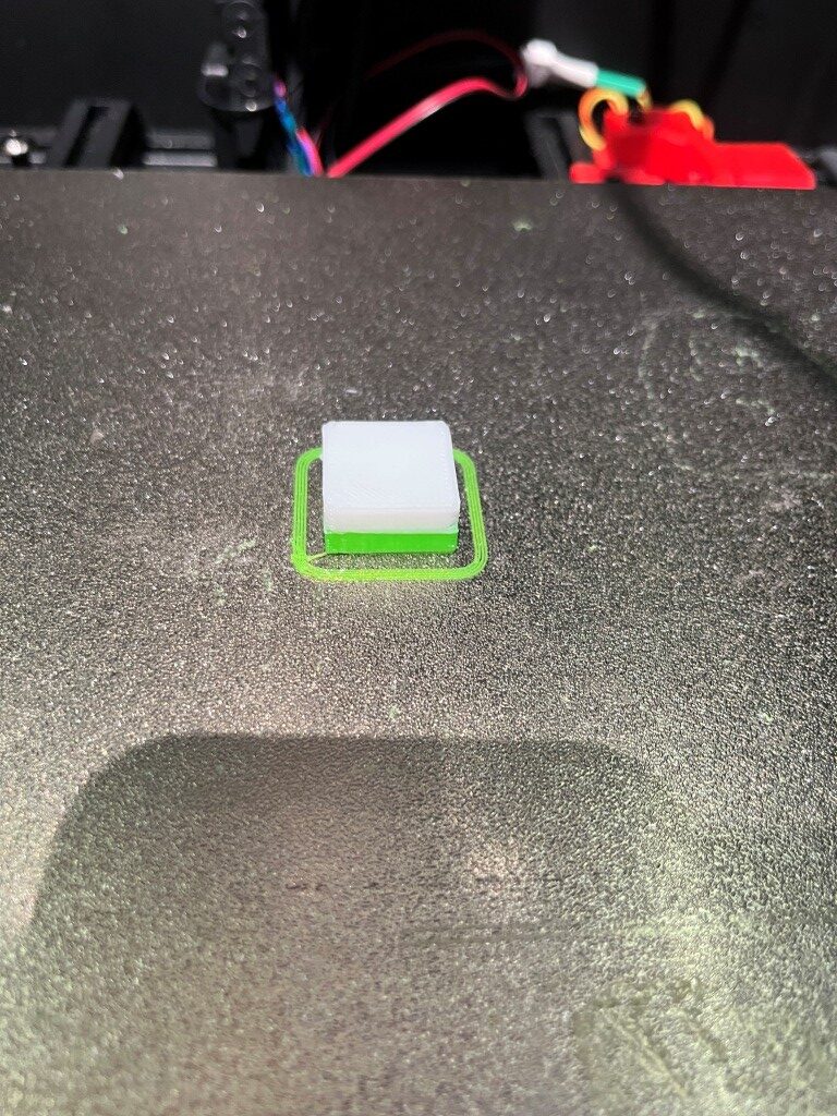
In the above photo, it looks like the T1 z-offset of -1.750 is just a little too much, as the brim lines aren’t squeezed enough to connect to each other. I reduced the offset to -1.700 and ran the print again.
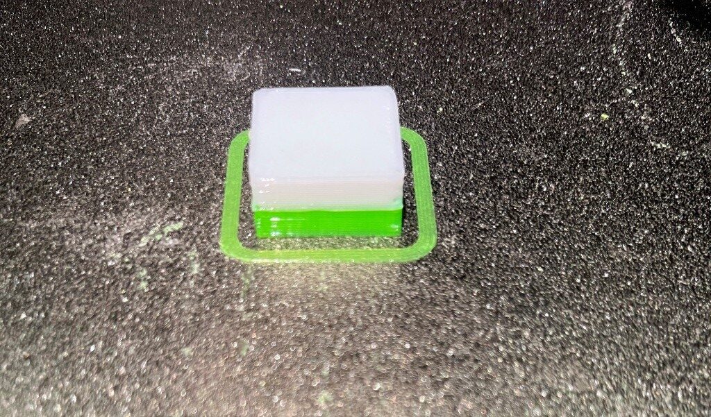
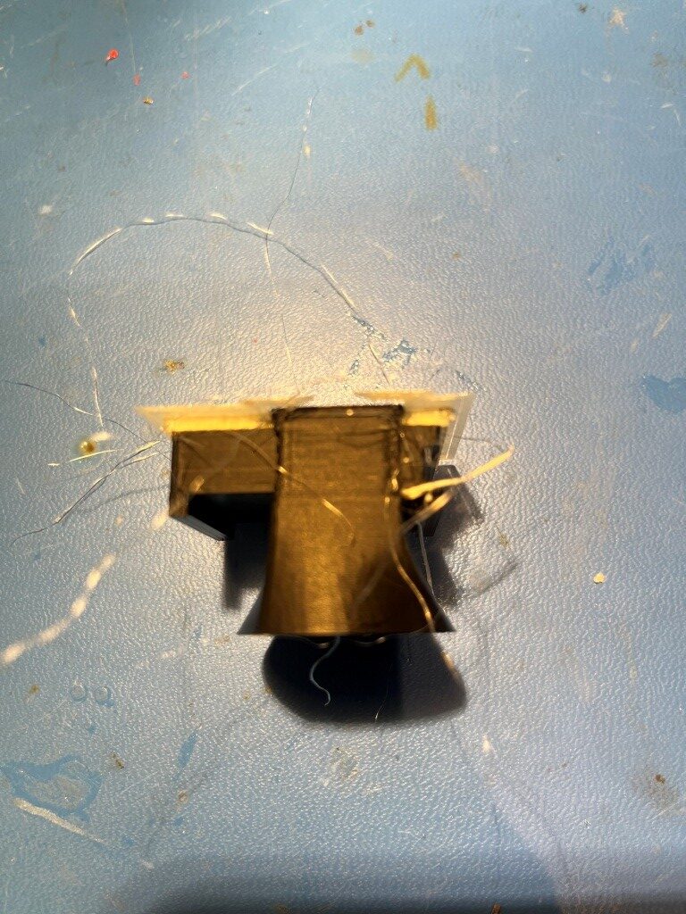
As the above photo shows, this offset produced a much nicer ‘squeeze’ on the brim lines. Now it remains to be seen if this method will hold up over time.
I decided to try Voxel3D_Nederland’s XYZ tuning print, shown here. It will be interesting to see if it confirms the z-offsets I have so far.
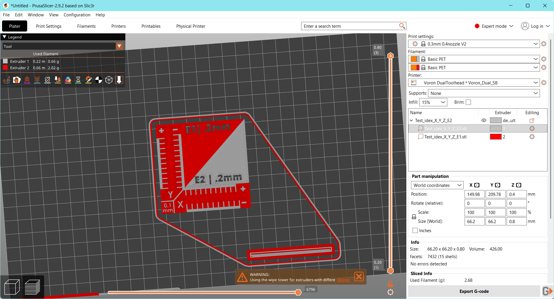
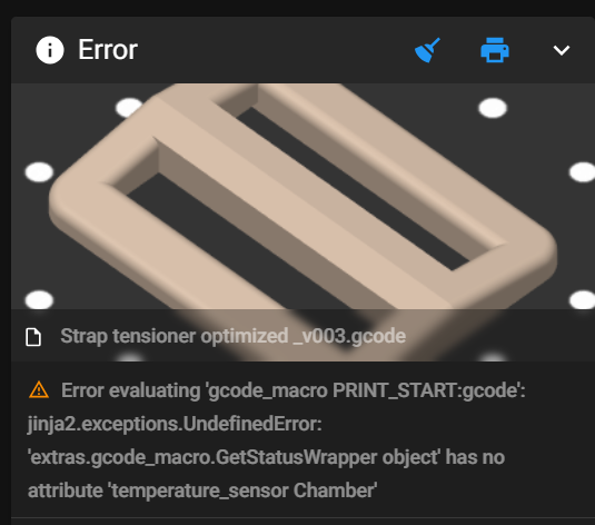
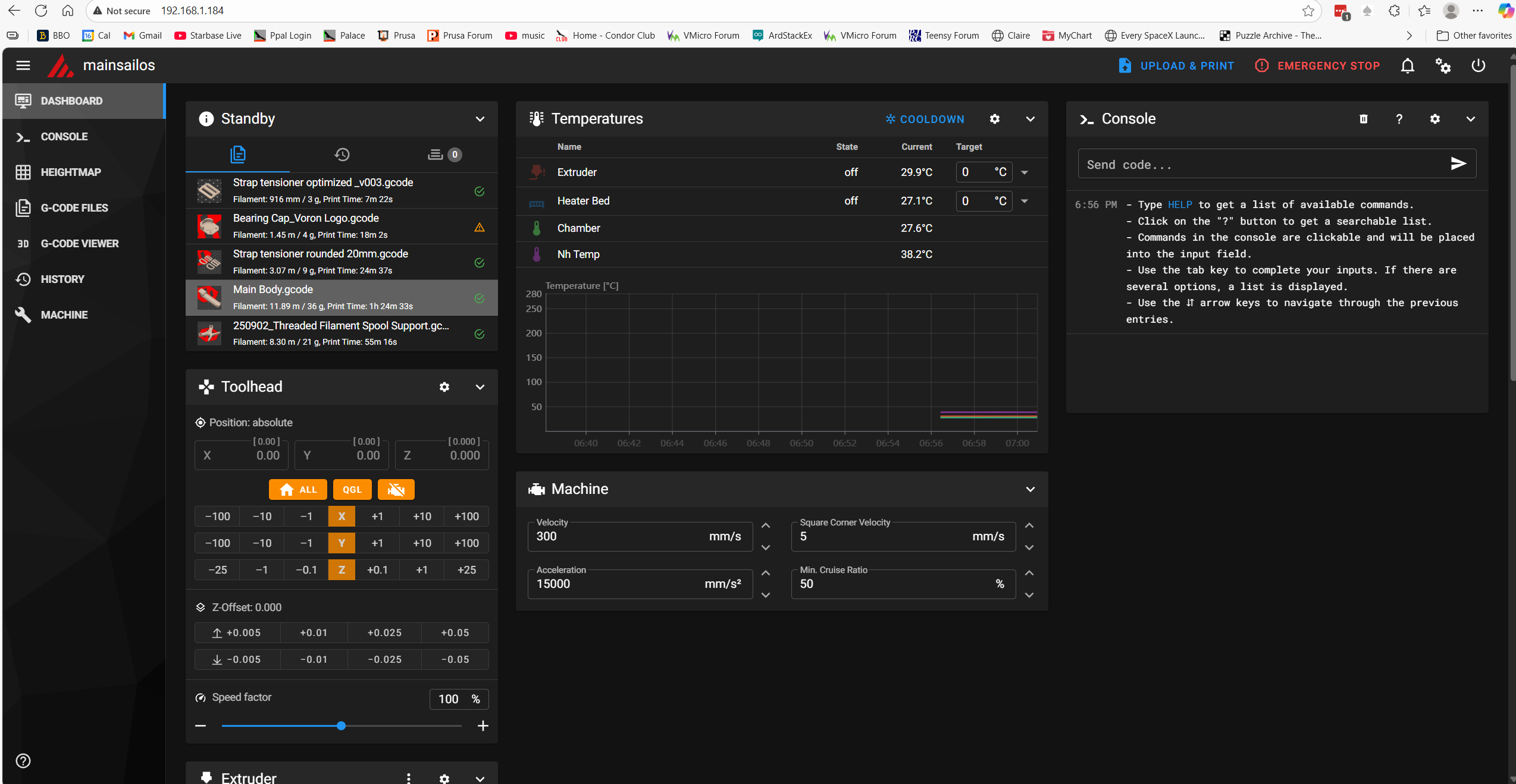
When I tried to print this job, I got an error message that said the extruder was too cool. Then I noticed that the T1 extruder temp was where it should be (240C), but the gcode was trying to print with T0 – oops. I hope this is actually a problem with the slicer, as my test prints with the two-color 10mm cal cube have worked correctly.
11 November 2025 Update:
I ran into yet another odd problem with the offsets. After getting the T1 z-offset nailed down I tried another print, and this on failed miserably, with the extruder starting out way too high. I ‘fine-tuned’ it back down again, but it took almost all (and then some) of the original -1.700mm offset back out again – which can’t be right. I re-ran PROBE_CALIBRATE on T1 and got close to the original -1.700mm, and when I tried the print again, it worked fine. However, when I tried to print the same job a second time without any changes, the same thing (extruder tip way too high) happened again. After thinking about this for a while, I began to think that the culprit was the ‘trigger_to_bottom = -1.896’ entry in the ‘[tools_calibrate]’ section of misschanger_settings.cfg. Maybe somehow this was being added to the T1 z-offset?
So, I set the ‘trigger_to_bottom’ value to zero and tried again, and saw that the 10mm two-color print was now consistently perfect. I am now in the process of making several prints in a row to verify that the z-offset is now consistently correct.
Not quite. I got a couple of prints where the extruder started out about 0.05mm too low. Not quite sure that’s all that bad, so I’m going to keep the offset at -1.700 for a few more prints.
I added 0.05mm to the z-offset to arrive at -1.750mm and restarted the firmware, and this time the extruder tip was too high by about 0.900mm – I have no idea why. The ‘trigger_to_bottom_z’ value in misschanger_settings.cfg is still zero. I restarted again and tried another print. This time the extruder tip was too high by about 0.6mm (could be the same as the 0.9 from before). Tried another print without accepting the 0.6 offset recommendation and without restarting. Same thing – extruder tip too high
Chose ‘apply offset’ Klipper restarted, and z_offset in [tool_probe T1 changed from -1.75 to -1.10mm. Did another print. Job went OK. Trying another print without changing anything. Good print.
Did a full Klipper reboot, selected test job without any other changes. This time the extruder tip was WAY too high; almost -2.0mm. At this point the printer.cfg tool_probe T1 offset is -1.10, so to get the extruder down another 1.9mm would put the extruder into positive territory – wow!.
Did a Home-All, then sent extruder to z=0; Had to RAISE the extruder by 0.60mm in order to get the proper ‘paper’ thickness. Did another PROBE_CALIBRATE; the result was _0.477. Accepted the result, and the T1 offset changed from -1.100 to … -1.100 – NO CHANGE! Did a save & restart from MainSail, and checked printer.cfg again. T1 offset is still -1.100 – unchanged. Did a HOME ALL, then checked extruder zero; had to raise the tip 0.5mm for a good ‘paper drag’.
Did another print without changing anything (T1 z_offset still at -1.1). Had to ‘fine-tune’ up 0.5mm, so this time I accepted the change. This time the T1 z_offset did not change with the restart – had to manually revise it – to -1.6000.
Did a ‘save & restart, HOME ALL, and sent extruder to z=0. This time I had to LOWER the extruder tip by 0.5mm for good paper drag. So I adjusted T1 z_offset by 0.5mm UP (minus), but this caused me to have to LOWER it by 0.5 after a HOME ALL.
Alright – there is certainly something rotten in Denmark. I changed to T0, sent the extruder to 150,200,0 and the paper check was fine – within 0.1mm. I did this because of this sentence in Vin’s instructions; “test the z-offset with the paper test. – If it is good then you set up the trigger_to_bottom_z value correctly. However, I had long since manually set the ‘trigger_to_bottom_z’ value to 0, so I really don’t undersdand how this works.
Next, I switched from T0 to T1, ran HOME ALL & QGL. Then tested offset by driving extruder to zero. This time it was pretty much spot-on – within 0.1mm. Tried another test print; good print.
Do ten test prints:
- Print 1: OK.
- Print 2: OK; a skosh low (brim was hard to scrape off, but not impossible)
- Print 3: OK;
- Print 4: Failed – extruder started out too high
- Print 5: Failed – extruder started out too high
- Print 6: Failed – extruder started out too high
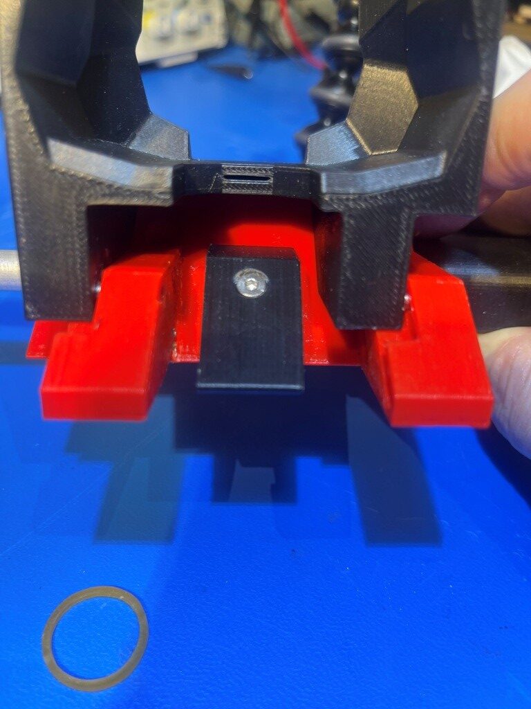
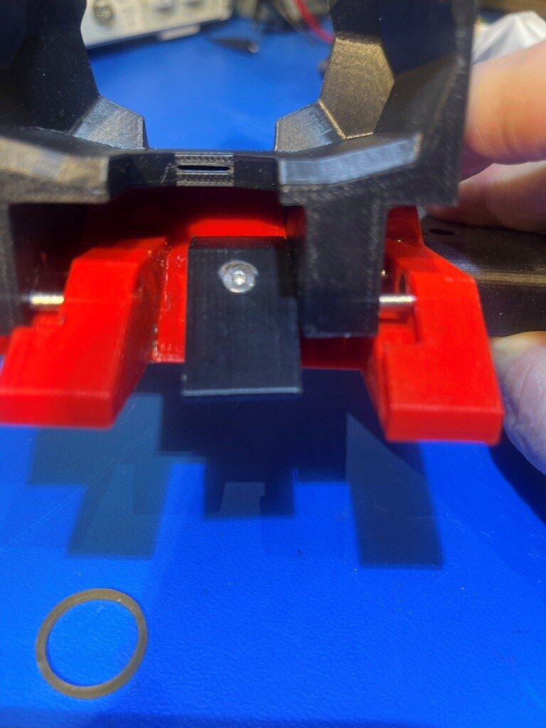
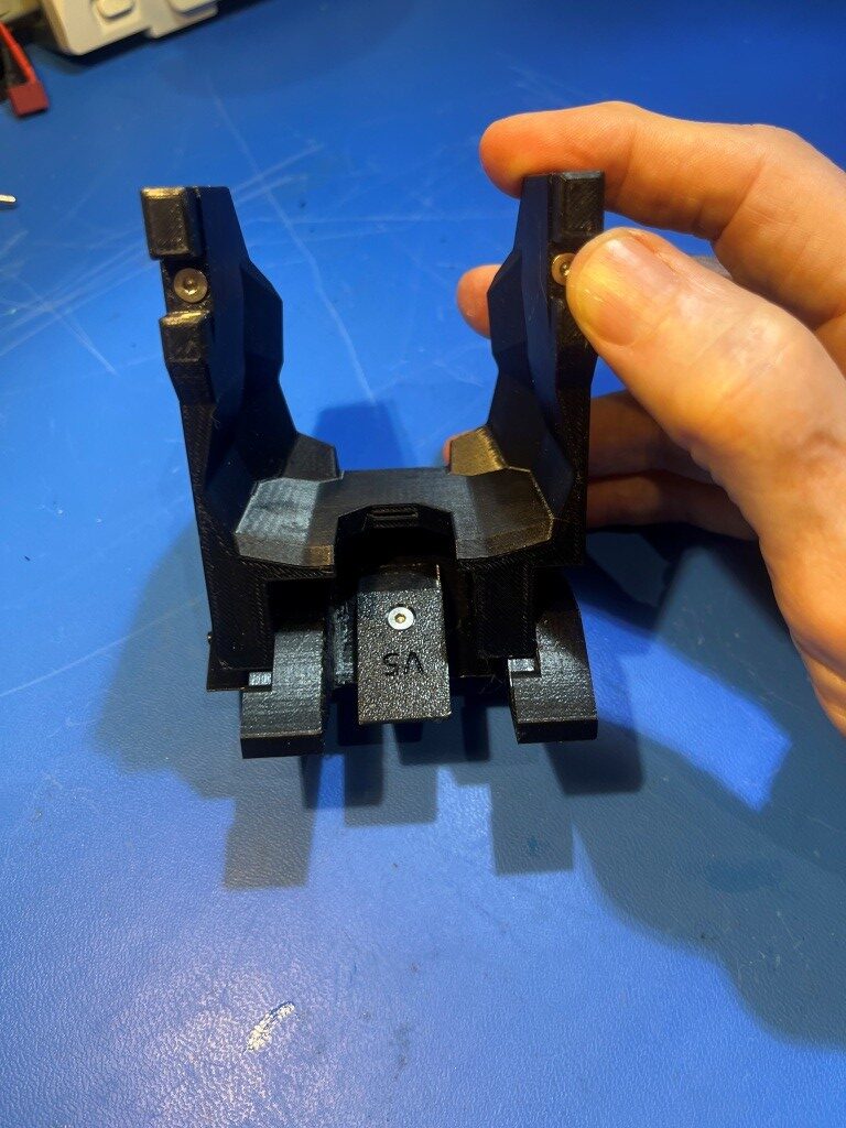
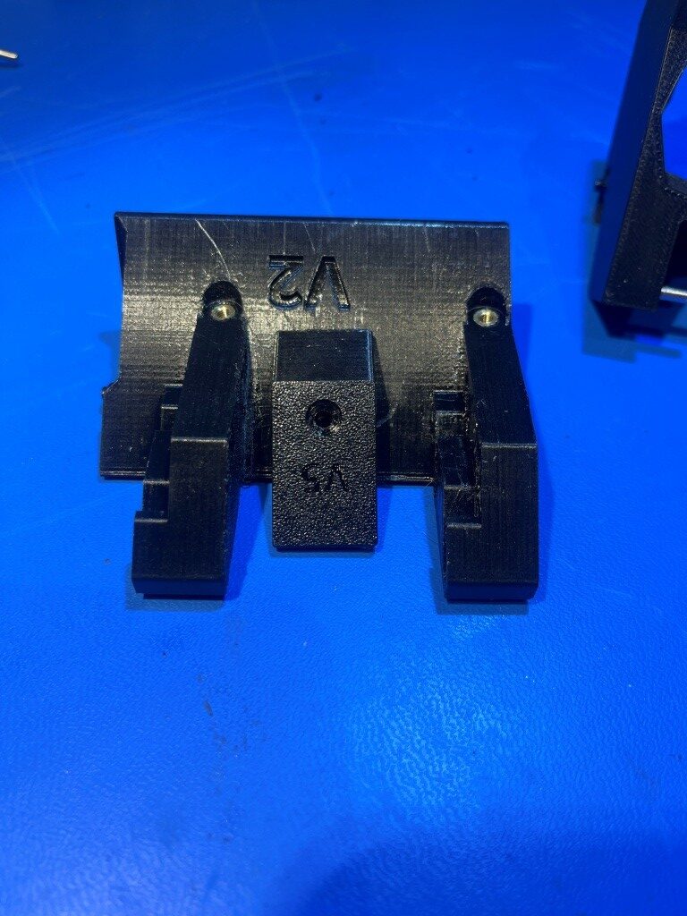
I inspected the T1 mount on the carrier, and it seemed pretty tight. Also the screw-in extruder tip seemed secure, so those are probably not the culprit. At this point I noticed that starting when starting a print job, the printer skipped both the HOME ALL & QGL steps (not in PRINT_START?). Maybe that is what is causing the wandering z_offset?
- Print 1: After HOME ALL & QGL. looks good – almost perfect first layer.
- Print 2: After HOME ALL & QGL. looks good – almost perfect first layer.
- Print 3: After HOME ALL & QGL. Good print, but extruder a little high.
- Print 4: After HOME ALL & QGL. Poor print. Extruder started out too high
- Print 5 After HA & QGL. Poor print. Extruder started out too high
- Print 6 After HA & QGL. Poor print. Extruder started out too high
- Print 7 After HA & QGL. Excellent print – almost perfect first layer
At this point, it looks like I can consistently get two-color prints that have a functional (if not pretty) first layer with T1, without requiring any ‘fine-tune’ adjustments (although smaller ‘fine tune’ adjustments might be advisable). And this is with the ‘trigger_to_bottom_z’ parameter in the ‘tools_calibrate’ section of misschanger_settings.cfg set to zero.
12 November 2025 Update:
At this point, I think I can successfully do two-color/material prints, with maybe the need for some minor ‘fine-tuning’. However, it is clear that the PRINT_START macro needs to make certain that the HOME_ALL and QGL operations are performed before each print actually starts. Looking at the PRINT_START macro, I see:
|
1 2 3 4 5 6 7 8 9 10 11 12 13 14 15 16 17 18 19 20 21 22 23 24 25 26 27 28 29 30 31 32 33 34 35 36 37 |
[gcode_macro PRINT_START] description: Multi-tool start (heat active extruder + bed/chamber) gcode: STATUS_MSG MSG="PRINT_START: T{TOOL} Bed={BED} Temp={TOOL_TEMP} Size={params.FIRST_LAYER_PRINT_SIZE|default(0.2)}" TYPE=echo {% set TOOL = params.TOOL|default(0)|int %} {% set EXTRUDER = 'extruder' + (TOOL|string if TOOL > 0 else '') %} # 'extruder' or 'extruder1' {% set BED = params.BED_TEMP|default(60)|int %} {% set TOOL_TEMP = params.TOOL_TEMP|default(200)|int %} {% set T1_TEMP = params.T1_TEMP|default(TOOL_TEMP)|int %} # Use T1_TEMP if passed # Force home/level if uninitialized {% if printer.toolhead.homed_axes != 'xyz' %} STATUS_MSG MSG="Printer uninitialized - Homing + Leveling..." TYPE=echo G28 # Home all QUAD_GANTRY_LEVEL # Level {% endif %} SELECT_TOOL T={TOOL} # Switch to T1 if TOOL=1 #STATUS_MSG MSG="PRINT_START: T{TOOL} Bed={BED} Temp={TOOL_TEMP} Size={params.FIRST_LAYER_PRINT_SIZE|default(0.2)}" TYPE=echo STATUS_MSG MSG="STATUS_MESHING" STATUS_MESHING #Toolhead LEDs BED_MESH_CLEAR BED_MESH_CALIBRATE # Mesh after level # Heat Bed STATUS_HEATING #Toolhead LEDs SET_HEATER_TEMPERATURE HEATER=heater_bed TARGET={BED} TEMPERATURE_WAIT SENSOR=heater_bed MINIMUM={BED-2} MAXIMUM={BED+2} # Heat Active Extruder SET_HEATER_TEMPERATURE HEATER={EXTRUDER} TARGET={TOOL_TEMP} TEMPERATURE_WAIT SENSOR={EXTRUDER} MINIMUM={TOOL_TEMP-2} MAXIMUM={TOOL_TEMP+2} G90 # Absolute STATUS_PRINTING # LEDs ready! |
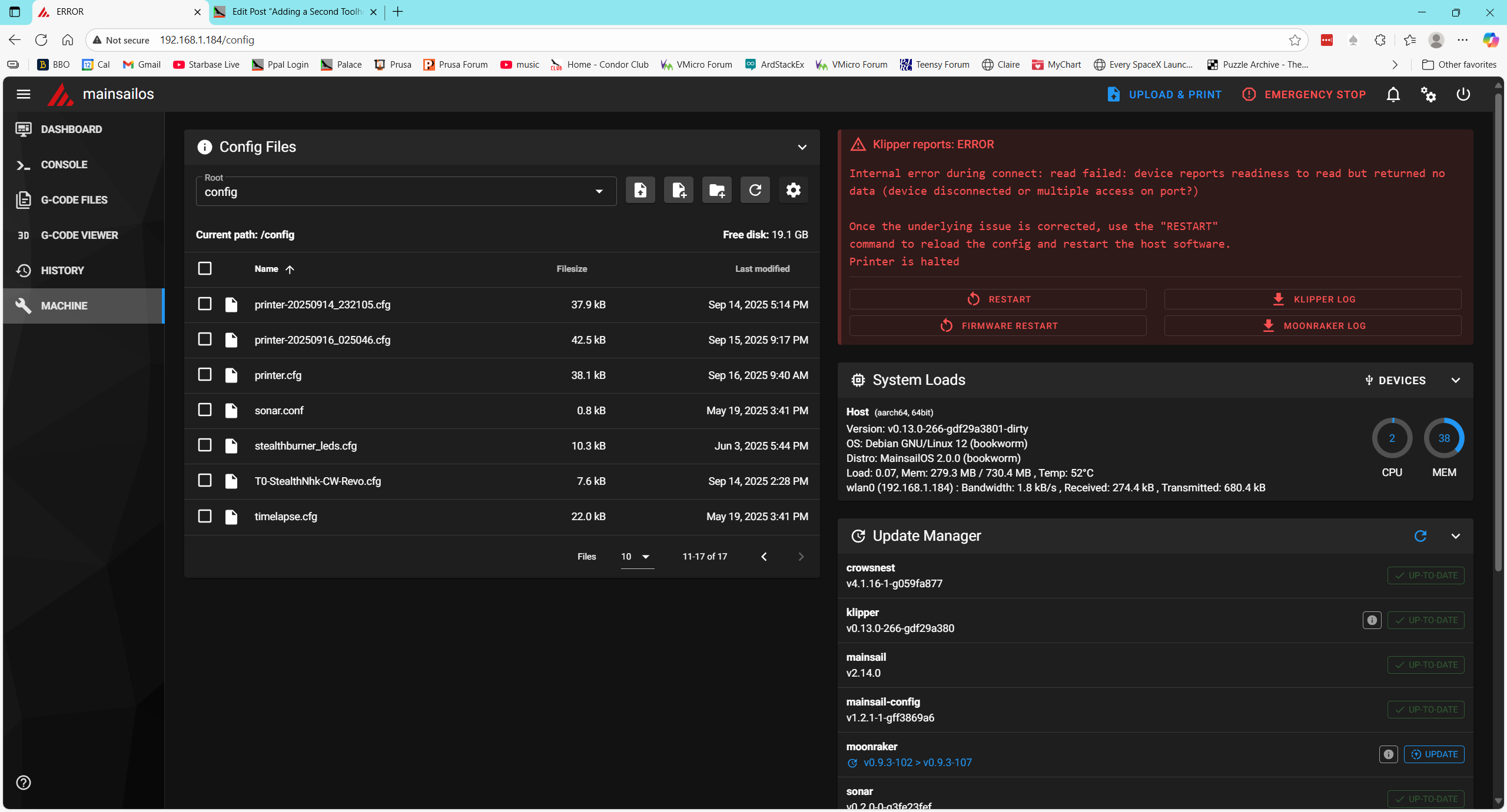
So, at least in theory the PRINT_START macro does the HOME_ALL (G28) and QGL if it hasn’t already been done. However, I’m not certain it *ever* does this. I looked to see if there were any status messages emitted, but couldn’t find anything. In fact, there don’t appear to be *any* status messages in the Klippy log. I asked Grok about this, and apparently the only way to get user outputs to the Klippy.log is to put in RESPOND lines. So I put a RESPOND MSG=”In PRINT_START” in the PRINT_START macro. Also, I commented out the ‘if’ statement guarding the HOME_ALL (G28) and QGL commands in PRINT_START to see if that would actually happen, and started a new test print. Console output confirmed that the G28 & QGL commands were actually performed, so we’ll see. Yep, the print started OK (with the extruder tip maybe just a bit too far from the bed, but still very nice!).
The RESPOND message did not appear in Klippy.log – bummer.
I think I’m going to declare victory at this point, and start working on the status LED problem. The problem is that the STATUS_XX commands seem to be going to T0 instead of T1. From the console log I see:
|
1 2 3 4 5 6 7 8 9 10 11 12 13 14 15 16 17 18 19 20 21 22 23 24 25 26 27 28 29 30 31 32 33 34 35 36 37 38 39 40 41 42 43 44 45 46 47 48 49 50 51 52 53 54 55 56 57 58 59 60 61 62 63 64 65 66 67 68 69 70 71 72 73 74 75 |
Voron24_30 Send code... 12:58 PM Done printing file 12:55 PM Klipper state: Ready 12:55 PM // T0: _set_sb_leds_by_name. led = t0_sb_leds 12:55 PM Klipper state: Ready 12:55 PM // T0: _set_sb_leds_by_name. led = t0_sb_leds 12:55 PM Klipper state: Ready 12:55 PM // T0: Status Ready. led = t0_sb_leds 12:55 PM Selected tool 0 (tool T0) 12:55 PM Found active tool probe: tool_probe T0 12:55 PM Activating extruder extruder 12:55 PM All probes triggered 12:55 PM Toolhead T0 Select Macro 12:52 PM Klipper state: Ready 12:52 PM // T1: _set_sb_leds_by_name. led = t1_sb_leds 12:52 PM Klipper state: Ready 12:52 PM // T1: _set_sb_leds_by_name. led = t1_sb_leds 12:52 PM Klipper state: Ready 12:52 PM // T1: Status Ready. led = t1_sb_leds 12:52 PM Tool tool T1 already selected 12:52 PM Klipper state: Ready 12:52 PM // T1: _set_sb_leds_by_name. led = t0_sb_leds 12:52 PM Klipper state: Ready 12:52 PM // T1: _set_sb_leds_by_name. led = t0_sb_leds 12:50 PM Klipper state: Ready 12:50 PM // T1: _set_sb_leds_by_name. led = t0_sb_leds 12:50 PM Klipper state: Ready 12:50 PM // T1: _set_sb_leds_by_name. led = t0_sb_leds 12:50 PM ... 12:48 PM TOOL_BED_MESH_CALIBRATE... 12:48 PM Klipper state: Ready 12:48 PM // T1: _set_sb_leds_by_name. led = t0_sb_leds 12:48 PM Klipper state: Ready 12:48 PM // T1: _set_sb_leds_by_name. led = t0_sb_leds 12:48 PM Klipper state: Ready 12:48 PM // T1: STATUS_MESHING 12:48 PM Tool tool T1 already selected |
From the above output, I can see that the ‘STATUS_MESHING’ command was executed at 12:48, but the subsequent call to _set_sb_leds_by_name was called with ‘led = t0_sb_leds’ instead of ‘t1_sb_leds’, but I didn’t see any actual status change messages other than the one ‘STATUS_MESHING’ output. I think I need to edit ALL the STATUS_XX messages to include a STATUS_MSG MSG=”[current status call]” so I can track progress.
Saved all relevant config files (and printer.cfg backups) to ‘config-20251112-131701.zip’, and then deleted all the backup files.
Opened 251103_shared_stealthburner_leds.cfg and edited all ‘gcode_macro status_xxx’ macros to include a STATUS_MSG MSG = “status_xxx” line. Then I restarted Klipper, cleared the console and started another test print.
I noted that the printer started out with T0 initialized and it did the initial HOME_ALL & QGL with T0. Then changed tools and did STATUS_MESHING (with led = t0_sb_leds). Then a full mesh calibration, then // T1: status_heating (led = t0_sb_leds). I noted that the T0 leds did, in fact, change to the ‘STATUS_HEATING’ color set.
I got some Grok help in debugging this situation, and now the LED action seems to be following the correct toolhead. The affected files were 251103_shared_stealthburner_leds.cfg and 251103_paynter_toolchanger.cfg.
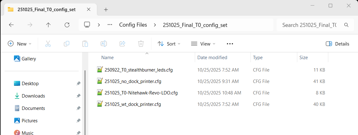
I saved the entire configuration set in ‘config-20251112-143625.zip’ in the MissChanger/Config Files folder.
Not so fast! There were a few more bugs to work out, but with Grok’s help we seem to have exterminated them – at least so far. I again saved the configuration set in MissChanger/Config Files/config-20251112-173325.zip
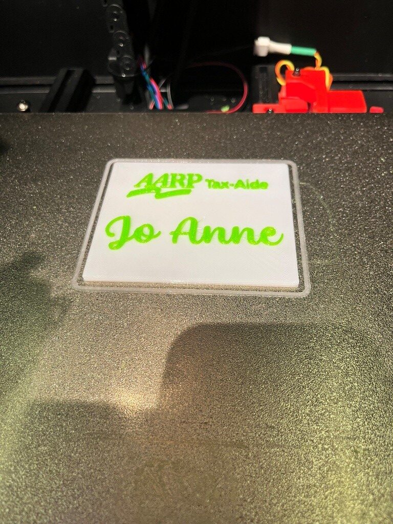
At this point I can print a two-color model reasonably consistently, with toolhead LED colors changing through ‘status_cal_z’, ‘status_meshing’, ‘status_heating’, then ‘status_printing’ and finally to ‘status_ready’ after the print concludes – yay! Here is a photo of a two-color print I just did from a design I created some time ago with my old Flashforge Pro IDEX printer (before I threw it in the trash!)
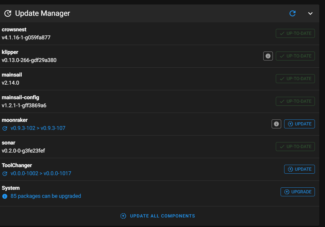
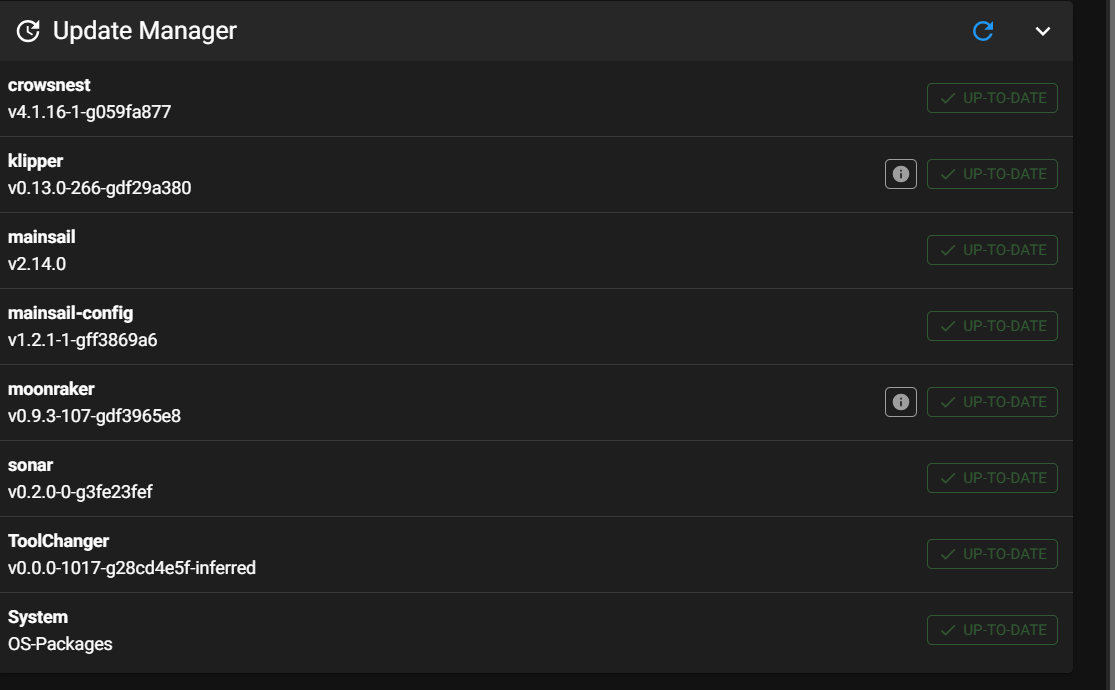
30 November 2025 Update:
Well, it has certainly been an interesting adventure so far, but I think I may have actually gotten to the point where I can do dual-material prints with my Voron printer. The last set of hurdles to surmount were a series of infinite hangs during tool changes, caused by poorly formed macros that were way too picky about extruder temperatures. The macros wanted to wait until the extruder temperature was just right, and sometimes the extruder in question just didn’t want to be that exact. This caused long waits (on the order of 30 seconds) before picking up the next tool, and eventually the printer wouldn’t pick up the next tool at all. I got a lot of help from Grok running this down, and I am now a real fan of this AI. Its superpower is a combination of an in-depth understanding of Klipper (by reading the manual at about 10000x human speed, with perfect recall) combined with the ability to grind through huge mind-numbing klippy.log files and then use that information to pinpoint the place(s) in my macros where things weren’t working correctly. For instance, here is one of several macros that regulate the process of changing from one toolhead to another:
|
1 2 3 4 5 6 7 8 9 10 11 12 13 14 15 16 17 18 19 20 21 22 23 24 25 26 27 28 29 30 31 32 33 34 35 36 37 |
#-------------------------------------------------------------------- [gcode_macro _TOOL_DROPOFF] gcode: ## Variables {% set tn = params.TN|string %} {% set tool = printer['tool ' + tn] %} {% set x = tool.params_park_x|float %} {% set y = tool.params_park_y|float %} {% set z = tool.params_park_z|float %} {% set safe_y = tool.params_safe_y|float %} {% set fast = tool.params_fast_speed|float %} {% set path = tool['params_' ~ tool.params_type ~ '_path'] %} {% set max_z = printer.configfile.config["stepper_z"]["position_max"]|float %} {% set min_z = tool.params_min_z|float %} {% set z_hop = tool.params_z_hop|default(1.0)|float %} {% set cur_y = printer.toolhead.position[1]|float %} {% set cur_z = printer.toolhead.position[2]|float %} G90 ## Safety move {% if cur_y < safe_y %} _CLIENT_LINEAR_MOVE Y={safe_y} F={fast} ABSOLUTE=1 {% endif %} ## Move to the dock {% if cur_z < min_z %} _CLIENT_LINEAR_MOVE X={x} Y={safe_y} Z={min_z+z_hop} F={fast} ABSOLUTE=1 {% else %} _CLIENT_LINEAR_MOVE X={x} Y={safe_y} Z={[cur_z+z_hop, max_z]|min} F={fast} ABSOLUTE=1 {% endif %} _CLIENT_LINEAR_MOVE Y={y + path[0]['y']|float} F={fast} ABSOLUTE=1 # Move to the first point in the path, in the y axis M400 # Clear cache ## Run the path {% for pos in path %} {% if pos['d']|int == 1 %} _CLIENT_LINEAR_MOVE X={x + pos['x']|float} Y={y + pos['y']|float} F={tool.params_path_speed|float * (pos.get('f', 1.0)|float)} ABSOLUTE=1 {% endif %} {% endfor %} M400 # Clear cache |
This is very tough stuff to get my head around due to all the variable referencing, but basically it controls the carriage movement that drops off the current tool into its docking station before the printer moves on to picking up the next one. The Grok realized that part of the problem may have been that the extruder temps weren’t being set at their ‘standby’ temps when they were dropped off, which allowed the extruder to cool all the way down to ambient, which then caused a long delay on pickup as the printer waited for the extruder temp to come back up (and as I said before, sometimes the wait became infinite). In any case, Grok wrote out a completely valid bit of Klipper code to add to the end of this macro to make sure the dropped-off extruder temp was set to ‘standby’ properly, as follows:
|
1 2 3 4 5 6 7 |
#11/30/25 gfp: added per Grok to eliminate pause for temperature on next pickup {% set tn = params.TN|string %} {% set tool = printer['tool ' + tn] %} {% set macro = "gcode_macro T" ~ tool.tool_number %} {% if printer[macro].standby_temp > 0 %} M104 T{tool.tool_number} S{printer[macro].standby_temp|int} ; Set standby temp for parked tool {% endif %} |
Then it went on to look at the companion ‘TOOL PICKUP’ macro and identified the real culprit, which was the use of the ‘M109’ gcode command, which sets the extruder temperature, and then waits for the extruder temperature to fall within a very narrow range. This can take 30 seconds or more – and sometimes the ‘more’ is ‘infinity. Grok’s solution was to use the M104 command, which also sets the temperature, but doesn’t wait – it is non-blocking. Then he followed this with a TEMPERATURE_WAIT command that does block – but only until the extruder temp rises to within 5C of the setpoint. Here’s the applicable part of this macro, with the original M109-based code commented out and the Grok code substituted.
|
1 2 3 4 5 6 7 8 9 10 11 12 13 14 15 16 17 18 19 20 21 22 23 24 25 26 27 28 29 30 31 32 33 34 35 36 37 38 39 40 41 42 43 44 45 46 47 |
#-------------------------------------------------------------------- [gcode_macro _TOOL_PICKUP] gcode: M400 ## Variables {% set tn = params.TN|string %} {% set tool = printer['tool ' + tn] %} {% set macroparameter = "gcode_macro T" ~ tool.tool_number|string %} {% set x = tool.params_park_x|float %} {% set y = tool.params_park_y|float %} {% set z = tool.params_park_z|float %} {% set safe_y = tool.params_safe_y|float %} {% set close_y = tool.params_close_y|float %} {% set cur_z = printer.toolhead.position[2]|float %} {% set z_hop = tool.params_z_hop|default(1.0)|float %} {% set fast = tool.params_fast_speed|float %} {% set path = tool['params_' ~ tool.params_type ~ '_path'] %} M400 {% if printer.tool_probe_endstop.active_tool_number|int == -1 %} ## Fast to the last point G90 _CLIENT_LINEAR_MOVE Y={close_y} F={fast} ABSOLUTE=1 _CLIENT_LINEAR_MOVE X={x + path[-1]['x']|float} F={fast} ABSOLUTE=1 _CLIENT_LINEAR_MOVE Y={y + path[-1]['y']|float} F={fast} ABSOLUTE=1 #11/30/25 Grok working on toolchange hangup ## Wait for temp before actually picking up the tool, while the nozzle is resting on it's pad. # {% if tool.extruder %} # {% if printer[macroparameter].print_temp > 0 and printer["gcode_macro _print_time"].printing|int == 1 %} # M109 T{tool.tool_number} S{printer[macroparameter].print_temp|int} # {% else %} # M109 T{tool.tool_number} S{printer[tool.extruder].target|int} # {% endif %} # {% endif %} ## 11/30/25 Grok With this modified version: {% if tool.extruder %} {% if printer[macroparameter].print_temp > 0 and printer["gcode_macro _print_time"].printing|int == 1 %} # Set target temperature without waiting for exact match M104 T{tool.tool_number} S{printer[macroparameter].print_temp|int} # Wait only until temperature reaches within a reasonable range of the target TEMPERATURE_WAIT SENSOR={tool.extruder} MINIMUM={printer[macroparameter].print_temp|int - 5} {% else %} M104 T{tool.tool_number} S{printer[tool.extruder].target|int} TEMPERATURE_WAIT SENSOR={tool.extruder} MINIMUM={printer[tool.extruder].target|int - 5} {% endif %} {% endif %} |
These modifications worked extremely well. My test print went from an average of about 30-45sec between the time one tool finished printing to the time the next tool started printing (and as I noted before, it almost always died entirely at some point in the print) to an average of about 15sec inter-tool delay, with complete reliability – YAY!
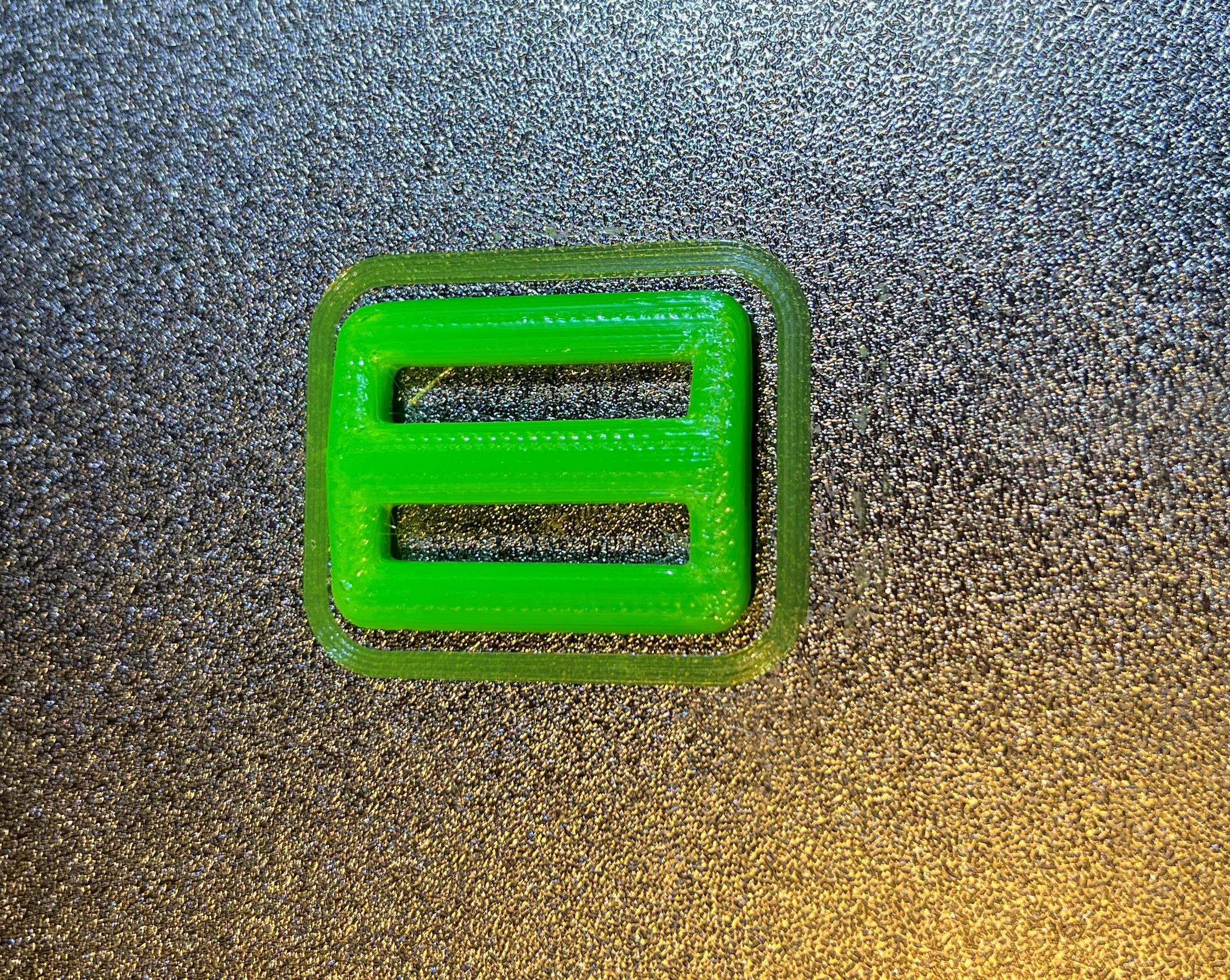
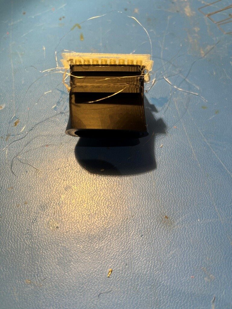
Here’s a couple of photos of my test print. It is a box with cutouts for chassis-mounted USB-C female sockets; the body was printed in green PETG, and the supports were printed in black PLA.
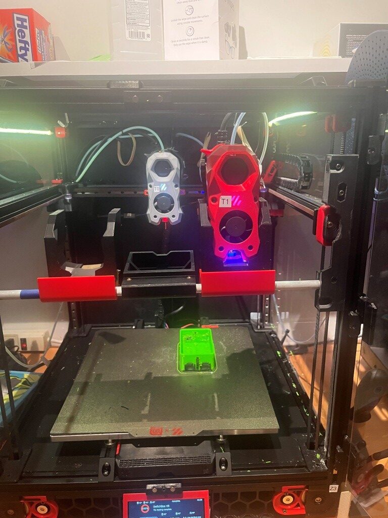
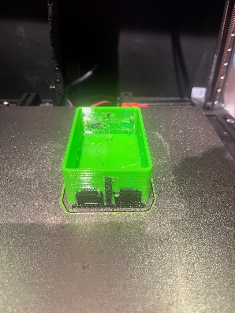
Of course, my ultimate goal is still to be able to do prints that require water-soluble support material, but the above project at least demonstrated that the two-toolhead MissChanger mod – or at least my version of it, can handle dual-material prints.
03 December 2025 Update:
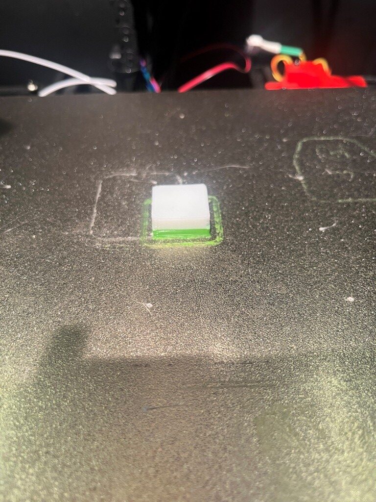
Made my first water-soluble support print today – yay! I printed the bottom part of one of my caplet dispensers, as shown in the screenshot below:
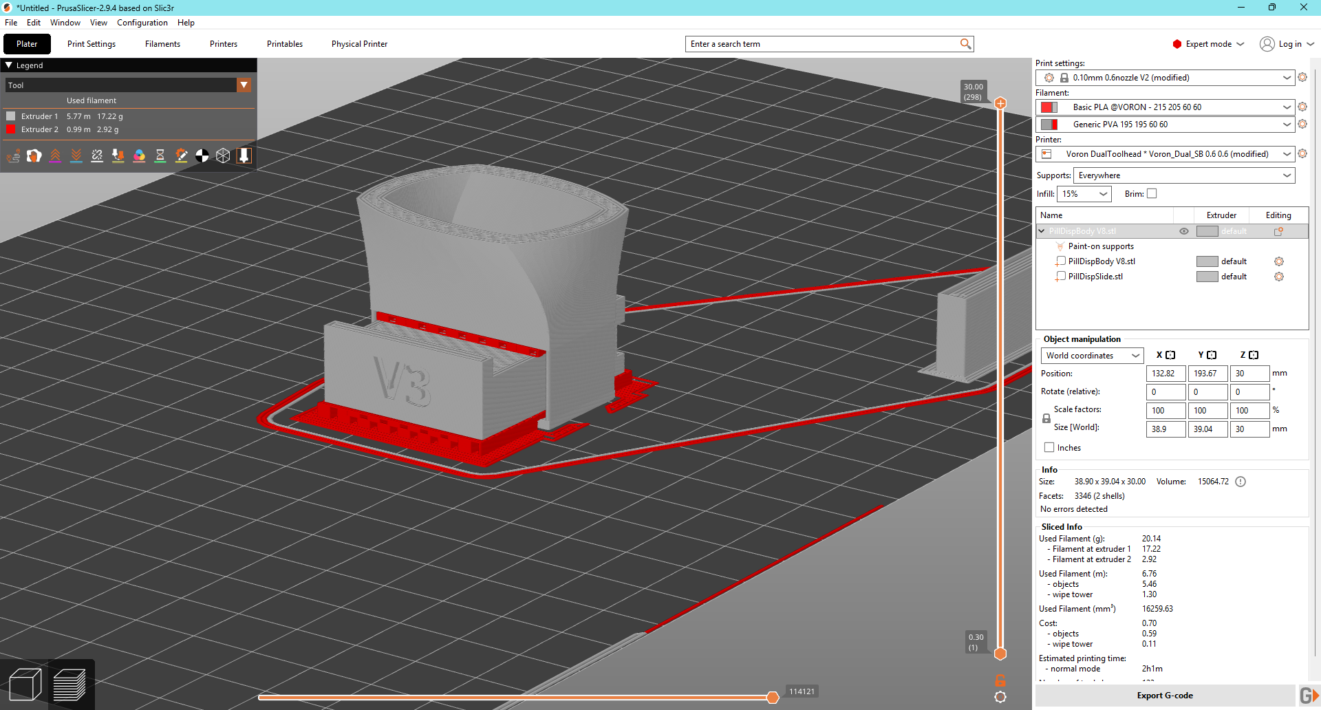
And here is the result:
07 December 2025 Update:
After running into yet more problems with getting a good ‘squish’ on T1 (and spending WAY too much time working with Grok to no real result), today I went back to Vin’s instructions and went through the entire thing again, carefully.
In preparation for this I changed out the PVA soluble filament for PETG to eliminate any issues associated with the rather flexible and sometimes cantankerous PVA. Then, starting with 4.3. Calibrate offsets .
The first step is PROBE_CALIBRATE. This is the normal ‘paper test’ z-offset calibration, a step I have become very familiar with.
4.3.2. Calibration probe setup: This describes the process of setting up the LUBE_BALLS calibration probe, which I had already done. The description is a bit confusing because Vin also talks about another type of physical offset probe called a ‘Nudge Probe’, so I had to keep working around that issue. Another confusing factor is the need to keep removing and replacing the calibration probe. It can’t be on the bed when doing a QGL, and a QGL is required before doing most steps – ugh!
The steps for validating the calibration probe and calibrating T0, which is then used as the reference for all other toolheads:
- Go to
printer.cfgand record thez-offsetfor[tool_probe T0], which should be at (or near) the bottom of the file - Mount tool-head T0 and make sure it’s nozzle is clean
- !!! MAKE SURE THE CALIBRATION PROBE IS NOT MOUNTED !!!
- Run
G28andQUAD_GANTRY_LEVEL - Mount the calibration probe to the bed.
- Run
CALIBRATE_TRIGGER_BOTTOM. If it is a fresh calibration probe, it is worth redoing this step until the suggested value is consistent at +/- 0.005mm. - Copy the proposed offset on the console to the
trigger_to_bottom_z:in[tools_calibrate]. - Save and restart
- Run
CALIBRATE_OFFSETS TOOL=0– But, DON’T RESTART - Check if proposed z-offset to be +-0.01mm of the recorded
z_offsetin step 1. - Run
CALIBRATE_OFFSETS TOOL=02-3 more times to make sure the measured value is consistent.
The above procedure made a lot more sense today than it did in the past. Maybe I had to struggle for a while and then come back to this from a fresh perspective, kinda like letting go of that NYT Sunday Crossword at midnight, getting some sleep, and coming back to it the next day.
4.3.3. Other tool-head(s):
This is where I got lost before, as I just didn’t understand the strategy being pursued. The idea is to make sure the LUBE_BALLS calibration assembly (probe) is working by using it to calibrate the offsets for T0, and then use the T0 results as the reference for all other toolheads. The magic that makes this work is a macro called CALIBRATE_OFFSETS, which starts by running T0 against the LUBE_BALLS cal probe, and then automatically running each subsequent toolhead T1 through TN against the same probe, thereby establishing the X, Y & Z offsets of all the other toolheads relative to T0. These offsets are then stored in the gcode_x/y/z_offset variables in the [tool T(n)] section in the SAVE_CONFIG area of printer.cfg. If CALIBRATE_OFFSETS is called with a ‘TOOL=N’ argument, then only T0 and TN are calibrated. If CALIBRATE_OFFSETS TOOL=0 is used, only T0 is calibrated as is done in step 9 above.
After doing all this, I wound up with the following offsets for T1:
|
1 2 3 4 |
#*# [tool T1] #*# gcode_x_offset: -0.101562 #*# gcode_y_offset: -0.195312 #*# gcode_z_offset: -0.120000 |
Amazingly enough, this setup resulted in a ‘perfect’ (or at least ‘damned good’) first layer, using my first-layer adjustment test print, shown below:
After this was successful, I replaced the PETG on T1 with my brand-new roll of SainSmart PVA, and tried my partial pill dispenser test print (shown above) again. This time the first PVA layer was as good as I have ever seen for a PVA layer, and the entire print continued without fail (The PVA supports inside the open cavity of the slide part did get loose about halfway through the print, but that wasn’t due to any calibration problem – just PVA not sticking completely to PVA. See the following gallery of print photos:
So at this point I believe I have essentially completed the journey to add a second toolhead to my Voron 2.4/300 3D printer – what a ride!