
Posted 18 July 2017,
In my last post on this (somewhat long-winded) subject, I described the implementation of a Teensy-based sweep generator utility for use in testing the band-pass filter (BPF) application, and showed some results from the 52Hz version of the BPF. As a result of this work, I believe I had validated both the test instrumentation and the 52Hz BPF implementation.
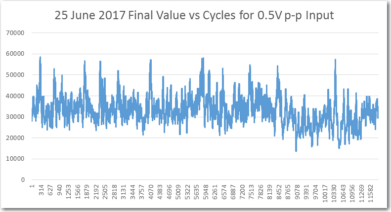
This post extends the previous work to the original goal for this project – the 520Hz BPF implementation. When I did the original work on the 520Hz version, it was clear there was something wrong, but not what. For reference, here are some representative plots from this 24 June 2017 post.
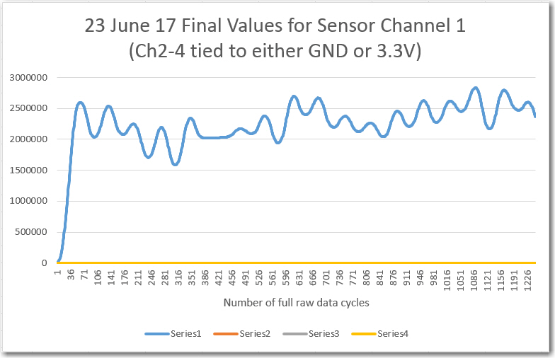
Computed final values vs complete input data cycles for sensor channel 1
There has been a lot of water over the dam between the 24 June post and now.
- Replaced Trinket-based square-wave generator with Teensy 3.5 one for better frequency stability/accuracy
- Replaced simple square-wave generator with frequency/amplitude sweep generator
- Added ’round-trip’ measurement capability. Sweep generator -> BPF -> sweep generator so BPF response can be directly correlated to sweep generator output.
- Revised BPF code to eliminate all but one sensor channel
- Replaced all in-line printouts with writes to internal arrays, with post-run printout option.
- Added micro-second accuracy time stamps to demodulator internal data capture
- Temporarily reduced filter center freq from 520Hz to 52Hz to eliminate any possibility of timing problems due to Teensy 3.5 internal interrupts.
As the plots from the previous post showed, the 52Hz BPF implementation works as intended. So, it was time to try my hand (again!) with the 520Hz version. First, I did an elapsed time study, to make sure no sample periods were being missed. As the plot below shows, all the elapsed time values are reasonable, with only a few going to 101 μSec. I speculate that the 101 values may be due to execution of extra-long internal Teensy ISRs. The elapsed time plot conclusively demonstrates that something I did during the above list of changes eliminated the occasional (1 out of 68 or 69 cycles) missed sample that caused the previous ‘crappy’ results for the 520Hz version of the filter. My personal favorite for the culprit is one or more of the print statements I had in the original code for debugging.
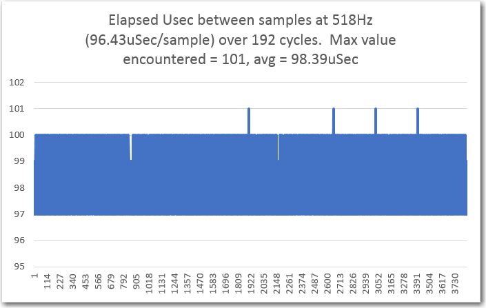
Sample times vs time.
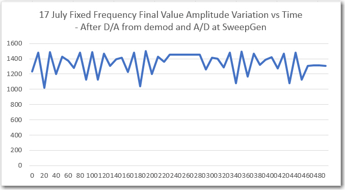
The next set of plots shows the results of an amplitude sweep, with the amplitude set to a fixed 50% p-p value
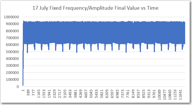
‘raw’ Final Values vs time, with fixed frequency, 50% p-p
’round-trip’ Final Values vs time, fixed freq, 50% p-p
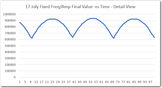
detail of ‘raw’ pot
The above plots weren’t quite what I expected; both the ‘raw’ and ’round-trip’ final values were lower than expected, and the ‘raw’ plot had a lot more ripple than I wanted to see. This all led me to believe that the test frequency was not centered in the BPF passband. I had not actually double-checked this, so I went back a few steps and made sure the fixed amplitude sweep frequency was indeed synched with the demodulator sampling frequency. After that, the plots got a lot cleaner, as shown below.
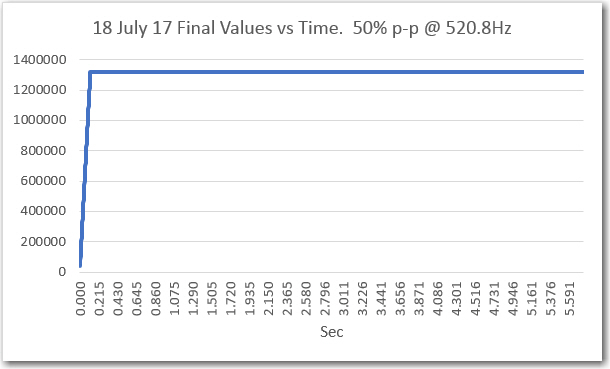
‘raw’ final values vs time after synching Tx & Rx frequencies
In the above plot, the ‘raw’ final value is pretty steady around the value 1,320,000, which agrees well with a 50% p-p Tx level.
Next, I ran frequency sweeps, as shown in the following plots
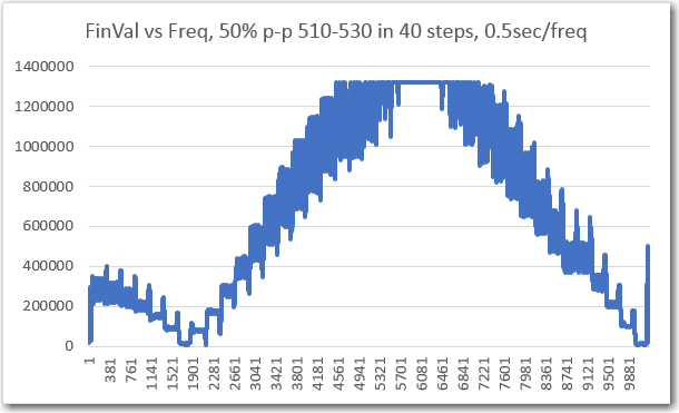
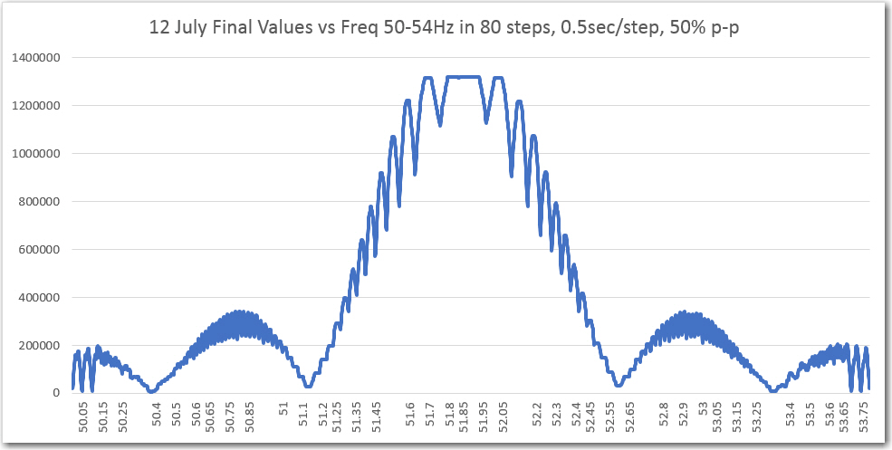
‘raw’ Final Values vs frequency, with amplitude @ 50% p-p
’round-trip’ Final Values vs frequency, with amplitude @ 50% p-p
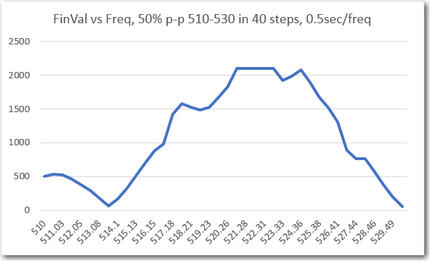
For reference, the same two plots for the 52Hz implementation are shown below
Captured ‘raw’ final value from IR demodulator. Frequency values added later
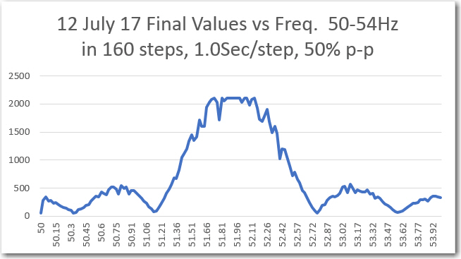
Frequency sweep results from sweep generator printout (D/A from IR demod, then A/D in sweep gen)
Next, I ran an amplitude sweep from 0% to 100% p-p input, as shown in the following plots
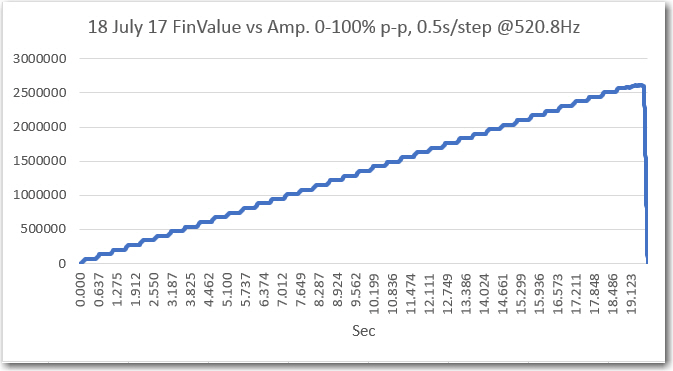
‘raw’ Final Values vs amplitude, with frequency @ 520.8Hz
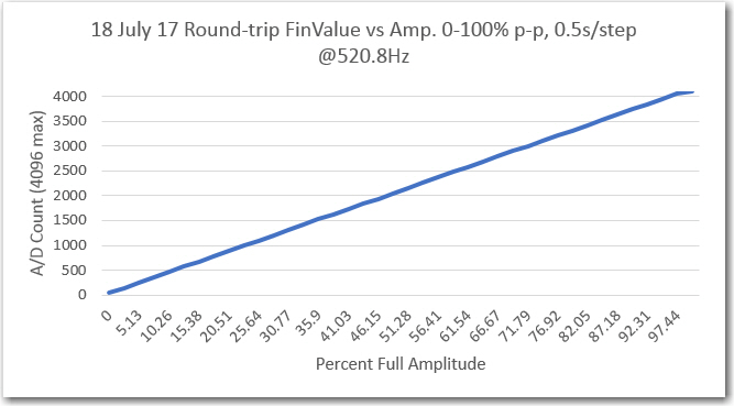
’round-trip’ Final Values vs amplitude, with frequency @ 520.8Hz
So, it appears to me that the 520Hz BPF is working just as well as the 52Hz one, and it’s time to move on to multi-sensor operation.
I have placed the code for the now working 52/520Hz single-channel N-path BPF on GitHub at https://github.com/paynterf/SqWaveIQDemodV2.git. There are three branches available on GitHub, as follows:
- Master – this is the original ‘root’ for the IQ Demodulator (BPF) project
- SingleChannel – this is the final code for the single channel version, working at 52 & 520Hz
- TwoChannel – this is my new branch to host the in-progress dual-channel BPF.
Stay tuned!
Frank