Posted 24 August 2020, 1402 days into the Covid-19 Lockdown
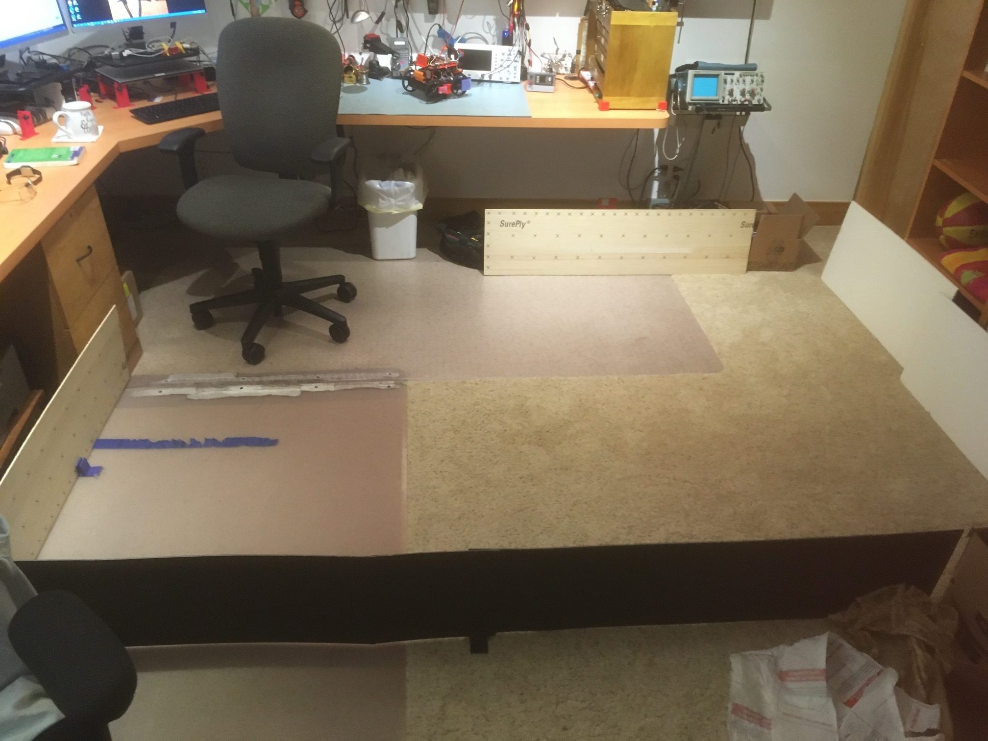
My autonomous wall-following robot Wall-E2 is now smart enough to reliably follow walls and connect to a charging station, at least in my office ‘sandbox’ testing area, as shown in the following video
However, as can be seen toward the end of the video, Wall-E2 had some trouble and almost got stuck making the third 90 degree turn. Apparently the current thin 90mm wheels just don’t provide enough traction on carpet.
So, I decided to see what I could do about re-wheeling Wall-E2. After some research I found there are now plenty of larger diameter wheels for robots out there, but I couldn’t seem to find a set that would fit Wall-E2 and still allow me to keep the current set of wheel guards. I needed the same (or maybe slightly larger) diameter for ‘road’ clearance, but something less than about 20 mm thick to fit within the current wheel guard dimensions. Then it occurred to me while reading the specs for one of the wheels (ABS for the wheel, and TPU for the tire) that I already had two 3D printers standing around waiting for something to do, and I had a plentiful supply of ABS (or in my case, PETG) and TPU filaments – why not build my own? After all, how hard could it be? As you might guess, that question started what now feels like a 10-year slog through ‘3D printed wheel hell’
I wanted to create a spoked wheel with a hub that would accept a 3mm flatted motor shaft, and I wanted to fit this wheel with a simple TPU treaded tire. The wheel would have small ‘guard rail’ rims that would keep the tire from sliding off.
It started innocently enough with a search through Thingiverse, where I found several SCAD scripts for ‘parameterized’ wheels. Great – just what the doctor ordered! Well, except that the scripts, which may have worked fine for the authors, didn’t do what I wanted. and as soon as I tried to adjust them to fit my design specs, I discovered they were incomplete, buggy, or both.
I had wanted to learn a bit more about SCAD anyway and this seemed like a good project to do that with, so I persevered, and eventually came up with a SCAD design that I liked.
I started with bioconcave’s ‘Highly Modular Wheel_v1.0.scad’ file from Thingiverse, and (after what seemed like years trying to understand what was going on) was able to extract modular pieces into my own ‘FlatTireWheel’ scad script, as follows:
/*
The wheel is defined as having a hub, a rim, and a tire. Wheel dimensions are overall diameter
and width, i.e. a 100mm x 30mm wheel will be a cylindrical shape with an overall diameter of 100mm
and a height (width) of 30mm. The rim will be a hollow cylinder with ID = overall diam - tire
thickness - rim thickness, and OD = ID + rim thickness. The cylindrical area between the center of
the wheel and the ID of the rim may be solid or spoked, and there may or may not be a hub.
*/
$fn=150;
wheelDiameter = 90; //overall diameter of the wheel, including rim & tire
wheelWidth = 15; //overall width (height) of the wheel, including guardrails
rimThickness = 5; //rim thickness (part of overall tire diameter)
tireThickness = 5; //tire thickness (part of overall tire diameter)
guardrailThickness = 2; //doesn't add to overall tire diameter
guardrailWidth = 1; //included in overall tire width
spokeThickness = 9;
numberOfSpokes = 3;
spokeEccentricity = 1.5; //how elliptical do the spokes look
//derived values
wheelMinusRimDiameter = wheelDiameter - rimThickness;
rimOD = wheelDiameter - tireThickness;
rimID = rimOD - rimThickness;
// The hub
includeHub = true; // Set to false to remove the hub and only include the shaft diameter hole.
hubDiameter = 15; // The diameter of the hub portion of the wheel
hubHeight = 18; // The total height of the hub
hubZOffset = -wheelWidth/2; // The Z position of the hub, negative numbers from the surface of the wheel
innerCircleDiameter = 0; // The diameter of the solid inner circle under the hub, or zero for none.
baseFilletRadius = 2; // The radius of the fillet (rounded part) between the hub and wheel.
topFilletRadius = 2; // The radius of the fillet (rounded part) at the top of the hub.
chamferOnly = false; // Set to true to use chamfers (straight 45-degree angles) instead of fillets.
concavity = [0,0];
//hardware
shaftDiameter = 4.5; // The diameter of the motor shaft
shaftFlatDiameter = 3.5 ; // The diameter of the motor shaft at the flat, or shaftDiameter for no flat.
setScrewCount = 1; // The number of set screws/nuts to render, spaced evenly around the shaft
setScrewDiameter = 3; // The diameter of the set screw. 3 is the default for an M3 screw.
setScrewTrap = [5.4, 2.3]; // Size [indiameter, thickness] of set screw nut. The depth is set automatically.
setScrewNutDiameter = 5.4; // The "diameter" of the captive nut, from flat to flat (the "in-diameter")
setScrewNutThickness = 2.3; // The thickness of the captive nut
setScrewNutOffset = 0; // The distance to offset the nut from the center of the material. -/+ = in/out
servoHoleDiameter = 0; // The diameter of servo arm hounting holes, or zero if no holes
servoHoleDistance1 = 25; // Distance across servo horn from hole to hole (0 to ignore)
servoHoleDistance2 = 21; // Distance across servo horn from hole to hole, rotated 90 degrees (0 to ignore)
servoArmRotation = 45; // The total rotation of all servo holes
servoNutTrap = [4,1.6]; // Size [indiameter, depth] of servo arm captive nut, or 0 (any) for none.
outerNutTrap = [12.5,0]; // Size [indiameter, depth] of a captive nut, or 0 (any) for none.
wheel_with_tire();
if ( includeHub )
{
translate([0,0, hubHeight/2 + wheelWidth/2 + hubZOffset - concavity[0]])
hub(hubHeight, hubDiameter, shaftDiameter, shaftFlatDiameter,
setScrewCount, setScrewTrap, setScrewDiameter, setScrewNutOffset,
hubZOffset, baseFilletRadius, topFilletRadius, chamferOnly);
}
/////////////////////////////////////////////////////////////////////////////
// Modules...
/////////////////////////////////////////////////////////////////////////////
// The hub (the part that holds the wheel onto the motor
module hub( height, diameter, shaftDiameter, shaftFlatDiameter, nuts, nutSize, setScrewDiameter,
setScrewNutOffset=0, hubZOffset=0, baseFilletRadius=0, topFilletRadius=0, chamferOnly=false) {
hubWidth=(diameter-shaftDiameter)/2;
union() {
difference() {
// Main hub shape
union() {
difference() {
union() {
cylinder( h=height, r=diameter/2, center=true );
// First chamfer the base...
translate([0,0,hubZOffset])
rotate_extrude()
translate([diameter/2,-(height/2)-hubZOffset,0])
polygon(points=[[0,0],[0,baseFilletRadius],[baseFilletRadius,0]]);
}
// Chamfer the top...
rotate_extrude()
translate([diameter/2,height/2,0])
polygon(points=[[0.5,0.5],[-topFilletRadius-0.5,0.5],[0.5, -topFilletRadius-0.5]]);
// Carve the bottom fillet from the chamfer
if ( !chamferOnly ) {
translate([0,0,hubZOffset])
rotate_extrude() {
translate([(diameter/2)+baseFilletRadius,
-(height-(2*baseFilletRadius))/2-hubZOffset,0]) {
circle(r=baseFilletRadius);
}
}
}
}
// Add the fillet back on top of the top chamfer
if (!chamferOnly) {
rotate_extrude() {
translate([
(diameter/2)-topFilletRadius,
(height-(2*topFilletRadius))/2,
0])
circle(r=topFilletRadius);
}
}
}
// Remove the bore
echo(str("shaftDiameter = ", shaftDiameter));
difference()
{
cylinder( h=height+1, r=shaftDiameter/2, center=true );
translate([(shaftDiameter-shaftFlatDiameter+1)/2 + (shaftDiameter/2)
- (shaftDiameter - shaftFlatDiameter),0,0])
cube( [shaftDiameter-shaftFlatDiameter+1,shaftDiameter,height+2], center=true );
}
// Remove the captive nut
//08/22/20 gfp bugfix: chg translate() z param to zero so it follows hub offsets
//08/22/20 gfp bugfix: repl 'boreDiameter' with 'shaftDiameter' to reduce confusion
for( i=[0:nuts-1] )
{
rotate([ 0,0, (360/nuts)*i ])
translate([shaftDiameter/2+(diameter-shaftDiameter)/4 +setScrewNutOffset,
0, 0])
{
rotate([0,-90,0])
{
captiveNut( nutSize, setScrewDiameter,
depth=height/2+1, holeLengthTop=hubWidth/2+setScrewNutOffset
+(shaftDiameter-shaftFlatDiameter),
holeLengthBottom=hubWidth+baseFilletRadius-setScrewNutOffset);
}
}
}
}
}
}
module wheel_with_tire()
{
difference()
{
union()
{
cylinder(wheelWidth, rimOD/2, rimOD/2, $fn=150);
cylinder(guardrailWidth,
guardrailThickness + rimOD/2,
guardrailThickness + rimOD/2,
$fn=150);
translate(v=[0,0,wheelWidth-guardrailWidth])
{
cylinder(guardrailWidth,
guardrailThickness + rimOD/2,
guardrailThickness + rimOD/2,
$fn=150);
}
}
translate(v=[0,0,-2])
{
cylinder(wheelWidth+4, rimID/2, rimID/2, $fn=150);
}
//08/22/20 remove setscrew access hole
//extend the hub shaft capture screw hole out past rim, so that
//it will pierce the rim if the hub sits low enough on the rim
if ( includeHub )
{
nutSize=setScrewTrap;
translate([0,0, hubHeight/2 + wheelWidth/2 + hubZOffset])
hubHoleCutout(hubHeight, hubDiameter, shaftDiameter, shaftFlatDiameter,
setScrewCount, setScrewTrap, setScrewDiameter, setScrewNutOffset,
hubZOffset, baseFilletRadius, topFilletRadius, chamferOnly);
}
}
if(numberOfSpokes > 0)
{
difference()
{
for (step = [0:numberOfSpokes-1])
{
rotate( [0, 0, step*(360/numberOfSpokes)] )
ellipticalSpoke(wheelWidth, wheelMinusRimDiameter, spokeEccentricity);
}
// Remove the motor shaft and setscrew nut trap cutouts if necessary
if(includeHub)
{
union()
{
//flatted motor shaft cutout
difference()
{
cylinder( h=(wheelWidth+hubHeight) + 2, r=shaftDiameter/2, center=true );
translate([(shaftDiameter-shaftFlatDiameter+1)/2 + (shaftDiameter/2)
- (shaftDiameter - shaftFlatDiameter),0,0])
cube( [shaftDiameter-shaftFlatDiameter+1,shaftDiameter,10*hubHeight+2], center=true );
}
//setscrew nut trap cutout
//08/22/20 gfp bugfix: chg translate() z param to zero so it follows hub offsets
//08/22/20 gfp bugfix: repl 'boreDiameter' with 'shaftDiameter' to reduce confusion
// for( i=[0:nuts-1] )
{
hubWidth=(hubDiameter-shaftDiameter)/2;
// rotate([ 0,0, (360/nuts)*i ])
// translate([shaftDiameter/2+(hubDiameter-shaftDiameter)/4 +setScrewNutOffset,
// 0, 0])
translate([shaftDiameter/2+(hubDiameter-shaftDiameter)/4 +setScrewNutOffset,0, hubHeight/2 + wheelWidth/2 + hubZOffset])
{
rotate([0,-90,0])
{
echo(str("captiveNut(",
setScrewTrap,
",",setScrewDiameter,
",",hubHeight/2+1,
",",hubWidth/2+setScrewNutOffset
+(shaftDiameter-shaftFlatDiameter),
",",hubWidth+baseFilletRadius-setScrewNutOffset,") call in spoke"));
captiveNut( setScrewTrap, setScrewDiameter,
depth=hubHeight/2+1, holeLengthTop=hubWidth/2+setScrewNutOffset
+(shaftDiameter-shaftFlatDiameter),
holeLengthBottom=hubWidth+baseFilletRadius-setScrewNutOffset);
}
}
}
}
}
//08/22/20 remove setscrew access hole
//extend the hub shaft capture screw hole out past rim, so that
//it will pierce the rim if the hub sits low enough on the rim
if ( includeHub )
{
hubWidth=(wheelDiameter-shaftDiameter)/2;
nutSize=setScrewTrap;
translate([0,0, hubHeight/2 + wheelWidth/2 + hubZOffset])
hubHoleCutout(hubHeight, hubDiameter, shaftDiameter, shaftFlatDiameter,
setScrewCount, setScrewTrap, setScrewDiameter, setScrewNutOffset,
hubZOffset, baseFilletRadius, topFilletRadius, chamferOnly);
}
}
}
}
module hubHoleCutout( height, diameter, boreDiameter, shaftFlatDiameter, nuts, nutSize, setScrewDiameter,
setScrewNutOffset=0, hubZOffset=0, baseFilletRadius=0, topFilletRadius=0, chamferOnly=false)
{
hubWidth=(diameter-boreDiameter)/2;
union()
{
// Remove the captive nut
for( i=[0:nuts-1] )
{
rotate([ 0,0, (360/nuts)*i ])
// translate([boreDiameter/2+(diameter-boreDiameter)/4 +setScrewNutOffset,
// 0, height/2 - (height+hubZOffset)/2])
translate([boreDiameter/2+(diameter-boreDiameter)/4 +setScrewNutOffset,
0,0])
{
rotate([0,-90,0])
{
echo(str("before call to captiveNutHoleExtension(",nutSize, ", ",setScrewDiameter, ", ",depth=height/2+1, ", ",hubWidth/2+setScrewNutOffset
+(boreDiameter-shaftFlatDiameter), ", ",hubWidth+baseFilletRadius-setScrewNutOffset));
//* captiveNut( nutSize, setScrewDiameter,
// depth=height/2+1, holeLengthTop=hubWidth/2+setScrewNutOffset
// +(boreDiameter-shaftFlatDiameter),
// holeLengthBottom=hubWidth+baseFilletRadius-setScrewNutOffset);
captiveNutHoleExtension( nutSize, setScrewDiameter,
depth=height/2+1, holeLengthTop=hubWidth/2+setScrewNutOffset
+(boreDiameter-shaftFlatDiameter),
holeLengthBottom=hubWidth+baseFilletRadius-setScrewNutOffset);
}
}
}
// }
}
}
module ellipticalSpoke(width, diameter, eccentricity)
{
translate([0,0,width/2])
intersection()
{
cylinder(h=width, r=wheelMinusRimDiameter/2, center = true);
translate([spokeEccentricity*wheelMinusRimDiameter/4, 0, 0])
scale([spokeEccentricity,1,1])
{
difference()
{
cylinder(h = width, r = wheelMinusRimDiameter/4, center = true);
//translation and width addition to make sure of good punch-out
translate([spokeThickness,0,0])
cylinder(h = width+4, r = wheelMinusRimDiameter/4, center = true);
}
}
}
}
//circleSpokes( d, wheelWidth, spokeThickness, proportion, numberOfSpokes );
//
//// Circles pattern spokes
//module circleSpokes( wheelDiameter, wheelWidth, spokeThickness, proportion, numberofSpokes ) {
// echo( "Circles Style..." );
// intersection() {
//# cylinder( h=wheelWidth, r=wheelDiameter/2, center = true );
//
// for (step = [0:numberofSpokes-1]) {
// rotate( [0, 0, step*(360/numberofSpokes)] )
// circleSpoke( wheelDiameter, wheelWidth, spokeThickness, proportion );
// }
// }
//
//}
//module circleSpoke( wheelDiameter, wheelWidth, spokeThickness, proportion ) {
//// render()
// echo(str("spokeThickness = ",spokeThickness));
// let( ox=(wheelDiameter/2)*proportion[0], oy=(wheelDiameter/2)*proportion[1] )
// let( ix=ox-(spokeThickness*2), iy=oy-(spokeThickness*2) )
// {
// translate ( [-ox/2, 0, 0] )
// {
// difference()
// {
// scale([proportion[0],proportion[1],1])
//# cylinder( r=wheelDiameter/4, h=wheelWidth, center=true);
// scale([(ix/ox)*proportion[0],(iy/oy)*proportion[1],1])
// cylinder( r=wheelDiameter/5, h=wheelWidth +1, center=true);
// }
// }
// }
//}
// This is the captive nut module I use in several of my designs.
module captiveNut( nutSize, setScrewHoleDiameter=3,
depth=10, holeLengthTop=5, holeLengthBottom=5 )
{
render()
union() {
nut( nutSize );
if ( depth > 0 )
translate([depth/2,0,0])
cube( [depth, nutSize[0], nutSize[1]], center=true );
translate([0,0,-(nutSize[1]/2)-holeLengthBottom])
cylinder(r=setScrewHoleDiameter/2, h=nutSize[1]+holeLengthTop+holeLengthBottom, $fn=15);
}
}
// nutSize = [inDiameter,thickness]
module nut( nutSize ) {
side = nutSize[0] * tan( 180/6 );
if ( nutSize[0] * nutSize[1] != 0 ) {
for ( i = [0 : 2] ) {
rotate( i*120, [0, 0, 1])
cube( [side, nutSize[0], nutSize[1]], center=true );
}
}
}
// This extends the captive nut hole so through the wheel rim for tool access
module captiveNutHoleExtension( nutSize, setScrewHoleDiameter=3,
depth=10, holeLengthTop=5, holeLengthBottom=5 )
{
translate([0,0,-wheelDiameter/2])
cylinder(r=1+setScrewDiameter/2, h=wheelDiameter/2, $fn=15);
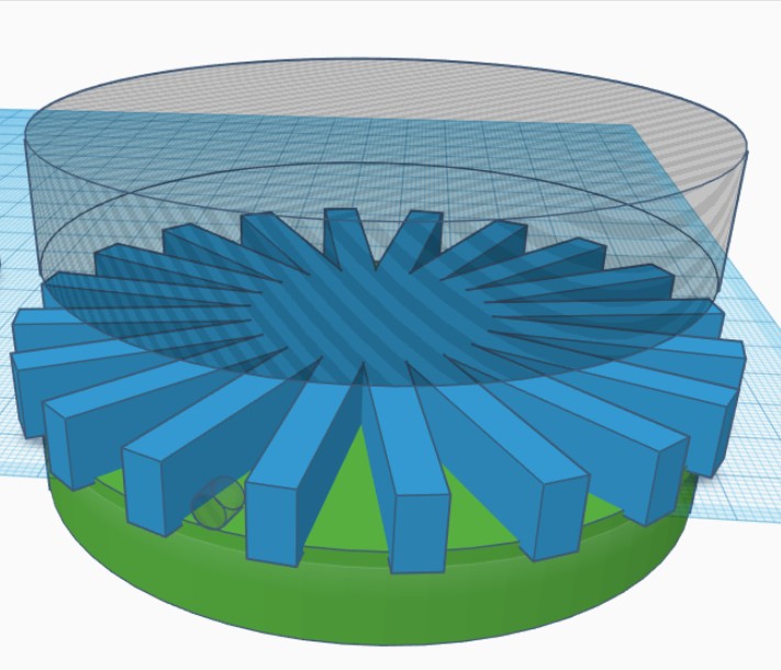
}Here’s a screenshot of a completed 86mm wheel with elliptical spokes and a hub compatible with a 3mm flatted shaft. When a TPU tire is added to the rim, the assembly should be about 90mm in diameter.
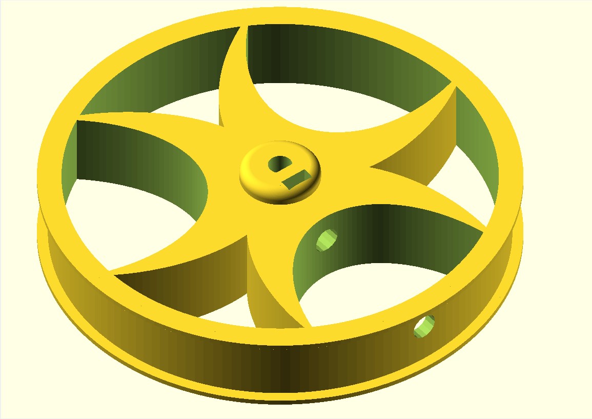
One of the many issues I had with the original code is it assumed the hub would sit on top of the spokes, and therefore there was no need to worry about whether or not the setscrew arrangement would be blocked by the spokes and/or rim. Since I wanted a wheel that was mostly tread, I wanted to ‘sink’ the hub into the spokes as shown above. In order to make this work, I needed to extend the setscrew access hole through the spoke assembly and through the rim. In the finished design, the hub assembly can be moved freely up and down in the center of the wheel, and the hole extensions will follow. If the hub setscrew hole isn’t blocked by the spokes and/or rim, then the extensions don’t do anything; otherwise they extend the setscrew hole as shown above.
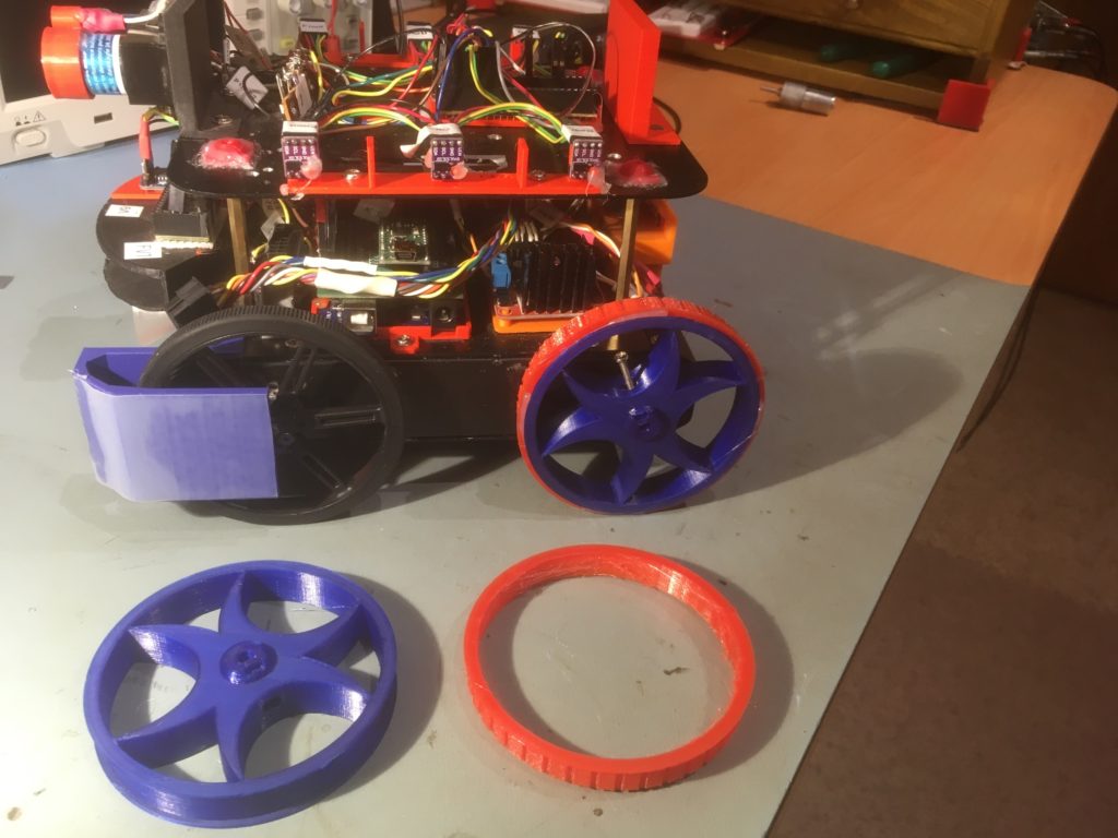
Here’s a photo of separate wheel/tire pieces, and a completed wheel/tire combination on Wall-E2
2 September 2020 Update:
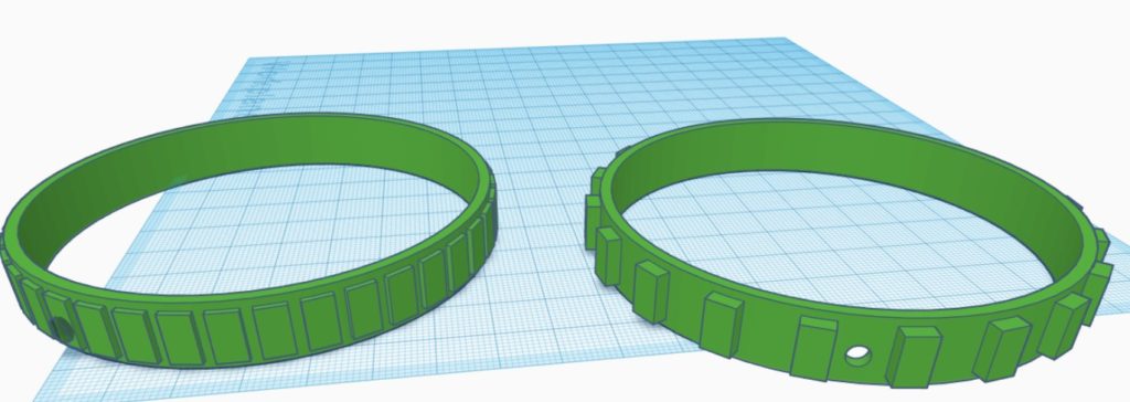
After running some sandbox tests with my new wheels, I discovered that the new tires didn’t have much more traction than the old ones. However, now that I ‘had the technology’, it was a fairly simple task to design and print new tires to fit onto the existing new rims. Rather than do the tire design in SCAD, I found it much much easier to do this in TinkerCad. Here’s a couple of screenshots showing the TCad design.
03 September 2020 Update:
The increased traction provided by the new tires have caused a new problem; on a hard surface the rotation during a ‘spin turn’ (one side’s motors going forward, the other going in reverse) is too fast, causing the robot to slide well past the target heading. Not so much of a problem on carpet, but how would the robot know which surface is in play at the moment. After some thought, I decided to try and modulate the turn rate, in deg/sec, as a proxy for the surface type. So, in ‘SpinTurn()’ I put in some code to monitor the turn rate and adjust the motor speeds upward or downward to try and keep the turn rate at a reasonable level.
Here’s a video of a recent run utilizing the new ‘SpinTurn’ rate modulation algorithm
And the data from the three ‘spin turn’ executions, one on hard surface, and two on carpet.
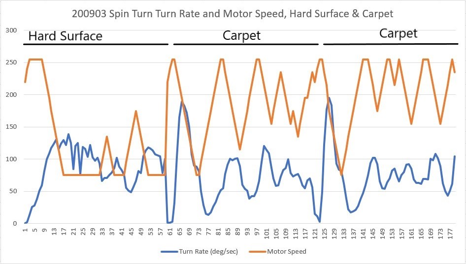
As can be seen in the above video and plots, the motor speeds used on the hard surface turn is much lower than the speeds used during the carpet turns, as would be expected. This is a much nicer result than the ‘fire and forget’ algorithm used before. Moreover, the carpet turns are much more positive now thanks to the more aggressive tread on the new tires – yay!