Posted 07 September 2020,
I’ve been having some ‘issues’ with driving Wall-E2’s Pololu 20D 125:1 12V metal geared motors with the old L298N motor drivers, so I thought it was time to replace them with the Adafruit DRV8871 models used in ‘re-motoring’ my two-wheel robot (see this post for some of the details).
The first step was to review the work I had done earlier replacing the L298N on my two-wheel robot with the same DRV8871 Driver. The two-wheel robot uses a UNO controller, while Wall-E2 uses a Mega, but they are similar enough so porting the wiring and code should be simple enough. The two-wheel robot uses UNO pins 5, 6, 9 & 10 (all PWM lines) for direction and speed control, while Wall-E2 uses pins 8-13 and 36, 38, 40, 42, 44 & 46 for controlling the two L298N motor drivers. My plan is to try using just two motor drivers, one for both left motors, and another for both right motors. If this works, I’ll need just 4 lines, say 8-11 (If I later need to use four drivers vs two, I’ll use 12/13 for one of the ‘extras’ and 6/7 for the other one. Currently 6 is unused and 7 drives the red laser diode, so moving it shouldn’t be a big problem).
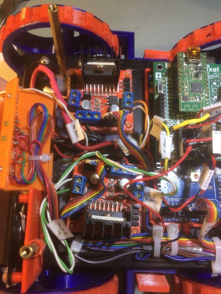
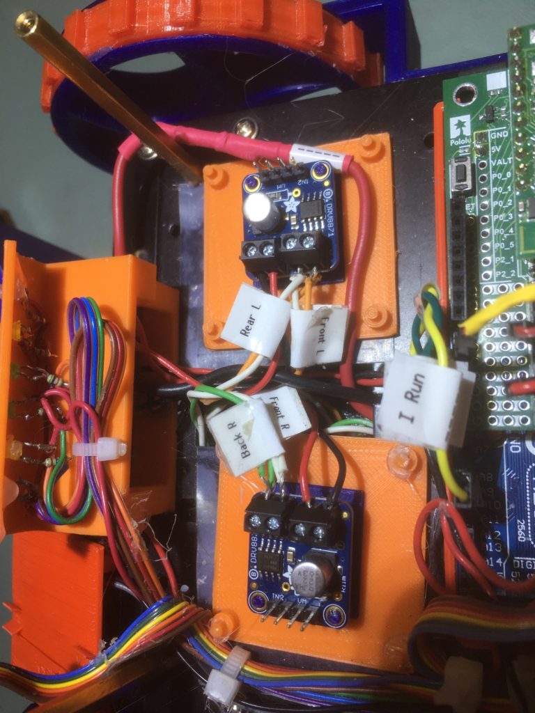
So, I replaced the two L298N modules with two DRV8871 modules, and wired both left motors into one driver and both right motors into the other, as shown in the following photos
Since I previously replaced an L298N with a DRV8871 in my two-wheel robot, I had already modified all the relevant motor driver code to use the DRV8871 module vs the L298N, so all I had to do was replace the low-level motor interface modules in my four-wheel robot project with the corresponding ones from my two-wheel robot project. The replaced modules were:
- SetLeftMotorDirAndSpeed
- SetRightMotorDirAndSpeed
- StopBothMotors
- MoveAhead
- MoveReverse
Note that the four-wheel robot code uses separate SetLeft/RightMotorDir & SetLeft/RightMotorSpeed functions, so these needed to be modified or replaced.
SetLeft/RightMotorSpeed() is called from RunBothMotors() & SpinTurn(). I could modify SpinTurn() to call RunBothMotors() instead of calling SetLeft/RightMotorSpeed() directly.
RunBothMotors() is called from RunBothMotorsMsec(), Setup(), MoveReverse() and MoveForward(). Every call to RunBothMotors() is paired with calls to SetLeft/RightMotorDir(), so I could replace Each set of calls with a single call to SetLeft/RightMotorDirAndSpeed(). The only issue with this are the RunBothMotorsMsec() calls in Setup() & ExecDisconManeuver().
I decided to modify the RunBothMotors() & RunBothMotorsMsec() functions to take a direction parameter, and then the functions will simply call SetLeft/RightDirAndSpeed().
10 September 2020 Update:
I got lost in the details of the Wall-E2 code, so I decided to simplify things to check out the new DRV8871-based motor setup. I modified my original ‘Adafruit_DRV8871_Driver_Test’ project to run both motor sets forward and backward from the minimum PWM value (about 50) to max (255) while monitoring the total current for all four motors, as shown in the following Excel plot
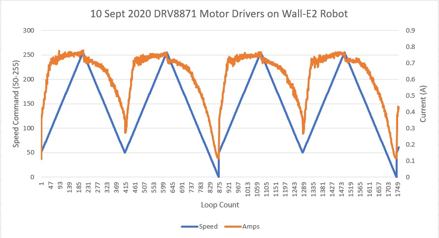
As can be seen from the above plot, the total motor current for all four motors is right around 0.8A or about 0.4A per driver – well within the current limits for the DRV8871 module. As a side note, the TO-3 cans on the modules barely got warm, so this looks like a real winner.
Now that I have the technical issues sorted out with respect to the driver replacement project, I can get back to the main project of improving Wall-E2’s wall-following ability.
Stay tuned!
Frank
13 September 2020 Update:
Unfortunately, when I started running the full Wall-E2 code, the right set of motors would go backwards, but not forwards – awkward to say the least. After a lot of troubleshooting, it finally dawned on me that the problem was being caused by my introduction of a TIMER1-based interrupt a while ago to manage ‘stuck’ detection. TIMER1 controls PWM on pins 11 & 12, and one of those pins was being used by the right motor – bummer!
After a LOT of screwing around, I finally decided that the only way to really figure things out was to remove everything but the timer and motor driver code from the program to figure out what timer (if any) I can use for the ‘stuck’ detection interrupt and still have proper motor control.
To that end, I created a new Arduino program ‘TimerISRvsPWMTest.ino’ as shown below:
|
1 2 3 4 5 6 7 8 9 10 11 12 13 14 15 16 17 18 19 20 21 22 23 24 25 26 27 28 29 30 31 32 33 34 35 36 37 38 39 40 41 42 43 44 45 46 47 48 49 50 51 52 53 54 55 56 57 58 59 60 61 62 63 64 65 66 67 68 69 70 71 72 73 74 75 76 77 78 79 80 81 82 83 84 85 86 87 88 89 90 91 92 93 94 95 96 97 98 99 100 101 102 103 |
/* Name: TimerISRvsPWMTest2.ino Created: 9/15/2020 11:25:13 AM Author: FRANKNEWXPS15\Frank Program to test interaction between TIMER1 ISR and PWM for motor control */ #include <PrintEx.h> //allows printf-style printout syntax StreamEx mySerial = Serial; //added 03/18/18 for printf-style printing #pragma region MOTOR_PINS //09/11/20 Now using two Adafruit DRV8871 drivers for all 4 motors const int In1_Left = 8; const int In2_Left = 9; //Right Motors paralleled to left DRV8871 driver const int In1_Right = 10; const int In2_Right = 11; #pragma endregion Motor Pin Assignments #define TIMER_INT_OUTPUT_PIN 31 //scope monitor pin void setup() { Serial.begin(115200); delay(1000); #pragma region I/O PIN SETUP //09/11/20 now using two DRV8871 motor drivers for all four motors pinMode(In1_Left, OUTPUT); pinMode(In2_Left, OUTPUT); pinMode(In1_Right, OUTPUT); pinMode(In2_Right, OUTPUT); #pragma endregion I/O PIN SETUP // #pragma region TIMER_INTERRUPT //08/10/20 added Timer interrupt //set timer1 interrupt at (1000/MIN_PING_INTERVAL_MSEC)Hz 5Hz a/o 08/10/20 cli();//stop interrupts TCCR1A = 0;// set entire TCCR1A register to 0 TCCR1B = 0;// same for TCCR1B TCNT1 = 0;//initialize counter value to 0 // set compare match register for 5hz increments OCR1A = 3124;// = (16*10^6) / (5*1024) - 1 (must be <65536) TCCR1B |= (1 << WGM12);// turn on CTC mode TCCR1B |= (1 << CS12) | (1 << CS10);// Set CS10 and CS12 bits for 1024 prescaler TIMSK1 |= (1 << OCIE1A);// enable timer compare interrupt sei();//allow interrupts pinMode(TIMER_INT_OUTPUT_PIN, OUTPUT); #pragma endregion TIMER_INTERRUPT while (1) { digitalWrite(In1_Right, LOW); digitalWrite(In2_Right, LOW); digitalWrite(In2_Left, LOW); digitalWrite(In1_Left, LOW); delay(1000); digitalWrite(In1_Right, LOW); analogWrite(In2_Right, 128); digitalWrite(In2_Left, LOW); analogWrite(In1_Left, 128); delay(2000); digitalWrite(In2_Right, LOW); analogWrite(In1_Right, 128); digitalWrite(In1_Left, LOW); analogWrite(In2_Left, 128); delay(2000); } } ISR(TIMER1_COMPA_vect) //timer1 interrupt 1Hz toggles pin 13 (LED) { digitalWrite(TIMER_INT_OUTPUT_PIN, HIGH); delayMicroseconds(10); digitalWrite(TIMER_INT_OUTPUT_PIN, LOW); } //ISR(TIMER5_COMPA_vect) //timer1 interrupt 1Hz toggles pin 13 (LED) //{ // digitalWrite(TIMER_INT_OUTPUT_PIN, HIGH); // delayMicroseconds(10); // digitalWrite(TIMER_INT_OUTPUT_PIN, LOW); //} void loop() { } |
With the TIMER1 setup commented out, both motors rotate forwards and backwards no problem. However, as soon as the TIMER1 code was un-commented, the motor driver on pins 10/11 would turn one way but not the other. With an O’scope I could see the PWM waveform on pin 10 but not on pin 11. This is consistent with Timer1 controlling PWM on pins 11,12 & 13.
So, I moved the wire connected to DRV8871 IN2 from 11 to 3 and changed the code to use pins 10 & 3 vs 10 & 11. Now the motor connected to these pins rotates both forward and backwards
Then I went back to my WallE2_V6 project and tried the same trick – moving the IN2 pin from 11 to 3; nope – still doesn’t work. In fact, moving from 11 to any other PWM pin doesn’t work in the WallE2 project, but does in the TimerPWM test project – weird.
So, thinking that maybe there were some timer dependencies hidden in one or more of the libraries being used for the WallE2 project, I copied them all over to the TimerPWM project folder, added them to the project in VS2019, and added them to the project code. After I got everything to compile, I ran the TimerPWM test project successfully using 10 & 7, 10 & 3, 10 & 2, etc (but 10 & 11 still doesn’t work with TIMER1 ISR enabled).
So, it’s not the libraries. Next I changed the timer interrupt code to use TIMER5 instead of TIMER1, moving the pin dependency from 11-13 to 44-46. I confirmed this by changing ‘In1_Right‘ to 44, 45, 46 in turn and moving the physical In1_Right connection to the corresponding pin, noting that the motors don’t rotate properly when driven from any of the affected pins.
Next, I changed the timer interrupt code in WallE2_V6 from TIMER1 to TIMER5 to see if I can get back pin 11 as a PWM pin. Nope – it still doesn’t work in the WallE2 code, nor does pin 7.
Back to the test program. Copied all the ‘pre-setup’ code from WallE2 to the test program; no change – test program still works properly.
After a few back-and-forths of this nature, I eventually narrowed the problem down to the driver modules themselves. A physical inspection revealed that I had forgotten to solder the second pin on both 2-pin screw terminals on one of the drivers – oops! So, like many seemingly intractable technical problems, this one was caused by two independent issues; the use of TIMER1 caused pins 10-12 to be unavailable for motor drive PWM, and the intermittent connections to the left-side motors complicated the symptoms. This was a perfect example of why ‘cutting the problem in half’ (in my case, by eliminating all the Wall-E2 hardware from the problem) is so effective in troubleshooting.
Stay tuned!
Frank