Monthly Archives: July 2022

FlashForge Creator PRO 2 IDEX Filament/Color Designator Project

Posted 29 July 2022

I’ve had my Flashforge Creator PRO 2 IDEX 3D printer for a while now, and ever since Jaco Theron and I got the Prusa Slicer Configuration for this printer working, I have been enjoying trouble-free (as much as any 3D printer is ‘trouble-free’) dual-color printing.

However, there are some ‘gotchas’ that can make using this printer annoying.

  • The way that the FFCP2 filament spools are arranged on the back of the printer means that the filament from the left spool feeds the right extruder, and vice versa, which leads to confusion about which filament feeds what extruder
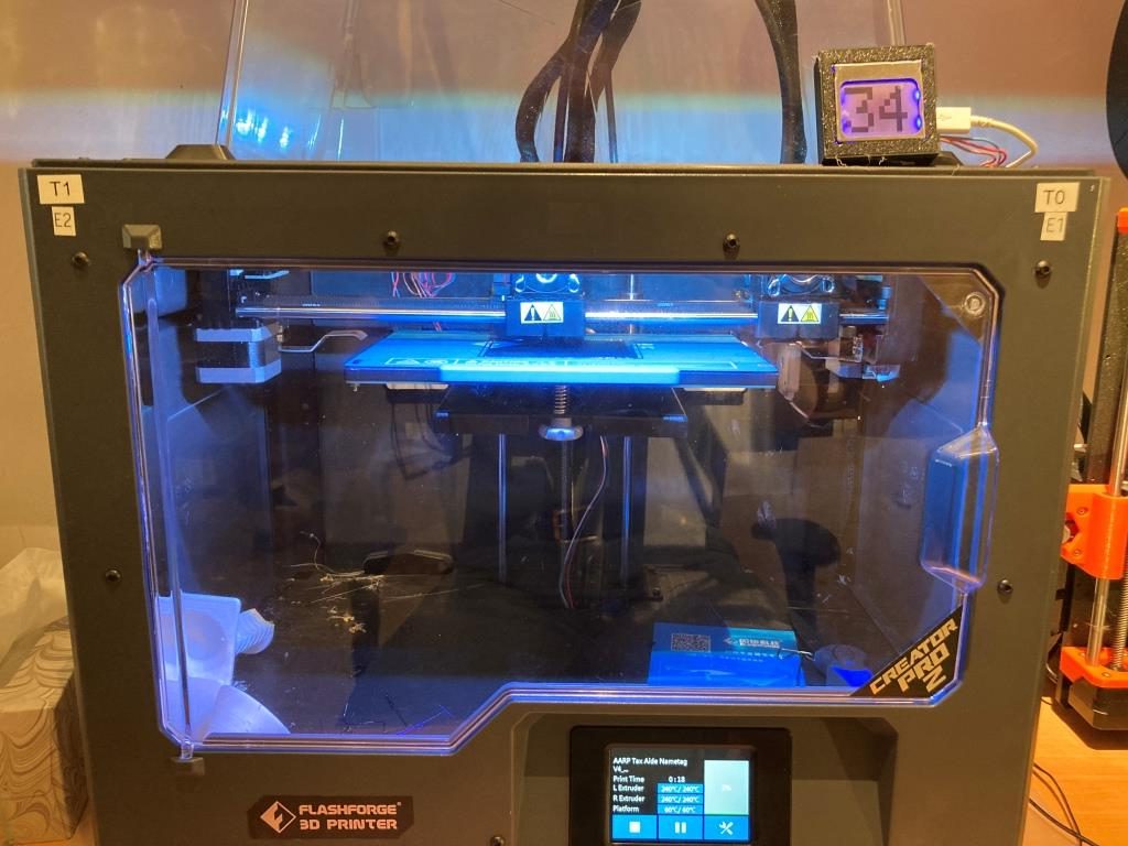
  • The printer configuration in the slicer refers to the left extruder as ‘Extruder 2, the left extruder temperature as ‘T1’, the right extruder as ‘Extruder 1, the right extruder temperature as ‘T0’, so I’m never sure which physical extruder I’m dealing with when setting up for a print.
  • The filament spools are located at the rear of the printer, so it’s impossible to tell what filament type is loaded without physically rotating the whole printer, removing the spool from the holder, and looking at the label. And, since my short-term memory is about equal to that of a amoeba, I wind up doing this multiple times.

So, I decided to see what I could do to ameliorate this issue. The first thing I did was to use my handy-dandy Brother label maker to label the left and right extruders with their respective designations in the software, as shown in the photo below.

The next thing was to use my newly-acquired Blender super-powers to create and install removable filament color/type tags to both sides so I would no longer have to rely on my crappy memory to know what filament type and color was loaded on each side, as shown in the following photo.

Filament type and color tags for each extruder

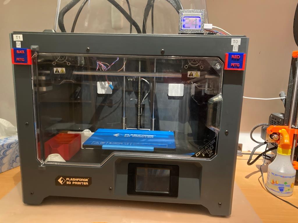
The type/color tags slide into slots in the plate holders, and the plate holders are mounted using the FFCP2′ 4mm hex-head front plate mounting screws. I printed up tags for all my normal colors and filament types and store them inside the printer (the red box seen inside the printer on the left-hand side). Then, when I change a spool, I change the tags to match the new filament type & color.

Additional Work on Wall Tracking Algorithm

Posted 15 July 2022,

After getting everything working (or so I thought) in my sandbox, I started running into problems again with wall tracking. It just wasn’t very smooth at all. So, I decided to create a part-task version of my Wall-E3 code (WallE3_WallTrackTuning.ino) to just tackle PID tuning for left/right wall tracking. this version allows PID and offset values to be entered interactively to facilitate faster tuning. After a number of runs, I wound up with a PID set of (200,20,0). This produce a very nice, smooth tracking behavior.

In addition, I went back through all my code and re-educated myself on exactly how my current wall offset capture algorithm developed and whether or not it was, in fact, what I wanted. I started by diagramming all (I hope) relevant initial orientation and offset cases, as shown in the following Visio chart.

Wall Capture Algorithm Recap

In the above figure, four basic configurations are diagrammed; The first two are for left-side tracking with the robot starting in three different configurations inside the desired 40cm tracking offset, and three more outside the tracking offset. The second two are the same as the first, but for right-side tracking.

The algorithm is based on knowing the robot’s orientation w/r/t the local wall, which is determined by the expression ‘Steer = (Front – Rear)/100’, implemented in the Teensy 3.5 MCU that manages the VL53L0X lidar array. This result is available to the main program as ‘glLeftSteeringVal’ and ‘glRightSteeringVal’. The steering values are proportional to the orientation angle in degrees, calculated as OrientDeg = steerval/0.0175.

Expressions for which way and how much to turn to achieve the desired capture approach angle of +/- 30 degrees were determined for each of the 12 starting configurations shown (numbered 1-12 in the above figure). An examination of the resulting expressions showed that they could be collapsed down into just two different calls to the ‘SpinTurn(isCCW, numdeg)’ subroutine – one for left-side tracking, and one for right-side tracking, as shown by the bold-face expressions above.