Monthly Archives: August 2022

FlashForge Creator PRO 2 IDEX GUI Issues

Posted 30 August 2022

Exactly one year ago I posted about receiving my then-new FlashForge Creator PRO 2 IDEX 3D printer. Since then I have made many successful prints and have been very happy with the machine. Then just a few weeks ago I started having serious problems with prints not sticking to my flexible build plate. Such problems occur regularly with 3D printers, and they are usually fairly easy to troubleshoot and fix, but this time I found that the touch-screen GUI on the FFCP2 IDEX machine to be more of a hindrance than a help in working my way through the problem. This post describes the issues I encountered and some suggested changes to the GUI to resolve them. The firmware used is the latest version, V1.8.

Extruder Z-axis Offset Calibration:

One of the most common problems for non-sticking prints is the extruder Z-axis offset. If the offset is too large, the filament won’t contact the print bed with enough area to adhere the first layer, and this can cause the BOD (ball of death) as the filament balls up around the extruder. When I do this procedure on my Prusa MK3S+ single-extruder printer, the display shows the current offset so adjustments can be made from a known starting position. Unfortunately the FFCP2 GUI for some reason forces the user to calibrate both extruders every time, and starts by setting the offset on both extruders to +2mm, undoubtedly to make sure the nozzles are well away from the print bed. This also erases the existing offset value, so there is no way to slightly ‘tweak’ the offset value one way or the other – the offsets have to be set from the beginning every time. For first-time users, this might be OK, but for experienced printers it is a royal PITA.

Imagine you have done some minor maintenance on the right extruder, but the left extruder is printing perfectly. Now you need to recalibrate the right extruder, but don’t want to mess with your finely-tuned left extruder. Nope – can’t do that. As soon as you select ‘Z axis Calibration’ you are doomed! The offset values for both extruders fly out the window and you are back to using the supplied plastic spacer to calibrate both extruders ‘by feel’. Doesn’t matter that you had that left extruder all dialed in – you are hosed!

Or, maybe you are happily running PETG on both extruders, but now you want to make a print that requires a dissolvable filament, like AquaSys120 or similar. You change out the filament on one extruder and make a test print using just the dissolvable filament and find it either isn’t extruding at all (offset too close to the bed) or more likely isn’t adhering to the bed due to subtle differences in the texture/stickiness of AquaSys120 filament vs PETG. You know the way to fix this is to slowly vary the z-offset of the AquaSys120 extruder, but you don’t want to mess with the nicely printing PETG extruder. Sorry – go directly to jail, do not pass GO, and do not collect $200.

The only way to handle either of these scenarios is to have already recorded the old Z offset values for both extruders (and who does that?) so you can go through the you must calibrate both every time procedure, dial both extruder offsets to where you had them before, and then adjust slightly from there. Make sure you write the new values down, because if you want to make the next tweak or you make a filament change a month from now, you have to start all over again – ARGGHHHH!

As I mentioned above, this might be OK for first-time users, but becomes a royal PITA for more experienced users. The FFCP2 does have an ‘Advanced’ menu, but this menu only handles X and Y axis tweaks – not the Z axis. This menu should be revised to allow the Z-offset for either extruder to be set independently, and should offer options to start from the default (+2mm) location or from the current z-axis offset position.

Z-axis Calibration Delays Due to Extruder Cooling Requirement:

When troubleshooting a printing problem, I might go through several Z-axis calibration procedures. However, each time I start the procedure, the printer forces me to wait for the extruders to cool to room temperature, which takes several minutes – ARGHHH! This is stupid for two reasons; first, I would think I’d want to calibrate the Z-axis offset at the normal operational temperature to take any temperature-related mechanical changes into consideration, not at room temp. Second, if FlashForge decided that any such mechanical changes were inconsequential, then it shouldn’t matter at what temperature the procedure is conducted, and so there shouldn’t be any delay at all. This seems to be just one of those things where the programmer decided the process should always start with room temperature extruders and never gave any thought to the tradeoff between programming ease and customer frustration.

Print File Names:

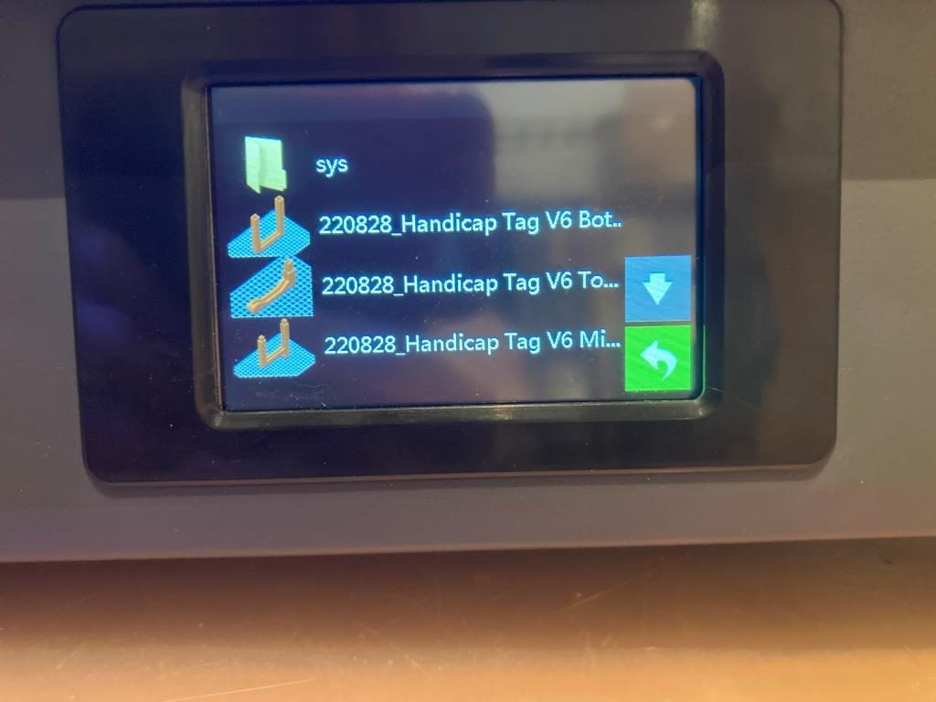
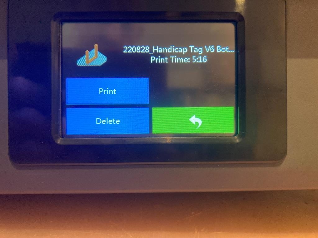
The ‘Print’ menu shows a partial list of the available print files, and allows the user to scroll up and down the list as necessary. However, as shown in the following photos, print file names are truncated after N characters, so similarly named files (I use version numbers a lot) all look the same. Moreover, when a file is actually selected by tapping on the name, it still isn’t shown full length. My Prusa MK3S+ printer has the same problem, but solves it by repeatedly scrolling through the name.

Print file list. Notice how similar they are, because the differences are later in the name
Selected print file name is also truncated – you have to just hope you have picked the correct one!

Conclusion:

The FlashForge Creator PRO 2 IDEX printer is a great printer, and I have gotten many many good prints from it over the last year. Even with the frustrations associated with the less-than-perfect GUI, I don’t regret trading down from my previous MakerGear M3-ID Independent Dual Extruder (IDEX) machine. However, I believe the GUI was not given the care and resources it needed to be a first-class example of a 3D printer user interface, and should be updated. If it remains in this ‘sort-of-OK-sort-of-clunky’ state, I think it will sour a lot of 3D makers off the FlashForge brand.

Flashforge could actually kill two birds with one stone if they were to open-source the GUI code; then users like myself who are frustrated with the current performance could collaborate in making it better.

Stay tuned,

Frank

Transitioning from TinkerCad to Blender with CAD Sketcher

Posted 6 August 2022

I have been been doing 3D printing (a ‘Maker’ in modern jargon) for almost a decade now, and almost all my designs started out life in TinkerCad – Autodesk’s wonderful online 3D design tool. As I mentioned in my 2014 post comparing AutoDesk’s TinkerCad and 123d Design offerings, TinkerCad is simple and easy to use, powerful due to its large suite of primitive 3D objects and manipulation features, but runs out of gas when dealing with rounded corners, internal fillets, arbitrary chamfers and other sophisticated mesh manipulation options.

Consequently, I have been keeping an eye out for more modern alternatives to TinkerCad – something with the horsepower to do more sophisticated mesh modeling, but still simple enough for an old broke-down engineer to learn in the finite amount of time I have left on earth. As I discovered eight years ago, AutoDesk’s 123D Design offering wasn’t the app I was looking for, but Blender, with the newly introduced CAD Sketcher and CAD Transforms add-ins, may well be. Blender seems to be aimed more at graphic artists, animators, and 3D world-builders rather than for the kind of dimension-driven precision design for 3D printing, but the CAD Sketcher and CAD Transforms add-ons go a long way toward providing explicit dimension-driven precision 3D design tools for us maker types.

I ran across the Blender app several months ago and started looking for online tutorials; the first one I found was the famous ‘Donut Tutorial’ by Blender Guru. After several tries and a large amount of frustration due to the radical GUI changes between Blender 2.x and 3.x, I was able to get most of the way through to making a donut. Unfortunately for me, the donut tutorial didn’t really address dimension-driven 3D models at all, so while the tutorial was kinda fun, it didn’t really address my issue. Then I ran across Maker Tales Jonathan Kobylanski’s demo of the CAD Sketcher V0.24 Blender add-on, and I became convinced that Blender might well be a viable TinkerCad replacment.

So, I worked my way through Jonathan’s CAD Sketcher 0.24 tutorial, and as usual got in trouble several times due to my ignorance of basic Blender GUI techniques. After posting about my problems, Jonathan was kind enough to point me at his paid “How To Use Blender For 3D Printing” 10-lesson series for $124USD. I signed right up, and so far have worked (and I do mean worked!) my way through the first six lessons. I have to say this may be the best money I’ve ever spent on self-education (and at my advanced age, that is saying a LOT 🙂 ). In particular, Jonathan starts off with the assumption that the student knows absolutely NOTHING about Blender (which was certainly true in my case) and shows how to set the program up with precision 3D modeling in mind. All lessons are extensively documented, with video, audio, and all keypresses fully described. At first I was more than a little intimidated by the deluge of short-cut keys (and still am a little bit), but Jonathan’s lessons expose the viewer to slightly more bite-size chunks than the normal fire-hose method, so I was able to stay more or less on the same continent with him as he moved through the design step. I also found it extremely helpful to go back through the first few lessons several times (very easy to do with the academy.makertales.com lesson layout), even to the point of playing and replaying particular steps until I was comfortable with whatever procedure was being taught. There is a MakerTales Discord server and a channel dedicated to helping academy students, and Jonathan seems to be pretty responsive in responding to my (usually clueless) comments and pleas for help.

Jonathan encourages his students to go beyond the lessons and to modify or extend the particular focus of any lesson, so I decided to try and use Blender/CAD Sketcher for a small project I have been considering. My main PC is a Dell XPS15 laptop, connected to two 24″ monitors via a Dell WD19TBS Thunderbolt docking station. I have the monitors on 4″ risers, but found they still weren’t high enough for comfortable viewing and seating ergonomics, so I designed (in TCAD, several years ago) a set of riser risers as shown in the image below

My two-display setup. Note the red ‘riser elevators’ under the metal display risers
Closeup showing the built-in shelf for my XPS 15 laptop

As shown above, the ‘riser elevator design incorporates a built-in shelf for my XPS15 laptop. This has worked well for years, but recently I have been looking for ways to simplify/neaten up my workspace. I found that I could move my junk tray from the side of my work area to the currently unused space underneath my laptop, but with the current arrangement there isn’t enough clearance above the tray to see/access the stuff in the back. I was originally thinking of simply replacing the current 3D printed risers with new ones 40mm higher, but in an ‘aha!’ moment I realized I didn’t have to replace the risers – I could simply add another riser on top. The new piece would mate with the current riser vertical tab that keeps the laptop from sliding sideways, and then replicate the same vertical tab, but 40mm higher.

Doing either the re-designed riser or the add-on would be trivial in TinkerCad, but I thought it would be a good project to try in Blender, now that I have some small inkling of what I’m doing there. So, after the normal number of screwups, I came up with a fully-defined sketch for a small test piece (I fully subscribe to Jonathan’s “When in doubt – test it out” philosophy), as shown:

CAD Sketcher sketch for the test piece. Same as the final piece, except for height

I then 3D printed on my Prusa MK3S printer. Halfway through the print job I realized I didn’t need the full 20mm thickness to test the geometry, so I stopped it midway through and placed it on top of one of the original risers, as shown in the following photo:

Maybe not completely perfect, but still a pretty good fit

After convincing myself that the design was going to work, I modified the sketch for the full 40mm height I wanted, and printed 4ea out, as shown:

CAD Sketcher sketch for the full-height version
4ea full-size riser add-on pieces

After installation, I now have my laptop higher by 40mm, and better/easier access to my junk tray as shown – success!

Finished project. Laptop higher by 40mm, junk tray now much more accessible

And more than that, I have now developed enough confidence in Blender/CAD Sketcher to move my 3D print designs there rather than relying strictly on TinkerCad. Thanks Jonathan!

16 August 2022 Update:

Just finished Learning Project 7: Stackable Storage Crate, and my brain is bulging at the seams – whew! After finishing, I just had to try printing one (or two, if I want to see whether or not I really got the nesting geometry right), even though each print is something over 13 hours on my Prusa MK3S with a 0.6mm nozzle. Here’s the result:

Hot off the printer – after “only” 13 hours!
Underside showing stacking groove. Printed without supports, just using bridging

Frank