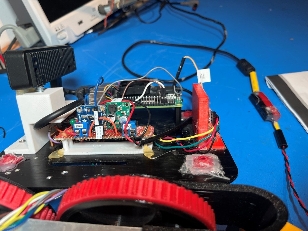
/*
Name: VL53L1X_Demo.ino
Created: 8/13/2026 8:09:07 PM
Author: FRANK_XPS_9530\Frank
*/
#include <Wire.h>
#include <VL53L1X.h>
#include "MPU6050_6Axis_MotionApps612.h" //01/18/22 changed to use the \I2CDevLib\Arduino\MPU6050\ version
VL53L1X lidar;
#pragma region PIN ASSIGNMENTS
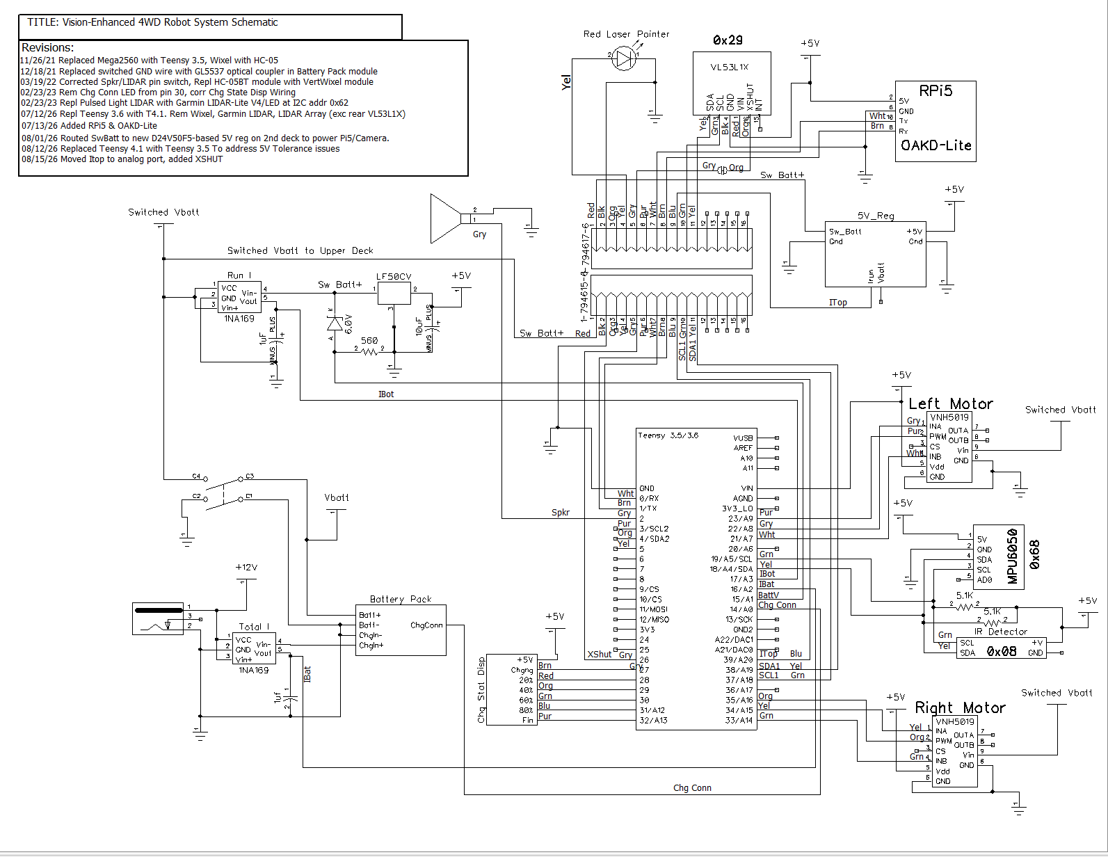
const uint8_t XSHUT_PIN = 26;
const uint8_t SW_BATT_VOLT_PIN = 15;
const uint8_t I_TOP_PIN = 39;
const uint8_t I_BOT_PIN = 17;
const uint8_t I_CHG_PIN = 16;
const uint8_t LASER_PIN = 5;
const uint8_t SPEAKER_PIN = 2;
#pragma endregion PIN ASSIGNMENTS
#pragma region ADC CONSTANTS
const float ADC_REF_VOLTS = 3.3; //teensy default for analog inputs
const int MAX_AD_COUNT = 1023;
const float AmpsPerVolt = 1.00; //default 10K Rs
const float VoltsPerCount = ADC_REF_VOLTS / MAX_AD_COUNT;
const float VOLTAGE_TO_CURRENT_RATIO = 1.f; //Used for both 'Total' and 'Run' sensors
#pragma endregion ADC CONSTANTS
const float ZENER_VOLTAGE_OFFSET = 5.96; //03/14/22 measured zener voltage
const char* WallFollowTelemStr = "%2.1f\t%2.1f\t%2.1f\t%2.1f\t%2.1f\t%2.1f\t%2.2f\t%2.2f\t%2.0f\t%2.1f\t%d\t%d\t%s\t%s\n";//05/12/23 added L/R motor speeds
const char* ColumnHeaderStr = "Msec\tBattV\tTop_I\tBot_I\tChg_I\tRear_mm\tHdgDeg\n";
//11/07/2020 moved all I2C Address declarations here
#pragma region I2C_ADDRESSES
#define IRDET_I2C_ADDR 0x08
#define MPU6050_I2C_ADDR 0x68
#pragma endregion I2C_ADDRESSES
#pragma region MPU6050_SUPPORT
uint8_t mpuIntStatus; // holds actual interrupt status byte from MPU. Used in Homer's Overflow routine
uint8_t devStatus; // return status after each device operation (0 = success, !0 = error)
uint16_t packetSize; // expected DMP packet size (default is 42 bytes)
uint16_t fifoCount; // count of all bytes currently in FIFO
uint8_t fifoBuffer[64]; // FIFO storage buffer
// orientation/motion vars
Quaternion q; // [w, x, y, z] quaternion container
VectorInt16 aa; // [x, y, z] accel sensor measurements
VectorInt16 aaReal; // [x, y, z] gravity-free accel sensor measurements
VectorInt16 aaWorld; // [x, y, z] world-frame accel sensor measurements
VectorFloat gravity; // [x, y, z] gravity vector
float euler[3]; // [psi, theta, phi] Euler angle container
float ypr[3]; // [yaw, pitch, roll] yaw/pitch/roll container and gravity vector
int GetPacketLoopCount = 0;
int OuterGetPacketLoopCount = 0;
//MPU6050 status flags
bool bMPU6050Ready = true;
bool dmpReady = false; // set true if DMP init was successful
volatile float IMUHdgValDeg = 0; //updated by UpdateIMUHdgValDeg()//11/02/20 now updated in ISR
const uint16_t MAX_GETPACKET_LOOPS = 100; //10/30/19 added for backup loop exit condition in GetCurrentFIFOPacket()
uint8_t GetCurrentFIFOPacket(uint8_t* data, uint8_t length, uint16_t max_loops = MAX_GETPACKET_LOOPS); //prototype here so can define a default param
bool bFirstTime = true;
//#define MPU6050_CCW_INCREASES_YAWVAL //added 12/05/19 commented out 11/22/21 as now the MPU6050 module is mounted 'Z-up'
#pragma endregion MPU6050 Support
#pragma region HEADING_AND_RATE_BASED_TURN_PARAMETERS
float Prev_HdgDeg = 0; //02/01/23 - this should be a local variable in SpinTurn()
float TurnRatePIDOutput; //02/01/23 - this should be a local variable in SpinTurn()
//06/04/22 from WallE3_SpinTurnTuning.ino
float TurnRate_Kp = 0.7;//02/03/23 updated Kp from 1.0 to 0.7 per https://www.fpaynter.com/2022/12/walle3-spin-turn-revisited/
float TurnRate_Ki = 0.3;
float TurnRate_Kd = 0.0;//02/03/23 updated Kd from 0.1 to 0.0 per https://www.fpaynter.com/2022/12/walle3-spin-turn-revisited/
//ported from FourWD_PulseTurnRateTest.ino
const float HDG_NEAR_MATCH_VAL = 0.8; //slow the turn down here
const float HDG_FULL_MATCH_VAL = 0.99; //stop the turn here //rev 06/01/21
const float HDG_MIN_MATCH_VAL = 0.6; //added 09/08/18: don't start checking slope until turn is well started
const float DEFAULT_TURN_RATE_DEGPERSEC = 45.f; //06/06/21 updated
const uint16_t HEADING_HISTORY_ARRAY_SIZE = 50; //06/12/23 added for 'spinning' condx detection
float gl_HdgHistoryArray[HEADING_HISTORY_ARRAY_SIZE];
//02/16/22 fwd decl reqd for fcns using default param
//09/16/23 added RunBothMotorsMsec with default params
//bool SpinTurn(bool b_ccw, float numDeg, float degPersec = DEFAULT_TURN_RATE_DEGPERSEC);
//
////06/01/24 chg int gl_Leftspeednum to uint16_t leftspeednum, int gl_Rightspeednum to uint16_t rightspeednum
////void RunBothMotorsMsec(bool bisFwd, int timeMsec = 500, int gl_Leftspeednum = MOTOR_SPEED_HALF, int gl_Rightspeednum = MOTOR_SPEED_HALF);
//void RunBothMotorsMsec(bool bisFwd, int timeMsec = 500, uint16_t leftspeednum = MOTOR_SPEED_HALF, uint16_t rightspeednum = MOTOR_SPEED_HALF);
//bool RollingTurn(bool b_ccw, bool b_fwd, float numDeg, float Kp, float Ki, float Kd, float degPersec = DEFAULT_TURN_RATE_DEGPERSEC);
//bool IsChargerConnected(bool curState = false);
#pragma endregion HEADING_AND_RATE_BASED_TURN_PARAMETERS
MPU6050 mpu(MPU6050_I2C_ADDR);
void setup()
{
Serial.begin(115200);
while (!Serial && millis() < 3000);
delay(500);
// Reset the sensor
pinMode(XSHUT_PIN, OUTPUT);
digitalWrite(XSHUT_PIN, LOW);
delay(10);
digitalWrite(XSHUT_PIN, HIGH);
delay(20);
Wire.begin();
Wire.setClock(400000);
// Use Wire1 instead of Wire for rear LIDAR
Wire1.begin();
Wire1.setClock(400000);
lidar.setBus(&Wire1); // <-- this is the key line
lidar.setTimeout(500);
if (!lidar.init())
{
Serial.println("Failed to detect and initialize VL53L1X on Wire1!");
while (1);
}
Serial.println("VL53L1X detected on Wire1 and initialized");
lidar.setDistanceMode(VL53L1X::Long);
lidar.setMeasurementTimingBudget(50000);
lidar.startContinuous(50);
//init current sensor pins
pinMode(I_BOT_PIN, INPUT);
pinMode(I_TOP_PIN, INPUT);
pinMode(I_CHG_PIN, INPUT);
pinMode(LASER_PIN, OUTPUT);
//exercise the laser diode
digitalWrite(LASER_PIN, HIGH);
delay(200);
digitalWrite(LASER_PIN, LOW);
delay(200);
digitalWrite(LASER_PIN, HIGH);
delay(200);
digitalWrite(LASER_PIN, LOW);
//Exercise the speaker
tone(SPEAKER_PIN, 1000, 2000); //returns immediately
#pragma region MPU6050
#ifndef NO_MPU6050
Serial.printf("\nChecking for MPU6050 IMU at I2C Addr 0x%x\n", MPU6050_I2C_ADDR);
Serial.println(mpu.testConnection() ? F("MPU6050 connection successful") : F("MPU6050 connection failed"));
mpu.initialize();
// verify connection
float StartSec = 0; //used to time MPU6050 init
Serial.println(F("Initializing DMP..."));
devStatus = mpu.dmpInitialize();
// make sure it worked (returns 0 if successful)
if (devStatus == 0)
{
// turn on the DMP, now that it's ready
Serial.printf(F("Enabling DMP...\n"));
mpu.setDMPEnabled(true);
// set our DMP Ready flag so the main loop() function knows it's okay to use it
Serial.println(F("DMP ready! Waiting for MPU6050 drift rate to settle..."));
dmpReady = true;
// get expected DMP packet size for later comparison
packetSize = mpu.dmpGetFIFOPacketSize();
Serial.printf(F("Calibrating...Retrieving Calibration Values\n\n"));
mpu.CalibrateGyro(); //using default value of 15
mpu.PrintActiveOffsets();
//loop heading display until stabilized
Serial.printf(F("\nMsec\tHdg\n"));
UpdateIMUHdgValDeg();
Prev_HdgDeg = IMUHdgValDeg;
delay(100);
UpdateIMUHdgValDeg();
Serial.printf("%lu\t%2.3f\t%2.3f\n", millis(), IMUHdgValDeg, Prev_HdgDeg);
while (abs(IMUHdgValDeg - Prev_HdgDeg) > 0.1f)
{
Serial.printf("%lu\t%2.3f\n", millis(), IMUHdgValDeg);
Prev_HdgDeg = IMUHdgValDeg;
delay(100);
UpdateIMUHdgValDeg();
}
StartSec = millis() / 1000.f;
Serial.printf("MPU6050 Ready at %2.2f Sec with delta = %2.3f\n", StartSec, IMUHdgValDeg - Prev_HdgDeg);
bMPU6050Ready = true;
delay(1000);
}
else //MPU6050 Init failed for some reason
{
// ERROR!
// 1 = initial memory load failed
// 2 = DMP configuration updates failed
// (if it's going to break, usually the code will be 1)
Serial.printf("DMP Initialization failed with code %d", devStatus);
//08/29/21 print out battery voltage on failure
//float batV = GetBattVoltage();
//gl_batteryVoltage = GetBattVoltage();
//Serial.printf("Battery Voltage = %2.2f\n", gl_batteryVoltage);
bMPU6050Ready = false;
}
#endif // !NO_MPU6050
#pragma endregion MPU6050
//Serial.printf("Msec\tBattV\tTop_I\tBot_I\tChg_I\tRear_mm\n");
Serial.printf(ColumnHeaderStr);
}
void loop()
{
//rear-facing VL53L1X
uint16_t rear_mm = lidar.read();
//Serial.print(rear_mm);
if (lidar.timeoutOccurred())
{
Serial.print(" TIMEOUT");
}
//04/02/21 moved to 'fast' part of loop
float BattV = GetVoltage(SW_BATT_VOLT_PIN);
float TopI = GetAmps(I_TOP_PIN);
float BotI = GetAmps(I_BOT_PIN);
float ChgI = GetAmps(I_CHG_PIN);
UpdateIMUHdgValDeg(); //updatees IMUHdgValDeg
//Serial.printf("\Msec\tBattV\tTop_I\tBot_I\tChg_I\tRear_mm\n");
Serial.printf("%lu\t%2.2f\t%2.2f\t%2.2f\t%2.2f\t%d\t%2.2f\n", millis(), BattV, TopI, BotI, ChgI, rear_mm, IMUHdgValDeg );
delay(100);
}
float GetAmps(int pin_number)
{
//Purpose: Get current in amps
//Inputs:
// pin_number = integer denoting analog pin to be used for measurement
// VOLTAGE_TO_CURRENT_RATIO = measured voltage to current ratio
// MAX_AD_COUNT = int denoting max A/D reading value
// VOLTAGE_TO_CURRENT_RATIO = int denoting conversion ratio
//Outputs:
// returns total robot current (chg current plus running current)
//Notes:
// 02/28/18 chg name from GetBattChgAmps() to GetTotalAmps()
// 11/24/21 chg name, add pin_number param so can use for both Itot & Irun
int reading = analogRead(pin_number); //range is 0-1023
float volts = ((float)reading / (float)MAX_AD_COUNT) * ADC_REF_VOLTS;
float amps = volts * VOLTAGE_TO_CURRENT_RATIO;
//DEBUG!!
//Serial.printf("GetAmps(%d): reading, volts, amps = %d, %3.2f, %3.2f\n",
// pin_number, reading, volts, amps);
//DEBUG!!
return amps;
}
float GetVoltage(uint8_t volt_pin)
{
//02/18/17 get corrected battery voltage. Voltage reading is 1/3 actual Vbatt value
int analog_batt_reading = analogRead(volt_pin);//analogReadAveraging(8) in setup() does internal averaging
float calc_volts = ZENER_VOLTAGE_OFFSET + ADC_REF_VOLTS * (float)analog_batt_reading / (float)MAX_AD_COUNT;
//DEBUG!!
//for(int i = 0; i < 8;i++)
//{
// int analog_batt_reading = analogRead(BATT_MON_PIN);//analogReadAveraging(8) in setup() does internal averaging
// float calc_volts = ZENER_VOLTAGE_OFFSET + ADC_REF_VOLTS * (float)analog_batt_reading / (float)MAX_AD_COUNT;
// gl_pSerPort->printf("a/d = %d, calc = %2.2f\n", analog_batt_reading,calc_volts);
// delay(100);
//}
//DEBUG!!
return calc_volts;
}
float UpdateIMUHdgValDeg()
{
//Purpose: Get latest yaw (heading) value from IMU
//Inputs: None. This function should only be called after mpu.dmpPacketAvailable() returns TRUE
//Outputs:
// returns true if successful, otherwise false
// IMUHdgValDeg updated on success
//Plan:
//Step1: check for overflow and reset the FIFO if it occurs. In this case, wait for new packet
//Step2: read all available packets to get to latest data
//Step3: update IMUHdgValDeg with latest value
//Notes:
// 10/08/19 changed return type to boolean
// 10/08/19 no longer need mpuIntStatus
// 10/21/19 completely rewritten to use Homer's algorithm
// 05/05/20 changed return type to float vs bool.
// 06/13/23 added code to update gl_HdgHistoryArray for 'spinning' condx detection
int flag = GetCurrentFIFOPacket(fifoBuffer, packetSize, MAX_GETPACKET_LOOPS); //get the latest mpu packet
if (flag != 0) //0 = error exit, 1 = normal exit, 2 = recovered from an overflow
{
// display Euler angles in degrees
mpu.dmpGetQuaternion(&q, fifoBuffer);
mpu.dmpGetGravity(&gravity, &q);
mpu.dmpGetYawPitchRoll(ypr, &q, &gravity);
//compute the yaw value
IMUHdgValDeg = ypr[0] * 180 / M_PI;
}
//06/13/23 added to update gl_HdgHistoryArray for 'spinning' condx detection
//all array entries bumped down one, with most recent value at i = HEADING_HISTORY_ARRAY_SIZE-1
for (uint16_t i = 1; i < HEADING_HISTORY_ARRAY_SIZE; i++)
{
gl_HdgHistoryArray[i - 1] = gl_HdgHistoryArray[i];
//gl_pSerPort->printf("gl_HdgHistoryArray[%d] = %2.2f\n", i, gl_HdgHistoryArray[i]);
}
gl_HdgHistoryArray[HEADING_HISTORY_ARRAY_SIZE - 1] = IMUHdgValDeg;
return IMUHdgValDeg;//05/05/20 now returns updated value for use convenience
}
uint8_t GetCurrentFIFOPacket(uint8_t* data, uint8_t length, uint16_t max_loops)
{
mpu.resetFIFO();
delay(1);
//int countloop = 0;
fifoCount = mpu.getFIFOCount();
GetPacketLoopCount = 0;
//gl_pSerPort->printf("In GetCurrentFIFOPacket: before loop fifoC = %d\t", fifoCount);
while (fifoCount < packetSize && GetPacketLoopCount < max_loops)
{
GetPacketLoopCount++;
fifoCount = mpu.getFIFOCount();
delay(2);
}
//gl_pSerPort->printf("In GetCurrentFIFOPacket: after loop fifoC = %d, loop count = %d\n", fifoCount, GetPacketLoopCount);
if (GetPacketLoopCount >= max_loops)
{
return 0;
}
//if we get to here, there should be exactly one packet in the FIFO
mpu.getFIFOBytes(data, packetSize);
return 1;
}