Posted 03 August 2026,
Part 1 in this series laid out the strategy for adding vision processing capabilities to my 4-wheel robot. This post continues that effort.
The first step was to replace the Teensy 3.6 main controller with a Teensy 4.1. As part of this process, I also replaced the glued-on ‘Gnd’ and ‘+5V’ bussbars with a bit more finished product, as you can see in the following photos:
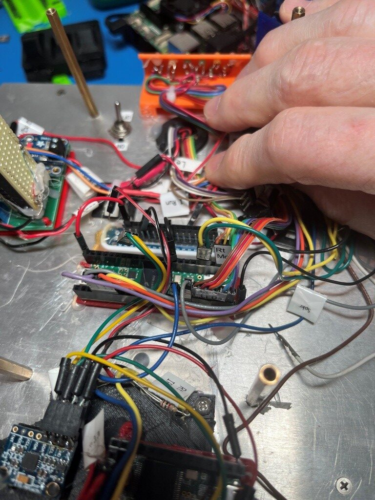
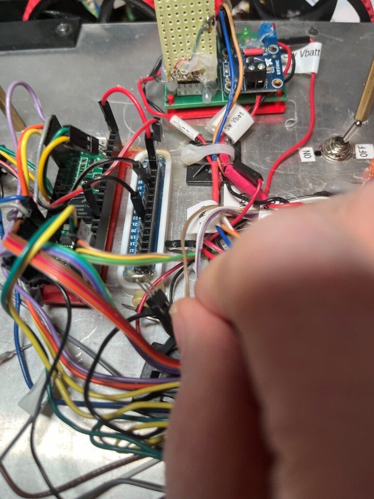
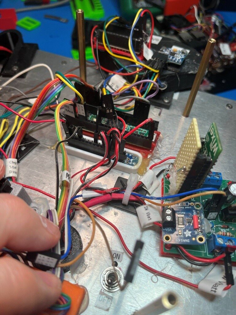
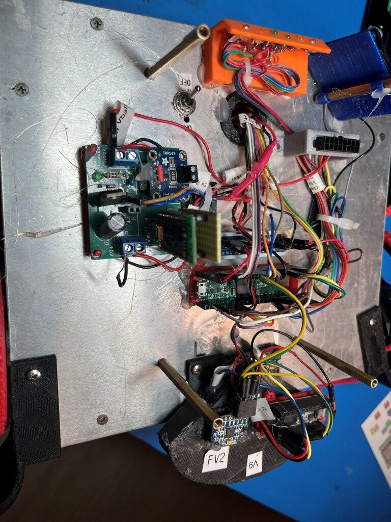
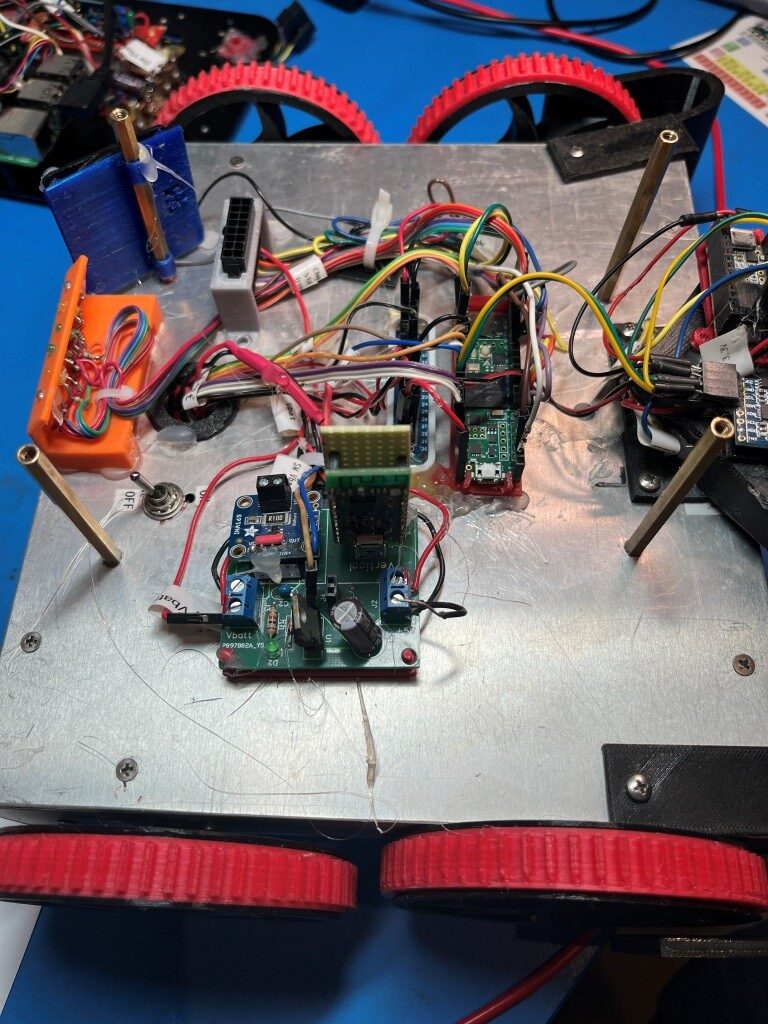
The next step is moving the old 4-wheel firmware to the ‘new-improved’ 4-wheel hardware. I started this by porting “C:\Users\Frank\Documents\Arduino\WallE3_Git\WallE3_Git\WallE3_Git.ino” to “C:\Users\Frank\Documents\Robot_Projects\VisionEnhaned4WheelRobot_V1\VisionEnhaned4WheelRobot_V1.ino”. This took a while, and I’m not sure I wouldn’t have been better off just cloning the entire WallE3_Git.ino file, but I “got it done’.
05 August 2026 Update:
It took a while, but I now have a working 4-wheel drive robot program running again on the 4-wheel chassis with a Teensy 4.1 main controller The only small ‘gotcha’ I encountered during the Teensy 3.5 -> Teensy 4.1 controller switch was the control lines for the right motor driver. It turns out the ‘speed’ (PWM) pin used on the Teensy 3.5 isn’t PWM-capable on the Teensy 4.1, so this required some minor pin swapping, as shown below:
|
1 2 3 4 5 6 7 8 9 |
//08/05/26 pin 35 isn't PWMable on Teensy 4.1, but pin 33 is //const uint16_t InA_Right = 34; //const uint16_t InB_Right = 33; //const uint16_t Spd_Right = 35; //Teensy 4.1 const uint16_t InA_Right = 34; const uint16_t InB_Right = 35; const uint16_t Spd_Right = 33; |
Using the manual control features built accessible via the ‘CheckforUserInput() function, I was able to perform left/right 10 degree turns and speed up/slow down, all from my keyboard. I don’t have the second deck connected up yet, but that is next on the agenda.
06 August 2026 Update:
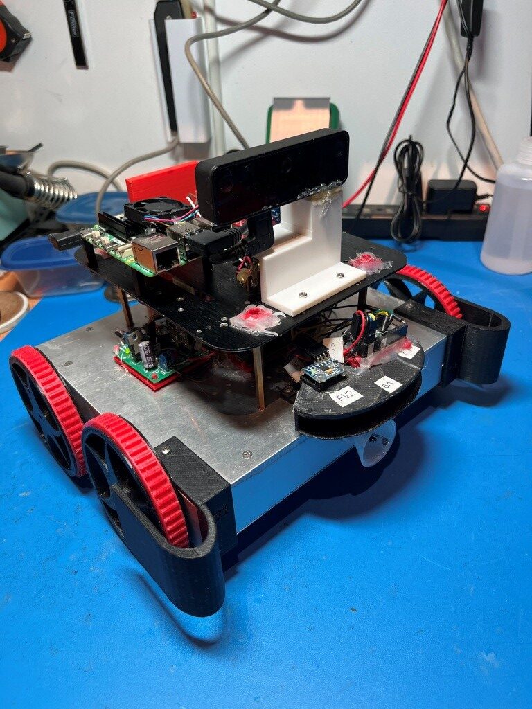
At this point I have a complete 4-wheel drive robot assembled with a Raspberry Pi5 and OAKD-Lite camera, and I can send it basic (left/right/faster/slower/forward/reverse) movement commands via a serial port. In previous work on the 2-wheel robot I demonstrated the ability to send vision-processing-derived movement commands to the main processor from the Pi5 via a serial port.
It occurs to me that with the above capability, The robot doesn’t really need anything else for navigation and obstacle avoidance. The OAKD-Lite can provide visual depth information to the Pi5, and the Pi5 can send basic movement commands to the robot. In addition, it seems to me that I might be able to eliminate the entire ‘homing-to-charger’ software and hardware blocks, as the camera should be able to tell the Pi5 where the charger dock is located in the field of view, and the Pi5 should be able to tell the robot which way to turn and by how much, and when to speed up and slow down. This could make the robot a LOT simpler (as Elon Musk said about Tesla FSD “Once you have vision solved, you no longer need anything else’).
08 August 2026 Update:
The robot is alive! With Grok’s help I now have a python script running on the Pi5 that can direct the robot to turn left or right depending on image processing by the OAKD-Lite camera.
First, the Python shell script ‘restart_camera.sh’ is executed to get the OAKD-Lite camera ready:
|
1 2 3 4 5 6 7 8 9 10 11 12 13 14 15 16 17 |
pi@RobotPi5:~$ cd my_vision_robot/ pi@RobotPi5:~/my_vision_robot$ ./software/scripts/restart_camera.sh === Killing old camera processes === === Sourcing environments === === Starting camera === [INFO] [launch]: All log files can be found below /home/pi/.ros/log/2026-08-08-08-25-25-554555-RobotPi5-3196 [INFO] [launch]: Default logging verbosity is set to INFO [INFO] [camera_node-1]: process started with pid [3200] [camera_node-1] [INFO] [1786191927.851165044] [camera]: Starting camera. [camera_node-1] [INFO] [1786191927.875363720] [camera]: No ip/mxid specified, connecting to the next available device. [camera_node-1] [INFO] [1786191930.182731755] [camera]: Camera with MXID: 19443010B166F01200 and Name: 4.1 connected! [camera_node-1] [INFO] [1786191930.184436975] [camera]: USB SPEED: SUPER [camera_node-1] [INFO] [1786191930.211320937] [camera]: Device type: OAK-D-LITE [camera_node-1] [INFO] [1786191930.213305230] [camera]: Pipeline type: Depth [camera_node-1] [ERROR] [1786191930.379447850] [camera]: rgb parameters not set, defaulting to 1280x720 unless specified otherwise. [camera_node-1] [INFO] [1786191930.380454015] [camera]: Finished setting up pipeline. [camera_node-1] [INFO] [1786191930.680038467] [camera]: Camera ready! |
Once the camera is ready, then the demo program ‘clearest_direction_node.py’ is executed on the Pi5 (with ‘VisionEnhanced4WheelRobot.ino already running on the Teensy 4.1)
Based on a rudimentary analysis of the depth (distance) distribution in the camera field of view, the ‘clearest_direction_node.py’ Python script sends left/right/stop commands to the Teensy 4.1 from the Pi5’s serial port to the Teensy 4.1’s ‘Serial1’ port. The commands use the already-existing robot manual motion control command structure shown below:
|
1 2 3 4 5 6 7 8 9 10 11 12 13 |
ENTERING COMMAND MODE: 0 = 180 deg CCW Turn 1 = 180 deg CW Turn A = Abort - Reboots Processor / = Forward .(dot) = Reverse * = Exit ChkForUserInput() Faster 8 Left 4 5 6 Right 2 Slower |
|
1 2 3 4 5 6 7 8 9 10 11 12 13 14 |
pi@RobotPi5:~/my_vision_robot$ python3 software/scripts/clearest_direction_node.py --ros-args -p enable_motion:=True [INFO] [1786192457.618821619] [clearest_direction_node]: Motion ENABLED – opened /dev/ttyAMA0 @ 115200 and sent "C" (command mode) [INFO] [1786192457.672358648] [clearest_direction_node]: Clearest Direction Node started (7 sectors, bottom half only) [INFO] [1786192457.689451373] [clearest_direction_node]: Sent "6" → right 10° (recommended 31°) [INFO] [1786192467.311608370] [clearest_direction_node]: Sent "5" → stop (turn 0° inside deadband ±6.0°) [INFO] [1786192468.114612060] [clearest_direction_node]: Sent "6" → right 10° (recommended 31°) [INFO] [1786192478.041447563] [clearest_direction_node]: Sent "4" → left 10° (recommended -10°) [INFO] [1786192478.846585878] [clearest_direction_node]: Sent "6" → right 10° (recommended 31°) [INFO] [1786192481.741594815] [clearest_direction_node]: Sent "5" → stop (turn 0° inside deadband ±6.0°) [INFO] [1786192482.545474512] [clearest_direction_node]: Sent "6" → right 10° (recommended 31°) [INFO] [1786192490.073479144] [clearest_direction_node]: Sent "4" → left 10° (recommended -31°) [INFO] [1786192490.877634051] [clearest_direction_node]: Sent "6" → right 10° (recommended 31°) [INFO] [1786192493.239450490] [clearest_direction_node]: Sent "5" → stop (turn 0° inside deadband ±6.0°) [INFO] [1786192494.044599603] [clearest_direction_node]: Sent "6" → right 10° (recommended 31°) |
Here’s a short video showing the action
Here’s another short video showing the robot actually making 10-deg turns left & right in response to a simulated obstacle in the field of view:
And here is some of the telemetry output from the above run:
|
1 2 3 4 5 6 7 8 9 10 11 12 13 14 15 16 17 18 19 20 21 22 23 24 25 26 27 28 29 30 31 32 33 34 35 36 37 38 39 40 41 42 43 44 |
m) [INFO] [1786294925.766194888] [clearest_direction_node]: Sent "5" → stop (best depth 0 mm < 400 mm) [INFO] [1786294926.567160145] [clearest_direction_node]: Sent "6" → right 10° (recommended 21°) [INFO] [1786294928.101189495] [clearest_direction_node]: Sent "5" → stop (turn 0° inside deadband ±6.0°) [INFO] [1786294928.901243868] [clearest_direction_node]: Sent "5" → stop (turn 0° inside deadband ±6.0°) [INFO] [1786294929.701313191] [clearest_direction_node]: Sent "6" → right 10° (recommended 21°) [INFO] [1786294930.601312174] [clearest_direction_node]: Sent "5" → stop (turn 0° inside deadband ±6.0°) [INFO] [1786294931.434187553] [clearest_direction_node]: Sent "5" → stop (best depth 0 mm < 400 mm) [INFO] [1786294932.266154731] [clearest_direction_node]: Sent "5" → stop (turn 0° inside deadband ±6.0°) [INFO] [1786294933.067315737] [clearest_direction_node]: Sent "5" → stop (best depth 0 mm < 400 mm) [INFO] [1786294933.900181102] [clearest_direction_node]: Sent "5" → stop (best depth 0 mm < 400 mm) [INFO] [1786294934.700201135] [clearest_direction_node]: Sent "6" → right 10° (recommended 10°) [INFO] [1786294936.067153241] [clearest_direction_node]: Sent "5" → stop (turn 0° inside deadband ±6.0°) [INFO] [1786294936.900076933] [clearest_direction_node]: Sent "6" → right 10° (recommended 21°) [INFO] [1786294939.201264474] [clearest_direction_node]: Sent "4" → left 10° (recommended -10°) [INFO] [1786294940.067229716] [clearest_direction_node]: Sent "6" → right 10° (recommended 21°) [INFO] [1786294941.068341556] [clearest_direction_node]: Sent "5" → stop (turn 0° inside deadband ±6.0°) [INFO] [1786294941.901316245] [clearest_direction_node]: Sent "6" → right 10° (recommended 10°) [INFO] [1786294943.168337641] [clearest_direction_node]: Sent "5" → stop (turn 0° inside deadband ±6.0°) [INFO] [1786294944.001189364] [clearest_direction_node]: Sent "6" → right 10° (recommended 31°) [INFO] [1786294944.866160026] [clearest_direction_node]: Sent "4" → left 10° (recommended -10°) [INFO] [1786294945.798186488] [clearest_direction_node]: Sent "6" → right 10° (recommended 31°) [INFO] [1786294946.600316490] [clearest_direction_node]: Sent "4" → left 10° (recommended -21°) [INFO] [1786294947.600156058] [clearest_direction_node]: Sent "6" → right 10° (recommended 10°) [INFO] [1786294949.299158322] [clearest_direction_node]: Sent "5" → stop (turn 0° inside deadband ±6.0°) [INFO] [1786294950.100182709] [clearest_direction_node]: Sent "6" → right 10° (recommended 31°) [INFO] [1786294951.433310857] [clearest_direction_node]: Sent "4" → left 10° (recommended -21°) [INFO] [1786294952.265305195] [clearest_direction_node]: Sent "6" → right 10° (recommended 31°) [INFO] [1786294953.832184082] [clearest_direction_node]: Sent "4" → left 10° (recommended -10°) [INFO] [1786294954.664313739] [clearest_direction_node]: Sent "6" → right 10° (recommended 31°) [INFO] [1786294956.765188420] [clearest_direction_node]: Sent "5" → stop (turn 0° inside deadband ±6.0°) [INFO] [1786294957.597195768] [clearest_direction_node]: Sent "4" → left 10° (recommended -31°) [INFO] [1786294958.429191481] [clearest_direction_node]: Sent "5" → stop (best depth 0 mm < 400 mm) [INFO] [1786294959.230315045] [clearest_direction_node]: Sent "5" → stop (best depth 0 mm < 400 mm) [INFO] [1786294960.031185898] [clearest_direction_node]: Sent "6" → right 10° (recommended 31°) [INFO] [1786294960.998157709] [clearest_direction_node]: Sent "5" → stop (turn 0° inside deadband ±6.0°) [INFO] [1786294961.831224208] [clearest_direction_node]: Sent "6" → right 10° (recommended 21°) [INFO] [1786294964.598186768] [clearest_direction_node]: Sent "4" → left 10° (recommended -10°) [INFO] [1786294965.431191999] [clearest_direction_node]: Sent "6" → right 10° (recommended 21°) [INFO] [1786294971.431270013] [clearest_direction_node]: Sent "4" → left 10° (recommended -10°) [INFO] [1786294972.264315801] [clearest_direction_node]: Sent "6" → right 10° (recommended 21°) [INFO] [1786294974.930187367] [clearest_direction_node]: Sent "4" → left 10° (recommended -21°) [INFO] [1786294975.731189452] [clearest_direction_node]: Sent "6" → right 10° (recommended 21°) [INFO] [1786294978.798182012] [clearest_direction_node]: Sent "4" → left 10° (recommended -31°) |
At this point in the project, we have demonstrated that visual ‘depth’ information can be used to guide the robot, and we have separately demonstrated that the Teensy firmware can be updated ‘Over The Air’ (OTA) via the wifi connection to the Pi5. I believe the next step should be to add wifi OTA to the ‘clearest_direction_node.py’ script in order to remove the requirement for physically attaching a USB cable to the Teensy 4.1 to update the firmware.
08 August 2026 Update:
Adding Wifi OTA to the current ‘clearest_direction_node.py’ configuration turned out to be relatively easy, as this ability had already been developed as a stand-alone demo back in June 2026. All we had to do was update the ‘board.txt’ file to point to the new location of ‘PostBuild_OTA.py’ on my PC, and make sure ‘Wifi_OTA.py’ was running on the Pi5 so it would look for changes in “/home/pi/my_vision_robot/firmware/latest.hex” and trigger the update.
09 August 2026 Update:
Thinking while drifting off to sleep last night, I realized that the addition of the Pi5 to the robot means that all the navigation and obstacle avoidance tasks (including possibly navigating to and connecting with the charger module) will be handled by the Pi5, which significantly simplifies the Teensy 4.1 code. All the Teensy code has to do now is respond to motion commands from the Pi5, monitor the various hardware sensors and update the rear-facing LED array.
Teensy Responsibilities:
- Run the motors in response to motion commands from Pi5 on Serial1
- Update the ‘state-of-charge’ (and left/right steering) LEDs
- Monitor the output from three different 1NA169 current sensors (I_chg, I_tot, I_upper-deck)
- Monitor the output from two different Vbatt voltage sensors (V_batt, V_upper-deck)
- Monitor the ‘charger connected’ output from the TPS5100 battery pack
- Monitor the rear-facing VL53L1X LIDAR for rear collision avoidance
- Run the speaker
- Home in on and connect to the charger module (may be done by the Pi5 instead)
Pi5 Responsibilities:
- Manage all navigation and obstacle avoidance tasks
- Possibly manage charger module homing (April tag?)
- Create map (SLAM)?
- Respond to rear-facing obstacle alerts from Teensy
- Pass robot telemetry data on Serial1 to PC
- Pass Pi5-software-related telemetry data to VS Code terminal
10 August 2026 Update:
Good progress on the vision-enhanced robot project today. Yesterday we installed two additional cases in the switch block that accepts manual control commands for the robot, to allow the user to command left/right turns of an arbitrary number of degrees at an arbitrary turn rate. The command format consists of the letter ‘L’ (left/CCW) or ‘R’ (Right/CW) followed by the number of degrees to turn (and optionally a specified turn rate in deg/sec), but the commands failed. Today (while waiting in the cellphone lot for my wife) I figured out what was wrong with the teensy command parsing code. Now I can type “L30.5” at a VS Code prompt that gets transmitted via SSH over Wifi to the Pi5, then via the dedicated serial to the Teensy. Then the Teensy calls ‘SpinTurn(30.5, rate = 30) to actually effect the turn. Here’s a short video showing a left (CCW) turn of approximately 90 deg at a 90 deg/sec rate, followed by another left turn of 90 deg at the default 30 deg/sec rate, followed by a right turn of 180 deg at the default 30 deg/sec rate:
We also implemented a replacement for my old telemetry display using the Visual Studio serial port monitor. In theory I could maintain that feature as I still have the HC-05 Bluetooth serial module installed on the robot, but I would rather put everything over wifi for better range & reliability. What we did instead was to have WallE_5.py log everything that comes to it on its serial port (Teeny ‘Serial1’) to a ‘telemetry.log’ file, which allows me to start up a new Pi5 terminal session in its own window and run
|
1 |
tail -f ~/my_vision_robot/logs/telemetry.log |
to display whatever telemetry information the teensy is sending to ‘Serial1’. Here’s a short sampling of the telemetry data setup:
|
1 2 3 4 5 6 7 8 9 10 11 12 13 14 15 16 17 18 19 20 21 22 23 24 25 26 27 28 29 30 31 32 33 34 35 36 37 38 39 40 41 42 43 44 45 46 47 48 49 50 51 52 53 54 55 56 57 58 59 60 61 62 63 64 65 66 67 68 69 70 71 72 73 74 |
pi@RobotPi5:~/my_vision_robot$ tail -f logs/telemetry.log In Default Case: Stopping Motors! I received L30 In R/L Case with incomingByte = L In R/L Case with b_ccw = CW numBuf = 30 CCW 30.00 deg @ 45.0 deg/s In SpinTurn(CCW, 30.00, 45.00) with PID = (0.7,0.3,0.0) I received C In Default Case: Stopping Motors! I received L30.5,10 In R/L Case with incomingByte = L In R/L Case with b_ccw = CW numBuf = 30.5, CCW 30.50 deg @ 45.0 deg/s In SpinTurn(CCW, 30.50, 45.00) with PID = (0.7,0.3,0.0) I received L30 In R/L Case with incomingByte = L In R/L Case with b_ccw = CW numBuf = 30 CCW 30.00 deg @ 45.0 deg/s In SpinTurn(CCW, 30.00, 45.00) with PID = (0.7,0.3,0.0) In R/L Case with incomingByte = L In R/L Case with b_ccw = CW numBuf = 30,45 CCW 30.00 deg @ 45.0 deg/s In SpinTurn(CCW, 30.00, 45.00) with PID = (0.7,0.3,0.0) In R/L Case with incomingByte = R In R/L Case with b_ccw = CCW numBuf = 30,60 CW 30.00 deg @ 60.0 deg/s In SpinTurn(CW, 30.00, 60.00) with PID = (0.7,0.3,0.0) I received R60,60 In R/L Case with incomingByte = R In R/L Case with b_ccw = CCW numBuf = 60,60 CW 60.00 deg @ 60.0 deg/s In SpinTurn(CW, 60.00, 60.00) with PID = (0.7,0.3,0.0) In R/L Case with incomingByte = R In R/L Case with b_ccw = CCW numBuf = 60 CW 60.00 deg @ 45.0 deg/s In SpinTurn(CW, 60.00, 45.00) with PID = (0.7,0.3,0.0) In R/L Case with incomingByte = R In R/L Case with b_ccw = CCW numBuf = 30 CW 30.00 deg @ 45.0 deg/s In SpinTurn(CW, 30.00, 45.00) with PID = (0.7,0.3,0.0) I received L90 In R/L Case with incomingByte = L In R/L Case with b_ccw = CW numBuf = 90 CCW 90.00 deg @ 45.0 deg/s In SpinTurn(CCW, 90.00, 45.00) with PID = (0.7,0.3,0.0) In R/L Case with incomingByte = R In R/L Case with b_ccw = CCW numBuf = 10 CW 10.00 deg @ 45.0 deg/s In SpinTurn(CW, 10.00, 45.00) with PID = (0.7,0.3,0.0) In R/L Case with incomingByte = R In R/L Case with b_ccw = CCW numBuf = 90,90 CW 90.00 deg @ 90.0 deg/s In SpinTurn(CW, 90.00, 90.00) with PID = (0.7,0.3,0.0) In R/L Case with incomingByte = L In R/L Case with b_ccw = CW numBuf = 90,90 CCW 90.00 deg @ 90.0 deg/s In SpinTurn(CCW, 90.00, 90.00) with PID = (0.7,0.3,0.0) In R/L Case with incomingByte = R In R/L Case with b_ccw = CCW numBuf = 90 CW 90.00 deg @ 45.0 deg/s In SpinTurn(CW, 90.00, 45.00) with PID = (0.7,0.3,0.0) I received L90,90 In R/L Case with incomingByte = L In R/L Case with b_ccw = CW numBuf = 90,90 CCW 90.00 deg @ 90.0 deg/s In SpinTurn(CCW, 90.00, 90.00) with PID = (0.7,0.3,0.0) In R/L Case with incomingByte = L In R/L Case with b_ccw = CW numBuf = 90 CCW 90.00 deg @ 45.0 deg/s In SpinTurn(CCW, 90.00, 45.00) with PID = (0.7,0.3,0.0) In R/L Case with incomingByte = R In R/L Case with b_ccw = CCW numBuf = 180 CW 180.00 deg @ 45.0 deg/s In SpinTurn(CW, 180.00, 45.00) with PID = (0.7,0.3,0.0) |
15 August 2026 Update:
I discovered that the Teensy 4.1 was unresponsive – yuk! After some research and troubleshooting, I realized that I had fallen into a classsic Teensy 3.5->4.1 transition trap; Teensy 3.5 is 5V tolerant on (almost) all pins, while the 4.5 is not. I didn’t really look hard at the circuit before making the 3.5->4.1 change, but almost all the peripheral hardware produces 5V signals on the MCU pins – oops!
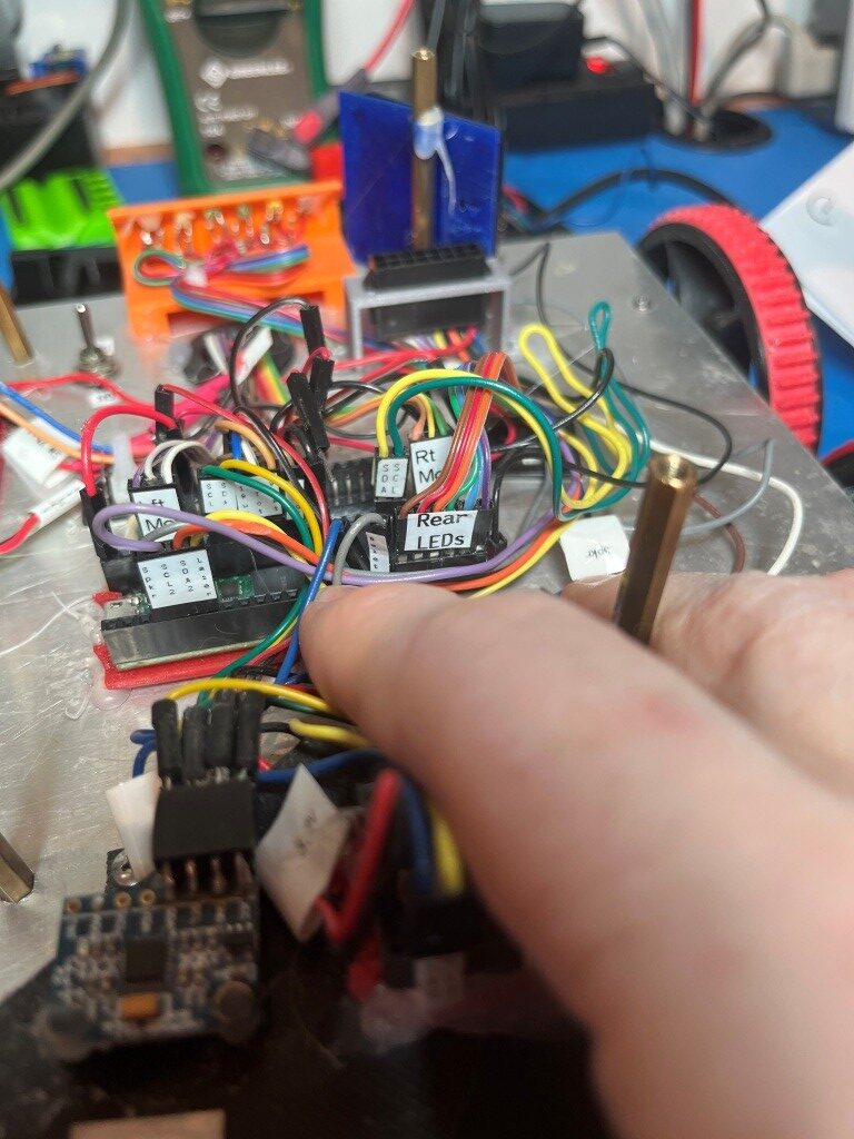
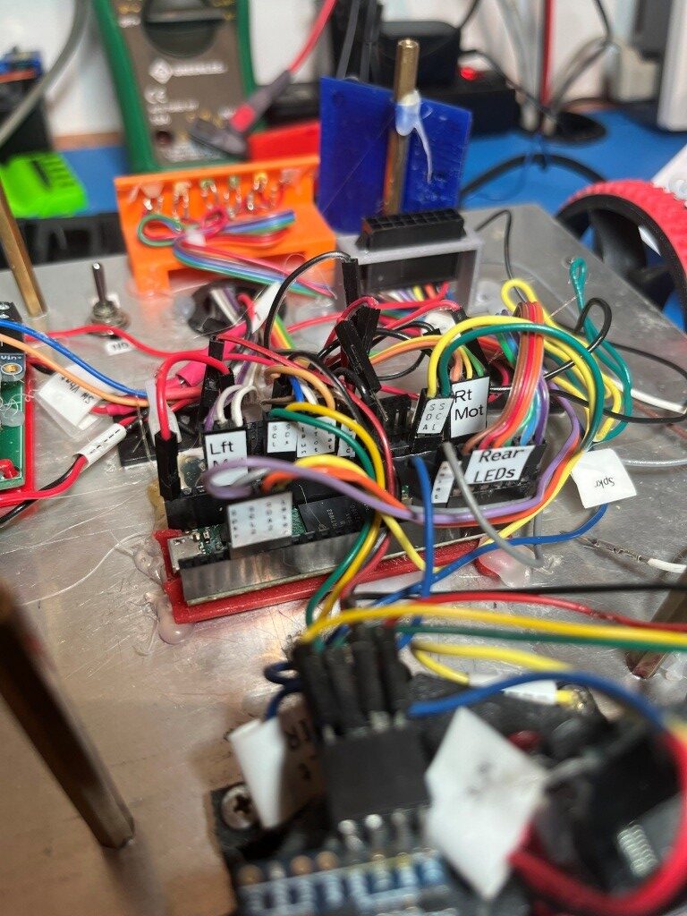
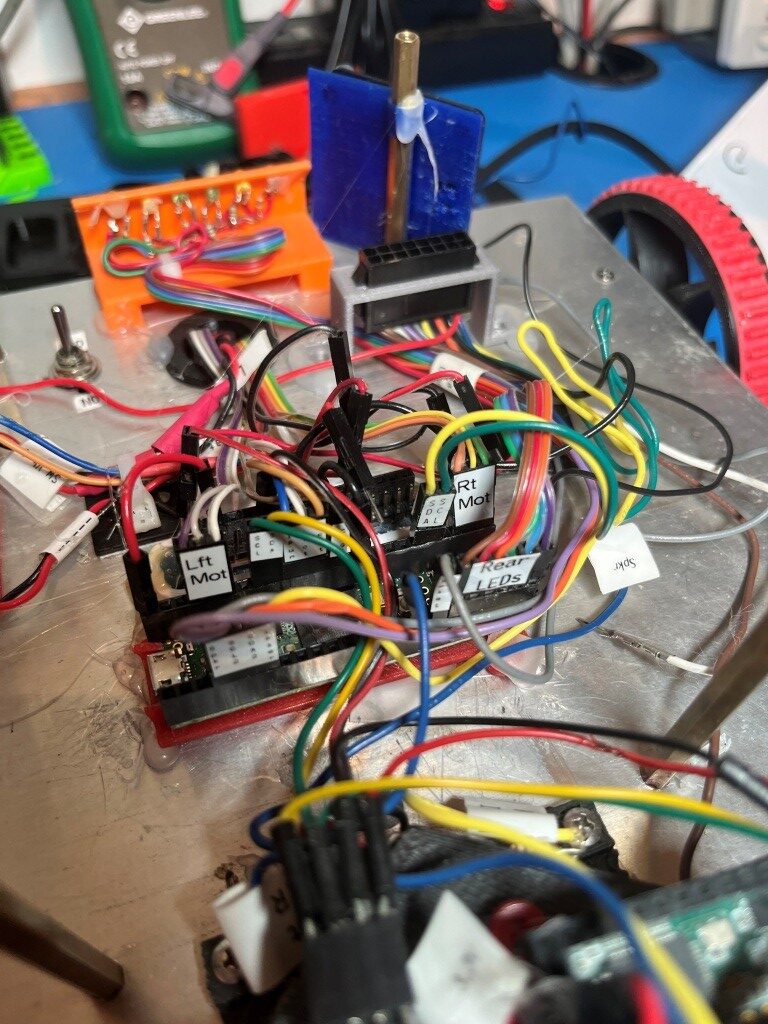
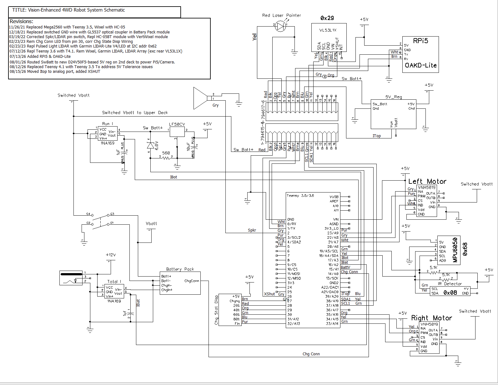
So, I have spent the last few days going backwards – from Teensy 4.1 to Teensy 3.5. I took the opportunity to improve wire/pin labelling while doing the reverse transition. Here is the updated schematic:
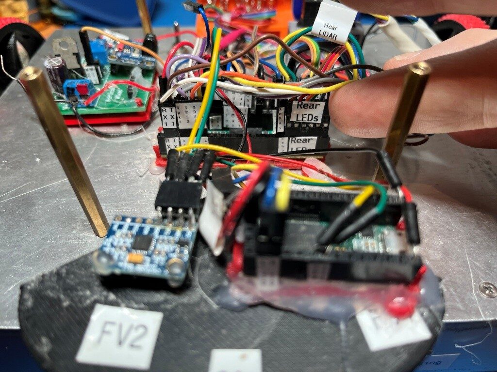
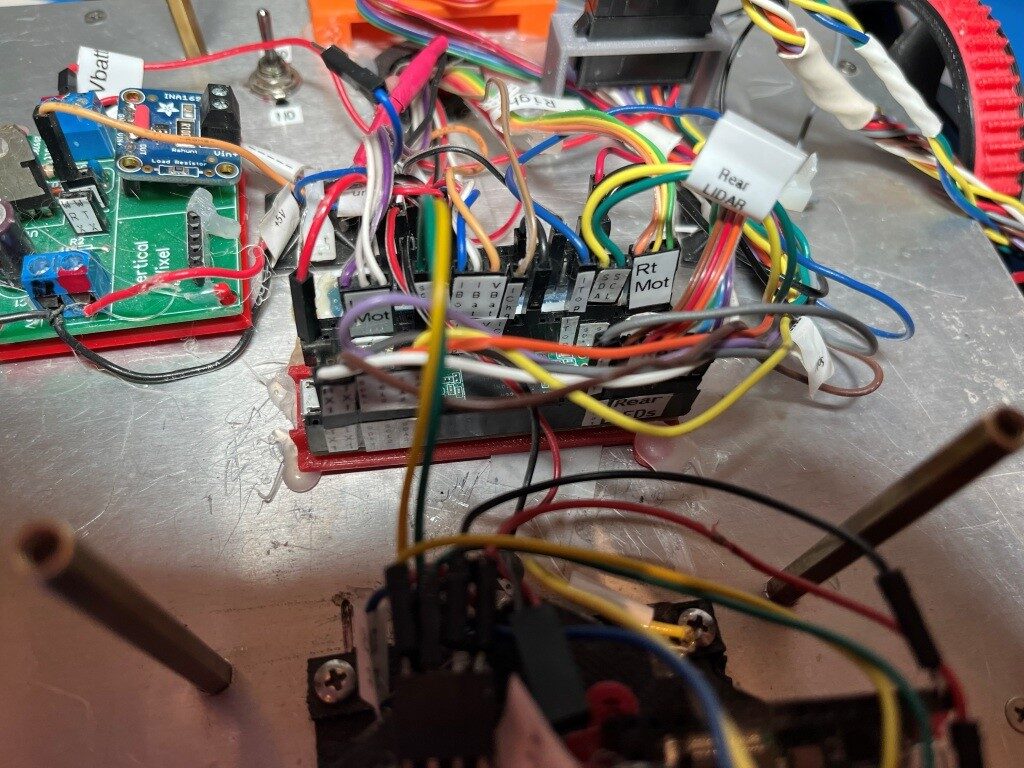
And here are some photos showing the wire labelling:
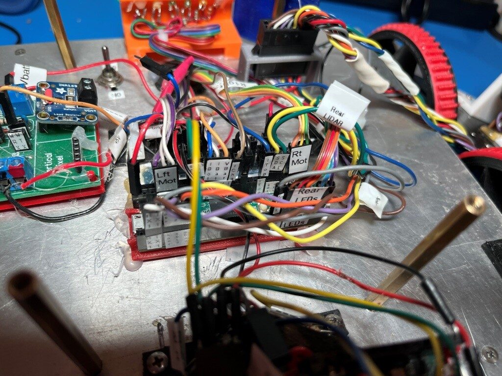
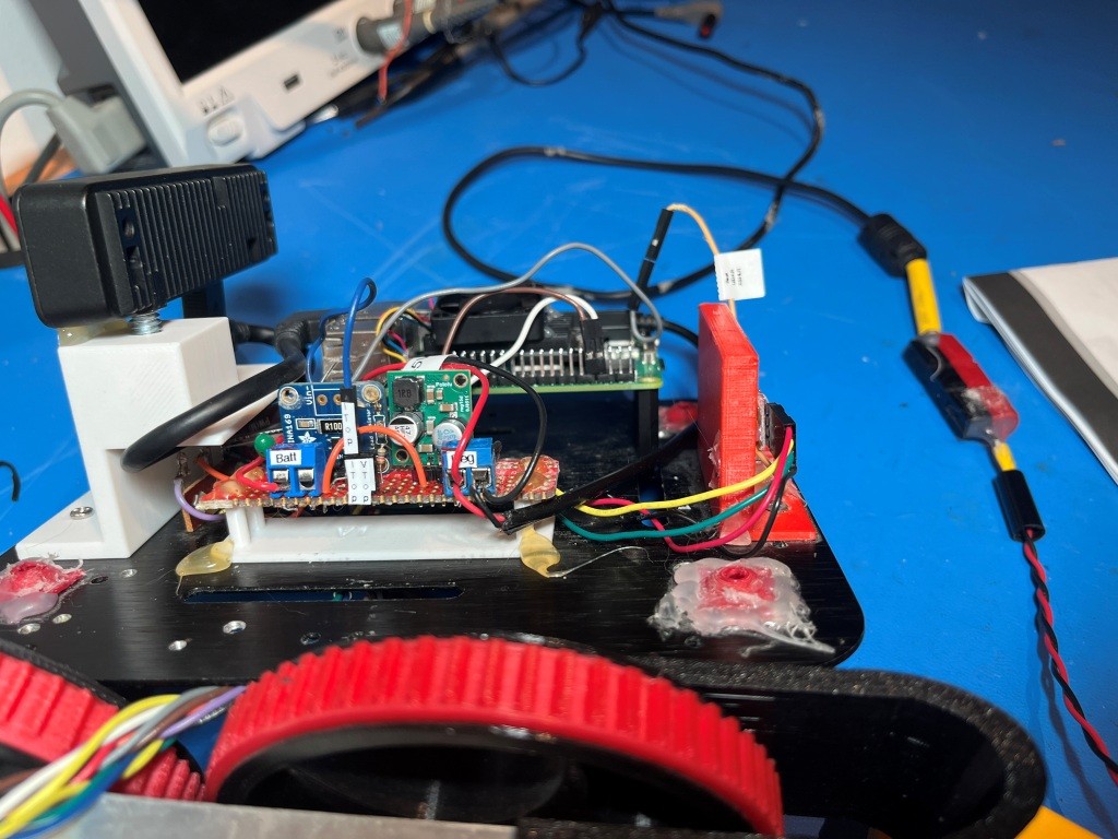
I created a small test program, originally to just test the rear-facing VL53L1X LIDAR, but later expanded to test all sensors. Here’s the code:
|
1 2 3 4 5 6 7 8 9 10 11 12 13 14 15 16 17 18 19 20 21 22 23 24 25 26 27 28 29 30 31 32 33 34 35 36 37 38 39 40 41 42 43 44 45 46 47 48 49 50 51 52 53 54 55 56 57 58 59 60 61 62 63 64 65 66 67 68 69 70 71 72 73 74 75 76 77 78 79 80 81 82 83 84 85 86 87 88 89 90 91 92 93 94 95 96 97 98 99 100 101 102 103 104 105 106 107 108 109 110 111 112 113 114 115 116 117 118 119 120 121 122 123 124 125 126 127 128 129 130 131 132 133 134 135 136 137 138 139 140 141 142 143 144 145 146 147 148 149 150 151 152 153 154 155 156 157 158 159 160 161 162 163 164 165 166 167 168 169 170 171 172 173 174 175 176 177 178 179 180 181 182 183 184 185 186 187 188 189 190 191 192 193 194 195 196 197 198 199 200 201 202 203 204 205 206 207 208 209 210 211 212 213 214 215 216 217 218 219 220 221 222 223 224 225 226 227 228 229 230 231 232 233 234 235 236 237 238 239 240 241 242 243 244 245 246 247 248 249 250 251 252 253 254 255 256 257 258 259 260 261 262 263 264 265 266 267 268 269 270 271 272 273 274 275 276 277 278 279 280 281 282 283 284 285 286 287 288 289 290 291 292 293 294 295 296 297 298 299 300 301 302 303 304 305 306 307 308 309 310 311 312 313 314 315 316 317 318 319 320 321 322 323 324 325 326 327 328 329 330 331 332 333 334 335 336 337 338 339 340 341 342 343 344 345 346 347 348 349 350 351 352 353 354 355 356 357 358 359 360 361 362 363 364 365 366 367 368 369 370 371 |
/* Name: VL53L1X_Demo.ino Created: 8/13/2026 8:09:07 PM Author: FRANK_XPS_9530\Frank */ #include <Wire.h> #include <VL53L1X.h> #include "MPU6050_6Axis_MotionApps612.h" //01/18/22 changed to use the \I2CDevLib\Arduino\MPU6050\ version VL53L1X lidar; #pragma region PIN ASSIGNMENTS const uint8_t XSHUT_PIN = 26; const uint8_t SW_BATT_VOLT_PIN = 15; const uint8_t I_TOP_PIN = 39; const uint8_t I_BOT_PIN = 17; const uint8_t I_CHG_PIN = 16; const uint8_t LASER_PIN = 5; const uint8_t SPEAKER_PIN = 2; #pragma endregion PIN ASSIGNMENTS #pragma region ADC CONSTANTS const float ADC_REF_VOLTS = 3.3; //teensy default for analog inputs const int MAX_AD_COUNT = 1023; const float AmpsPerVolt = 1.00; //default 10K Rs const float VoltsPerCount = ADC_REF_VOLTS / MAX_AD_COUNT; const float VOLTAGE_TO_CURRENT_RATIO = 1.f; //Used for both 'Total' and 'Run' sensors #pragma endregion ADC CONSTANTS const float ZENER_VOLTAGE_OFFSET = 5.96; //03/14/22 measured zener voltage const char* WallFollowTelemStr = "%2.1f\t%2.1f\t%2.1f\t%2.1f\t%2.1f\t%2.1f\t%2.2f\t%2.2f\t%2.0f\t%2.1f\t%d\t%d\t%s\t%s\n";//05/12/23 added L/R motor speeds const char* ColumnHeaderStr = "Msec\tBattV\tTop_I\tBot_I\tChg_I\tRear_mm\tHdgDeg\n"; //11/07/2020 moved all I2C Address declarations here #pragma region I2C_ADDRESSES #define IRDET_I2C_ADDR 0x08 #define MPU6050_I2C_ADDR 0x68 #pragma endregion I2C_ADDRESSES #pragma region MPU6050_SUPPORT uint8_t mpuIntStatus; // holds actual interrupt status byte from MPU. Used in Homer's Overflow routine uint8_t devStatus; // return status after each device operation (0 = success, !0 = error) uint16_t packetSize; // expected DMP packet size (default is 42 bytes) uint16_t fifoCount; // count of all bytes currently in FIFO uint8_t fifoBuffer[64]; // FIFO storage buffer // orientation/motion vars Quaternion q; // [w, x, y, z] quaternion container VectorInt16 aa; // [x, y, z] accel sensor measurements VectorInt16 aaReal; // [x, y, z] gravity-free accel sensor measurements VectorInt16 aaWorld; // [x, y, z] world-frame accel sensor measurements VectorFloat gravity; // [x, y, z] gravity vector float euler[3]; // [psi, theta, phi] Euler angle container float ypr[3]; // [yaw, pitch, roll] yaw/pitch/roll container and gravity vector int GetPacketLoopCount = 0; int OuterGetPacketLoopCount = 0; //MPU6050 status flags bool bMPU6050Ready = true; bool dmpReady = false; // set true if DMP init was successful volatile float IMUHdgValDeg = 0; //updated by UpdateIMUHdgValDeg()//11/02/20 now updated in ISR const uint16_t MAX_GETPACKET_LOOPS = 100; //10/30/19 added for backup loop exit condition in GetCurrentFIFOPacket() uint8_t GetCurrentFIFOPacket(uint8_t* data, uint8_t length, uint16_t max_loops = MAX_GETPACKET_LOOPS); //prototype here so can define a default param bool bFirstTime = true; //#define MPU6050_CCW_INCREASES_YAWVAL //added 12/05/19 commented out 11/22/21 as now the MPU6050 module is mounted 'Z-up' #pragma endregion MPU6050 Support #pragma region HEADING_AND_RATE_BASED_TURN_PARAMETERS float Prev_HdgDeg = 0; //02/01/23 - this should be a local variable in SpinTurn() float TurnRatePIDOutput; //02/01/23 - this should be a local variable in SpinTurn() //06/04/22 from WallE3_SpinTurnTuning.ino float TurnRate_Kp = 0.7;//02/03/23 updated Kp from 1.0 to 0.7 per https://www.fpaynter.com/2022/12/walle3-spin-turn-revisited/ float TurnRate_Ki = 0.3; float TurnRate_Kd = 0.0;//02/03/23 updated Kd from 0.1 to 0.0 per https://www.fpaynter.com/2022/12/walle3-spin-turn-revisited/ //ported from FourWD_PulseTurnRateTest.ino const float HDG_NEAR_MATCH_VAL = 0.8; //slow the turn down here const float HDG_FULL_MATCH_VAL = 0.99; //stop the turn here //rev 06/01/21 const float HDG_MIN_MATCH_VAL = 0.6; //added 09/08/18: don't start checking slope until turn is well started const float DEFAULT_TURN_RATE_DEGPERSEC = 45.f; //06/06/21 updated const uint16_t HEADING_HISTORY_ARRAY_SIZE = 50; //06/12/23 added for 'spinning' condx detection float gl_HdgHistoryArray[HEADING_HISTORY_ARRAY_SIZE]; //02/16/22 fwd decl reqd for fcns using default param //09/16/23 added RunBothMotorsMsec with default params //bool SpinTurn(bool b_ccw, float numDeg, float degPersec = DEFAULT_TURN_RATE_DEGPERSEC); // ////06/01/24 chg int gl_Leftspeednum to uint16_t leftspeednum, int gl_Rightspeednum to uint16_t rightspeednum ////void RunBothMotorsMsec(bool bisFwd, int timeMsec = 500, int gl_Leftspeednum = MOTOR_SPEED_HALF, int gl_Rightspeednum = MOTOR_SPEED_HALF); //void RunBothMotorsMsec(bool bisFwd, int timeMsec = 500, uint16_t leftspeednum = MOTOR_SPEED_HALF, uint16_t rightspeednum = MOTOR_SPEED_HALF); //bool RollingTurn(bool b_ccw, bool b_fwd, float numDeg, float Kp, float Ki, float Kd, float degPersec = DEFAULT_TURN_RATE_DEGPERSEC); //bool IsChargerConnected(bool curState = false); #pragma endregion HEADING_AND_RATE_BASED_TURN_PARAMETERS MPU6050 mpu(MPU6050_I2C_ADDR); void setup() { Serial.begin(115200); while (!Serial && millis() < 3000); delay(500); // Reset the sensor pinMode(XSHUT_PIN, OUTPUT); digitalWrite(XSHUT_PIN, LOW); delay(10); digitalWrite(XSHUT_PIN, HIGH); delay(20); Wire.begin(); Wire.setClock(400000); // Use Wire1 instead of Wire for rear LIDAR Wire1.begin(); Wire1.setClock(400000); lidar.setBus(&Wire1); // <-- this is the key line lidar.setTimeout(500); if (!lidar.init()) { Serial.println("Failed to detect and initialize VL53L1X on Wire1!"); while (1); } Serial.println("VL53L1X detected on Wire1 and initialized"); lidar.setDistanceMode(VL53L1X::Long); lidar.setMeasurementTimingBudget(50000); lidar.startContinuous(50); //init current sensor pins pinMode(I_BOT_PIN, INPUT); pinMode(I_TOP_PIN, INPUT); pinMode(I_CHG_PIN, INPUT); pinMode(LASER_PIN, OUTPUT); //exercise the laser diode digitalWrite(LASER_PIN, HIGH); delay(200); digitalWrite(LASER_PIN, LOW); delay(200); digitalWrite(LASER_PIN, HIGH); delay(200); digitalWrite(LASER_PIN, LOW); //Exercise the speaker tone(SPEAKER_PIN, 1000, 2000); //returns immediately #pragma region MPU6050 #ifndef NO_MPU6050 Serial.printf("\nChecking for MPU6050 IMU at I2C Addr 0x%x\n", MPU6050_I2C_ADDR); Serial.println(mpu.testConnection() ? F("MPU6050 connection successful") : F("MPU6050 connection failed")); mpu.initialize(); // verify connection float StartSec = 0; //used to time MPU6050 init Serial.println(F("Initializing DMP...")); devStatus = mpu.dmpInitialize(); // make sure it worked (returns 0 if successful) if (devStatus == 0) { // turn on the DMP, now that it's ready Serial.printf(F("Enabling DMP...\n")); mpu.setDMPEnabled(true); // set our DMP Ready flag so the main loop() function knows it's okay to use it Serial.println(F("DMP ready! Waiting for MPU6050 drift rate to settle...")); dmpReady = true; // get expected DMP packet size for later comparison packetSize = mpu.dmpGetFIFOPacketSize(); Serial.printf(F("Calibrating...Retrieving Calibration Values\n\n")); mpu.CalibrateGyro(); //using default value of 15 mpu.PrintActiveOffsets(); //loop heading display until stabilized Serial.printf(F("\nMsec\tHdg\n")); UpdateIMUHdgValDeg(); Prev_HdgDeg = IMUHdgValDeg; delay(100); UpdateIMUHdgValDeg(); Serial.printf("%lu\t%2.3f\t%2.3f\n", millis(), IMUHdgValDeg, Prev_HdgDeg); while (abs(IMUHdgValDeg - Prev_HdgDeg) > 0.1f) { Serial.printf("%lu\t%2.3f\n", millis(), IMUHdgValDeg); Prev_HdgDeg = IMUHdgValDeg; delay(100); UpdateIMUHdgValDeg(); } StartSec = millis() / 1000.f; Serial.printf("MPU6050 Ready at %2.2f Sec with delta = %2.3f\n", StartSec, IMUHdgValDeg - Prev_HdgDeg); bMPU6050Ready = true; delay(1000); } else //MPU6050 Init failed for some reason { // ERROR! // 1 = initial memory load failed // 2 = DMP configuration updates failed // (if it's going to break, usually the code will be 1) Serial.printf("DMP Initialization failed with code %d", devStatus); //08/29/21 print out battery voltage on failure //float batV = GetBattVoltage(); //gl_batteryVoltage = GetBattVoltage(); //Serial.printf("Battery Voltage = %2.2f\n", gl_batteryVoltage); bMPU6050Ready = false; } #endif // !NO_MPU6050 #pragma endregion MPU6050 //Serial.printf("Msec\tBattV\tTop_I\tBot_I\tChg_I\tRear_mm\n"); Serial.printf(ColumnHeaderStr); } void loop() { //rear-facing VL53L1X uint16_t rear_mm = lidar.read(); //Serial.print(rear_mm); if (lidar.timeoutOccurred()) { Serial.print(" TIMEOUT"); } //04/02/21 moved to 'fast' part of loop float BattV = GetVoltage(SW_BATT_VOLT_PIN); float TopI = GetAmps(I_TOP_PIN); float BotI = GetAmps(I_BOT_PIN); float ChgI = GetAmps(I_CHG_PIN); UpdateIMUHdgValDeg(); //updatees IMUHdgValDeg //Serial.printf("\Msec\tBattV\tTop_I\tBot_I\tChg_I\tRear_mm\n"); Serial.printf("%lu\t%2.2f\t%2.2f\t%2.2f\t%2.2f\t%d\t%2.2f\n", millis(), BattV, TopI, BotI, ChgI, rear_mm, IMUHdgValDeg ); delay(100); } float GetAmps(int pin_number) { //Purpose: Get current in amps //Inputs: // pin_number = integer denoting analog pin to be used for measurement // VOLTAGE_TO_CURRENT_RATIO = measured voltage to current ratio // MAX_AD_COUNT = int denoting max A/D reading value // VOLTAGE_TO_CURRENT_RATIO = int denoting conversion ratio //Outputs: // returns total robot current (chg current plus running current) //Notes: // 02/28/18 chg name from GetBattChgAmps() to GetTotalAmps() // 11/24/21 chg name, add pin_number param so can use for both Itot & Irun int reading = analogRead(pin_number); //range is 0-1023 float volts = ((float)reading / (float)MAX_AD_COUNT) * ADC_REF_VOLTS; float amps = volts * VOLTAGE_TO_CURRENT_RATIO; //DEBUG!! //Serial.printf("GetAmps(%d): reading, volts, amps = %d, %3.2f, %3.2f\n", // pin_number, reading, volts, amps); //DEBUG!! return amps; } float GetVoltage(uint8_t volt_pin) { //02/18/17 get corrected battery voltage. Voltage reading is 1/3 actual Vbatt value int analog_batt_reading = analogRead(volt_pin);//analogReadAveraging(8) in setup() does internal averaging float calc_volts = ZENER_VOLTAGE_OFFSET + ADC_REF_VOLTS * (float)analog_batt_reading / (float)MAX_AD_COUNT; //DEBUG!! //for(int i = 0; i < 8;i++) //{ // int analog_batt_reading = analogRead(BATT_MON_PIN);//analogReadAveraging(8) in setup() does internal averaging // float calc_volts = ZENER_VOLTAGE_OFFSET + ADC_REF_VOLTS * (float)analog_batt_reading / (float)MAX_AD_COUNT; // gl_pSerPort->printf("a/d = %d, calc = %2.2f\n", analog_batt_reading,calc_volts); // delay(100); //} //DEBUG!! return calc_volts; } float UpdateIMUHdgValDeg() { //Purpose: Get latest yaw (heading) value from IMU //Inputs: None. This function should only be called after mpu.dmpPacketAvailable() returns TRUE //Outputs: // returns true if successful, otherwise false // IMUHdgValDeg updated on success //Plan: //Step1: check for overflow and reset the FIFO if it occurs. In this case, wait for new packet //Step2: read all available packets to get to latest data //Step3: update IMUHdgValDeg with latest value //Notes: // 10/08/19 changed return type to boolean // 10/08/19 no longer need mpuIntStatus // 10/21/19 completely rewritten to use Homer's algorithm // 05/05/20 changed return type to float vs bool. // 06/13/23 added code to update gl_HdgHistoryArray for 'spinning' condx detection int flag = GetCurrentFIFOPacket(fifoBuffer, packetSize, MAX_GETPACKET_LOOPS); //get the latest mpu packet if (flag != 0) //0 = error exit, 1 = normal exit, 2 = recovered from an overflow { // display Euler angles in degrees mpu.dmpGetQuaternion(&q, fifoBuffer); mpu.dmpGetGravity(&gravity, &q); mpu.dmpGetYawPitchRoll(ypr, &q, &gravity); //compute the yaw value IMUHdgValDeg = ypr[0] * 180 / M_PI; } //06/13/23 added to update gl_HdgHistoryArray for 'spinning' condx detection //all array entries bumped down one, with most recent value at i = HEADING_HISTORY_ARRAY_SIZE-1 for (uint16_t i = 1; i < HEADING_HISTORY_ARRAY_SIZE; i++) { gl_HdgHistoryArray[i - 1] = gl_HdgHistoryArray[i]; //gl_pSerPort->printf("gl_HdgHistoryArray[%d] = %2.2f\n", i, gl_HdgHistoryArray[i]); } gl_HdgHistoryArray[HEADING_HISTORY_ARRAY_SIZE - 1] = IMUHdgValDeg; return IMUHdgValDeg;//05/05/20 now returns updated value for use convenience } uint8_t GetCurrentFIFOPacket(uint8_t* data, uint8_t length, uint16_t max_loops) { mpu.resetFIFO(); delay(1); //int countloop = 0; fifoCount = mpu.getFIFOCount(); GetPacketLoopCount = 0; //gl_pSerPort->printf("In GetCurrentFIFOPacket: before loop fifoC = %d\t", fifoCount); while (fifoCount < packetSize && GetPacketLoopCount < max_loops) { GetPacketLoopCount++; fifoCount = mpu.getFIFOCount(); delay(2); } //gl_pSerPort->printf("In GetCurrentFIFOPacket: after loop fifoC = %d, loop count = %d\n", fifoCount, GetPacketLoopCount); if (GetPacketLoopCount >= max_loops) { return 0; } //if we get to here, there should be exactly one packet in the FIFO mpu.getFIFOBytes(data, packetSize); return 1; } |
And here’s the output showing all three current sensors, the battery voltage, and the rear-facing VL53L1X LIDAR output (variations in the rear distanced are due to my waving my hand in front of the sensor).
|
1 2 3 4 5 6 7 8 9 10 11 12 13 14 15 16 17 18 19 20 21 22 23 24 25 26 27 28 29 30 31 32 |
Opening port Port open VL53L1X detected on Wire1 and initialized Msec BattV Top_I Bot_I Chg_I Rear_mm 1056 7.77 0.33 0.00 0.23 3607 1158 7.81 0.30 0.00 0.23 3622 1259 7.81 0.31 0.00 0.23 3658 1360 7.81 0.30 0.00 0.23 3639 1461 7.84 0.46 0.00 0.23 3659 1562 7.99 0.29 0.00 0.23 3606 1663 7.89 0.30 0.00 0.23 481 1764 7.86 0.34 0.00 0.23 48 1865 7.92 0.30 0.00 0.23 60 1966 7.92 0.30 0.00 0.22 62 2067 7.94 0.29 0.00 0.23 75 2169 7.92 0.29 0.00 0.22 2400 2270 7.92 0.30 0.00 0.22 3675 2371 7.90 0.31 0.00 0.22 3761 2472 7.92 0.30 0.00 0.22 3739 2573 7.90 0.30 0.00 0.22 28 2674 7.91 0.31 0.00 0.22 0 2775 7.91 0.31 0.00 0.22 61 2876 7.89 0.30 0.00 0.22 59 2977 7.90 0.30 0.00 0.22 2406 3078 7.89 0.34 0.00 0.22 3657 3180 7.93 0.30 0.00 0.20 3688 3281 7.89 0.30 0.00 0.23 3619 3382 7.89 0.30 0.00 0.22 13 3483 7.88 0.31 0.00 0.22 0 3584 7.94 0.29 0.00 0.23 85 3685 7.90 0.30 0.00 0.22 3533 3786 7.91 0.31 0.00 0.22 3713 |
I wasn’t quite sure what to make of the zero readings for Bot_I, but then I realized that when the USB cable is plugged into the Teensy 3.5, it provides all the current needed for the first deck peripherals, meaning the current through the Bot_I INA169 sensor is essentially zero.
Next I ported the MPU-6050 support code from the VisionEnhanced4WheelRobot project into my little demo program and put some code in ‘loop()’ to add the IMU heading output to the sensor line. This didn’t work at first, but with Grok’s help I traced the problem to a disconnected power/ground lead from the main power distribution bus to the MPU6050. Once this was connected, the demo program started working right away:
|
1 2 3 4 5 6 7 8 9 10 11 12 13 14 15 16 17 18 19 20 21 22 23 24 25 26 27 28 29 30 31 32 33 34 35 36 37 38 39 40 41 42 43 44 |
Opening port Port open VL53L1X detected on Wire1 and initialized Checking for MPU6050 IMU at I2C Addr 0x68 MPU6050 connection successful Initializing DMP... Enabling DMP... DMP ready! Waiting for MPU6050 drift rate to settle... Calibrating...Retrieving Calibration Values ...............1800.00000, 1415.00000, 772.00000, -65.00000, 18.00000, 22.00000 Msec Hdg 2084 0.106 0.105 MPU6050 Ready at 2.08 Sec with delta = 0.002 Msec BattV Top_I Bot_I Chg_I Rear_mm HdgDeg 3094 8.06 0.26 0.00 0.01 3082 0.12 3206 8.06 0.27 0.00 0.00 2987 0.12 3320 8.06 0.26 0.00 0.02 3154 0.13 3432 8.06 0.27 0.00 0.00 3021 0.13 3544 8.07 0.26 0.00 0.00 3117 0.13 3656 8.06 0.27 0.00 0.02 3010 0.13 3767 8.05 0.29 0.00 0.02 3208 0.13 ... Rotated robot by hand... 7468 8.05 0.28 0.00 0.02 3210 0.87 7580 8.05 0.26 0.00 0.02 3211 1.50 7691 8.06 0.27 0.00 0.00 2740 2.80 7803 8.06 0.29 0.00 0.00 3078 5.25 7917 8.06 0.29 0.00 0.02 3039 7.86 8029 8.07 0.26 0.00 0.00 3166 11.13 8141 8.06 0.28 0.00 0.00 3177 13.85 8253 8.07 0.26 0.00 0.02 3130 15.74 8364 8.05 0.26 0.00 0.02 2720 15.77 8476 8.05 0.28 0.00 0.02 2926 15.56 8588 8.07 0.27 0.00 0.00 3193 14.39 8702 8.05 0.30 0.00 0.00 2921 11.06 8814 8.06 0.26 0.00 0.03 2501 7.14 8926 8.05 0.29 0.00 0.00 2724 4.01 9037 8.04 0.27 0.00 0.00 2883 -0.51 9149 8.04 0.28 0.00 0.02 3158 -5.95 9261 8.05 0.27 0.00 0.02 3199 -10.29 9373 8.04 0.29 0.00 0.02 2951 -13.32 9487 8.05 0.28 0.00 0.00 2966 -15.82 9599 8.05 0.27 0.00 0.02 2856 -17.55 9710 8.06 0.28 0.00 0.03 2790 -17.41 |
I also installed and tested a front-facing red laser diode and exercised the on-board speaker. At this point I believe I have exercised/tested all the sensors, the laser diode and the speaker. I haven’t run the motors with this program as I believe that will happen when I get back to the ‘mainline’ VisionEnhanced4WheelRobot.ino program.
16 August 2026 Update:
I back-ported the code from my VL53L1X_Demo program back to my VisionEnhanced4WheelRobot program and after the normal number of mistakes, got it going. Here’s a small bit of output from loop(), with me rotating the robot back and forth to show variation in the ‘Hdg’ and ‘RearCm’ values:
|
1 2 3 4 5 6 7 8 9 10 11 12 13 14 15 16 17 18 19 20 21 22 23 24 25 26 27 28 29 30 31 32 33 34 35 36 37 38 39 40 41 42 43 44 45 46 47 48 49 50 51 52 53 54 55 56 57 58 59 60 61 62 63 64 65 66 67 68 69 70 71 72 73 74 75 76 77 78 79 80 |
Opening port Port open In setup() just before EnableAllRearLEDs Serial port active gl_pSerPort now points to active Serial (USB or Wixel) VL53L1X detected on Wire1 and initialized Checking for MPU6050 IMU at I2C Addr 0x68 MPU6050 connection successful Initializing DMP... Enabling DMP... DMP ready! Waiting for MPU6050 drift rate to settle... Calibrating...Retrieving Calibration Values >...............1800.00000, 1415.00000, 772.00000, -71.00000, 17.00000, 25.00000 Msec Hdg 8325 0.091 0.026 MPU6050 Ready at 8.33 Sec with delta = 0.065 Time BattV TopI BotI ChgI RearCm Hdg 9338 8.15 0.24 0.00 0.23 32.10 0.67 9546 8.16 0.24 0.00 0.23 33.80 0.61 9754 8.15 0.26 0.00 0.24 34.20 0.54 9962 8.14 0.23 0.00 0.23 34.40 0.50 10170 8.16 0.23 0.00 0.23 34.50 0.49 10377 8.14 0.25 0.00 0.23 34.30 0.48 10587 8.15 0.24 0.00 0.23 34.20 0.85 10795 8.15 0.23 0.00 0.23 34.20 6.13 11003 8.15 0.23 0.00 0.23 33.60 20.67 11211 8.14 0.24 0.00 0.23 36.20 34.39 11419 8.14 0.24 0.00 0.24 40.10 46.03 11627 8.14 0.26 0.00 0.23 46.60 59.08 11837 8.15 0.25 0.00 0.24 55.20 72.07 12045 8.14 0.24 0.00 0.23 60.50 82.54 12253 8.15 0.24 0.00 0.23 69.50 85.32 12460 8.15 0.25 0.00 0.24 63.50 80.64 12668 8.13 0.25 0.00 0.23 59.00 73.99 12876 8.14 0.23 0.00 0.23 55.60 65.12 13084 8.15 0.24 0.00 0.23 47.50 53.90 13294 8.13 0.25 0.00 0.23 43.10 43.33 13502 8.15 0.23 0.00 0.23 38.20 28.72 13710 8.14 0.26 0.00 0.23 36.50 16.64 13918 8.15 0.25 0.00 0.24 35.70 6.20 14126 8.14 0.24 0.00 0.23 36.00 -4.59 14334 8.15 0.24 0.00 0.23 38.00 -16.53 14544 8.15 0.24 0.00 0.23 25.10 -25.39 14751 8.13 0.26 0.00 0.23 25.20 -32.30 14959 8.13 0.27 0.00 0.23 27.80 -39.25 15167 8.15 0.24 0.00 0.23 43.50 -44.88 15375 8.14 0.24 0.00 0.22 41.80 -48.53 15583 8.13 0.24 0.00 0.23 41.90 -46.46 15793 8.15 0.25 0.00 0.23 42.60 -40.06 16001 8.16 0.24 0.00 0.23 22.50 -31.43 16209 8.15 0.24 0.00 0.23 28.40 -20.93 16417 8.13 0.24 0.00 0.23 35.30 -10.16 16624 8.13 0.28 0.00 0.24 34.40 0.62 16832 8.13 0.24 0.00 0.23 34.20 8.56 17042 8.14 0.27 0.00 0.24 34.20 12.15 17250 8.15 0.23 0.00 0.23 34.20 11.33 17458 8.14 0.25 0.00 0.23 34.10 11.22 17666 8.12 0.27 0.00 0.22 34.10 11.25 17874 8.13 0.23 0.00 0.24 3.60 11.22 18082 8.15 0.24 0.00 0.24 3.80 11.24 18292 8.11 0.31 0.00 0.23 2.60 11.24 18500 8.14 0.25 0.00 0.23 54.30 11.23 18707 8.13 0.25 0.00 0.23 34.20 11.21 18915 8.14 0.25 0.00 0.23 34.30 11.20 19123 8.15 0.24 0.00 0.23 34.30 11.19 19331 8.15 0.24 0.00 0.23 34.10 11.17 19541 8.17 0.24 0.00 0.23 34.20 11.16 19749 8.14 0.24 0.00 0.23 33.90 11.13 19957 8.14 0.24 0.00 0.22 34.30 11.11 20165 8.14 0.25 0.00 0.23 34.40 11.10 20373 8.15 0.25 0.00 0.24 34.10 11.08 20581 8.14 0.25 0.00 0.23 34.30 11.07 20789 8.14 0.25 0.00 0.23 34.20 11.04 20999 8.15 0.25 0.00 0.23 34.30 11.03 Port closed |
Then I fired up the VS Code connection to the pi5, started WallE_5.py supervisor program and verified that I could send motor commands in the WallE_5.py window and have the robot respond appropriately – yay. I also verified that ‘tail -f ./logs/telemetry.log’ in a separate VS Code terminal window produced the same telemetry output as above.
17 August 2026 Update:
I finally have the ‘VisionEnhanced4WheelRobot’ program running again with a Teensy 3.5. The last little bit was undoing the change in motor control pin assignments for the right-hand motor driver. Going from Teenys 3.5 to 4.1 I had to change the pin assignments to place the ‘speed’ pin on a PWM-able output pin, and going back I didn’t initially undo this pin assignment – all fixed now.
At this point the robot firmware is pretty much complete – it correctly monitors all three current sensors, the battery voltage, the current heading, and the rear distance reading. I think the next step is to work on the python side to add more navigation and obstacle-avoidance ‘smarts’.
Stay tuned!
Frank