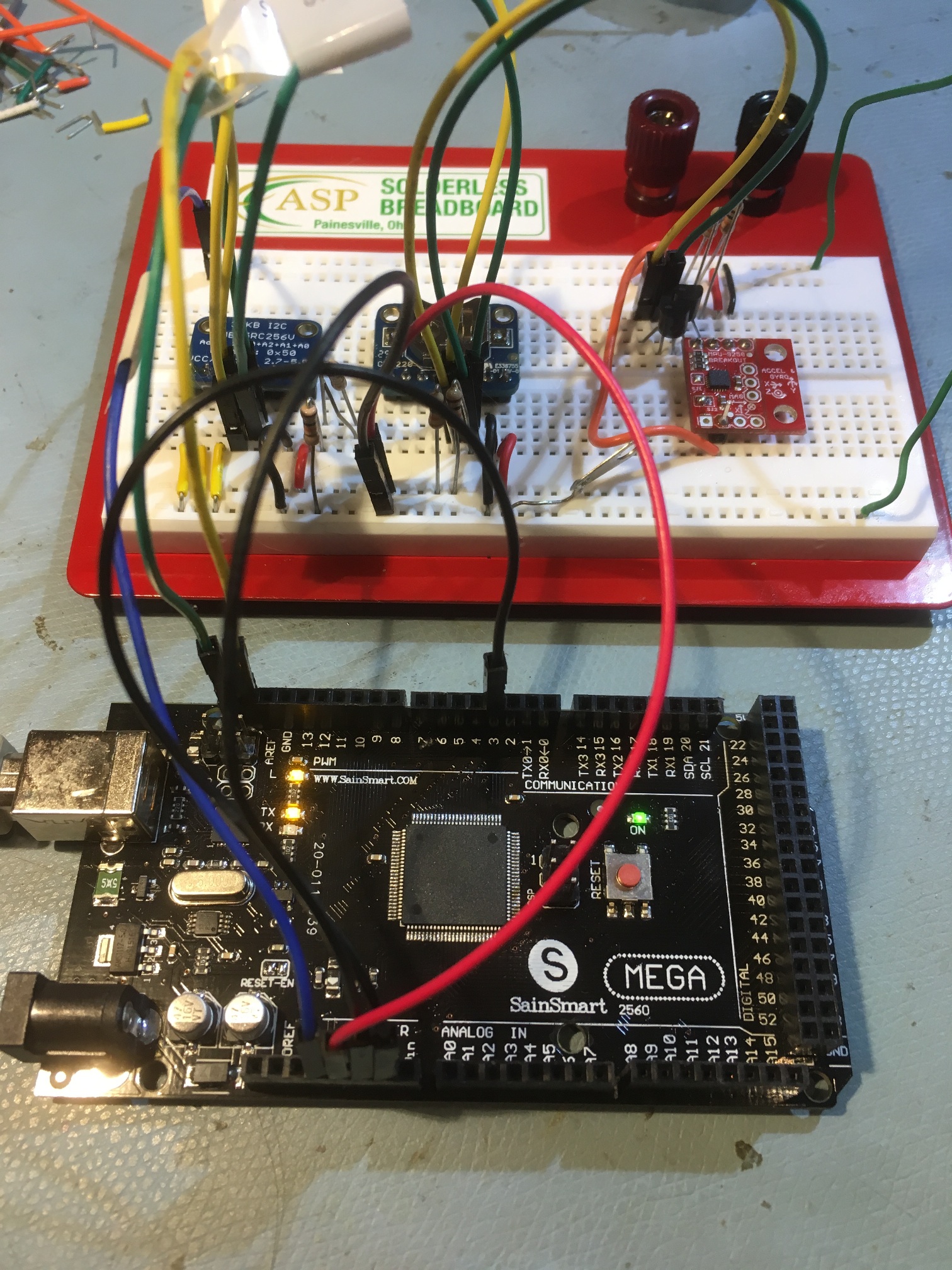
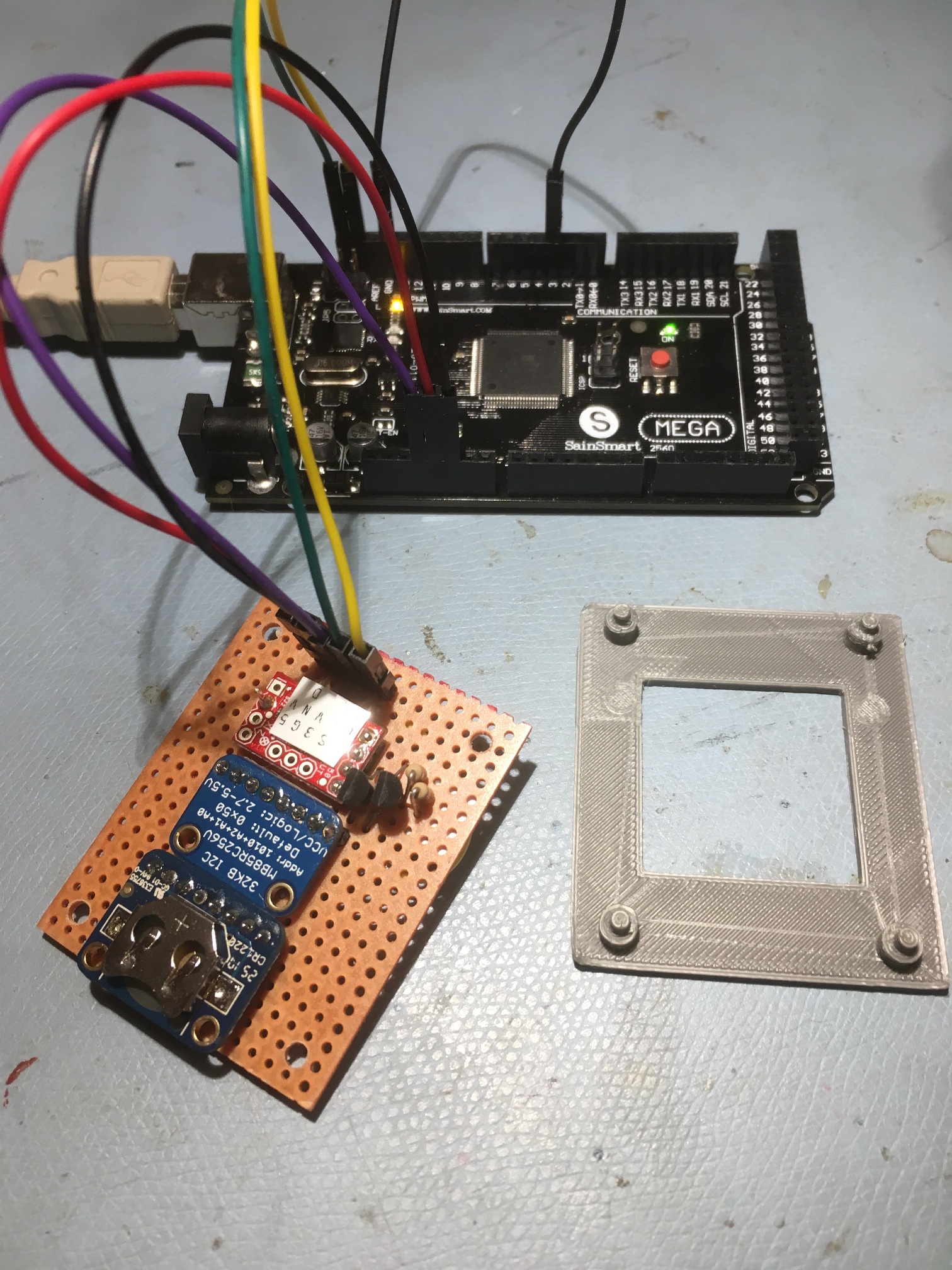
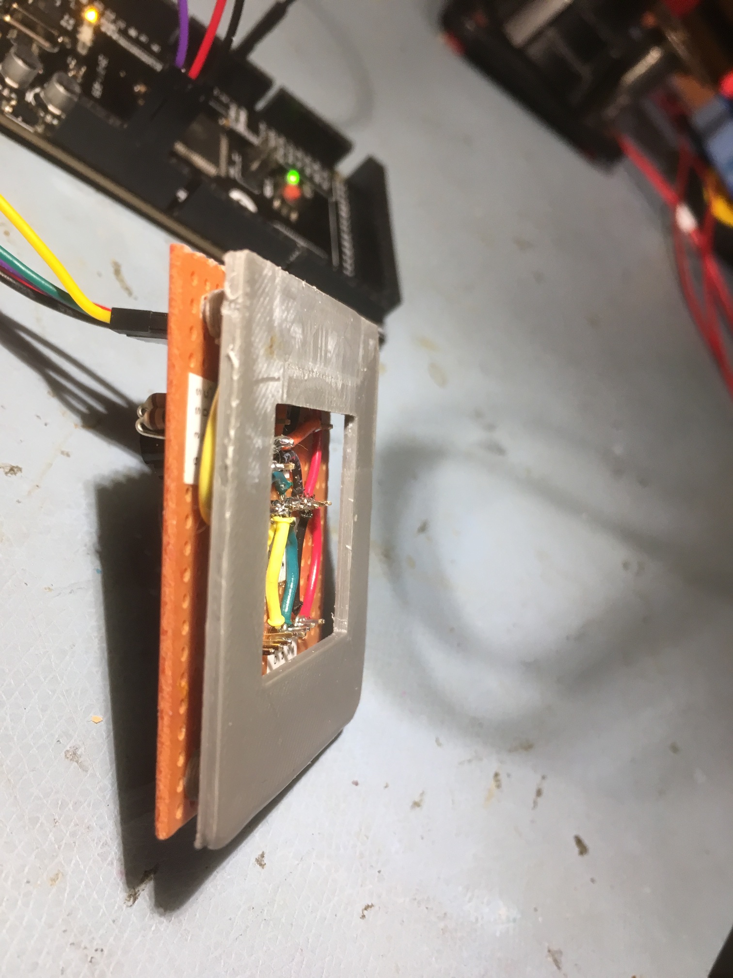
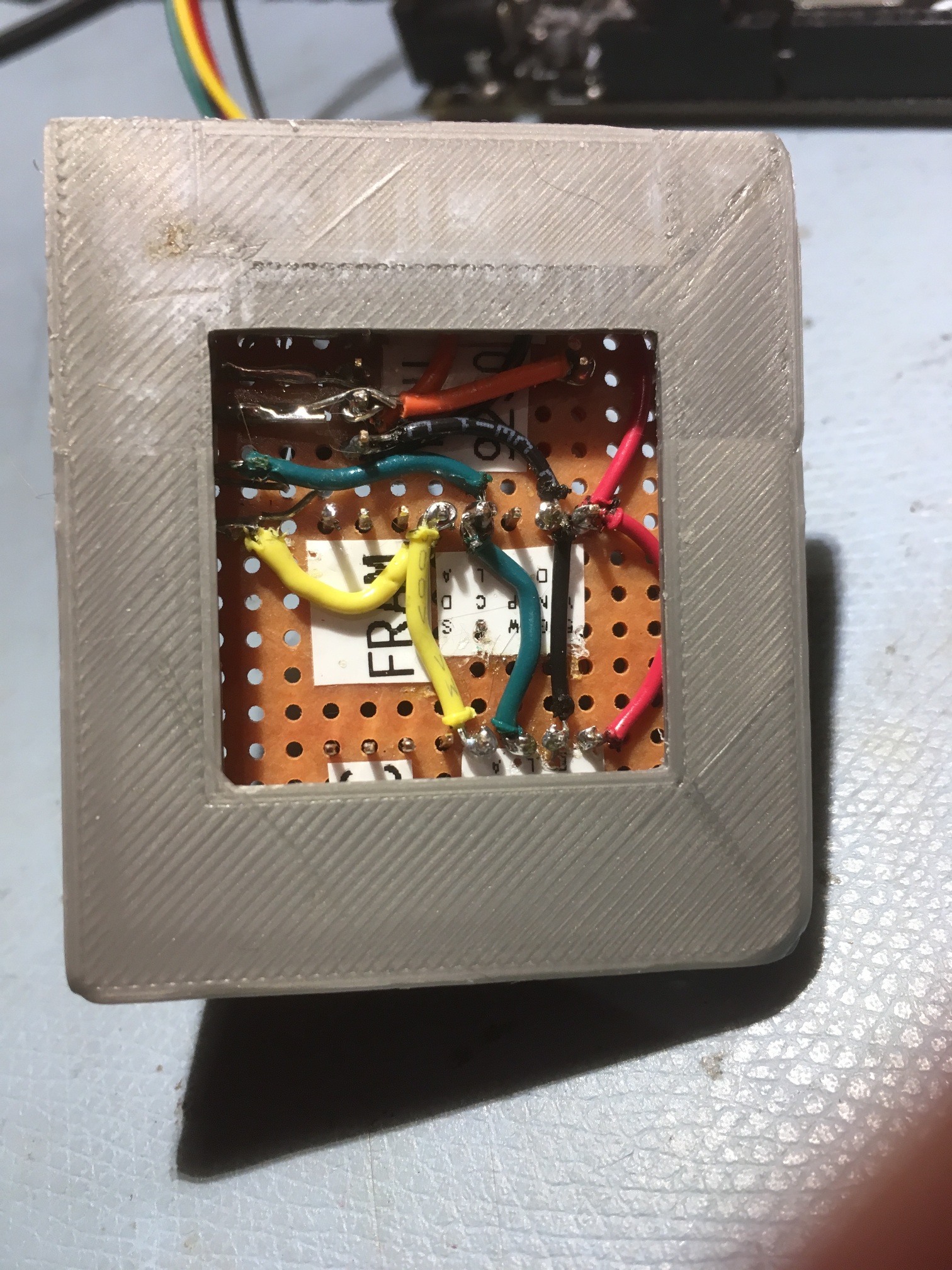
A little over two years ago I started a project to give Wall-E2 ‘a sense of direction‘ by integrating a Mongoose 9DOF IMU board onto the robot chassis. I worked on the idea for about six months before I finally determined that the magnetometer idea was not going to work in my indoor environment, as there was just too much magnetic interference due to indoor wiring, air handling motors, and the like.
However, it recently occurred to me that although the absolute magnetic heading problem was intractable, I might be able to use one of the newer single-board IMU products (like the Sparkfun 9250) to generate relative heading information, which I could use to solve a different problem. Wall-E2 occasionally needs to perform sharp turns, on the order of 90 º, either as part of what I call an ‘open room step turn’ (like what happens when Wall-E2 exits a hallway into an open room, and needs to turn 90 º in one direction or the other to continue wall-following), or as part of an evasion maneuver or as part of a recovery from a stuck condition. In my ‘field’ testing to date I have noticed that Wall-E2’s effective turn rate varies considerably depending on the surface condition; very slow on shag carpeting, OK on tightly-woven rugs, and very fast on hard flooring. This means that my current strategy of timed turns only works OK on the medium surfaces, but sucks the big weenie on the other two types. So, if I had even relative heading information, I could use it to make sure Wall-E2’s 90 º turns are actually 90 º, as opposed to 45 º or 180 º.
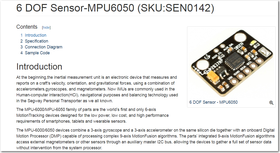
It turns out there are a lot of single-board IMU solutions out there new, probably due to the wildly popular quad-copter market; they all need attitude-control (AHRS) module of some kind to make them flyable, and those modules need to be small and lightweight. The one I started playing with first is the Sparkfun MPU-9250 breakout board, with 3-axis accelerometer, gyro, and magnetometer capability in a really small package for an incredibly cheap price. And, as a bonus, there is a lot of good Arduino/Teensyduino software out there to help us mere mortals run the thing. In particular, Kris Winer (of Pesky Products fame) has done a lot of work with sensor fusion software for the Arduino and Teensy line, and actively supports both his products and his software.
So, I got a board from Sparkfun and started playing around with it. The first problem I ran into is that the MPU9250 is a 3.3V board, so I couldn’t run it from an Arduino without either potentially frying the board or having to implement a bidirectional level shifter. So, I grabbed a Teensy 3.2 from my stash and used it instead. This, in turn, required some judicious sifting through the available software to find the Teensy 3.x compatible versions, but I eventually got that accomplished and started collecting data.
As usual, there were a lot of mis-steps along the way. The biggest obstacle was figuring out how to avoid using the magnetometer data; almost all the software, including the all-important Madgwick quaternion routine for converting raw sensor data into yaw/pitch/roll values assumes the use of magnetometer data to obtain geo-magnetically referenced heading and to minimize/eliminate gyro drift. In my case, I specifically wanted to decouple heading calculations from magnetometer input, as I already knew the magnetic environment in my house was too variable for reliable measurements. With some guidance from Kris, I eventually found a 6DOF (3D rate gyro and 3D accelerometer) version of the Madgwick routine.
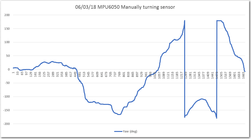
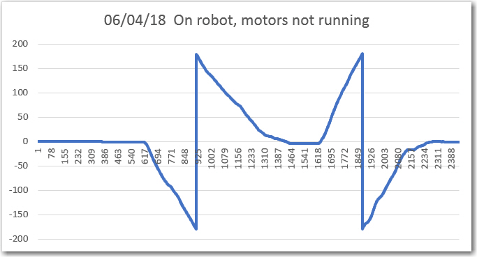
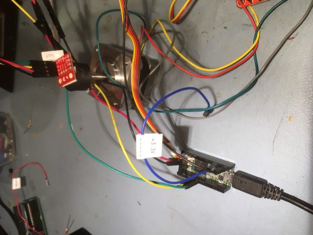
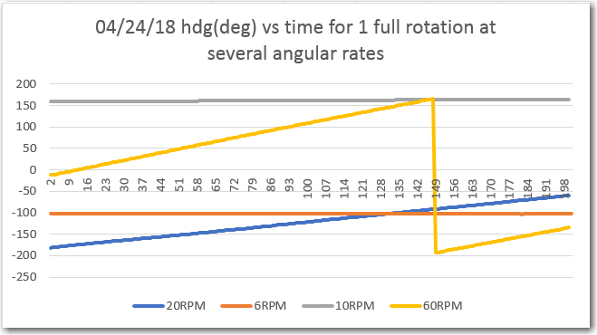
Once I started getting reliable yaw (heading) measurements from the sensor, I decided to modify my Teensy-based stepper motor rotary table measurement system to rotate the sensor in a uniform way to obtain constant-rate heading scan data. The basic idea of the rotary table system is to rotate the unit under test X degrees, then stop, take some measurements, and then repeat. So, I got it all set up, and got the following plot.
This data made no sense at all – for a full 360 º rotation I should have recorded a full 360 º heading change, regardless of the rate of rotation. Instead, the sensor seemed numb to rotation rates below about 20 rpm (120dps) and even at 60 rpm (360 dps) I wasn’t seeing a full 360 º rotation – what the heck??
After beating on this problem for waaaayyy too long, it finally occurred to me that my test program had a fatal flaw; my measurement system stepped to each desired heading, then stopped, took a heading measurement, and then moved on to the next heading. The operative word here being stopped. While this works great for units under test whose performance varies with rotation, the Sparkfun sensor performance varies with rotationrate, not the rotation position! Well, doh – it’s an accelerometer! So, my carefully assembled test setup wasn’t measuring the sensor’s rotation rate at all – the rotation rate was being reduced to almost zero at each measurement position – oops!
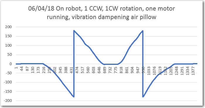
After this “aha!” (or maybe, “doh!”) moment, I realized I needed to modify my rotary test system to make sure that heading data acquisition from the sensor was accomplished ‘on the fly’. Once I did this, I started getting more reasonable data, like the following plot:
Nice, linear data – great!
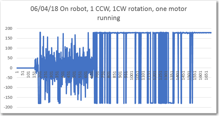
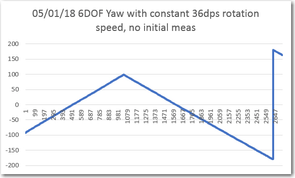
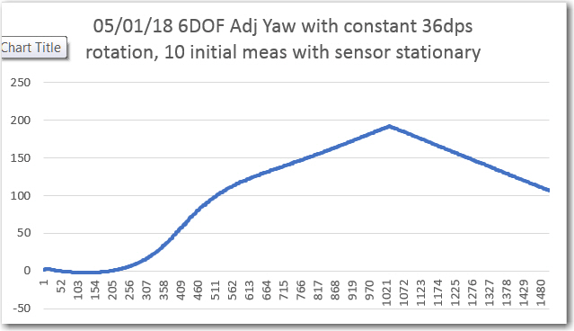
At this point I started thinking about how I could integrate this capability into my robot to monitor/manage turn operations, and thought that I could maybe average the first few heading values before the start of a turn to create a stable reference to be used to terminate the turn appropriately. However, when I tried this trick, with a 10-sample average at the start, I got the following plot
I performed the ‘with’ and ‘without’ initial measurement average experiments several times, and convinced myself that the above phenomenon was real, but I still have no real idea why it occurs. It has to have something to due with the Madgwick quaternion manipulations, as that is the only place in the entire system where there is any state memory (the 4-element quaternion array itself). For my purposes, it was sufficient to realize I couldn’t do what I wanted to do, and to “run away!” from this idea.
Next, I modified my stepper motor rotator test system again to simulate the process of setting up a turn direction and angle and terminating the turn when the correct turn angle change had been achieved. Here’s a short video of the result, where the sensor is turned through +/- 30, 60, 90, and 180 º angles. The motor is run at a constant rate until the target angle is approached, and then run at 1/5 normal speed to fine-tune turn termination.
So, at this point I confident that I can use the Sparkfun MPU9250 9DOF sensor (used in 6DOF mode) to accurately turn my robot – cool!
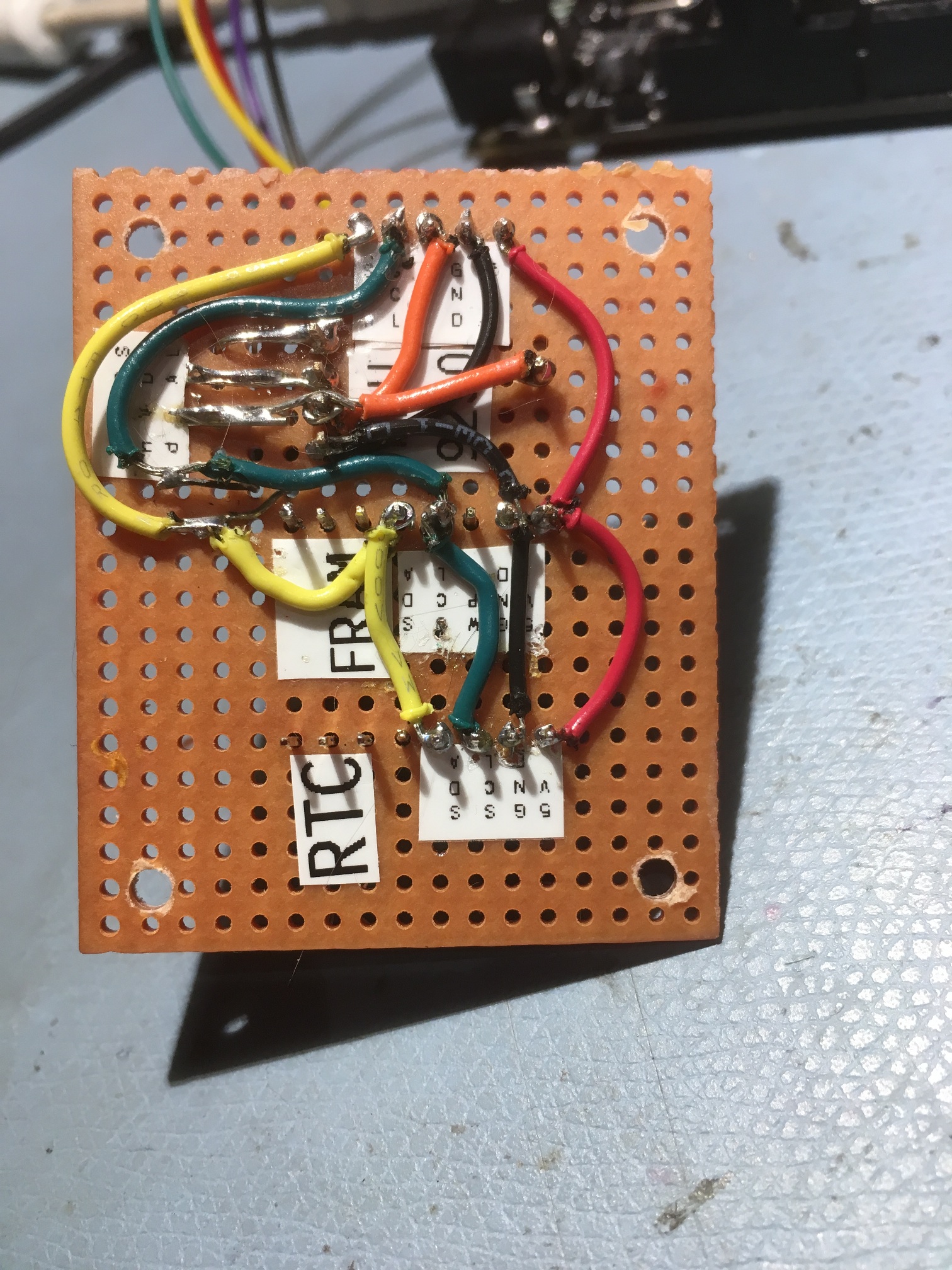
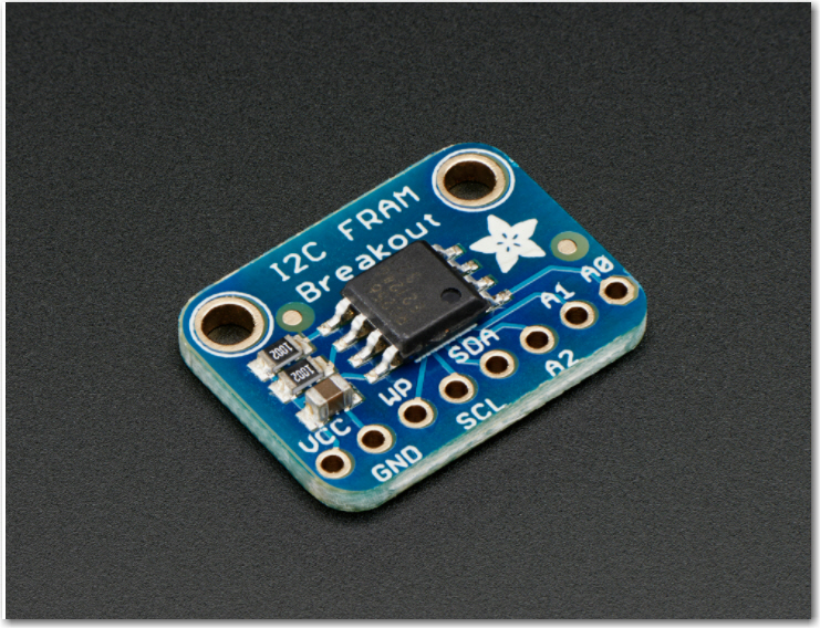
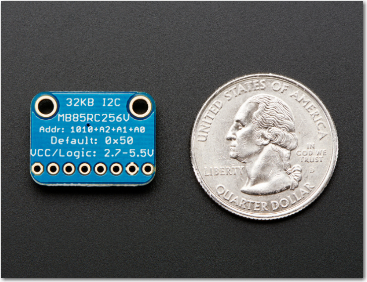
With the addition of the Sparkfun accelerometer and the FRAM/RTC combination to his sensor suite, Wall-E2 is set to get significantly smarter; he’ll be able to remember when he was last turned off so he can more accurately report run times and charge times, and he’ll be able to make real 90 º turns instead of having to fake it with timing. Now if I could only get him to take out the trash! ;-).
It’s been almost six months since I last posted on this subject, and I have been practicing my outside shot for an hour or so almost every weekday. I can’t say that I’ve made spectacular progress, but I have discovered a number of techniques that don’t work (the Edison approach, I believe). Interestingly, as the following video shows, after all that time I seem to have returned to a style very similar to the one I demonstrated in my last post on this subject back in September 2017.
May 2018 Update:
Here is a short clip taken on my home court, showing a couple of nice shots in slo-mo, taken with my new (to me) iphone SE.
As an enhancement to Wall-E2, my wall-following robot I wanted a way to capture the run time at power-down so I could determine how long it has been since Wall-E2 last charged its battery, even through power cycles.
At first I tried to do this using the Arduino Mega 2560’s onboard EEPROM, but this proved infeasible, as the time required to write to EEPROM exceeded the time available from the time power was removed to the time the Mega died. I played around with extra capacitance on the power bus, but this still wasn’t enough to hold the power up long enough to write to EEPROM. And, even if I finally succeeded, there was still the problem of EEPROM wear-out to deal with.
Adafruit provides a simple, but effective I2C interface library and an example sketch, and I was able to use these with a spare Arduino Uno board to verify that I could indeed write to and read from the FRAM. However, what I really wanted to determine was whether or not the FRAM was fast enough to allow me to write data to it after power was removed from the Arduino but before the processor actually died.
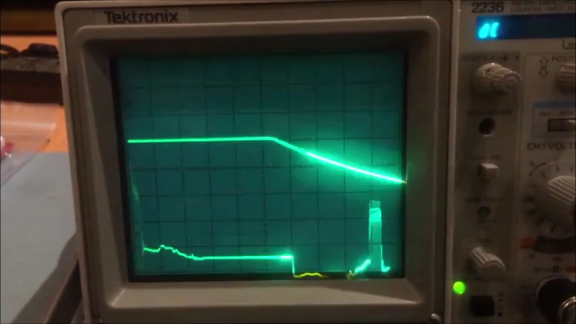
I did some poking around in the Arduinio Uno schematic and determined there was a 47μF capacitor on the output of the +5V voltage regulator, and so I thought I might be able to trigger off power loss at the input to the regulator and accomplish the writes while the capacitor was still holding up the Arduino processor. I put a 1/3:2/3 voltage divider on the +12V input line and used my trusty Tektronix 2236 scope to monitor it and the +5V regulated output. With the scope I was able to see that the +5V output stayed up for about 5msec, and stayed above 4V for 8msec, as shown in the following scope photo.
Scope photo of Arduino Uno +5V regulated output, triggered by removal of +12V input power. Time scale 1msec/div.
The next step was to modify Adafruit’s FRAM read/write example program to implement a power-down interrupt routine to test my idea. Here’s the code (the software is also available here)
1
2
3
4
5
6
7
8
9
10
11
12
13
14
15
16
17
18
19
20
21
22
23
24
25
26
27
28
29
30
31
32
33
34
35
36
37
38
39
40
41
42
43
44
45
46
47
48
49
50
51
52
53
54
55
56
57
58
59
60
61
62
63
64
65
66
67
68
69
70
71
72
73
74
75
76
77
78
79
80
81
82
83
84
85
86
87
88
89
90
91
92
93
94
95
96
97
98
99
100
101
102
103
104
105
106
107
108
109
110
111
112
113
114
115
116
117
118
119
120
121
122
123
124
125
126
127
128
129
130
131
132
133
134
135
136
137
138
139
140
141
142
143
144
145
146
147
148
149
150
151
152
153
154
155
156
157
158
#include <Wire.h>
#include "MyAdafruit_FRAM_I2C.h"
/* Example code for the Adafruit I2C FRAM breakout */
/* Connect SCL to analog 5
Connect SDA to analog 4
Connect VDD to 5.0V DC
Connect GROUND to common ground */
MyAdafruit_FRAM_I2C fram=MyAdafruit_FRAM_I2C();
uint16_t framAddr=0;
volatile uint8_t testval;
constintInterruptPin=2;
constintRestartCountAddr=0x0;
volatile bytestate=LOW;
bytelast_state=state;
constbyteledPin=13;
constintCLEAR_FRAM_PIN=3;
constintNUM_LOCS_TO_CLEAR=100;
intnextFramWriteAddr=2;//addr 0 reserved for restart count, addr 1 is unusable (don't know why)
constintNUM_TIMES_TO_DISPLAY=10;
boolInSetup=true;
voidsetup(void)
{
Serial.begin(2000000);
if(fram.begin()){// you can stick the new i2c addr in here, e.g. begin(0x51);
Serial.println("Found I2C FRAM");
}
else{
Serial.println("I2C FRAM not identified ... check your connections?\r\n");
Serial.println("Will continue in case this processor doesn't support repeated start\r\n");
noInterrupts();//turn off interrupts so we can't be interrupted while resetting our special variable
IsRunning=false;
}
The above code takes advantage of a modified version of Adafruit’s I2C FRAM library that facilitates writing and reading of arbitrary data types like int, long, float, etc. The modifications were cribbed from Nick Gammon’s wonderful ‘IC2_Anything’ library – thanks Nick!
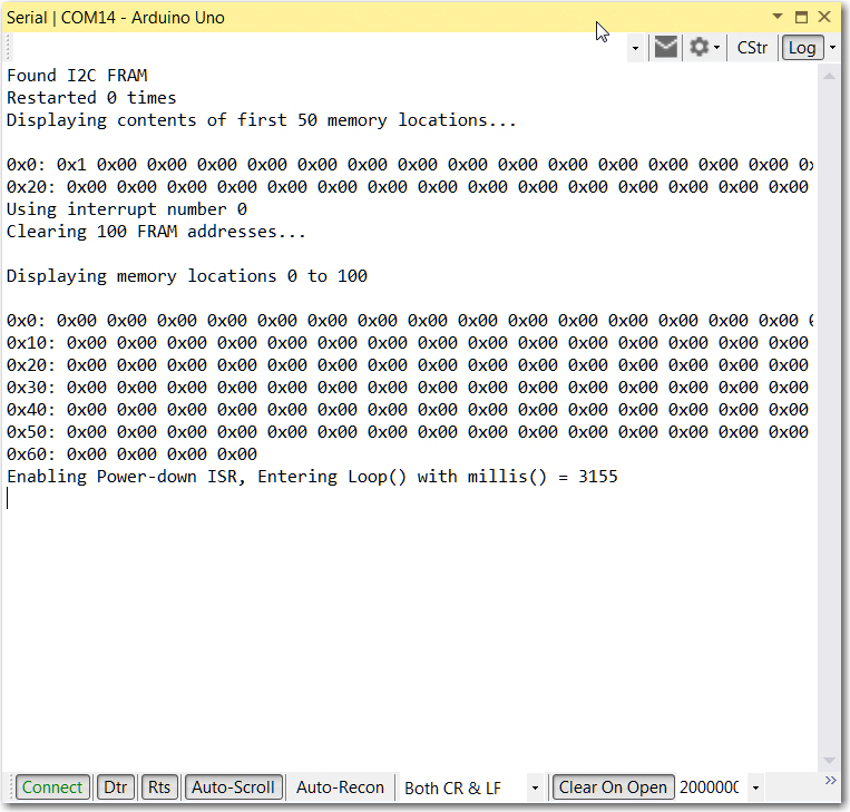
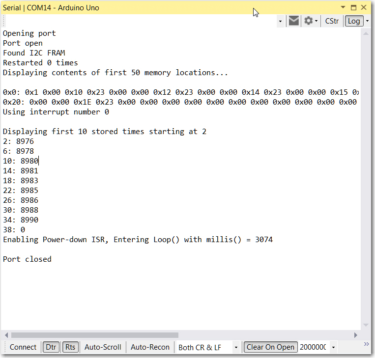
With this test setup, I was able to repeatedly clear the FRAM memory and see the effect of pulling the power plug. A typical result is shown below:
Program response when restarted with CLEAR_FRAM_PIN (pin 3) grounded
Program response after the power plug was pulled at about 8.9 sec after startup.
In the first figure above, the CLEAR_FRAM_PIN (pin 3) was held LOW while the Arduino was restarted, resulting in zeroes being written to the first 100 FRAM locations. In the second figure, the +12V power plug was pulled after about 9 seconds, then reconnected. When the Arduino restarted, the power-down ISR had written program timer values from 8976 to 8990 into the first nine 4-byte segments. This shows that the Arduino continued to operate for about 14msec after the power plug was removed. This is very good news, as it implies that I should be able to write the current date/time value from a real-time clock (when I get it running, that is) into FRAM whenever there is a power interruption, allowing me to accurately track battery usage history.
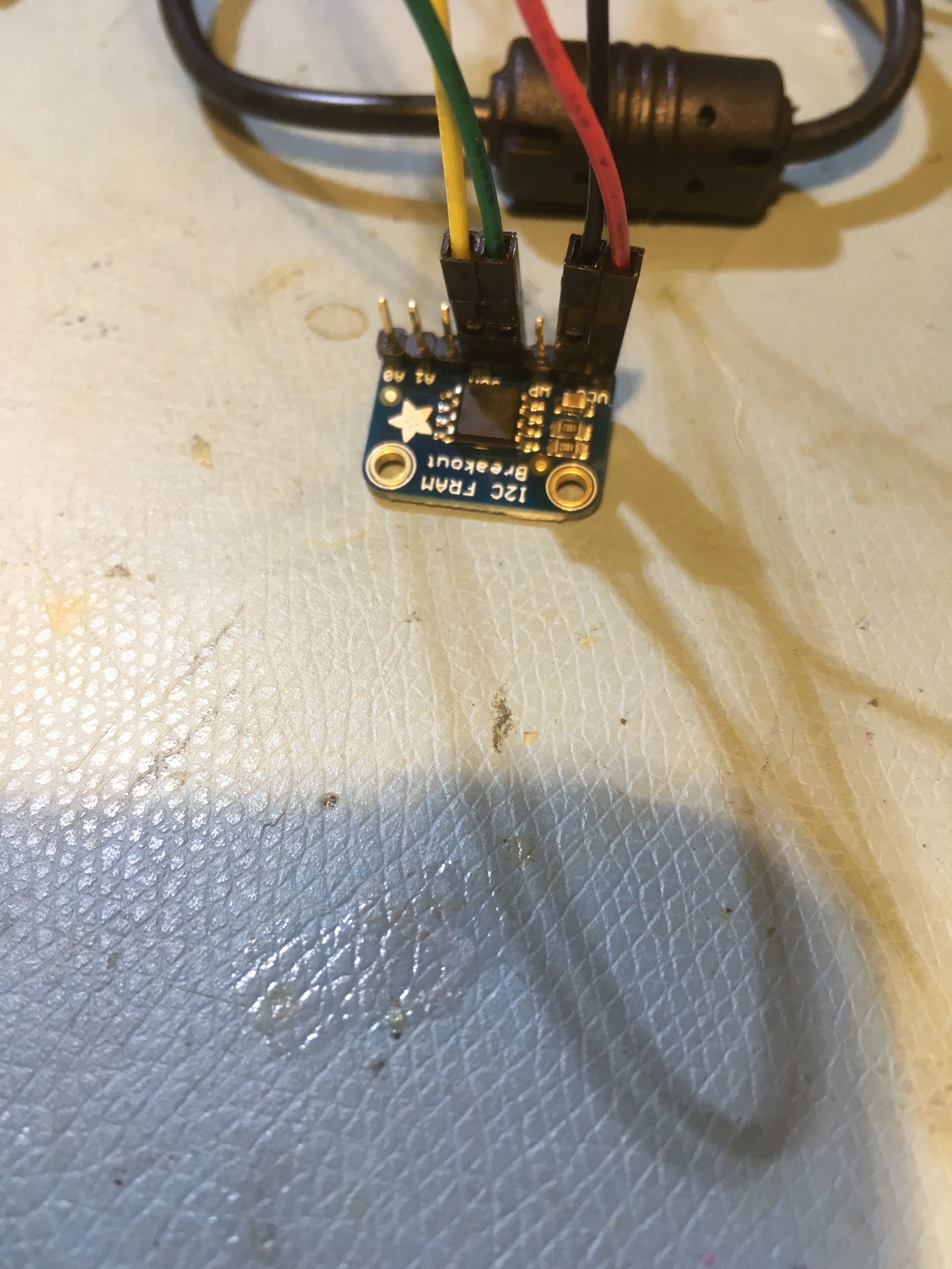
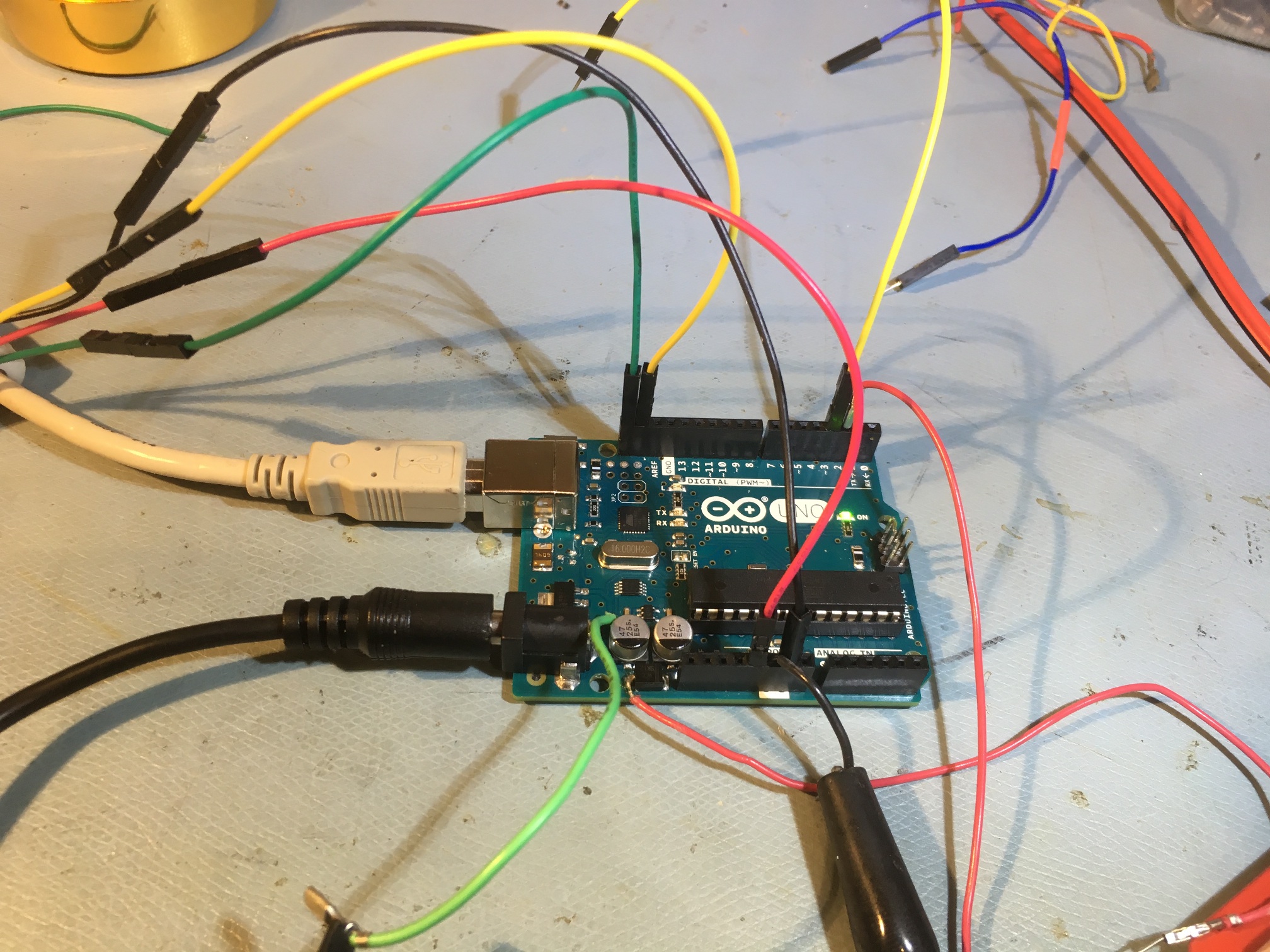
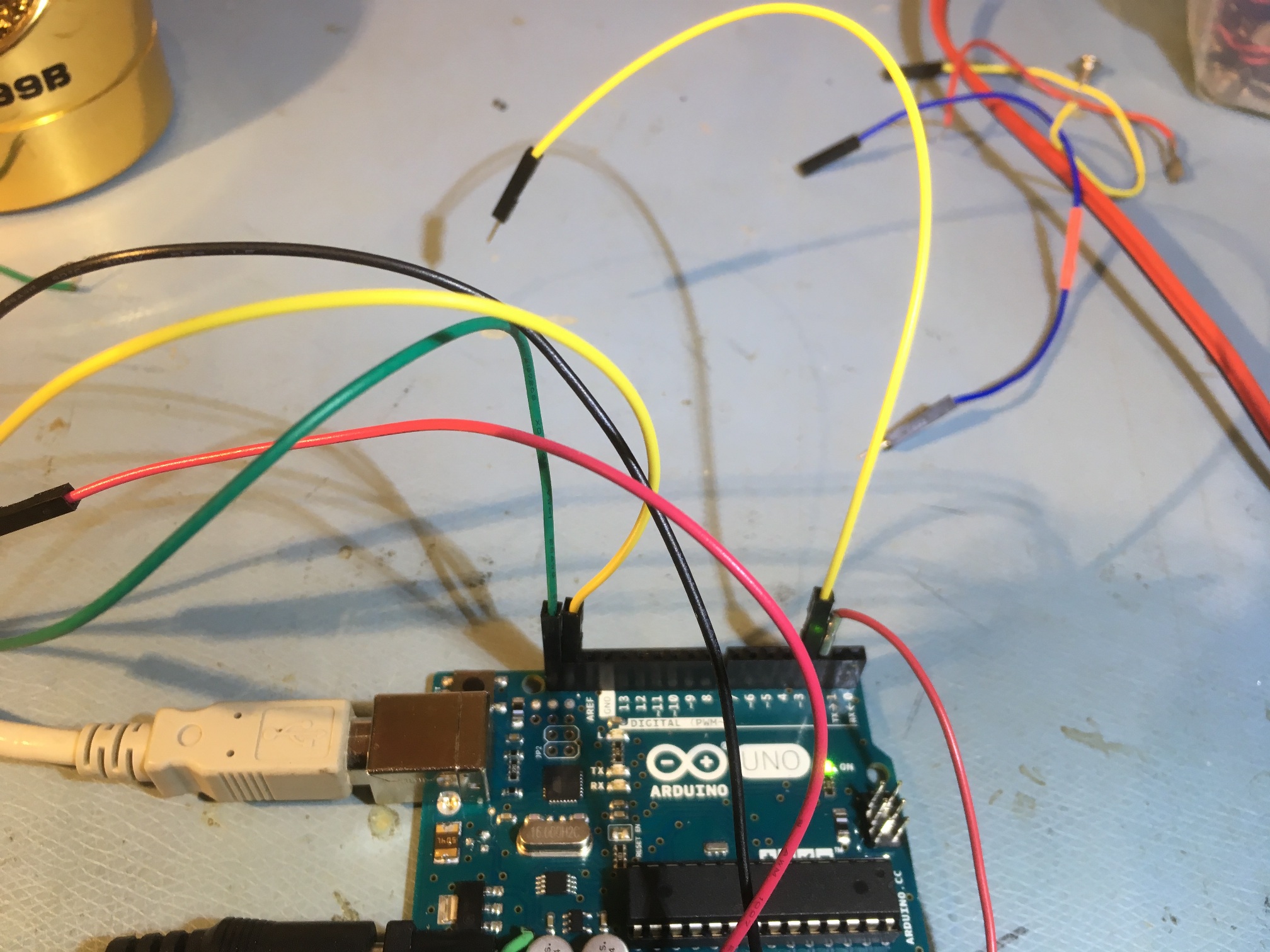
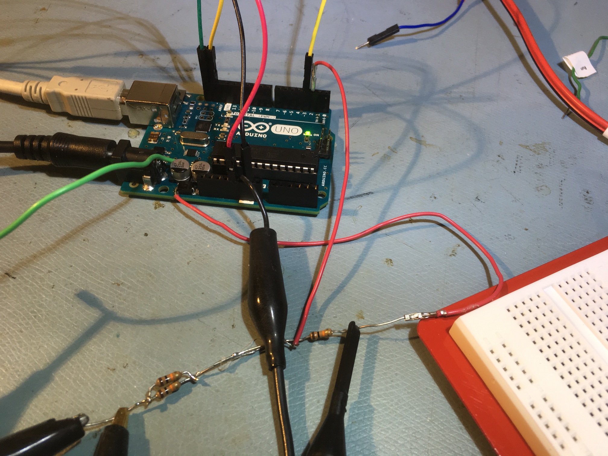
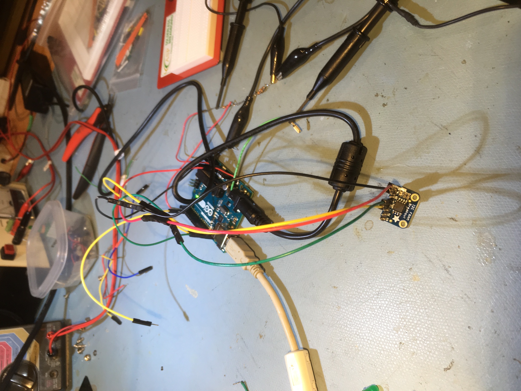
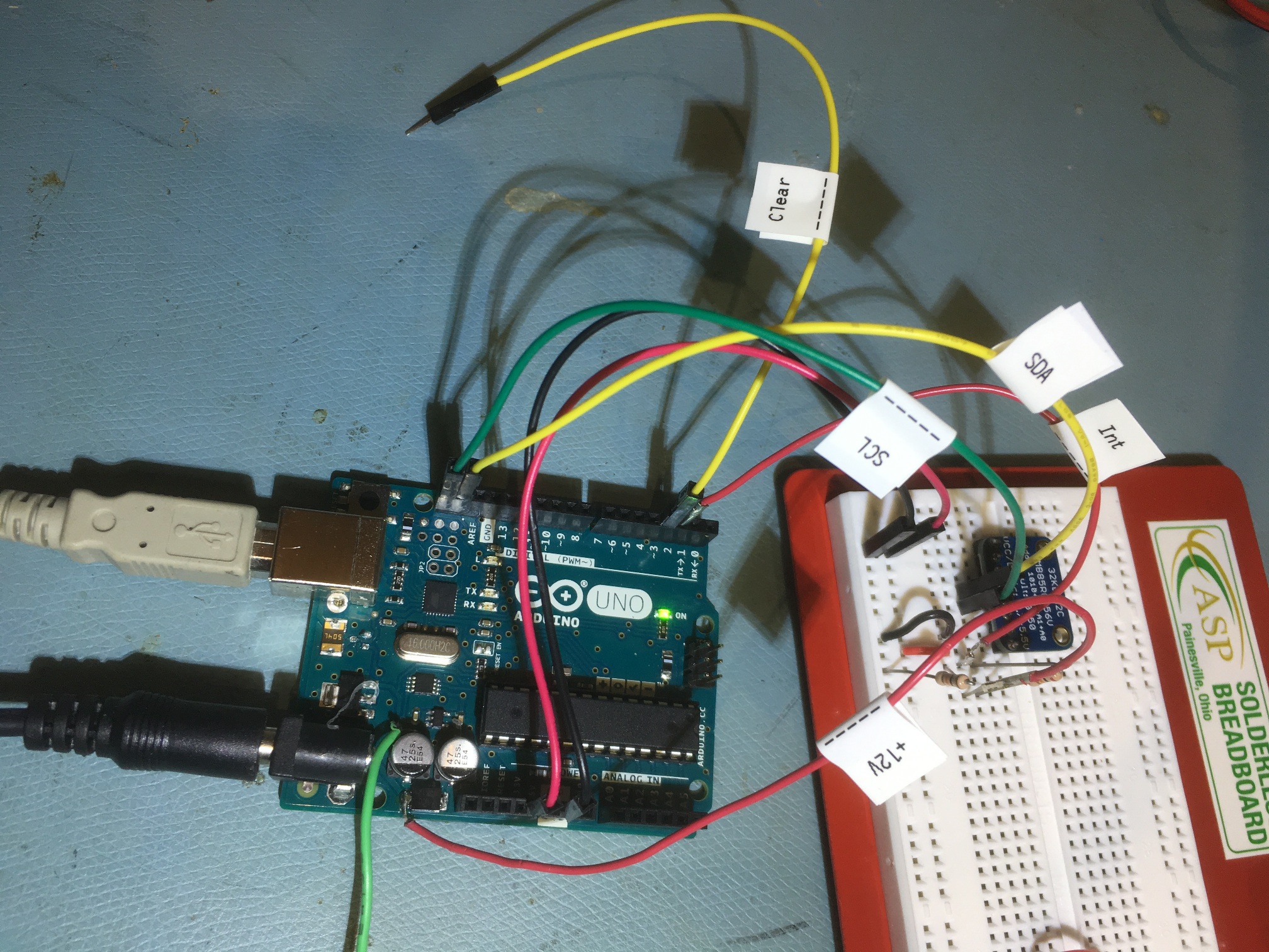
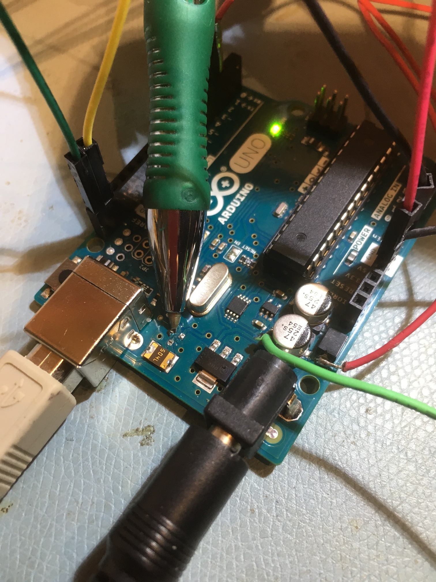
The hardware used to perform these tests is shown in the following photos:
Experimental setup moved to new ASP solderless breadboard
Arduino Board Modification:
I ran into a problem when I started testing the power-down interrupt idea; I wanted to keep thE Arduino board connected to my PC via the USB cable, but if I did that, the Arduino would automatically switch over to USB power when I disconnected the +12V power cable. Fortunately, if you have a problem, it’s almost certain that someone else has had and solved the same problem. In my case I found this post, that explained that T1, the automatic power crossover MOSFET switch had to be removed, as shown in the following photo. This modification allows the USB cable to continue to supply USBVCC power to U3, the ATMEGA8U2-MU chip, which in turn allows the PC to recognize the Arduino for firmware uploads.
So, now that I have demonstrated the practicality of a power-down interrupt routine to capture time-of-shutdown information (at least on an Arduino Uno), the next step is to integrate this capability with the Adafruit RS3231 Precision RTC breakout board. Stay tuned!
09 April Update: Adafruit DS3231 RTC breakout board added:
As I mentioned in my ‘Time and Memory for Wall-E2‘ post, I planned to complement the FRAM capability with the addition of an RTC module so that I could record the time & date of any power interruptions. As I mentioned in that post, I planned to use the Adafruit DS3231 Breakout Board for this purpose. After receiving the module, I added it to the system by daisy-chaining the I2C SCL & SDA lines from the FRAM module, and modified the software to incorporate the RTC. I changed the FRAM_ISR() function to acquire ‘Unixtime’ from the RTC (i.e. the number of seconds since 00:00:00 UTC on January 1, 1970) and write it to the FRAM.
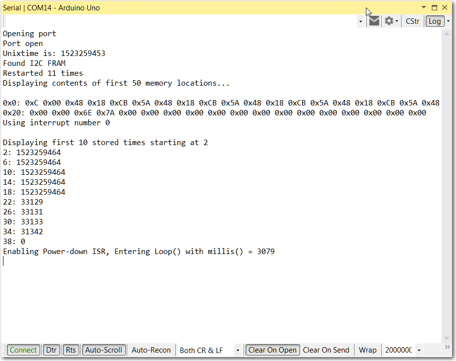
I tested this by uploading this firmware to the Arduino Uno, and then pulling the power plug a few seconds after the program entered the main loop. Here’s the printout from the run
Program run with Adafruit DS3231 RTC added. Note ‘unixtime’ printout at top, and first 5 FRAM locations at bottom
As can be seen from the above printout, the power-down ISR successfully recorded the current time (in ‘Unixtime’ format) into five successive FRAM memory locations before the Arduino died. Note also that the recorded time was eleven seconds after the time shown at the top of the printout – about right, as the upper value is the time retrieved using the PC’s __DATE__ and ___TIME___ environment variables at the time the program was compiled and uploaded to the Arduino board.
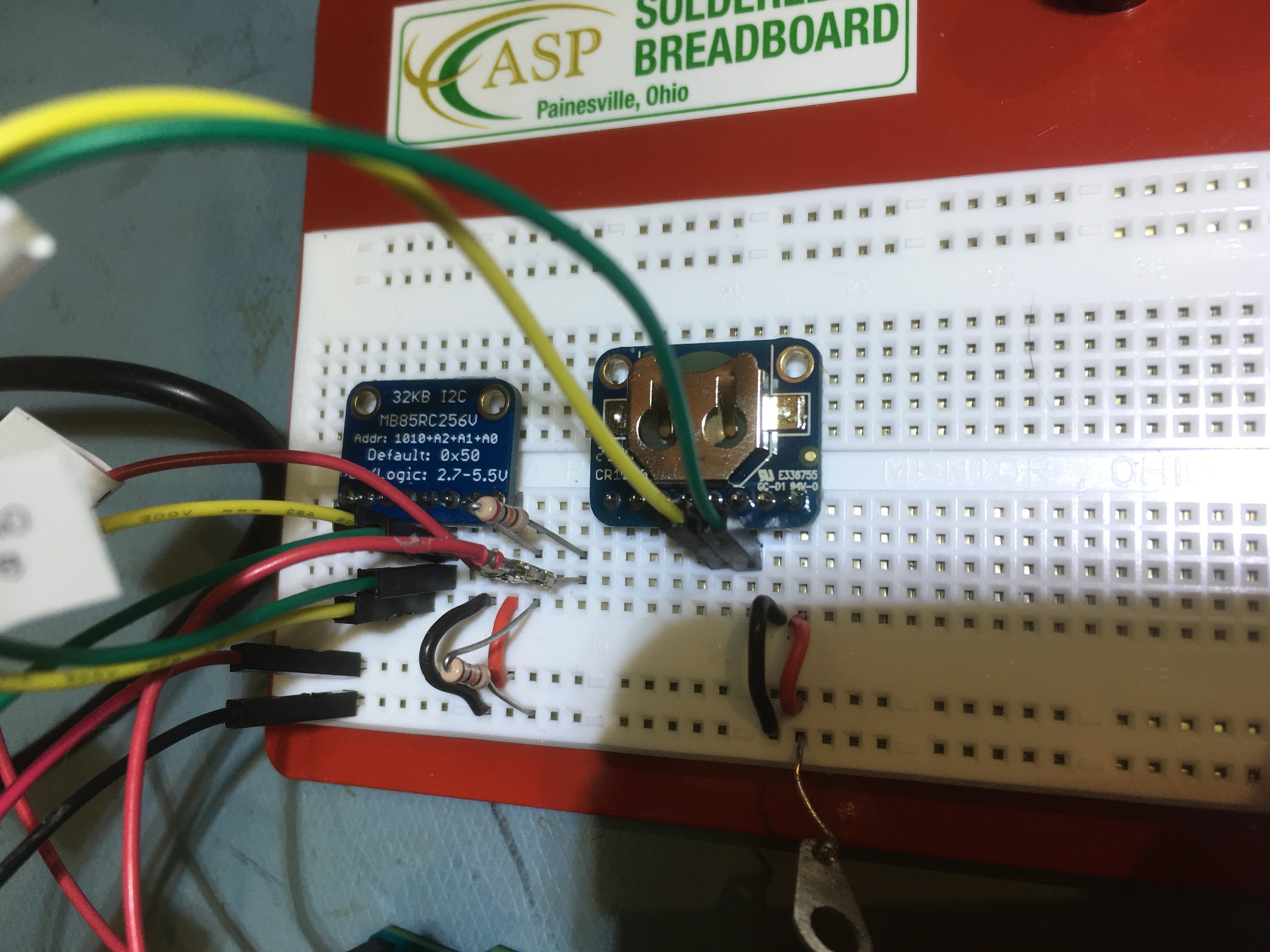
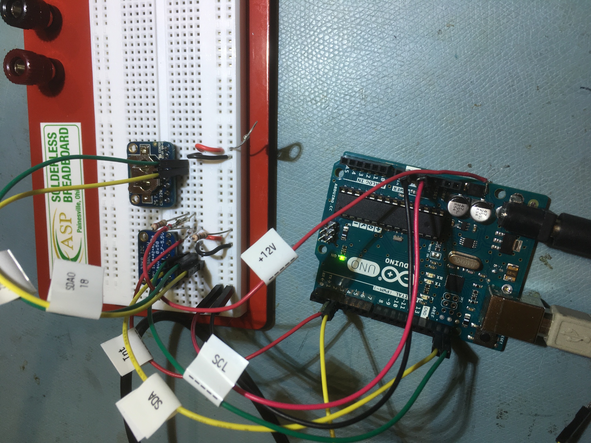
Here are some photos of the new hardware setup:
Adafruit FRAM module on the left, DS3231 RTC module on the right
Now that I have Wall-E2’s charging module and charging station working, I’ve moved on to some secondary, but still important, issues that need addressing.
Wall-E2 still can’t tell which way he is heading. This isn’t necessarily a killer, as his current technique of simply following walls does fairly well. However, when it comes to a human figuring out where Wall-E2 is or has been, distance to the nearest wall just doesn’t cut it. A while ago I attempted to solve this problem using an onboard magnetometer, but ultimately concluded a magnetometer-based navigation system is doomed to failure in an indoor environment, due to too many interfering magnetic signals. I have decided to try this again, but this time using a cheap solid-state gyroscope module from Sparkfun. I should be able to initialize the gyroscope z-axis to an absolute heading each time Wall-E2 connects to a charging station, as their location(s) and headings are known. As a bonus, I should be able to use the gyro to generate accurate 90 º turns, instead of the current open-loop timing method.
Wall-E2 remembers how long it has been since its last recharge, but only if the main power hasn’t been interrupted. If I turn him off for any reason, that information goes away. I dicked around with writing the current value of millis() to EEPROM on power-down, but it turns out that EEPROM writes are way too slow for that. After Googling around for a bit, I found a nice little FRAM (Ferro-magnetic Random Access Memory) module from Adafruit, and I believe I will be able to implement a power-down memory save feature using it.
Once I have a fast non-volatile FRAM solution, it occurs to me that I may want to write telemetry information to it, so it isn’t lost when Wall-E2 is out of range of the current Wixel link to my PC. Maybe even set the FRAM (or at least part of it) up as a rate buffer between Wall-E2 and the Wixel. The idea would be that telemetry data always goes to the FRAM at some rate A, and is then read from the FRAM to my PC via the Wixel link at rate B, where B > A. When the link isn’t available, the telemetry data continues to be written into the FRAM, and is read back out again when the link becomes available. As long as the link isn’t interrupted for too long, I won’t lose any telemetry data. As part of this implementation, I would like to time-stamp the data with real date-time information, which requires a battery-backed RTC (real-time clock). As it happens, Adafruit has one of these too, so I may be able to implement it quickly and easily.
I chose the I2C versions of all these modules, as I already have I2C implemented for acquiring steering cues from my IR Homing Module. In theory, at least, adding three more I2C slave devices to an already existing setup should be trivial.
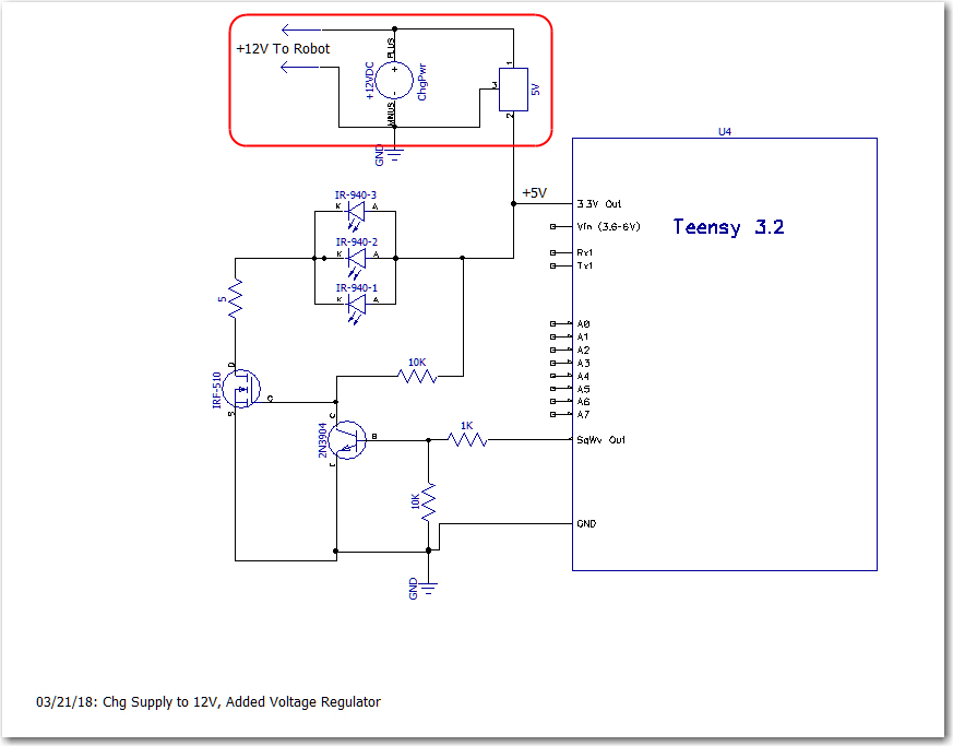
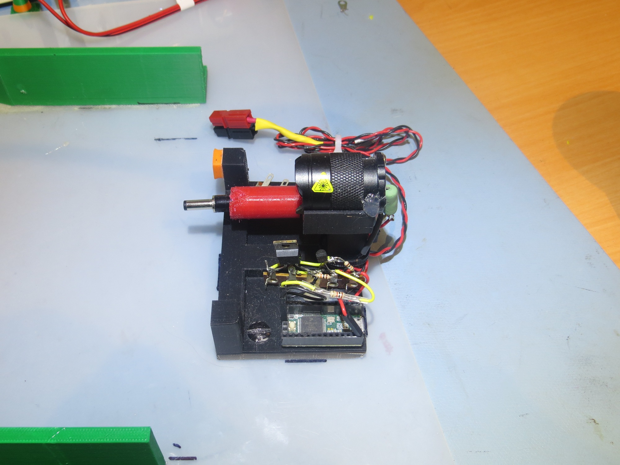
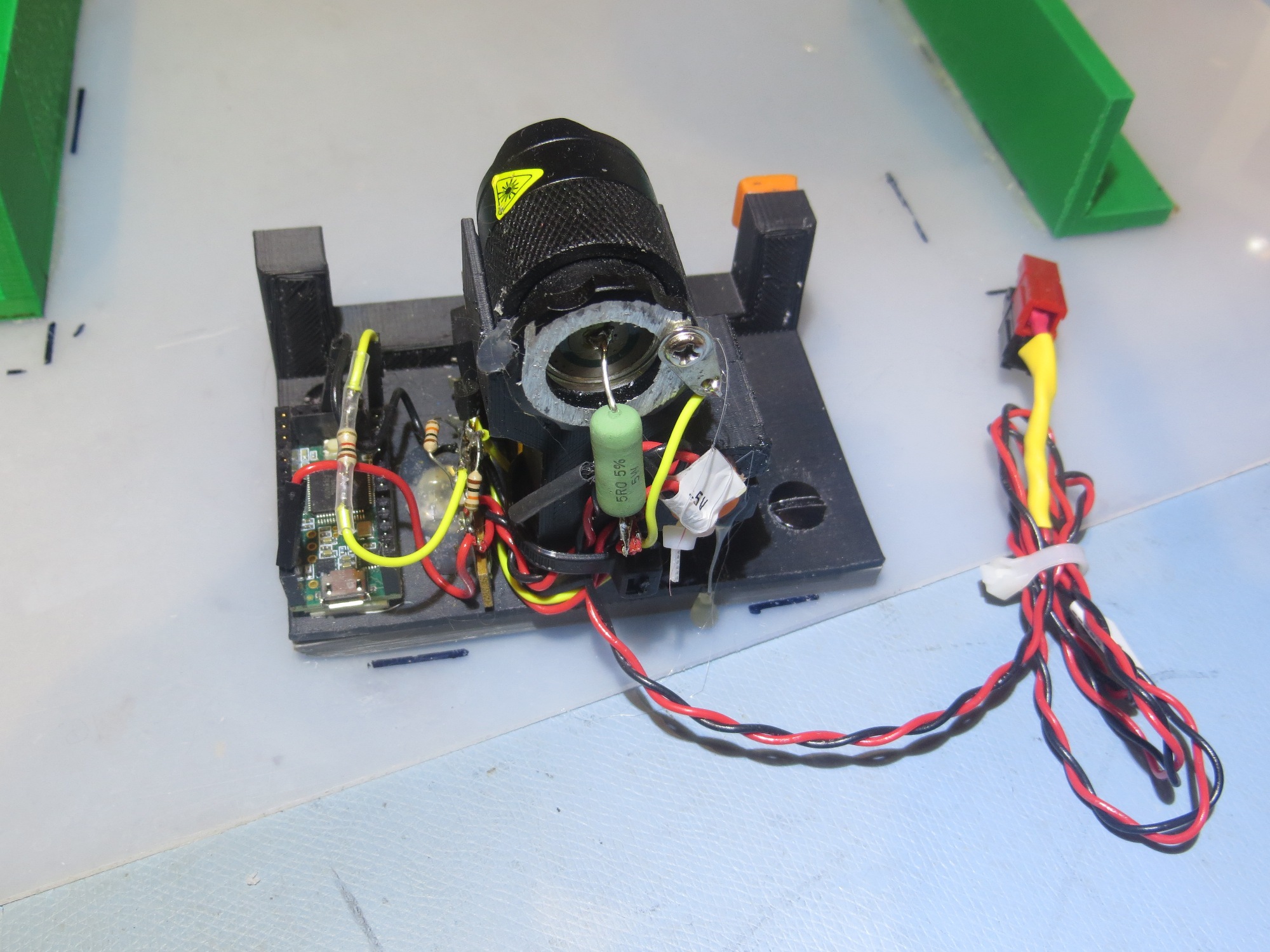
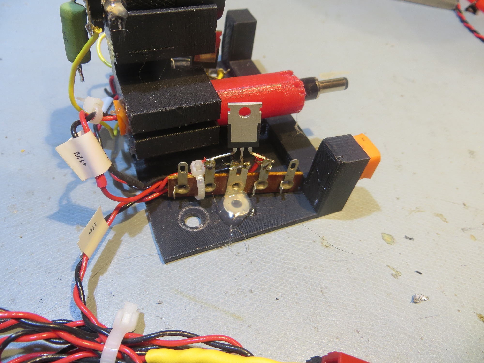
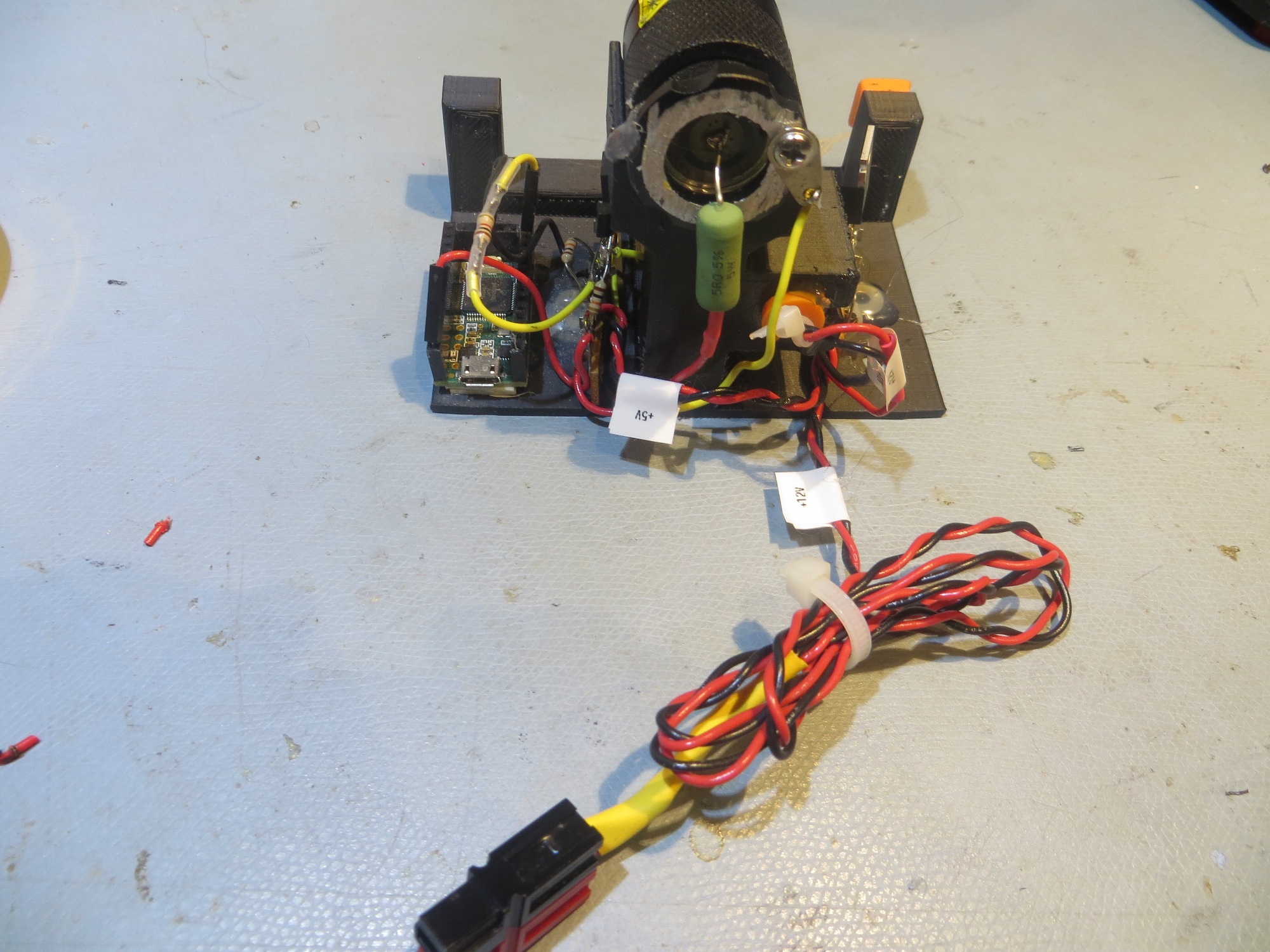
With the replacement of my Power Boost 1000C – based charger module with the TP5100, I needed to change the charging station supply voltage from +5V to +12V. Unfortunately, the modulated IR beam signal is generated by a Teensy 3.2 module, which requires +5V (it’s actually a 3.3V module, but can accept power of up to +5V), so now I needed both +5 and +12V on the charging station. The answer was to add a simple 3-pin regulator, as shown in the schematic below
Updated charging station schematic showing addition of a 3-pin 12-to-5V regulator
The original Teensy 3.2 side
The original 5V charging station layout, rear view
I think it is important that Wall-E2 have an accurate measurement of battery voltage, so that he knows when he should be looking for his next charging fix, and more importantly, so he can stop and yell for help if the battery voltage gets dangerously low. In addition, I would like to monitor the battery voltage during charge, so Wall-E2 can report & display charging progress to any interested humans (like me). ;-).
From what I’ve read, it appears a LiPo cell can go down to about 3V without damage, or 6V for my 2-cell stack. So, my operating voltage range is from full charge (approx 8.4V) to empty (6.0V). My first cut at battery voltage monitoring was a simple 1/3 – 2/3 resistive voltage divider tied to an analog input; simply measure the voltage, multiply by 3, and voila – battery voltage!
Only it didn’t work that way; once the battery voltage dropped below about 7V, the drop across the Arduino Mega’s voltage regulator wasn’t sufficient to maintain regulated 5V, so the Mega’s bus voltage began to drop. At Vbatt = 6V, the Mega was still running OK, but the bus voltage was down to 4V, and the A/D reference was no longer what it should be – rats!
In addition, once I started looking at this issue, I realized I was throwing away most of the A/D dynamic range with the divider idea. with a 5V A/D reference and a 1/3 divider, the A/D input voltage only varies between 2.0 and 2.8V for an input range between 6 and 8.4V. In other words, I’m only using 0.8V of the available 5V range or about 16%.
So, I thought that maybe I should implement a level shifter, so the sensed voltage varies from 0 to 2.4 as the battery voltage varies from 6 to 8.4 – and then use the Mega’s internal 2.56V reference for the A/D operation. This would mean an immediate increase in dynamic range usage from 16% to almost 94%, and would increase resolution from about 15mV/count to about 2.5mv/count. To do the level shifting, I’ll need a 6V zener, such as the 1N5233B, available from Mouser for a few pennies each.
One last voltage issue to be addressed is the problem with the Mega’s onboard regulator dropping out for battery voltages between 7 and 6V – this is almost half of the available voltage range. Eventually I decided to address this problem by replacing (or rather, bypassing) the onboard regulator with a low dropout (LDO) regulator such as the LF50CV-DG , available from Mouser for less than $1 each. The LF50CV-DG can maintain 5V output down to well below my 6V battery voltage cutoff limit, so it is a good match.
23 March 2018 Update:
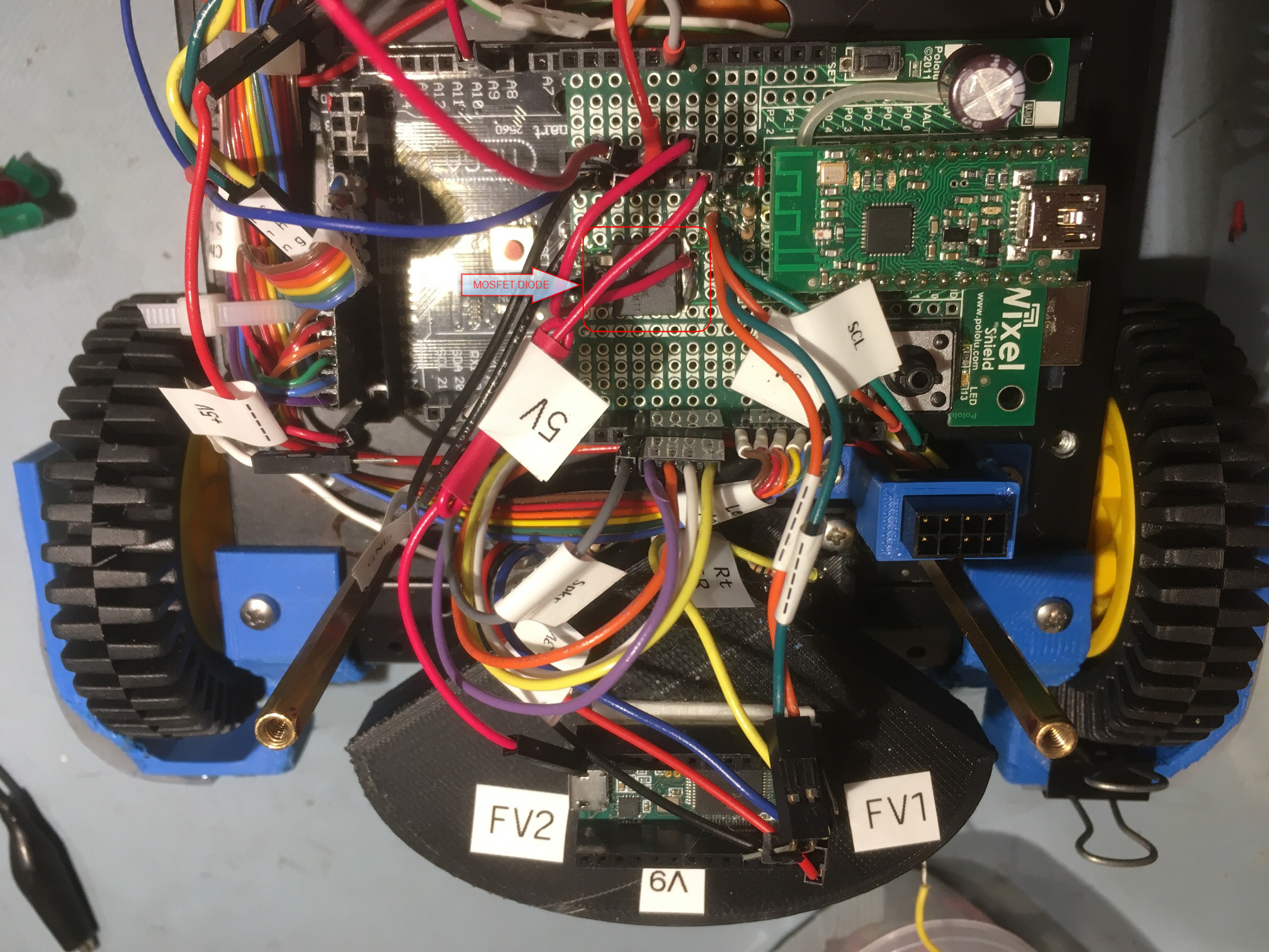
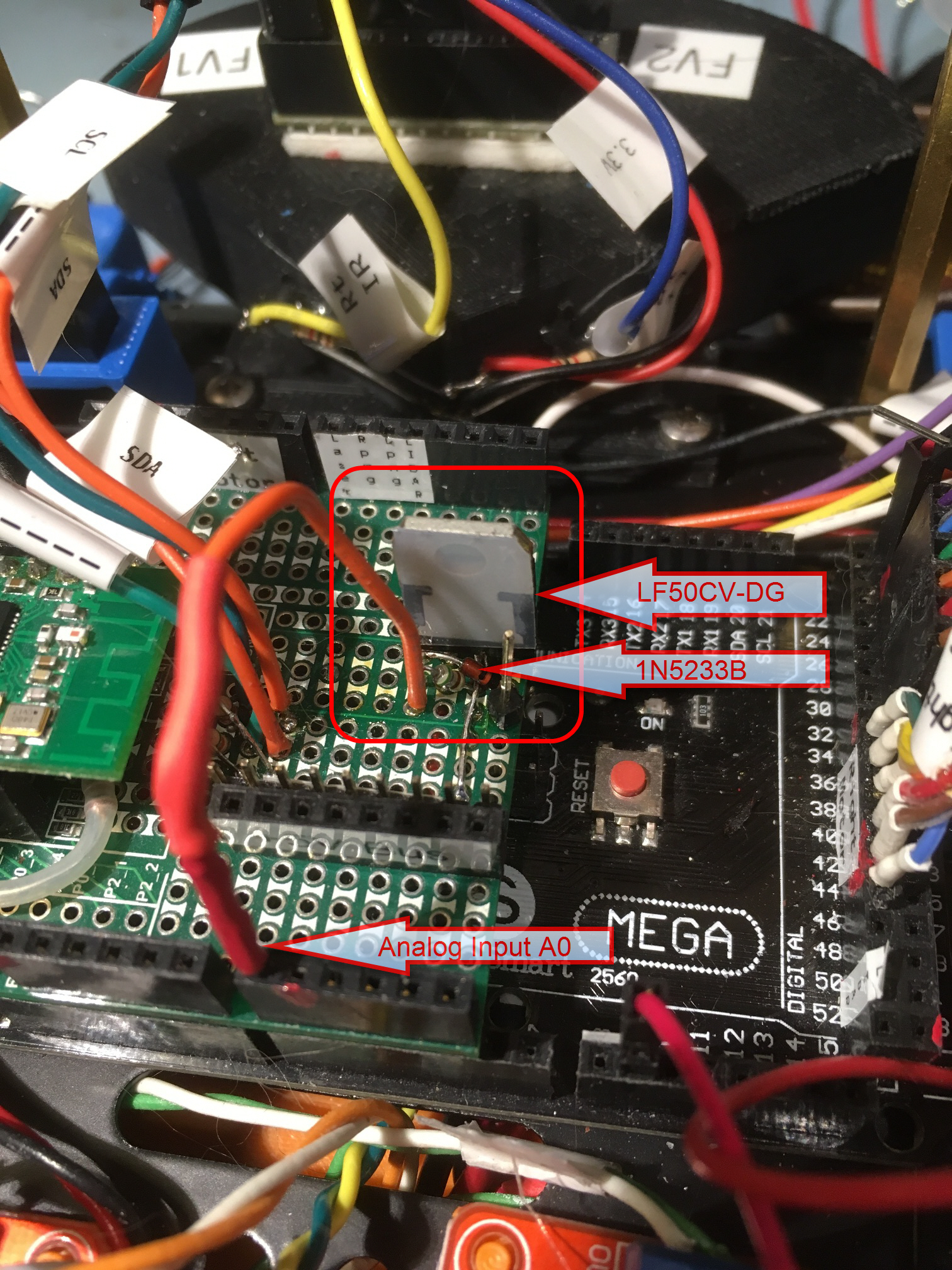
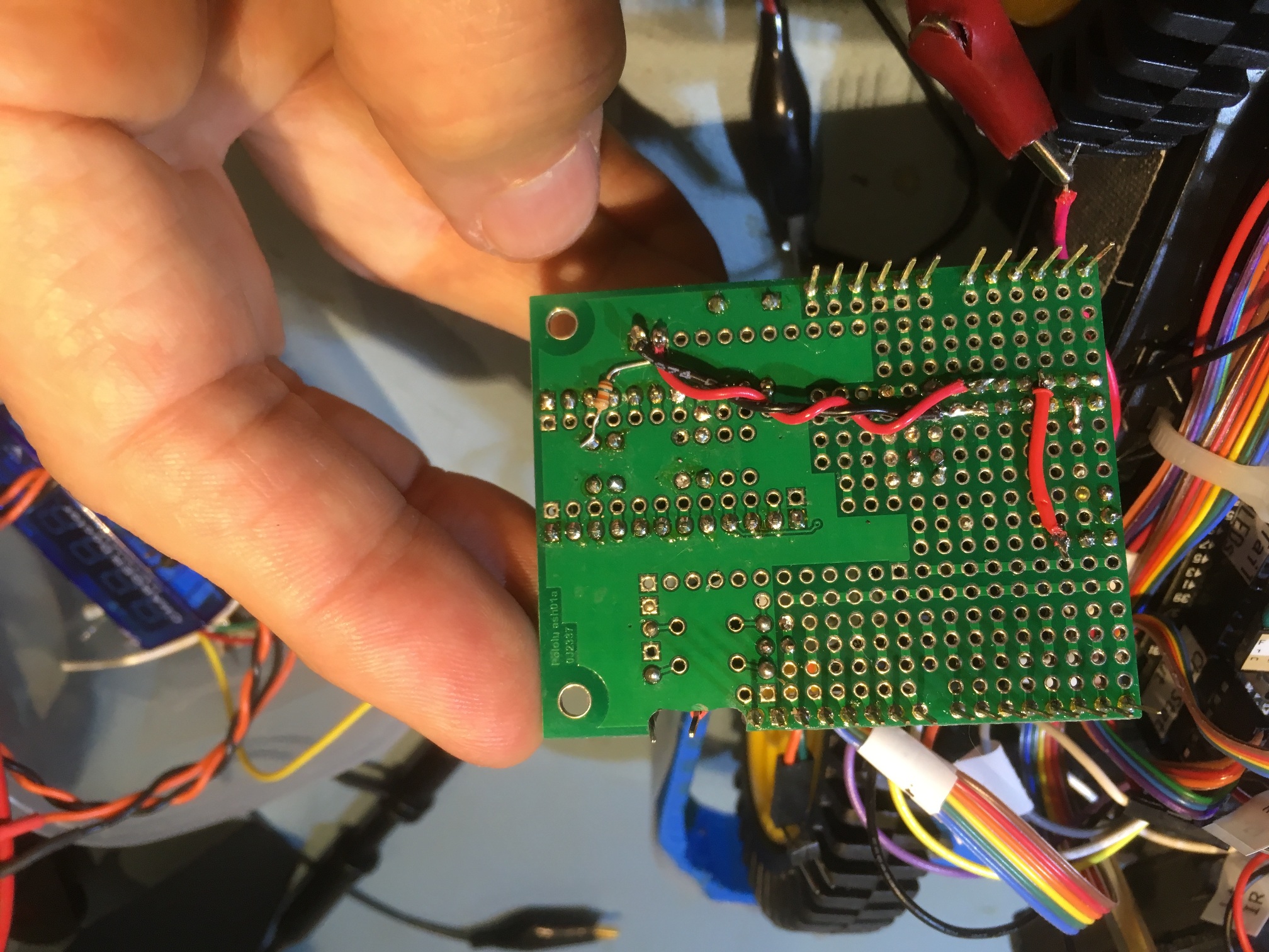
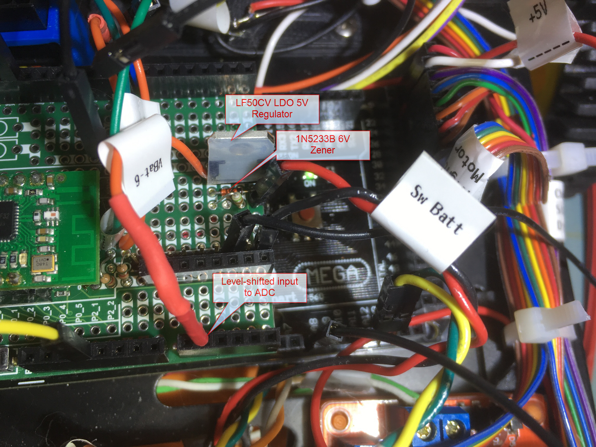
I just received the LF50CV-DG regulator and 1N5233B parts from Mouser, so I’m in the process of installing them onto Wall-E2. The regulator will take the place of the MOSFET low-drop diode I installed on the Pololu Wixel Shield some time ago as part of my old PB1000C-based charging subsystem, and is now no longer needed. The following photos show the installation:
Wixel shield showing MOSFET diode to be replaced by LDO 5V regulator
LF50CV-DG LDO 5V regulator and 1N5233B 6V Zener diode installed on Wixel shield
Rear of Wixel shield showing regulator output connection to +5V bus
25 March Update:
While testing the above arrangement, I managed to somehow kill my Mega 2560 SBC (I think my old power supply did it in, but I’m not sure). So, in the process of recovering from this mess, I also decided to replace my old Wixel shield for the latest version (v1.1) with updated level-shifting circuits and carry-throughs for the added pins on the UNO R3, Mega, and cousins. The new layout is shown below
Updated Wixel shield board with LDO 5V regulator and level-shifter circuit installed
Once I got everything back together, I started over with testing the LDO 5V regulator and level shifter performance, and ran into another problem. The original idea was to use the 1N5233B 6V zener to level shift 6-8.4V to 0-2.4V so the range would fit into the range obtainable using the Mega’s internal 2.56V ADC reference. This worked almost perfectly, but the combination of a slightly lower Vz (5.84 vs 6.00V) and a slightly lower Vref (2.42 vs 2.56V) caused the ADC to hit full scale (1023 counts) at about 8.26V (2.44Vref + 5.84Vz = 8.26V). Most unfortunate, as I really needed to accurately measure Vbatt to at least 8.4V, nominal end-of-charge voltage for a 2-cell LiPo stack.
So, I needed to expand the measurable voltage range at least a little bit on the top end. With the installation of the LF50CV LDO 5V regulator, I could now do that by reverting to the internal 5V reference, as the LDO easily maintains 5V output all the way down to 6V, the cutoff voltage for my battery stack. But, this wastes half the available ADC range, as the ADC input voltage for Vbatt = 8.4 is only 8.4-5.84 = 2.56V. So, after some more Googling through Arduino-space, I realized I could tie the Mega’s AREF pin to the Mega’s 3.3V output line and use ‘analogReference(EXTERNAL)’ to obtain an ADC range from 0-3.3V, corresponding to a Vbatt range of 0 to (5.84+3.3)= 9.14V – perfect!
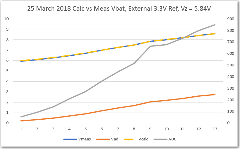
After making this change I ran some measurements to verify the input range and accuracy, as displayed in the following Excel plot
Measured vs Calculated Vbatt, with raw ADC values
As can be seen in the above plot, the measured and calculated voltage plots are almost perfectly overlaid, and well within the accuracy requirements for effective battery management.
Summary:
As usual, what started out as a simple plan (in this case, to accurately measure the battery voltage) rapidly metastasized into a full-blown hardware and software project, complete with howls of anguish and gnashing of teeth. The first idea was to use a simple 1/3 resistive voltage divider input to a ADC port referenced to 5V. This worked OK, but failed at battery voltages below 7V because the Mega’s onboard voltage regulator requires an approximately 2V input-output offset. Since I needed to measure Vbatt down to 6V, this was never going to work. In addition, the available measurement accuracy sucked because the 2.5V range of interest was being compressed into 2.5/3 = 0.833V, and with a 5V reference I was using less than 20% of the available ADC counts. The next idea was to replace the onboard regulator with the LF50CV LDO regulator, and use a 6V zener to level shift the range of interest to under 2.56V so that the Mega’s internal 2.56V reference could be used. This almost worked, but I ran out of ADC counts before I ran out of battery voltage – oops. The third (and last, I hope) idea was to change the ADC reference from internal 2.56V to external 3.3V using the AREF pin tied to the Mega’s 3.3V regulated output. This allowed the top voltage to go to a little over 9V, just about perfect for this application.
To paraphrase the saying, “to a man with a hammer, every problem looks like a nail”, “to a man with a 3D printer, every problem looks like a 3D printing opportunity”. And that’s pretty much what happened when I ran across the problem of adapting some 80mm wheels to my Wall E-2 robot, which came originally with 65mm versions. The extra 15mm diameter/7.5mm radius doesn’t sound like much, but it makes a huge difference when navigating over carpet or other small obstacles (like my wife’s slippers).
After a lot of work, I finally was able to print four reasonable quality adaptors, and thought I was home free. Unfortunately, I soon learned that despite my best efforts, the printed adaptors were no match for physics; the wheel eventually worked its way off the motor shaft, just as before – it just took a little longer ;-).
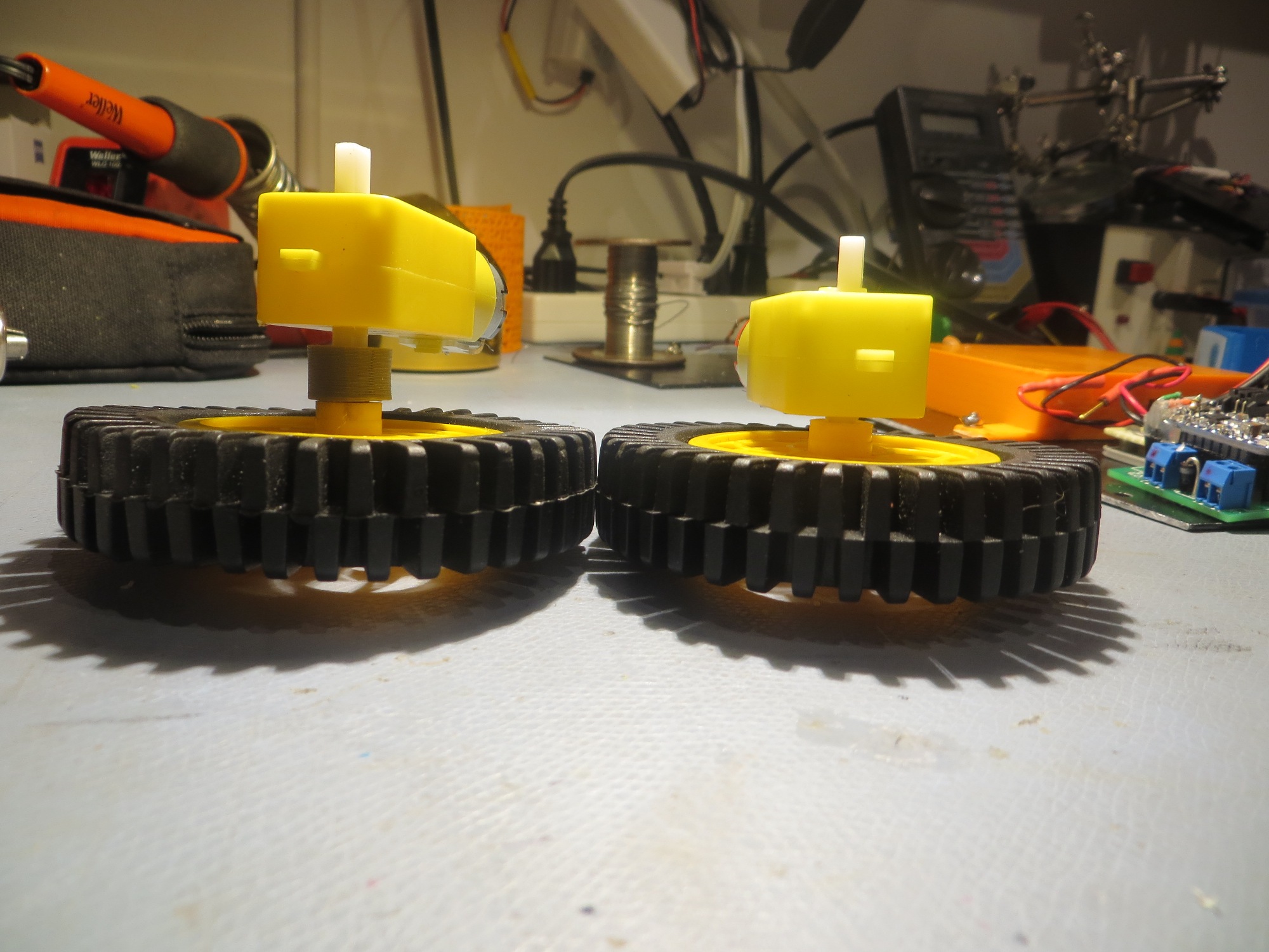
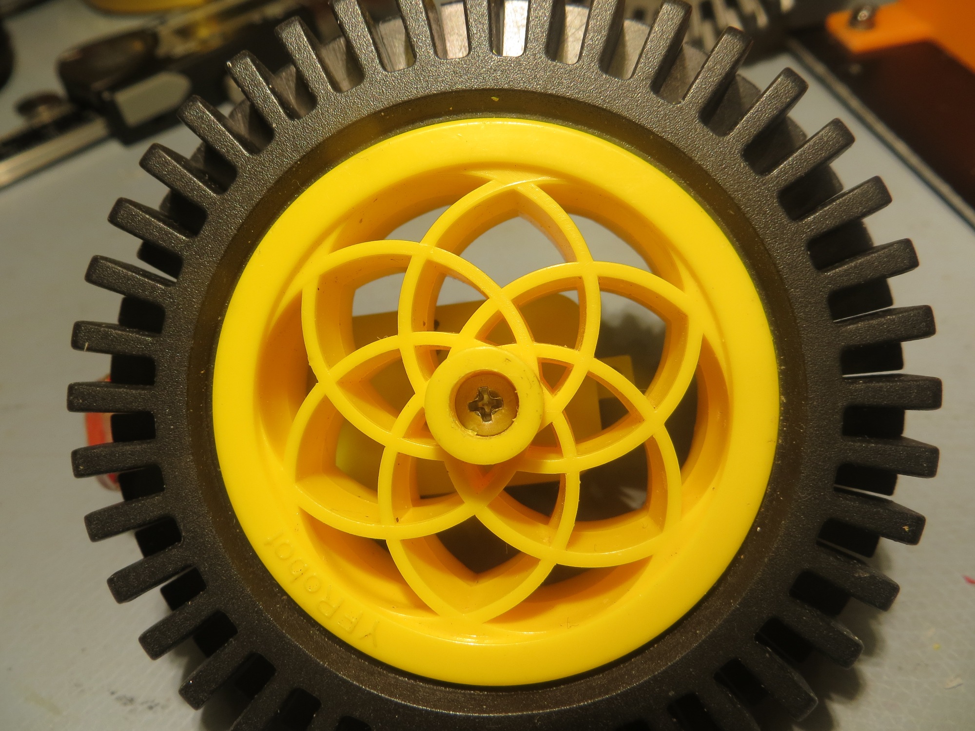
After the usual number of curses, imprecations, and woe-is-me’s, I finally decided to use whatever was left of my engineering brain to actually look at the physics of the situation. When I did so, I realized that my adaptor idea was never going to work. While the adaptor did indeed (after the aforementioned ‘lot of work’) provide for a better fit between the 80mm wheel receptacle and the motor shaft, it also moved the wheel another 9mm or so away from the robot chassis, which put the wheel center of pressure (CP) well outside the adaptor-to-motor shaft parting plane. This meant that the wheel would always be trying to pry the the adaptor off the shaft, and it didn’t take all that long for it to succeed :-(. The following photo illustrates the problem
80mm wheel with 3D-printed adaptor on the left, same wheel directly attached to motor shaft on the right
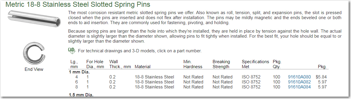
So, contemplating this problem while drifting off to sleep I was struck by a solution; I could use a small roll pin inserted through the wheel and motor shafts to literally pin them together. The geometrical physics would still cause the wheel to flex the shaft, but the forces wouldn’t be able to overcome the strength of the metal roll pin. Because I knew I would forget this insight if I left it until morning, I staggered out of bed and jumped onto the McMaster-Carr site (they have everything!) to look for an appropriately sized roll pin. I found a 1 x 6mm roll pin that would be perfect for the job, and if I ordered them now they would probably already be on my doorstep when I woke up in the morning.
McMaster-Carr metric roll pins
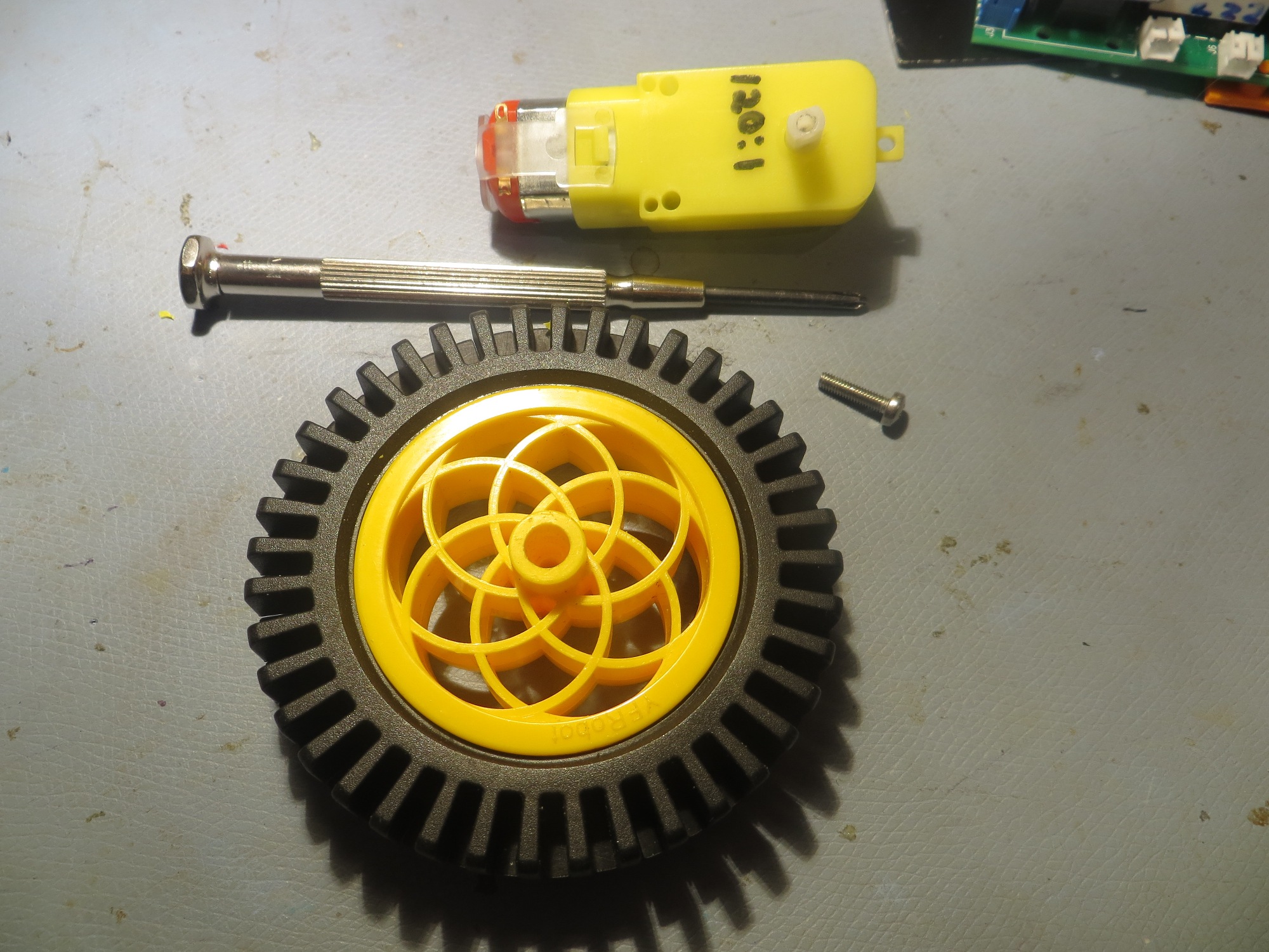
However, while I was doing the necessary measurements on the motor shaft, I noticed the motor shaft had a axial hole in it, and so did the wheel; hmm, maybe I could simply run the roll pin through the axial hole, instead of cross-wise? Then I thought – wait that hole looks to be slightly smaller than 3mm – maybe I could simply drill/tap it for 3mm and use a 3mm screw (of which I had plenty in different lengths) instead of a roll pin?
So, in just a few minutes I had drilled & tapped the axial hole in the motor shaft of one of my spare motors, drilled out the wheel hole for 3mm clearance, and firmly screwed the wheel to the shaft (the right-hand wheel in the first photo above) – cool!
Now all I have to do is modify all four wheel shafts for 3mm clearance, and all four motor shafts to accept a 3mm screw – piece of cake!
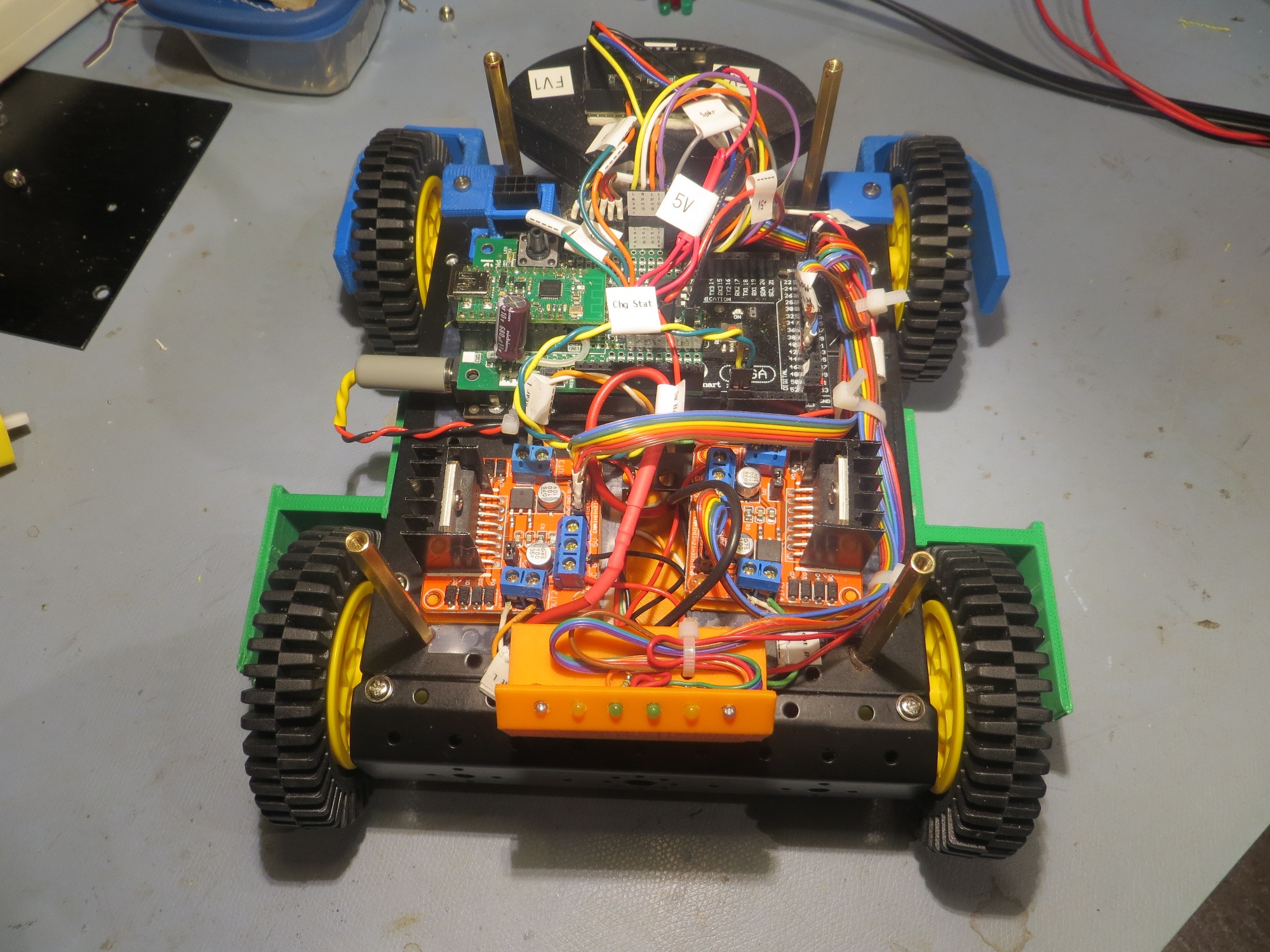
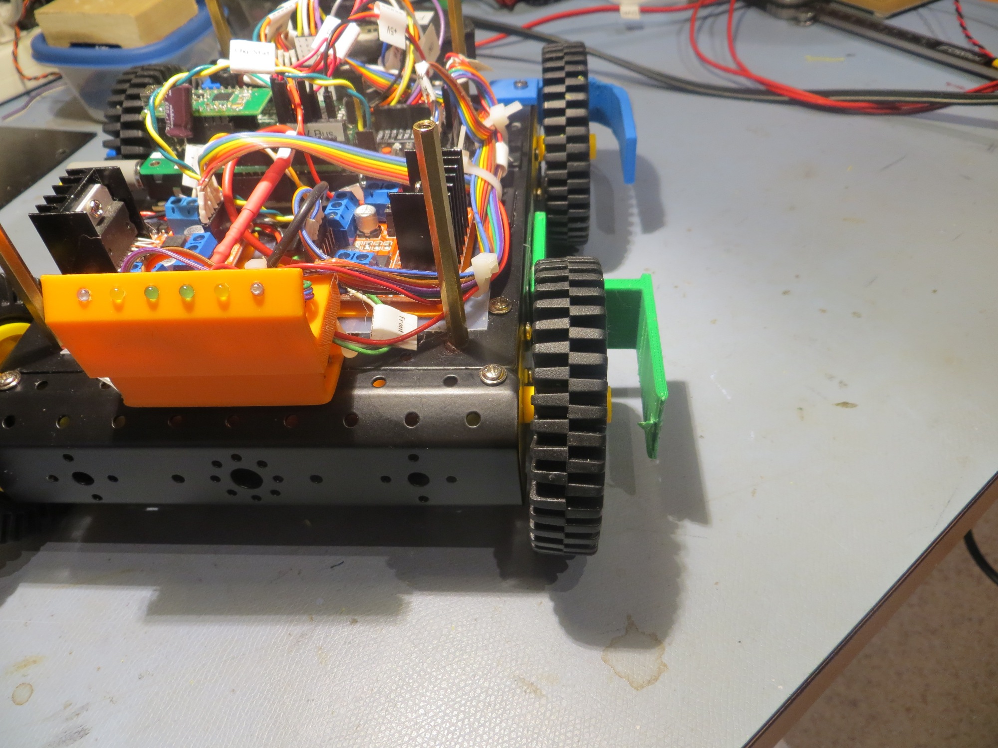
As can be seen in the above photos, the 80mm wheels are now much closer to the chassis. The wheel guards are now much too wide, but I may keep them that way for the moment, as I have already adjusted the charging station lead-in rails to accommodate the (now unnecessary) greater wheelbase – oh well 😉
So, the moral of this little story is: Just because you have a 3-D printer doesn’t mean the solution to every problem is a new 3-D printed piece; and maybe to keep one’s eyes/brain open for even better solutions as they might come along when least expected!
In a recent post, I described my study of the widely available and dirt-cheap TP5100 1/2-cell LiPo battery charger as a possible replacement for my current Adafruit PB1000C-based battery charger. Based on the results of this study, it was clear the TP5100-based system was superior in all respects to my home-brew system:
Twice the charge current (2A vs 1A) means significantly shortened charge times
Much smaller and simpler
Charger current path independent of load path – much lower IR drop
Battery always connected to the system, so no requirement for ultra-low-drop MOSFET diode
Much simpler software – no requirement to monitor status of two separate chargers
No electromechanical relay to screw up.
I constructed a small charger module using some perfboard and a couple of 2-place screw terminals, as shown below (with the previous module shown for size comparison).
New TP5100-based charger module, with previous Adafruit PB1000C-based module below for size comparison. The orange box contains 4 Panasonic 18650 cells. Note the separate charge & load circuits
The following figures show the old and new schematics:
Old battery pack schematic
New battery pack schematic
Now that the load current doesn’t have to go through the charging module, I was able to replace all main battery wiring with #20 wire for lower IR drops, as shown below
Power wiring replaced with #20 wiring, and 2-pin Deans connectors
#20 wiring to main battery buss. Note in-line safety disconnect
The change to the new battery pack also considerably simplified the system hardware and software. The changes to the system schematic are shown below:
Old system schematic. Note the ultra-low-drop MOSFET diode required to keep Arduino Mega alive during charge. and the number of pins required for charge monitoring.
New system schematic. No requirement for diode, as full battery voltage is available at all times. Also, only two pins are required for charge monitoring
The operating system software has also been simplified. Now, instead of monitoring both cell voltages and four different status lines, only two lines have to be monitored. Also, there is now no requirement to correctly sequence the ‘Charger Connect’ and ‘Coil Enable signals in order to accomplish correct charging station connect-disconnect behavior. Now the system simply shuts off the motors when the robot connects to the station, and turns them back on again to disconnect. As an added benefit, the six charge status LEDs have been repurposed to show a crude approximation (based on battery voltage only for the moment) of charge status.
All these changes have caused one minor hiccup in the implementation of the charging station; the new charging voltage is +12V vs +5V as before. As you may recall, the charging station implements a square-wave modulated IR signal, and this signal is produced by a Teensy 3.2 and some associated circuitry, all of which expect +5V. This will require either a dual-output supply, or the addition of an on-board 12-to-5V regulator. This is still up in the air, but I suspect it will land on a simple 3-pin regulator.
So far, all the hardware changes (except for the charging station changes) have been accomplished, but the software changes have yet to be implemented and tested. Stay tuned!
Some time ago I created Bridge Game Reporter (BGR), a wrapper for Ray Spalding’s wonderful Bridge Composer (BC) program, for the Columbus Bridge Center, our local bridge club. Bridge Composer produces really nifty HTML and PDF reports of duplicate bridge games, but using it can become tedious, and non-technically-oriented bridge directors are prone to making mistakes when FTP’ing result files to a website. So, my BGR program automates all that stuff and makes calls into the BC API to make the magic happen. After the inevitable problems and issues, it seemed to be working fine at the CBC, and then Siraj Haji, owner/operator of the Aloha Bridge Club asked me if I would mind sharing the program with him. Siraj had a slightly different setup, and rather than FTP’ing result files to a website, he wanted to email them to just those players who actually played in a particular game, so he and I worked out the strategy for using ACBL player numbers from session reports as a search key into a CSV-formatted email list. After the usual number of mistakes, we got it working. A few days later Siraj mentioned that he also uses Bridge Composer to generate game files for upcoming games, but it was somewhat tedious – could I maybe use my new-found BC superpowers to do something about that? Well, it turns out that the BC guy (Ray Spalding) created a pretty nice API to BC, and provided a WScript/JScript example that did most of what we wanted. After a few days of fumbling around, I figured out most of what was going on behind the curtains, and realized that I could fairly easily add a ‘game generation tool’ to my BGR app to add bulk game generation capabilities. Again after the normal number of mistakes, Siraj reported that this feature seemed to be working – yay!
At some point in this process, after the email feature was added and before the bulk game generation feature, I got another request for the program from another club in the area, so I realized I was going to have to provide an actual installation program and some user documentation. Since I already had this blog site, I decided to use it as the documentation vehicle.
Bridge Game Reporter Features:
Uses Ray Spalding’s Bridge Composer program, which must be installed and active for the magic to work.
Automates the process of calling Bridge Composer with the correct set of files for a particular game.
Optionally automates the process of FTPing Bridge Composer game summary and hand records to a selected website
Optionally automates the process of emailing results to a user-supplied list of email recipients
Automates the process of generating multiple games over a range of dates/times using the ‘Game Generation’ tool.
Main Page:
The main page of the Bridge Game Reporter program is shown below, along with a description of each control area.
Bridge Game Reporter main page
Game Date: The user selects the desired game date from a drop-down calendar display. This date is used to construct the filename to be searched for. The file name format is in the form [yymmdd][session time].ext, where yy = year, mm = month, dd = day, session time = ‘M’ (Morning), ‘A’ (Afternoon), ‘E’ (Evening), or ‘L’ (Late). All input files associated with a particular game will have this format. For instance, for an afternoon game on March 6, 2018, the filename will be 180306A.ext, where ‘ext’ = BRI (or DUP or PBN) for the deal file, BWS for the Bridgemate results file, TXT for the text summary file, HTML for the report output from Bridge Composer, and LOG for the log file optionally created by BGR.
Game Time: The user selects one of ‘Morning’, ‘Afternoon’, ‘Evening’, or ‘Late’. This selection is used to form the ‘MAEL’ suffix to the filename.
Lock Entry Fields: For a particular club setup, most of the fields dealing with file locations can be set once and then never changed again. To prevent inadvertent changes to these fields, this option, when checked, will make them all read-only.
Game Input Folders: The location for the .BRI, .DUP, or .PBN game files, the .TXT summary file, and the .BWS Bridgemate score files. The .BWS file can be skipped, if necessary.
Game Report Folders: The location for the .HTML and the optional .LOG files. This section also contains the ‘FTP to Website’ checkbox and the the URL for the destination website, if this feature is enabled, and the ‘Email to List’ checkbox and corresponding location for the email list document.
Start, Close buttons and logging area: The ‘Start’ button will remain grayed-out until all required input conditions are met, at which time it will become click-able. Clicking ‘Start’ will cause the program to assemble all the required information and send it to Bridge Composer for processing; then it will optionally transmit the results to either a selected website or to addresses on an email list. The ‘Close’ button will close the program. The logging area displays progress and/or error information. If the ‘Save log to folder’ option is checked, then the log file will be saved to [yymmdd][session].LOG in the selected folder.
Set FTP/Email Creds: FTP and/or email server login information (username & password) is saved in the ‘BGR.TXT’ file, which must be in the C:\BGR\ folder (this folder and a default file are automatically created at installation). The format of the BGR.TXT file is
Clicking the Set FTP/Email Creds button will bring up the following dialog box for editing the contents of BGR.TXT. This dialog is password protected, more to prevent inadvertent changes by untrained personnel than for any serious security.
Reset Folders to Defaults: Clicking this button will overwrite the current folder settings with the last-saved set of default settings. This button (and the corresponding ‘Save Current Settings as Defaults’) are almost never used, as the program automatically saves the last set of user settings whenever the program is closed, and automatically restores them the next time the program is launched.
Emailing Results:
The email feature requires four components:
The session summary ([date][session].TXT) file produced by ACBLSCOR containing player names and ACBL player numbers *see 10 July 2021 Update for more info on this
A user-provided file containing email addresses in CSV format (an example is provided)
A user-customized ‘EmailTemplate.txt’ email template file (an example is provided) containing the body of the email to be sent
Any HTML/PDF attachments to be sent. All desired attachments must have the same filename as all the game files for the particular session, with a .HTML or .PDF extension, and must be in the same folder.
The email list must be in CSV format, and must be formatted as follows:
Name,ACBL #,Email Address,Opt out Jody Lastname,R892974,name@ee.net, Marge,L916928,name@hotmail.com, Barb,K778289,name@gmail.com, Daniel Lastname,N184169,name@yahoo.com,yes Luaine,5169593,name@gmail.com,
A ‘yes’ (case-insensitive) in the ‘Opt out’ field will cause that address to be skipped.
The ‘EmailTemplate.TXT’ file format is:
FROM: info@alohabridgeclub.com SUBJECT: Aloha Bridge Club results for [GAMEDATE] – [SESSION] BODY: Aloha,
Thank you for playing. This automated email is intended solely for players in this specific session. Thank you for your support and cooperation.
info@alohabridgeclub.com 614.890.1459
In the above example, the FROM:, SUBJECT:, and BODY: sections are required fields, and must be placed as shown. [GAMEDATE] and [SESSION] are optional fields that will be replaced by the actual game date and the actual session time (‘Morning’, ‘Afternoon’, etc). The resulting email using the above template looks like the following, where ‘[GAMEDATE] – [SESSION]’ was replaced by ‘February 26, 2018 – Evening’
Game Generation Tool:
The game generation tool is intended to automate the process of batch-producing dealer (.PBN or .BRI) files for games over a range of dates and session times. if, for instance, you wished to produce the deal files for all Monday, Wednesday, and Friday afternoon and evening games for the entire month of April you could simply set up the dates and times, and press one button to generate all the game files.
The game generator tool is accessed from the main Bridge Game Reporter page by selecting the ‘Game Generator’ item under the ‘Tools’ menu. The tool dialog is shown below, along with an explanation of each control section.
Start/End Date: The starting and ending dates for game generation (inclusive)
Game Times: Select one or more game time checkboxes to have that session time’s game generated for every applicable date. Checking ‘All’ will enable all times, and unchecking ‘All’ will disable all times.
Game Days: Select one or more game day checkboxes to have games generated for all enabled session times for all those days of the week within the selected date range, inclusive. Checking ‘All’ will enable all days, and unchecking ‘All’ will disable all days.
Selection Summary: This is a read-only running summary of the number of days, times, and total games to be generated. It’s a good idea to check that the ‘Tot Games’ number is what you expect, before starting the generation run.
Destination Folder: The folder to be used as the destination for generated game files. This folder must exist, and must contain the template file ‘handrecord.pbn’ (see below)
Output Format: Bridge Composer can create game files in either .PBN or .BRI format – simply select which one is desired.
Number of boards to generate: Type in the desired number of boards to generate per game. This will typically be 24, 27, or 36, but can be anything. I suggest setting this to 2 or 3 when first getting used to the program.
Generate Games: Starts the generation process. Note that this button won’t be enabled (click-able) until all the prerequisites are met (start/end date, days of week, session times, destination folder, etc). If the button won’t enable, check the log for helpful messages.
handrecord.pbn template file: This is a required file, and it must be present in the folder selected in the ‘Destination Folder’ entry field. This template file is used by Bridge Composer to customize hand record output for your club or organization, as shown below:
2-board game generated using the default ‘handrecord.pbn’ file
The above figure shows a 2-board game generated by Bridge Composer using the default ‘handrecord.pbn’ file. The text in the title area above can be customized for your own club using Bridge Composer’s ‘Format Title Area’ menu as shown below
Once the required customizations have been accomplished, simply save the result back to ‘handrecord.pbn’, and they will show up the next time a game is generated. Note that Bridge Composer supports many other customizations to the ‘handrecord.pbn’ template, but that’s an exercise that is left up to the user ;-).
Installation:
Download and launch BridgeGameReporter.msi to install Bridge Game Reporter on your (Windows only – not MAC) PC. The installation program will do the following:
Install the BGR application in C:\ProgramFiles(x86)\Bridge Game Reporter
Create the folder C:\BGR\ and place a default BGR.TXT file there for ftp/email credentials
Create another BridgeGameReporter folder in your ‘My Documents’ folder to hold the ‘handrecord.pbn’ file required for game generation, and the ‘EmailAddressList_Sample.csv’ and ‘EmailTemplate_Sample.txt’ sample files.
Place a red heart-shaped ‘BGR’ icon on your desktop
Once the installation completes, launch the program using the desktop icon, and fill in fields as required/desired. Note that if you want to use the game generation tool, you should set the Destination Folder field to the ‘BridgeGameReporter’ folder in your ‘My Documents’ folder.
09 July 2021 Update:
When the Aloha Bridge Club restarted face-to-face bridge recently, Siraj Haji ran across a problem when he tried to use BGR to email results to game participants. He got the following error message from the part of the program that uses the Gmail SMTP server:
1
Failed with message:The SMTP server requiresasecure connection orthe client was notauthenticated.The server response was:5.7.0Authentication Required.Learn more at
At first I thought this might be a standard “your username and/or password is incorrect” kind of message, and then later I thought it might be due to Google moving to an SSL based SMTP server during the pandemic. As it turns out, both of these suppositions were wrong. The actual problem was due to Google de-activating the required ‘Less less secure app access‘ setting during the year+ of inactivity on the account. There is actually a note associated with the setting that says “Google will automatically turn this setting OFF if it is not being used”. After turning it back ON again, I was able to successfully send an email using the SMTP server from my debug version of the BGR app (and Siraj confirmed that doing the same thing on his account allowed him to email out the results from his latest game). See the screenshot below:
screenshot from my Google account settings security page, showing the ‘less secure app access’ setting turned ON again.
While I was looking through the BGR code trying to find the problem that was eventually traced down to the above setting, I noticed something that might, or might not, be a bug. The following code:
calls
SearchForMissingFile(TxtFilename,tbSummaryFolder.Text,"TXT") to see if there is a file with the right date and ‘gametime’ configuration, but maybe extra letters. The
SearchForMissingFile(TxtFilename,tbSummaryFolder.Text,"TXT") function is shown below:
//concatenate folder & filename to form final filename
namestr=foldername+"\\"+filestr;
}
else
{
AppendToLog("Eror in GetFullFilename()",Color.Red);
}
returnnamestr;
}
So, if the program can’t find the normal ‘YYMMDD[M/A/E/L].TXT’ file, it looks for ‘YYMMDD[M/A/E/L]P.TXT’ and offers to use it instead. However, it also renames the file (by removing the extra ‘P’), and I don’t know why I decided to do that, rather than, say, copying the file so that both versions would exist. I asked Siraj about this, but it may be that the reason is lost in antiquity.
10 July 2021 Update:
I got the following email back from Siraj when I asked him about the ‘P’ file:
We use the ACBL numbers to find email addresses in a text file. ACBLScore does not include the ACBL number In their Press + Recap report. We run a Short Press report to get the ACBL numbers. That report that’s the ‘P’ in the file name. Recap sheet does not.
So, the mystery is now solved. Siraj generates the ‘P’ file from the regular ACBLScore ‘recap’ file in order to add in ACBL player numbers, to facilitate extraction of email addresses from the overall email address database. Note that the regular ‘recap’ file is still required, as it contains the Board #/Matchpoints grid for each pair number, and is the file that is sent to BridgeComposer to be incorporated into the HTML documentalong with the double-dummy analysis for the game boards.
This then brings up more questions – what happens to the original (non ‘P’) ACBLScore recap output file? Why not just replace the ACBLScore (non ‘P’) file with the ‘P’ version but with the original ACBLScore [GAMEDATE][GAMETIME].TXT filename and avoid the whole problem of not finding the original file, searching for and finding the ‘P’ version, and then offering to then rename it to the original ACBLScore filename?
After another conversation with Siraj, I now understand the following:
The regular ACBLScor summary file ([GAMEDATE][GAMETIME].TXT) file is required for generating the proper HTML file layout from Bridge Composer. The ‘short press’ ([GAMEDATE][GAMETIME]P.TXT) format does not contain all the information needed
The ‘short press’ ([GAMEDATE][GAMETIME]P.TXT) format is also required (for the ’email’ option) because that is the only output that connects ACBL player numbers with player names for the game, and the player numbers are required to extract email addresses from the email list. Using just player names doesn’t work, because they are not necessarily unique, but player numbers are.
The last piece of the puzzle is the mystery of the dialog box that popped up during my initial testing, as shown below:
This dialog led me on a merry chase, as initially I thought (wrongly, as it turned out) that this offer was somehow a good thing and that the extra ‘P’ was just a typo or something. What I didn’t realize at the time was that not having a ‘regular’ summary file was an abortable condition, and that the ‘P’ file wasn’t just due to a typo – the ‘P’ file is also required when the ‘Email to List’ option is selected. In this case, both files are required, and so I should have selected ‘NO’ here (which would have caused the program to abort).
Apparently this feature was incorporated into the program before I added the email-to-list feature for Siraj, to cover cases where the summary file name had somehow gotten corrupted with an extra space or other character, and the situation could be recovered by finding and renaming the errant file name. This works great, right up until the ‘P’ file got added for Siraj’s email feature.
09 June 2022 Update:
Siraj called me with a problem; as it turns out, Google Gmail turned off its ‘use less secure apps’ option as of 31 May 2022, and the Aloha Bridge Club game results email capability went away – oops!
So, I started digging into the problem, and discovered that the workaround was to use their ‘App Password’ option, which turned out to be pretty simple to do. Here’s the link to their help file entry, and I have supplied some screenshots below to show the process, using my Google account – the process should be identical for Siraj’s account.
Open your Gmail client and click on the ‘Google Account’ button, as shown below:
Google Gmail Account Button
Click on ‘Manage Your Google Account’
Manage Your Account button
Click on the ‘Security’ menu item on the left:
Scroll down to the ‘Signing in to Google’ section as shown below:
Make sure 2-Step Verification is turned ON
Make sure 2-Step Verification is turned ON. If it was OFF, turn it ON and go through the process of establishing 2-step verification.
Click on ‘App Passwords’ as shown below. You may or may not have any app passwords already – I have a couple of data backup applications that use Google Drive, so I already had app passwords for them.
Click on ‘App passwords’
At this point, Google will require you to provide your account credentials again. This is your normal Google login username and password.
Log in again using your normal Google account credentials
This will bring up the ‘App passwords’ screen. Note that my screen shows that I have already created an app password for ‘Bridge Game Reporter’ – your screen may or may not have any entries in the ‘your app passwords’ list. At the bottom are two drop-down lists – ‘Select app’ and ‘Select device’; both will have to be defined. As shown below, the ‘Windows Computer’ selection has been made for the ‘device’:
Select ‘Windows Computer’ for the device
For ‘Select app’, choose ‘Other (Custom name)‘ as shown:
Choose ‘Other (custom name) for ‘Select app’
The ‘Other’ selection brings up a text entry box where you can type in the app name (‘Bridge Game Reporter’) in our case, as shown below. Note that the ‘Generate’ button is now active:
Type in ‘Bridge Game Reporter’ and click on ‘Generate’
The next screen shows the app password generated by Google for this device and application. Copy/Paste the password from the yellow box to a temporary location. This password will be used, along with your normal user name (‘paynterf@gmail.com’ in my case) in the ’email creds’ dialog box in the Bridge Game Reporter app. Then click on ‘Done’ to exit the box. You will get a ‘Security Alert’ from Google noting that someone has created an app password. You can safely ignore this.
copy/paste yellow box contents to a temporary location
Launch Bridge Game Reporter, and click on the ‘Email Creds’ button at the bottom of the window and enter the access password. The access password is in the BGR.TXT file located in the C:\BGR folder:
This will bring up the email/ftp credentials dialog. In the ‘Email Credentials’ section, make sure the ‘SMTP Host’ is ‘smtp.gmail.com’ as shown, and the ‘Username’ entry is your normal Google username. Then paste the saved application password into the ‘Password’ box, and click on ‘OK’.
paste the ‘App password’ here
At this point, you should be good to go. When Bridge Game Reporter connects to GMail’s SMTP server at ‘smtp.gmail.com’, it will supply the username and password entered above. At least in my case, this worked seamlessly – your mileage may vary!
I have been working on Wall-E2, my autonomous wall-following robot, for almost three years now, and it seems like I have been struggling with the battery and charger arrangement for that entire time. I started out with 4 AA batteries, but quickly moved on to a pair of Sparkfun 2000mAh ‘flat-pack’ cells with Sparkfun chargers, with a relay to switch the batteries from series (RUN) to parallel (CHG) wiring. This worked, but not very well. The flat-pack batteries weren’t a good match for motor control, and I kept burning up charger modules as well. After struggling with this through several iterations, I finally abandoned it entirely in favor of a 7.4V 20C LiPo RC battery and an external charger. This worked much better, but forced me to manually disconnect the battery from the robot and charge it externally – not at all what I wanted. Later on I made another run at the 2-cell series/parallel switching strategy for charging, this time using Adafruit Powerboost 1000C charge modules, each capable of 1A charge rates. Again this worked (actually quite well), but I recently discovered that it has a fatal flaw – this design imposes significant IR drops on the way from the battery terminals to the motors.
Unfortunately, the available technical information on this module is also next to nothing, and what does exist is all in Chinese. Still, this module has the potential for vastly simplifying my charger setup, so I thought it was worth the effort to perform a thorough study.
In a previous post, I described an Arduino controlled charge/discharge test setup for testing operation of my 2-cell parallel/series switched setup, so I decided to modify it for evaluating the TP5100 module, as shown below
View of TP5100 module showing RUN & CHG indicator connections
Charger test setup, in discharge mode (note 1.1A discharge current)
Charger test setup, in charge mode (note 1.8A charge current)
TP5100 Module Test Circuit
Using this setup, I was able to cycle the battery between a 7.5Ω load and the TP5100 charge module. In order to keep the cycle times down to a dull roar, I set the software to switch to charge when the battery voltage dropped below 7.5V, resulting in the plots shown below.
In this case, the discharge current was about 1.1A, and the observed charge current was about 1.8A. The TP5100 modules seems to work as advertised – with a 12V 5A power supply and a partially charged battery, it successfully charged my 2-cell LiPo pack terminated the charge at about 8.4V (I’m not sure if it is terminating based on current or voltage).
Over the next couple of days, I performed three complete charge/discharge cycles using this same setup. Discharge was terminated at 6V, and charge was terminated when the TP5100 ‘complete’ output changed from open-circuit to active-low. As can be seen in these charts, performance was very consistent – almost 6 hours run time into a 7.5V load, and about 4 hours for a complete recharge.
So here’s what I know now about the TP5100 module
When the ‘1-cell/2-cell’ jumper selector is shorted to select 2-cell, the output voltage stabilized at 8.4 with a 10-15V DC input (I used a 12V 5A supply for the tests). Below about 10V, the output voltage falls below 8.4V
with a partially charged battery stack, output current was about 1.8A at the start, tapering to below 200mA at termination
There is an onboard Red/Blue LED and solder holes for an external bi-color LED. The onboard LED states are:
RED = Charging
Blue = Finished
Both the onboard and external LED connections are tied to +V via the same 1K current limiting resistor. This resistor is routed to the center hole of the 3-hole external LED breakout. The rightmost hole is tied to an open-collector gate that goes LOW upon charge termination, and the leftmost hole is tied to an open-collector gate that goes LOW upon charge initiation. In my testing circuit above, these lines are labelled ‘Fin’ and ‘Chg’ respectively and were routed to digital inputs with 20K pullups on the Arduino UNO.
This is NOT a balance charger – so there may be differences in cell voltages over time. If this is a potential issue, then separate cell protection modules like these should be installed.
Here’s an annotated photo showing the pertinent features:
So, it looks like this TP5100 module will work fine for my 2-cell LiPo application, with the addition of an external 2-cell protection module like the one noted above. Not only will this solve my original IR drop problem, but it is much smaller and simpler too, as shown in the following size comparison shot. Oh well, at least I had a lot of fun building up and testing the original charger module ;-).