Posted 15 April 2017
In my previous post on this subject, I described some IR homing tests with and without the overhead incandescent lights, and the development of a ‘sunshade’ to block out enough of the IR energy from the overhead lamps to allow Wall-E2 to successfully home in on the IR beam from the charging station. At the conclusion of that post, I had made a couple of successful runs using a temporary cardboard sunshade, and thought that a permanent sunshade would be all that I needed.
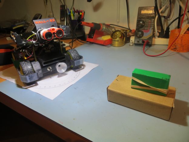
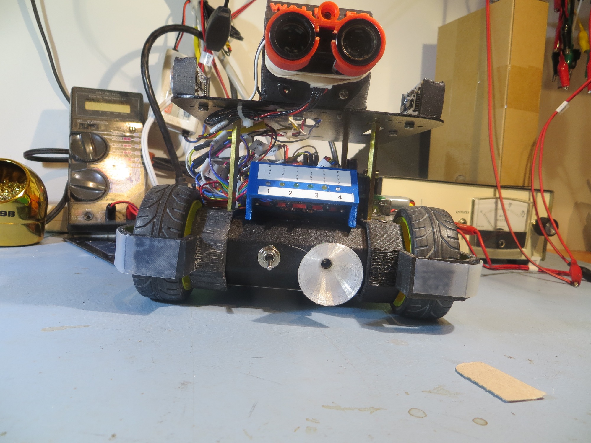
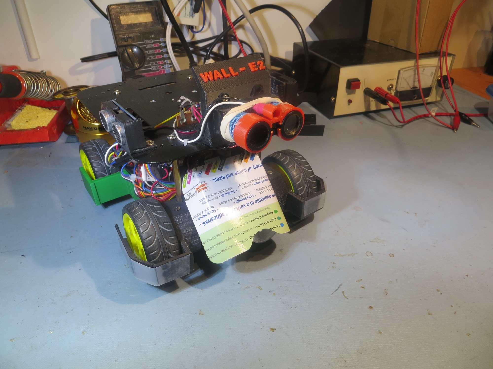
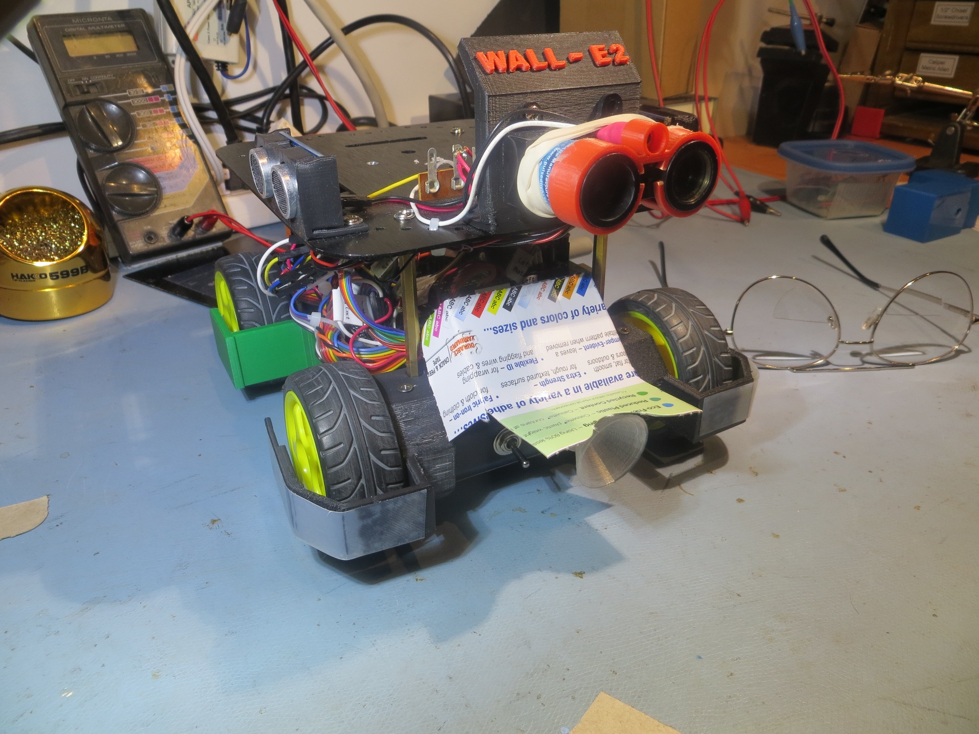
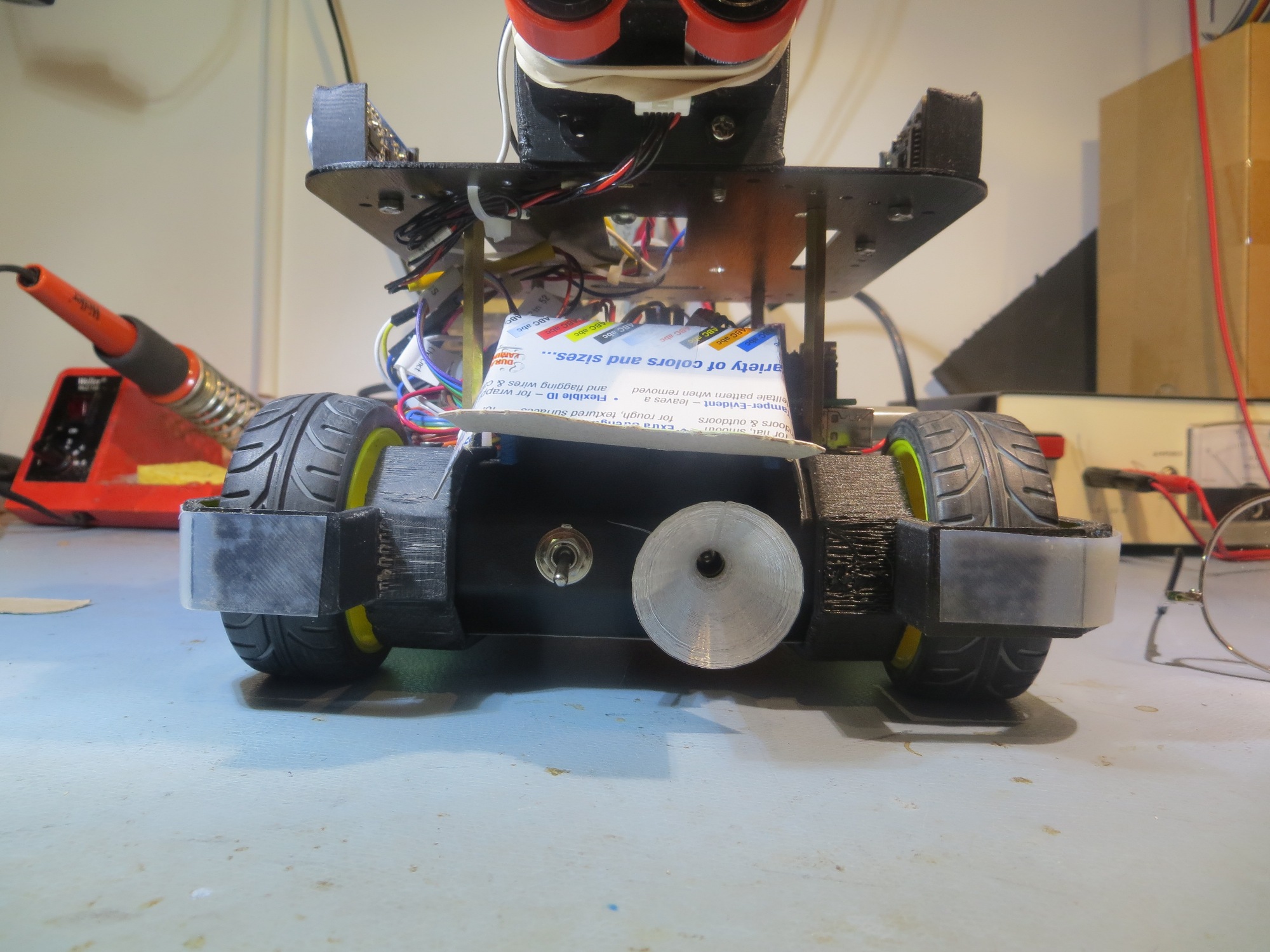
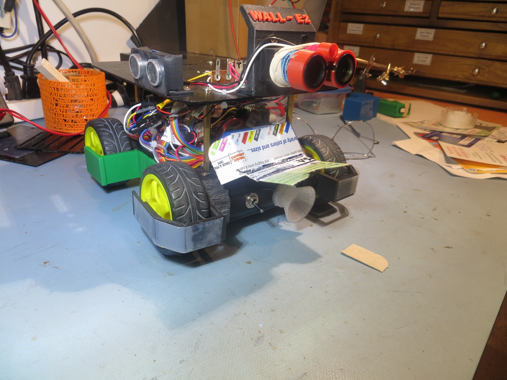
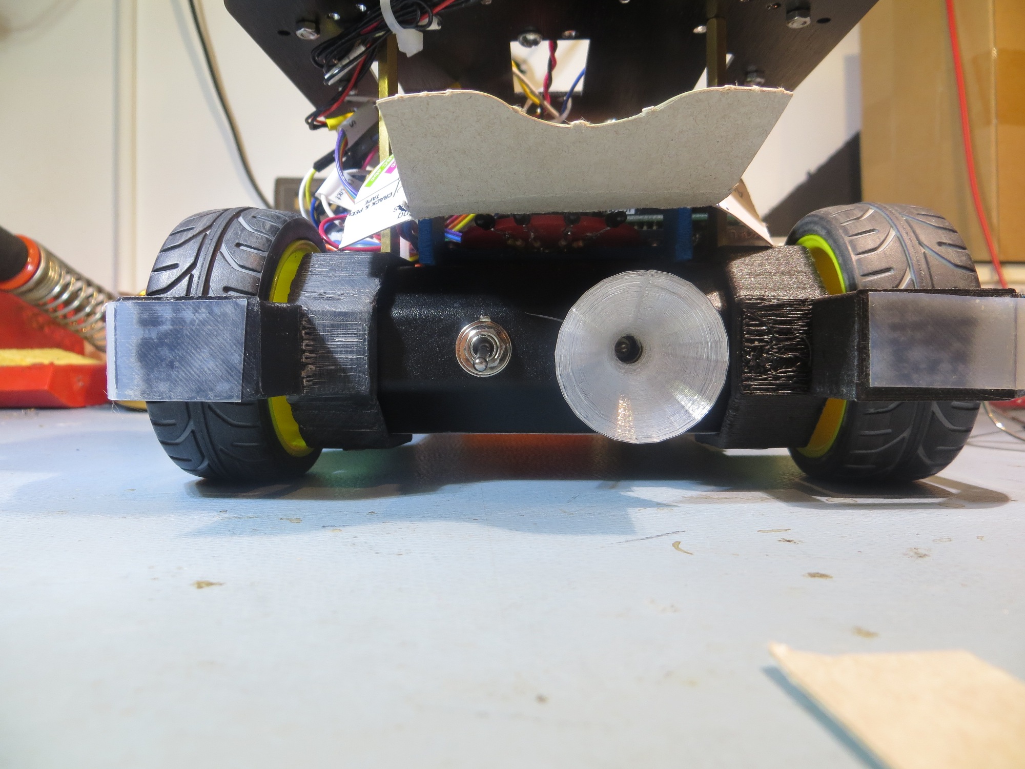
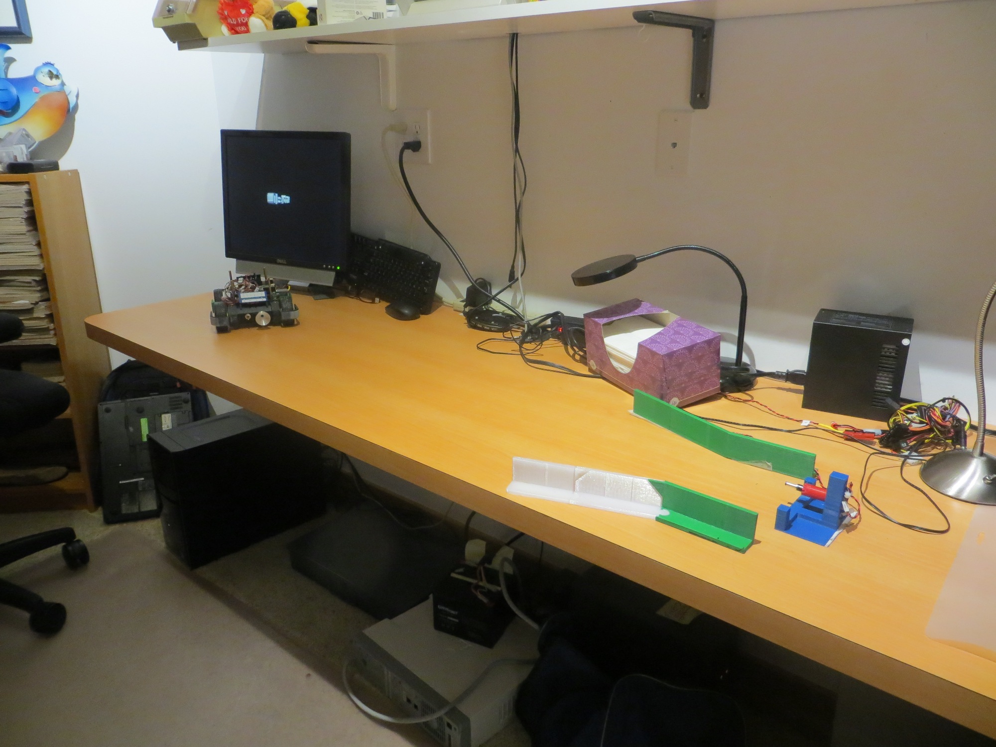
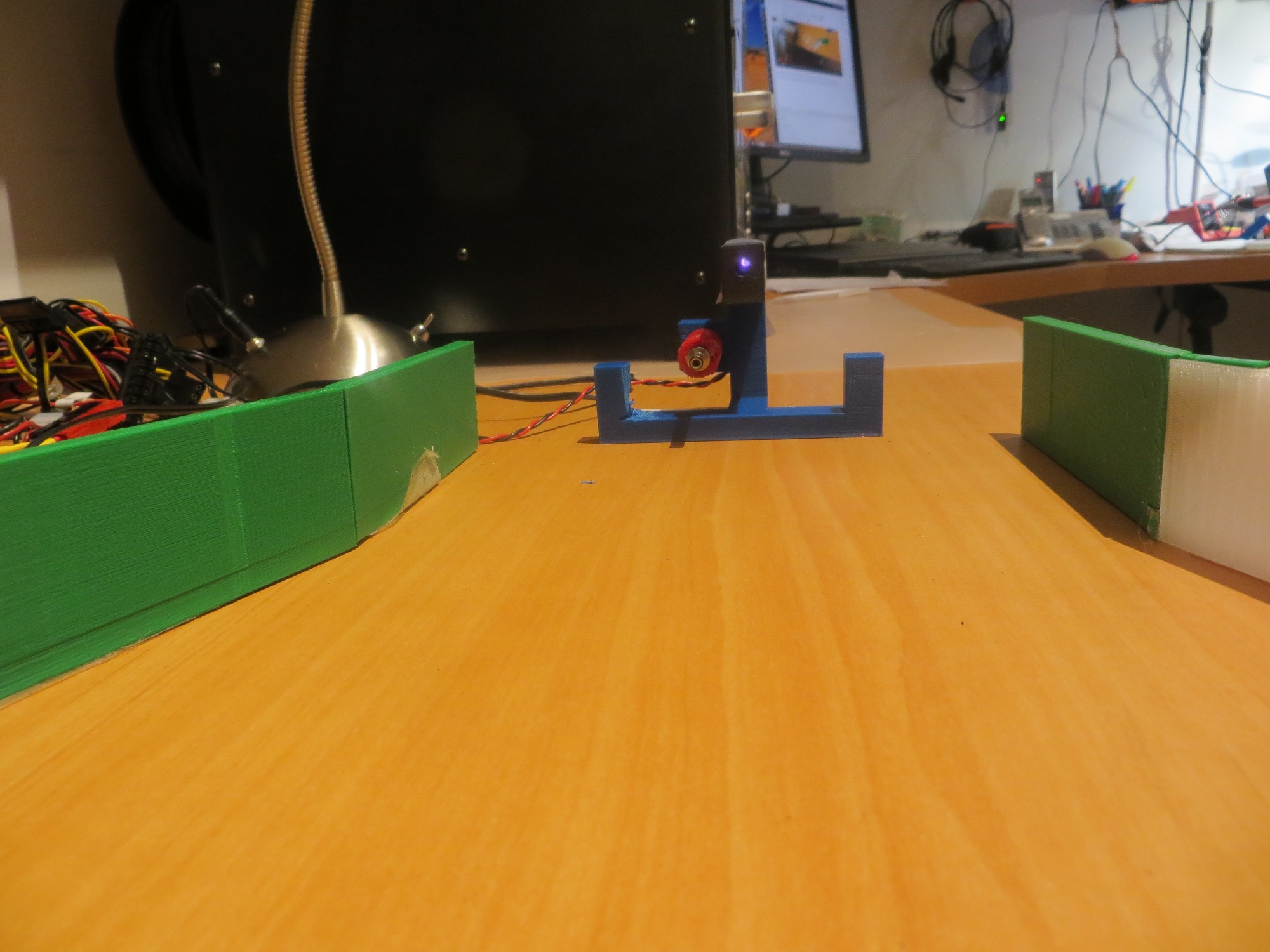
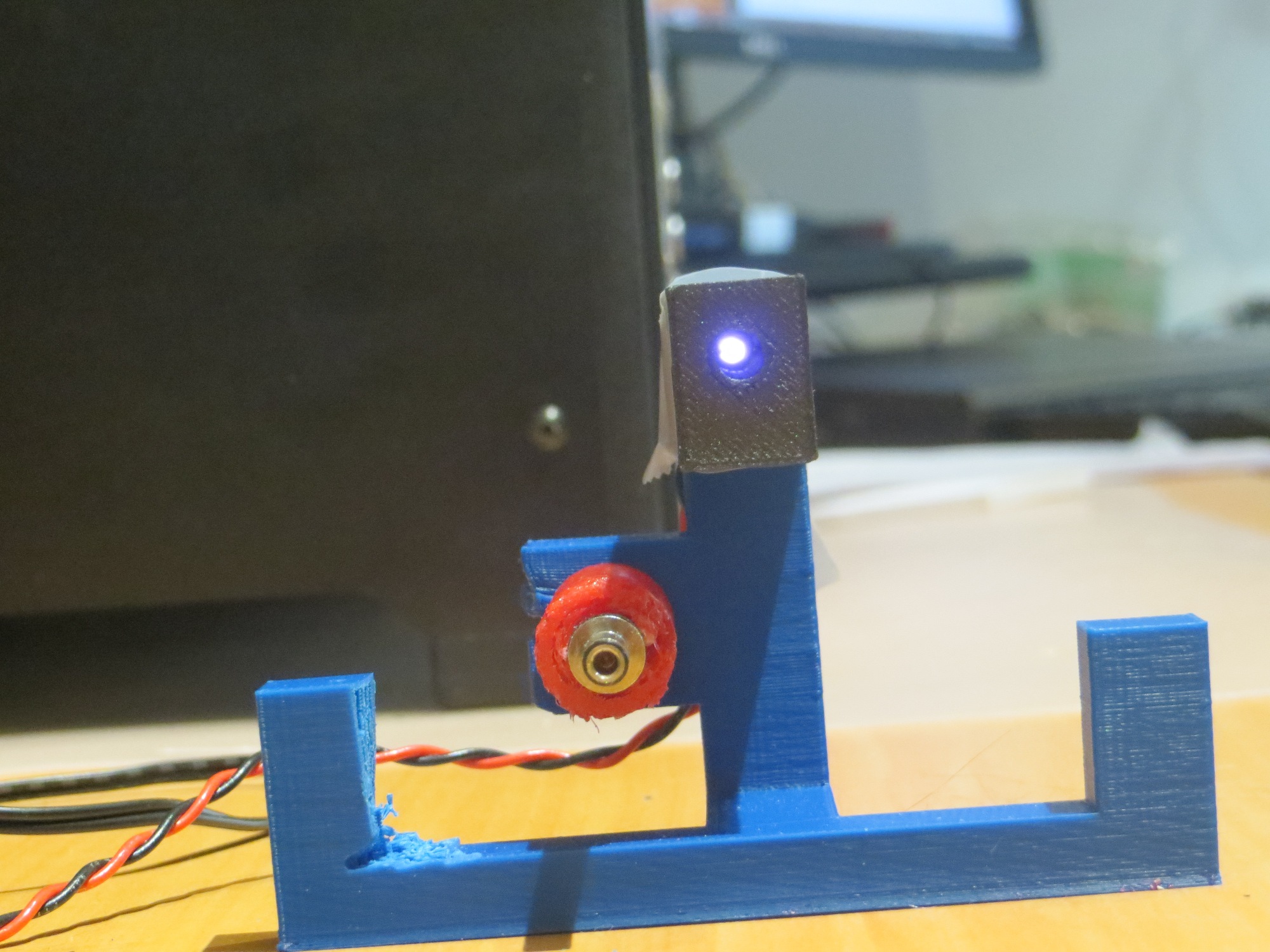
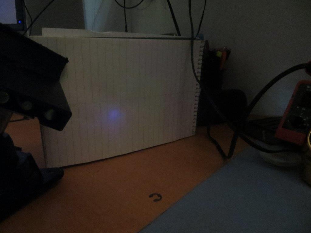
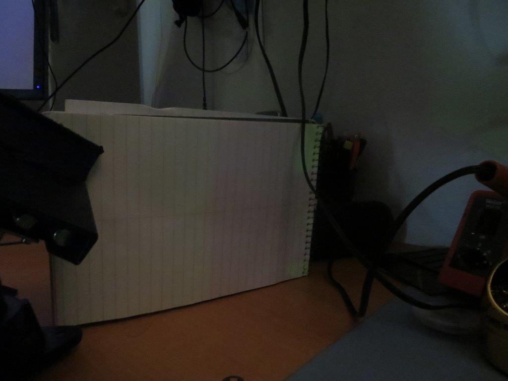
However, after installing the sunshade (shown below), I discovered that the homing performance in the presence of overhead IR lamps was marginal when the robot’s offset distance from the wall was more than about 50 cm.
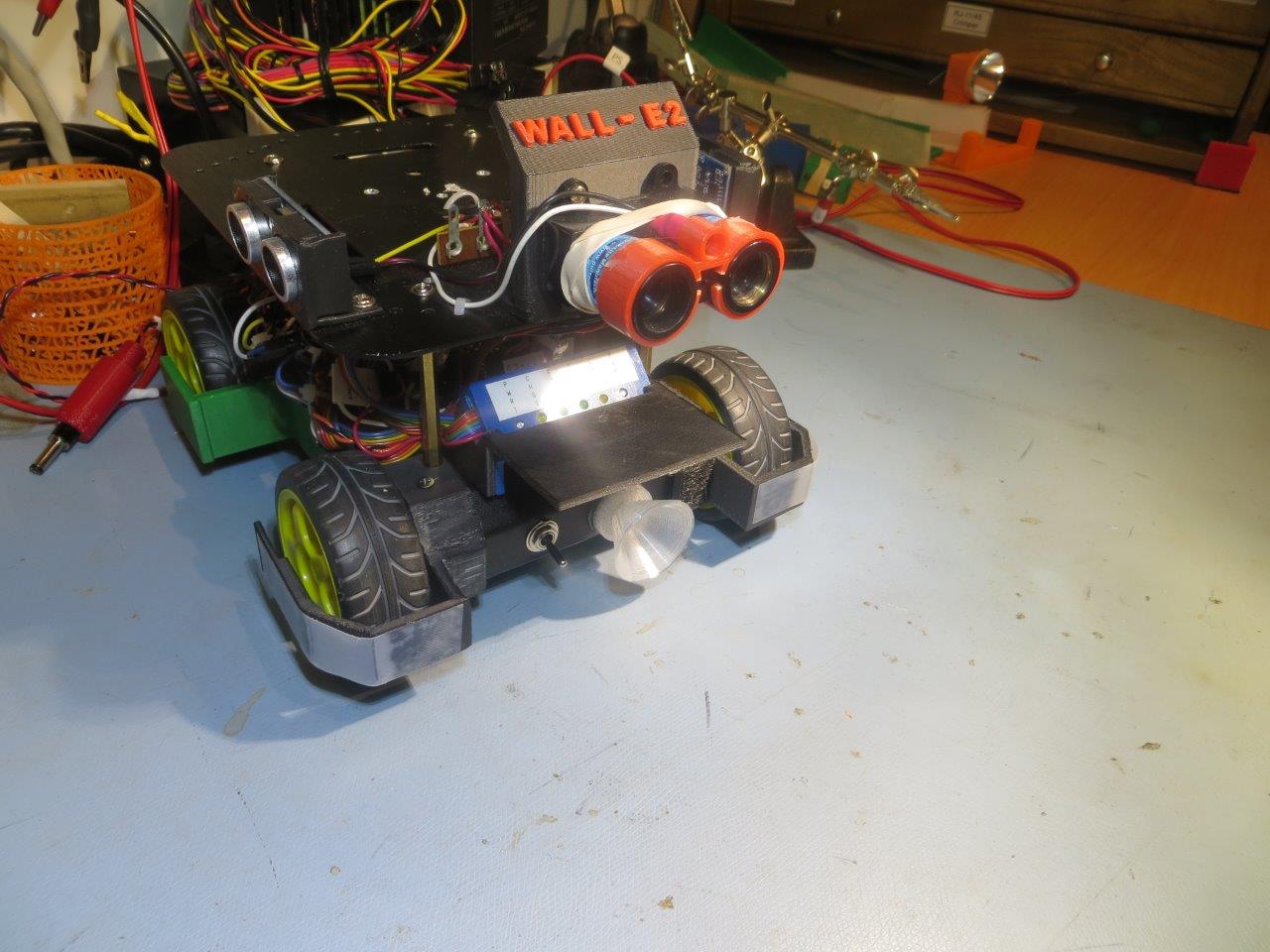
Sunshade, oblique view
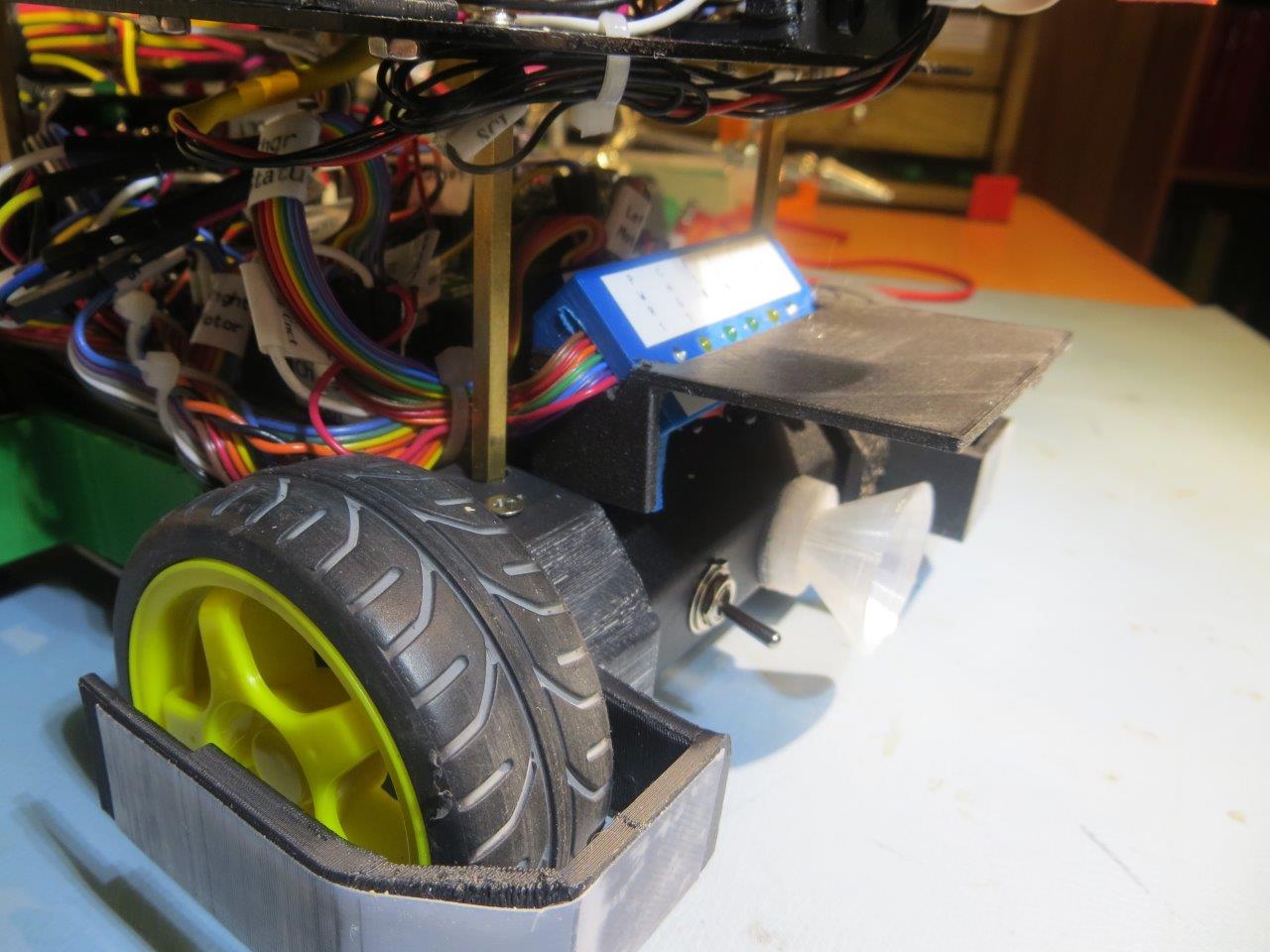
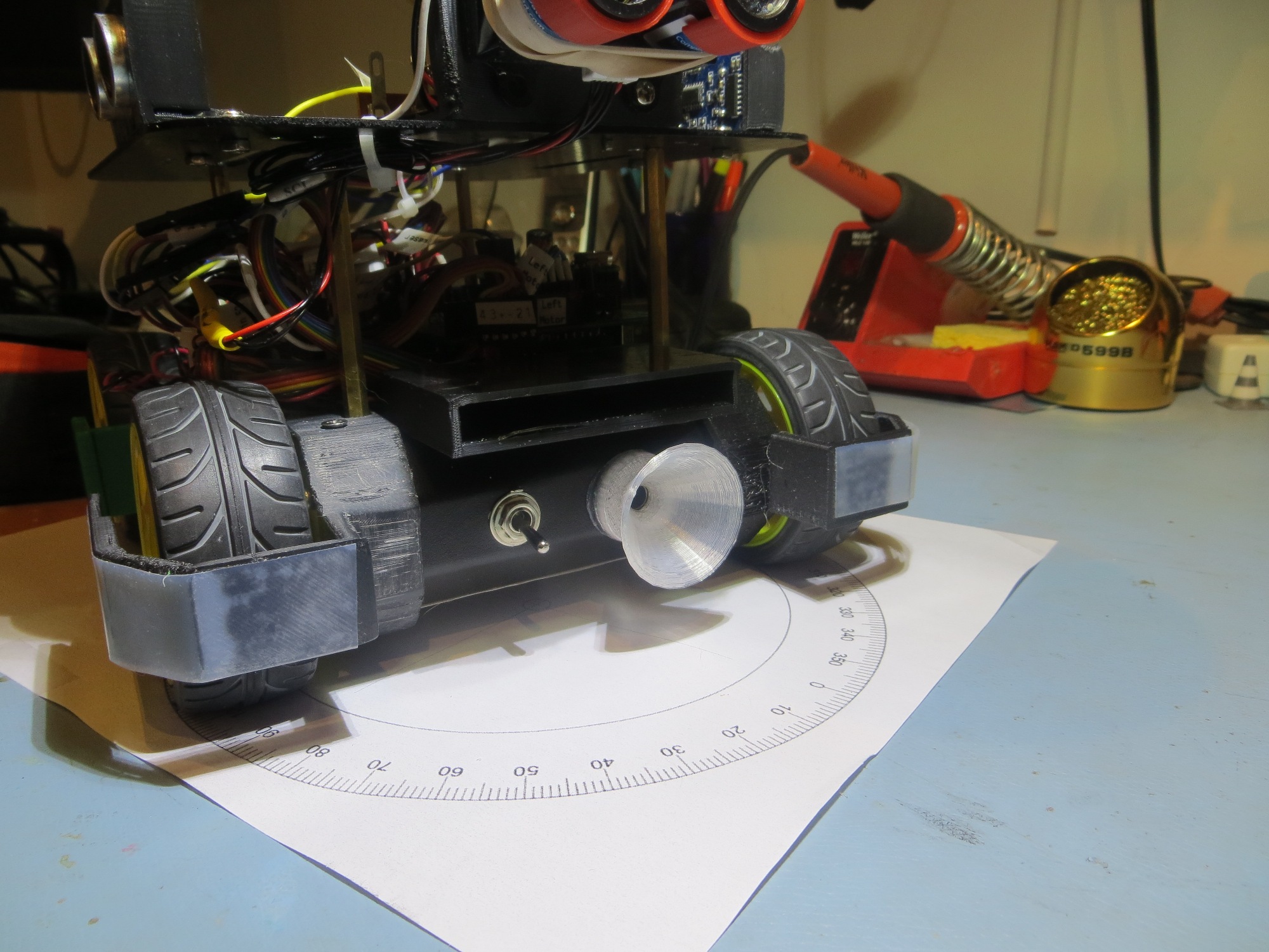
Sunshade, side view
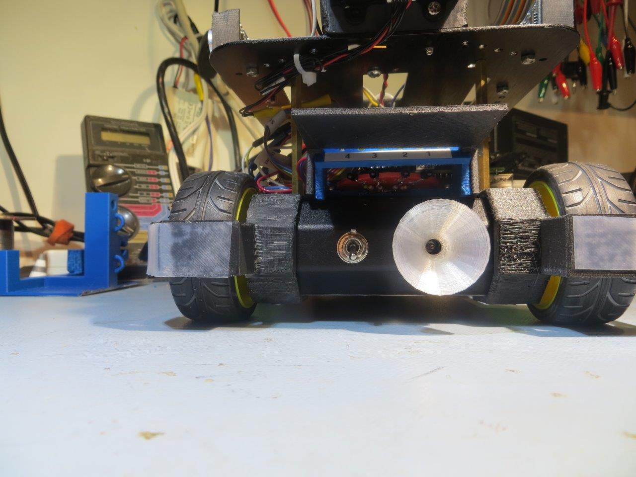
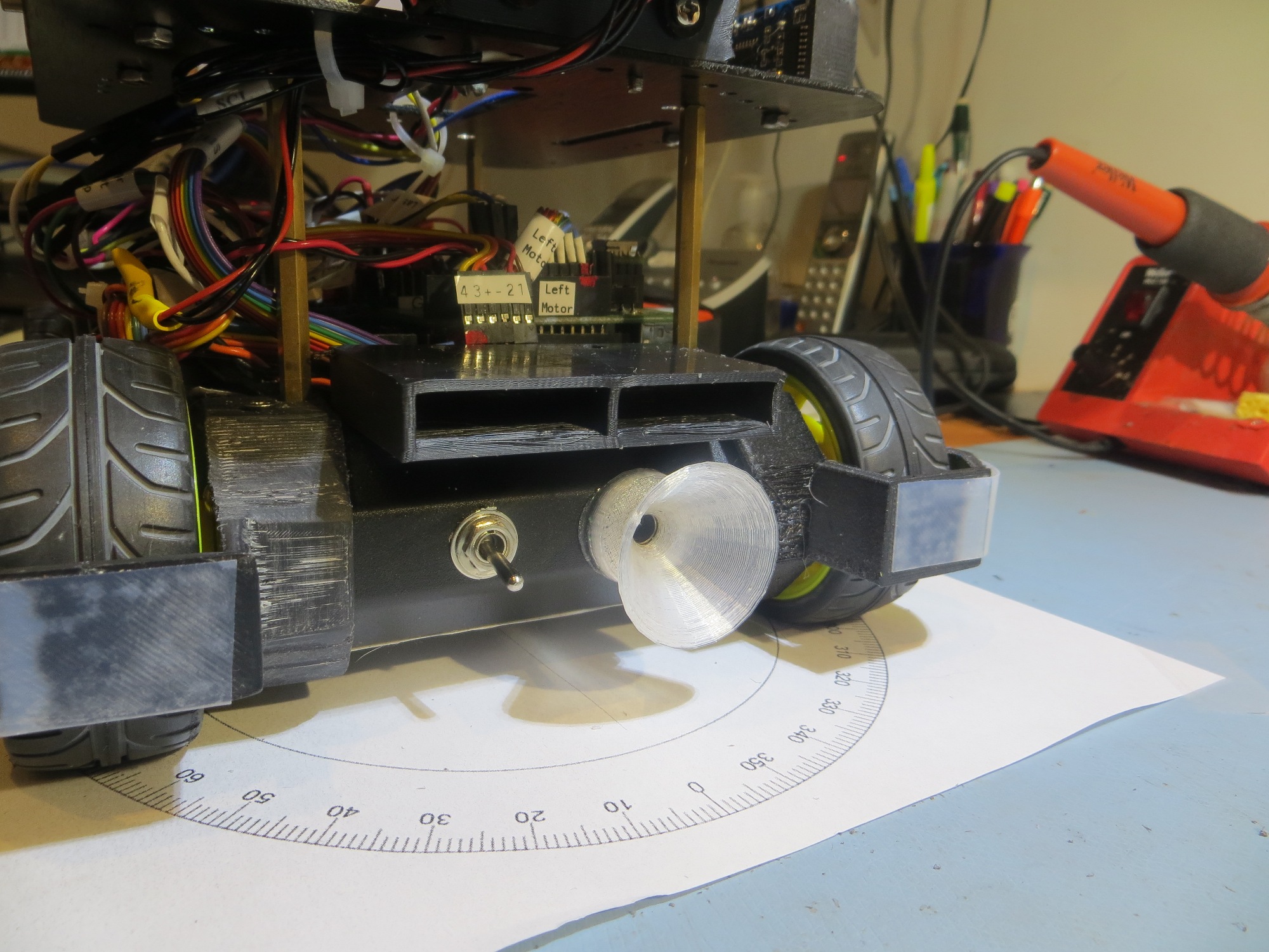
Sunshade, front view
Apparently the IR interference was causing the robot to not respond to the IR beam until too close to miss the outer lead-in rail. This issue was explored in an earlier post, but I have repeated the relevant drawings here as well.
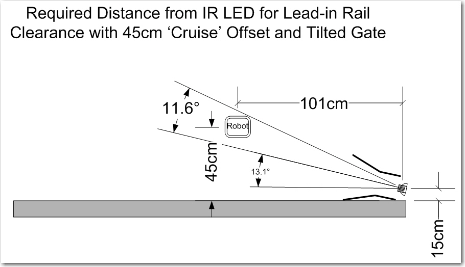
Tilted gate option. The tilt decreases the minimum required IR beam capture distance from about 1.7m to about 1.0m
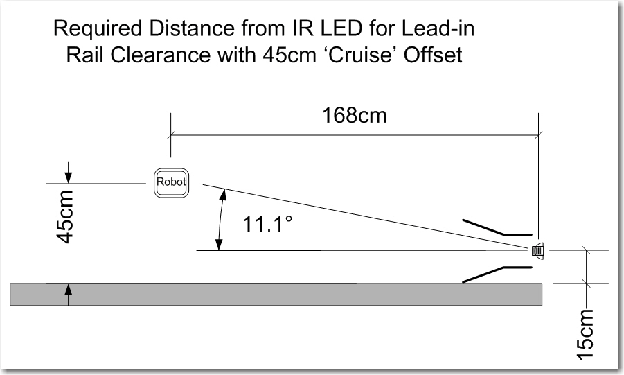
Capture parameters for the robot approaching a charging station
When the robot is ‘cruising’ at more than about 50 cm from the tracked wall, the IR interference from the overhead lamps prevents the robot from acquiring the charging station IR beam until too late to avoid the outer lead-in rail, even in the 13 º tilted rail arrangement in the first drawing above.
So, what to do? I am already running the IR LED at close to the upper limit of the normal operating current, so I can’t significantly increase the IR beam intensity – at least not directly. I can’t really increase the size of the ‘sunshade’ dramatically without also significantly affecting the IR beam detection performance. What I really needed was a way of increasing the IR beam intensity without increasing the LED current. As it turns out, I spent over a decade as a research scientist at The Ohio State University ElectroScience Lab, where I helped design reflector antenna systems for spacecraft. Spacecraft are power and weight limited, so anything that can be done to improve link margins without increasing weight and/or power is a good thing, and it turns out you can do just that by using well-designed reflector dishes to focus the microwave communications energy much like a flashlight. You get more power where you want it, but you don’t have to pay for it with more power input; the only ‘cost’ is the insignificant added weight of the reflector structure itself – almost free! In any case, I needed something similar for my design, and I happened to have a small flashlight reflector hanging around from a previous project – maybe I could use that to focus and narrow the IR beam along the charging station centerline.
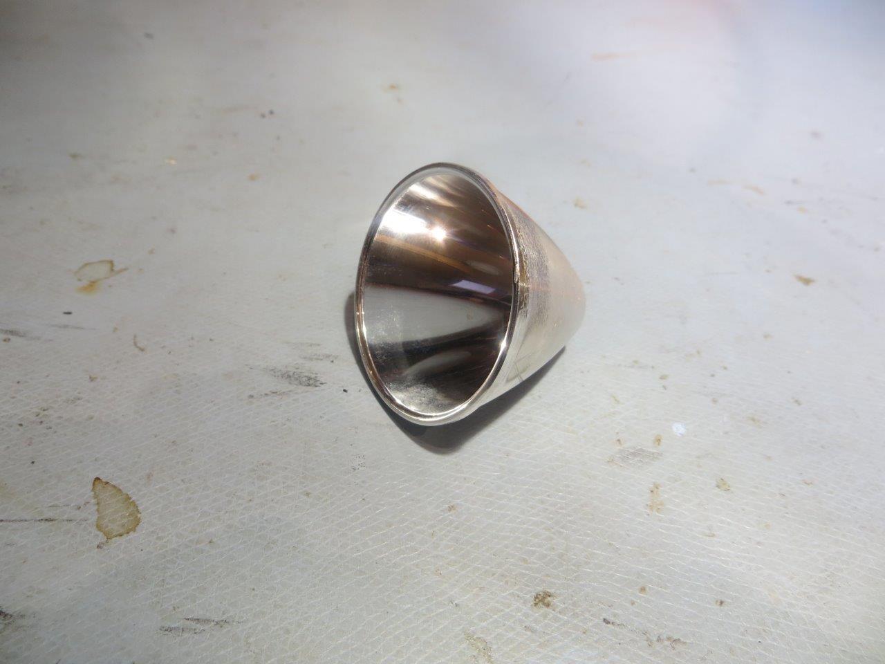
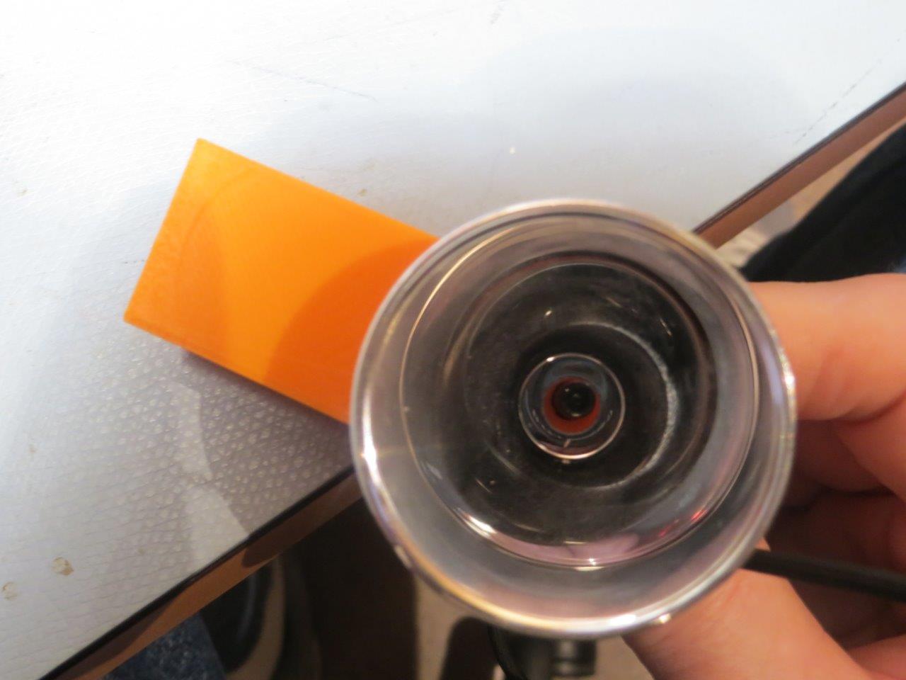
LED flashlight reflector
So, using my trusty PowerSpec PRO 3D printer and TinkerCad, I whipped up an experimental holder for the above reflector, as shown below
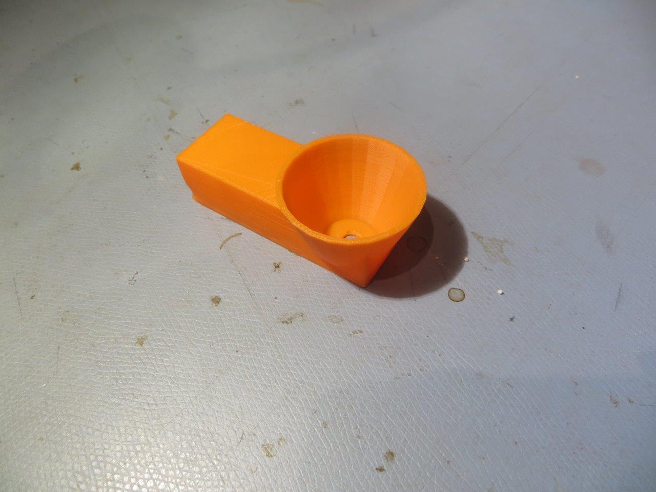
Experimental 3D-printed flashlight reflector holder
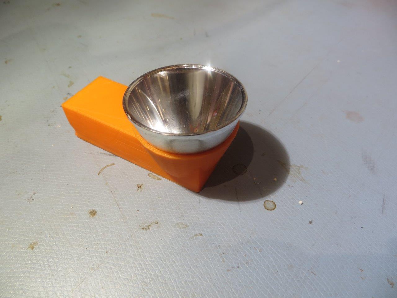
Reflector mounted on experimental holder
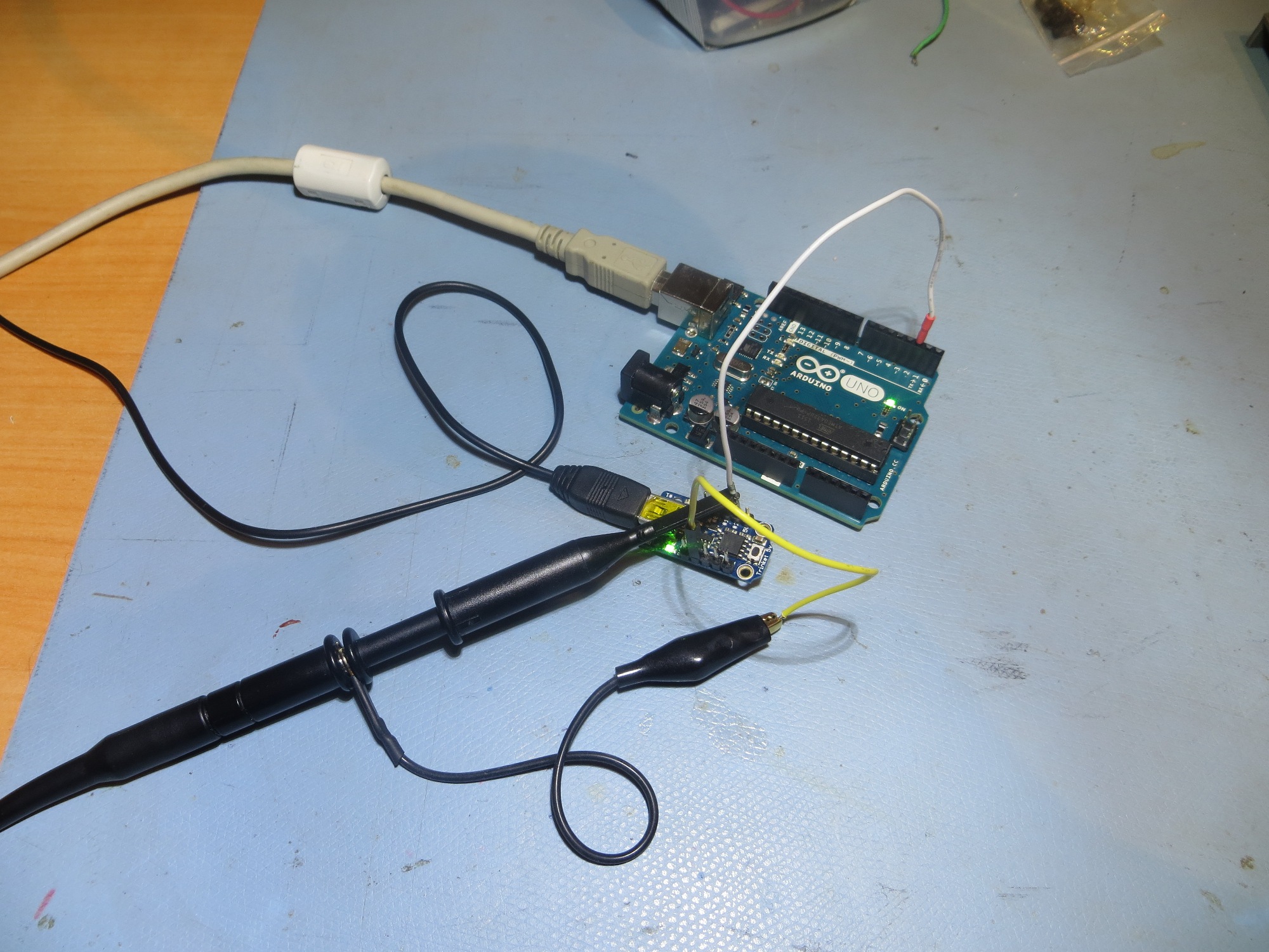
IR LED mounted on reflector
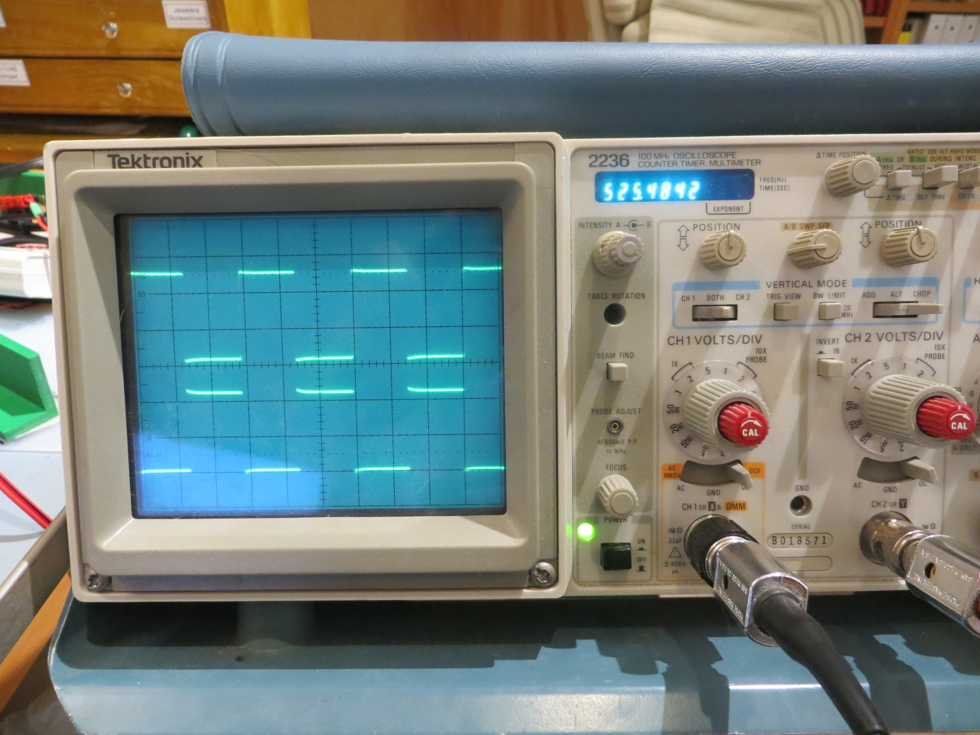
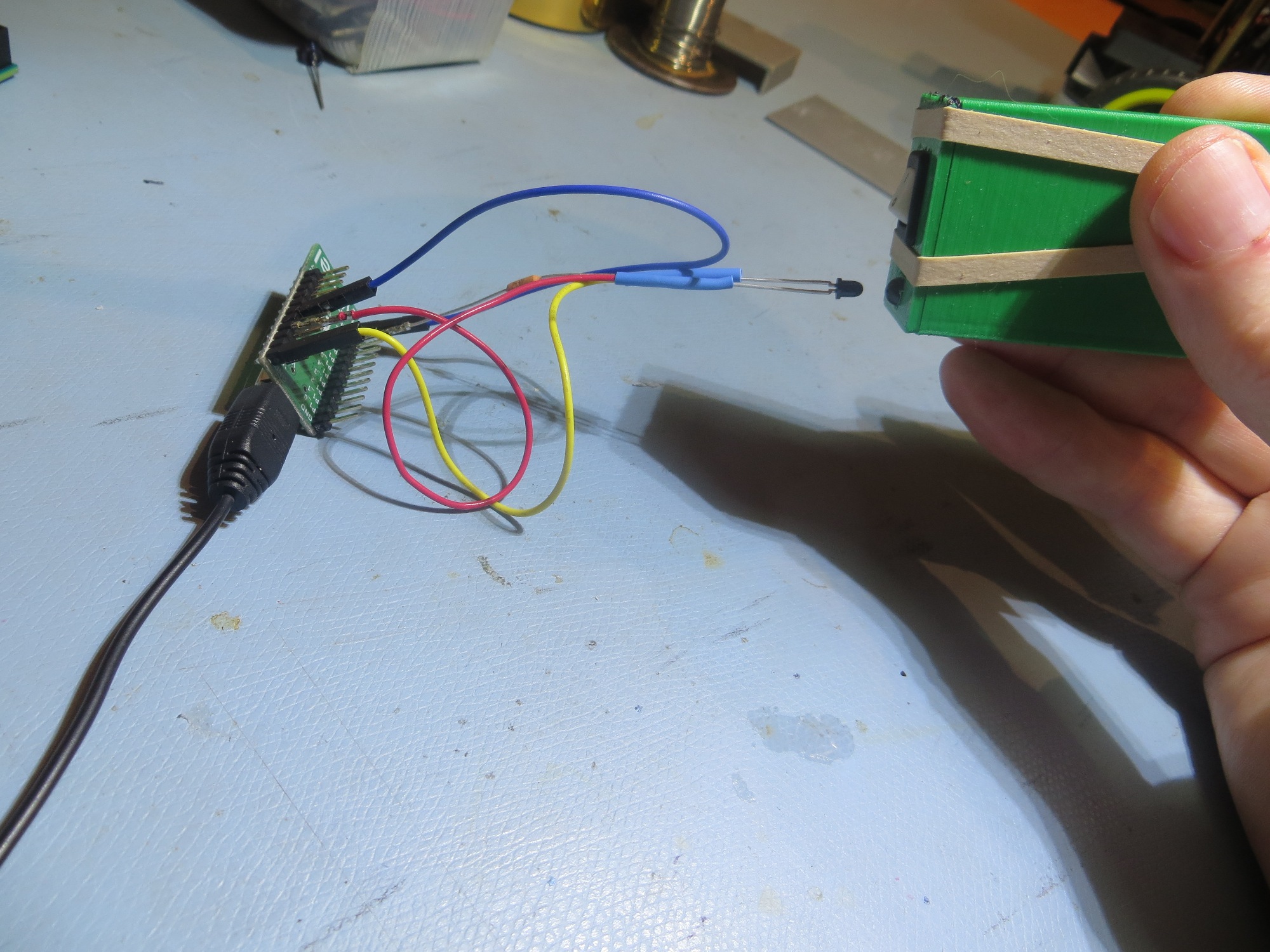
A couple of quick bench-top tests convinced me I was on the right track; At 1m separation between the IR LED/reflector combination and the robot, I was able to drive the robot’s phototransistors into saturation (i.e. an analog input reading of about 20 out of 1024 max), where before I was lucky to get it down to 100 or so. However, this only happened when I got the LED positioned at the reflector focal point, which was tricky to do by hand, but not too bad for a first try!
Next, I tried incorporating the reflector idea into the current charging station IR LED/charging probe fixture, as shown in the following photo. This was much closer to what I wanted, but it still was too difficult to get the IR LED positioned correctly, and this was made even more difficult by the fact that I literally could not see what I was doing – it’s IR after all!
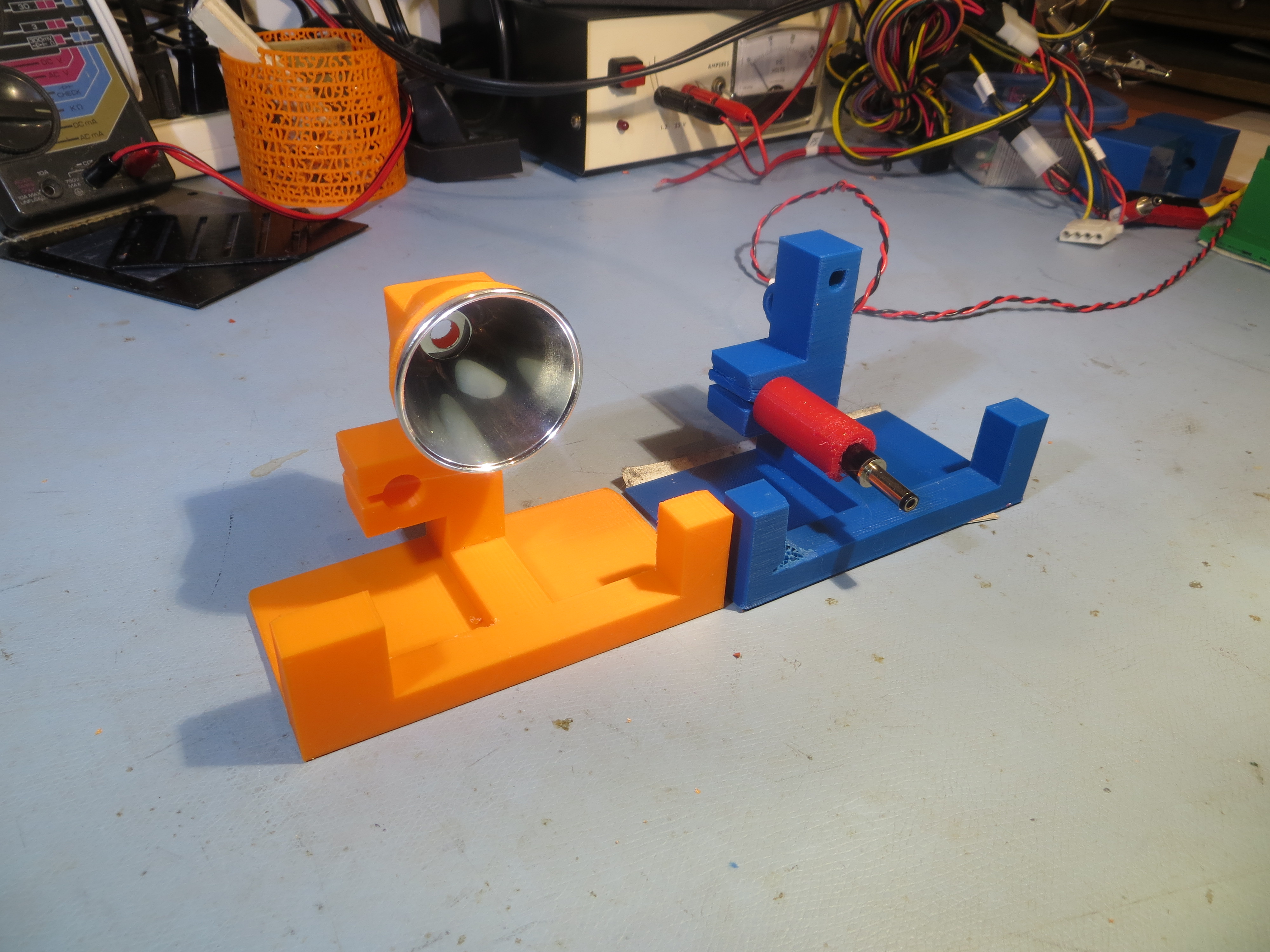
New reflector and old charging station fixture designs
However, the reflector focusing performance should be (mostly) the same for IR and visible wavelengths, so I should be able to use a visible-wavelength LED for initial testing, at least. So, I set up a small white screen 15-20 cm away from the reflector, and used a regular visible LED to investigate focus point position effects. As the following photos show, the reflector makes quite a difference in energy density.
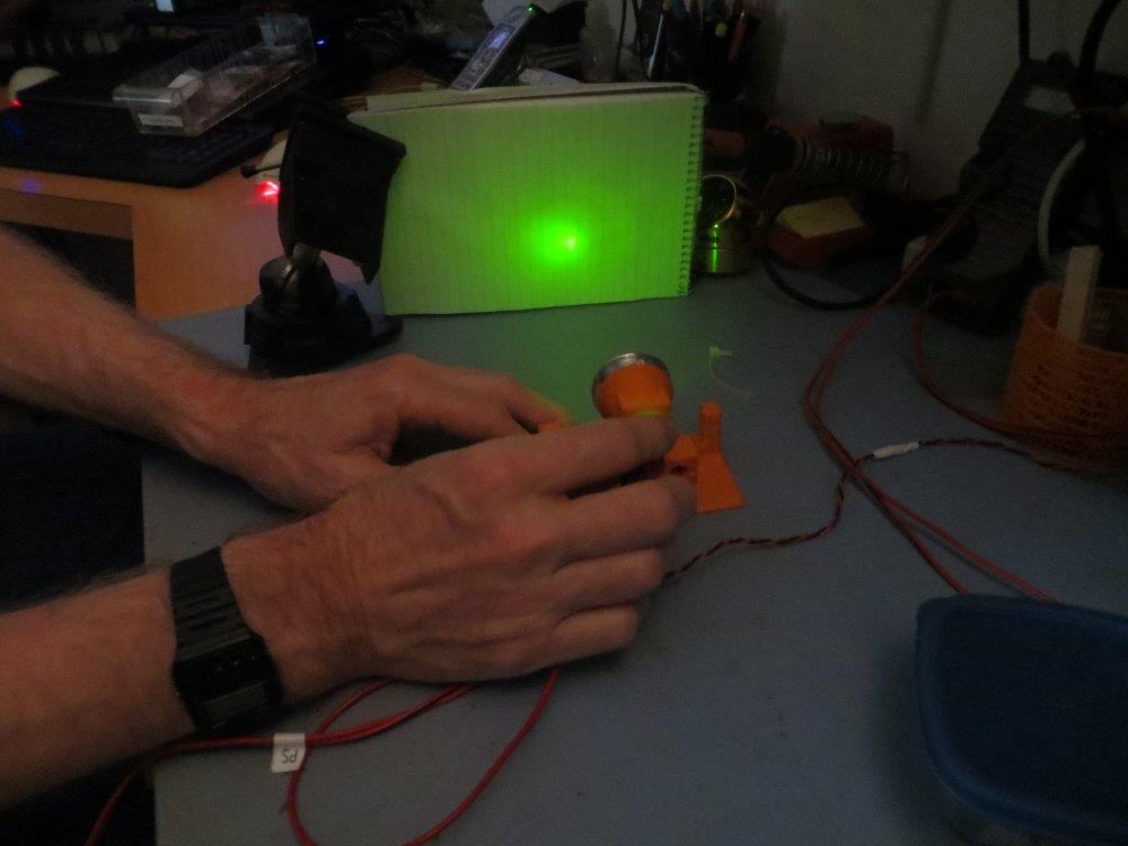
Green visible LED, hand-positioned near the focal point
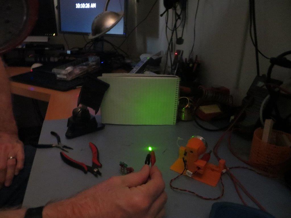
Pattern without the reflector
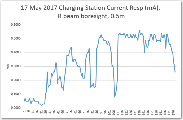
Next, I used my Canon PowerShot SX260HS digital camera as an IR visualizer so I could see the IR beam pattern. As shown below, the reflector does an excellent job of focusing the available IR energy into a tight beam
IR beam visualized using my Canon PowerShot SX260HS digital camera
IR LED, without reflector
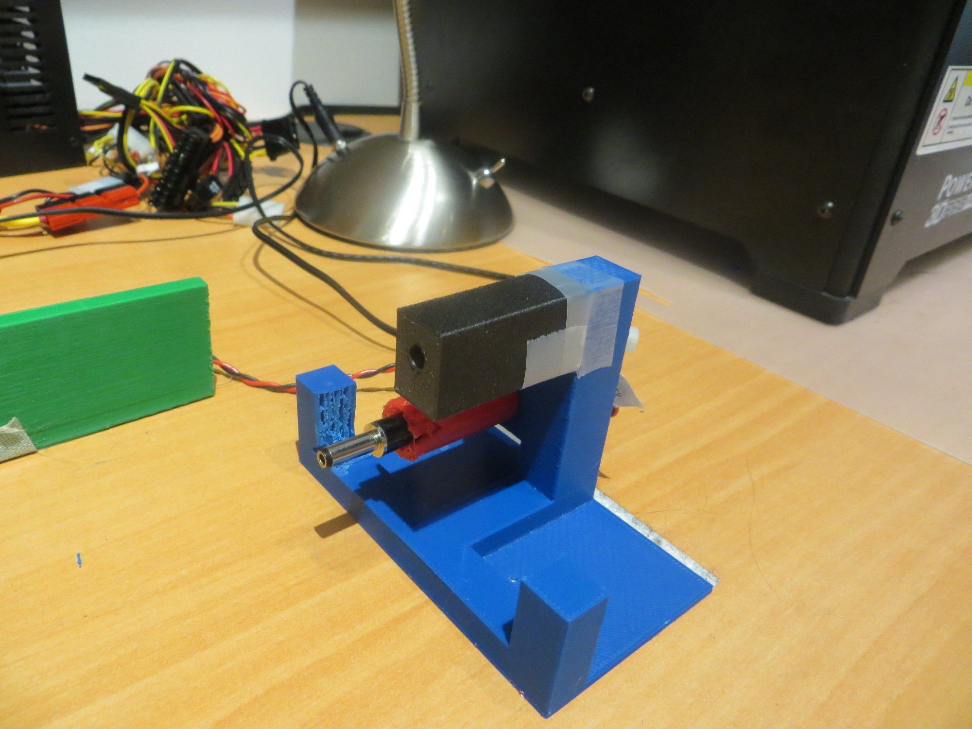
Next, I made another version of the reflector holder, but this time with a way of mounting the LED more firmly at (or as near as I could eyeball) the reflector focal point.
Reflector holder modified for more accurate LED mounting
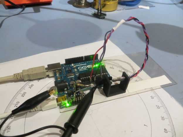
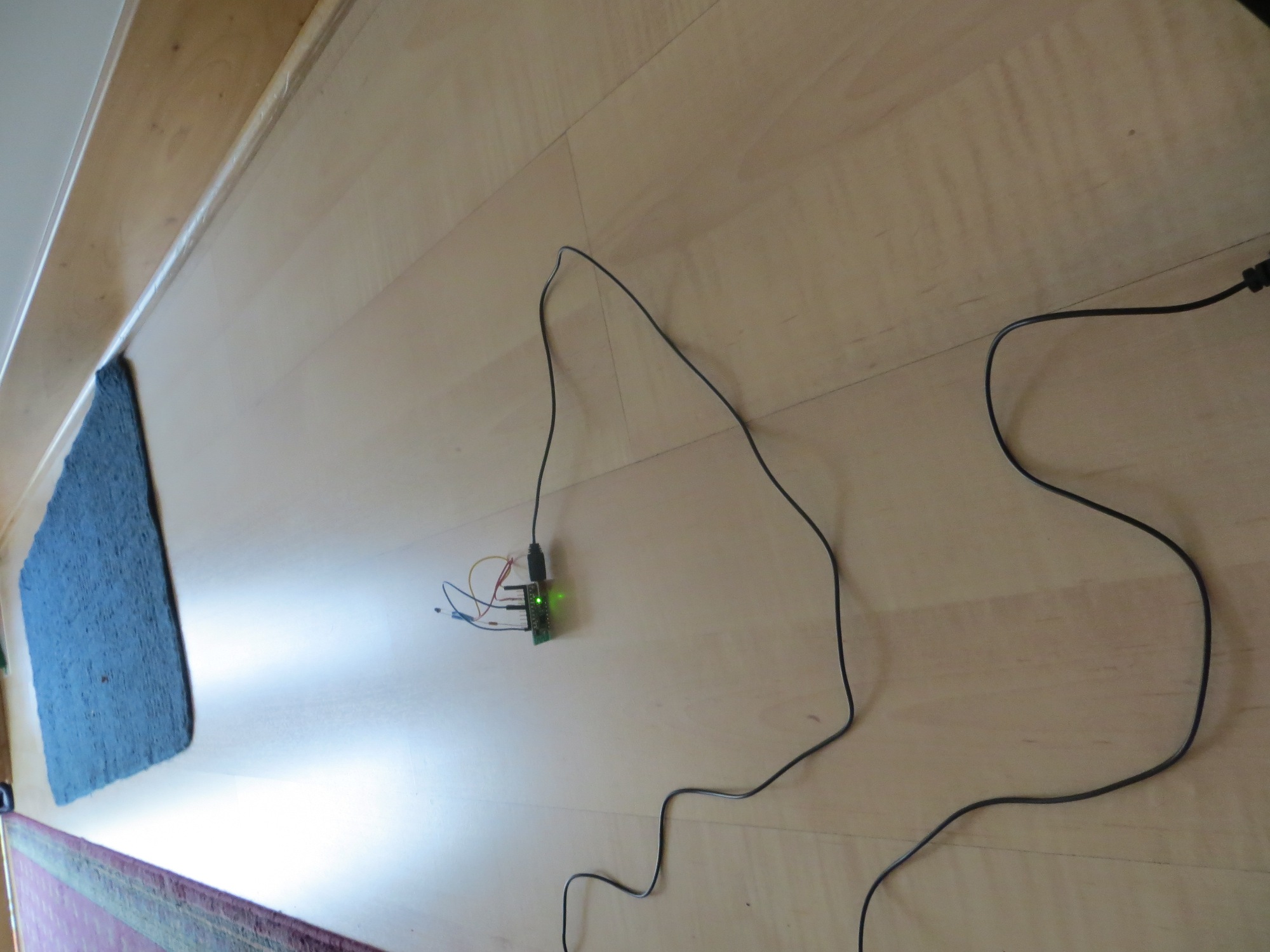
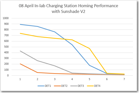
With this modification, I was able to get pretty good focusing without having to fiddle with the LED location, so I set up some range tests on the floor of my lab. With LED overhead lighting (not incandescent), I was able to get excellent homing performance all the way out to 2m, as shown in the following photos and plots
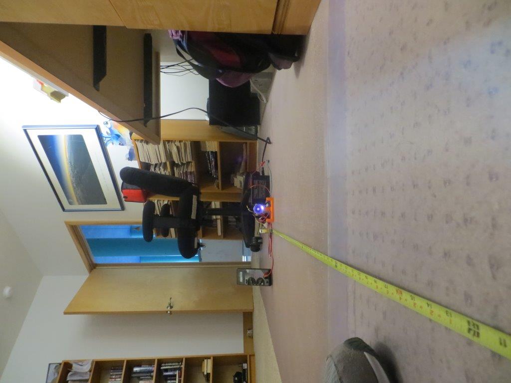
Range testing the IR reflector in the lab. Distance 2m
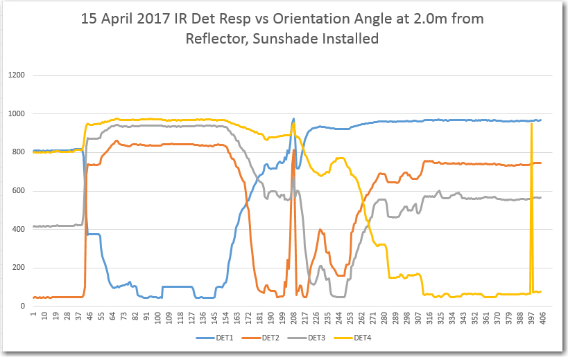
IR Detector response vs orientation at 2m from reflector, in the lab
IR reflector beam pattern at 2m, visualized using digital CCD camera
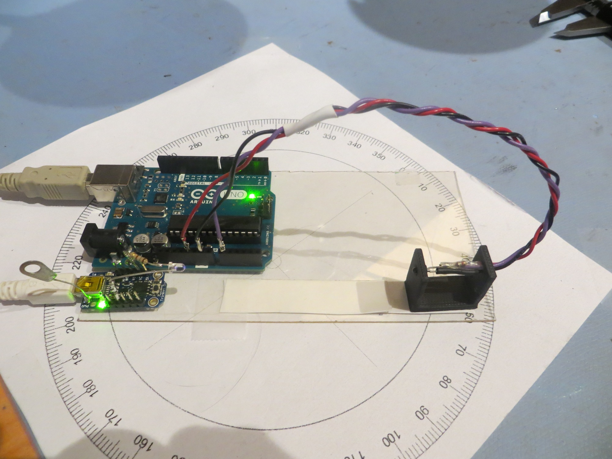
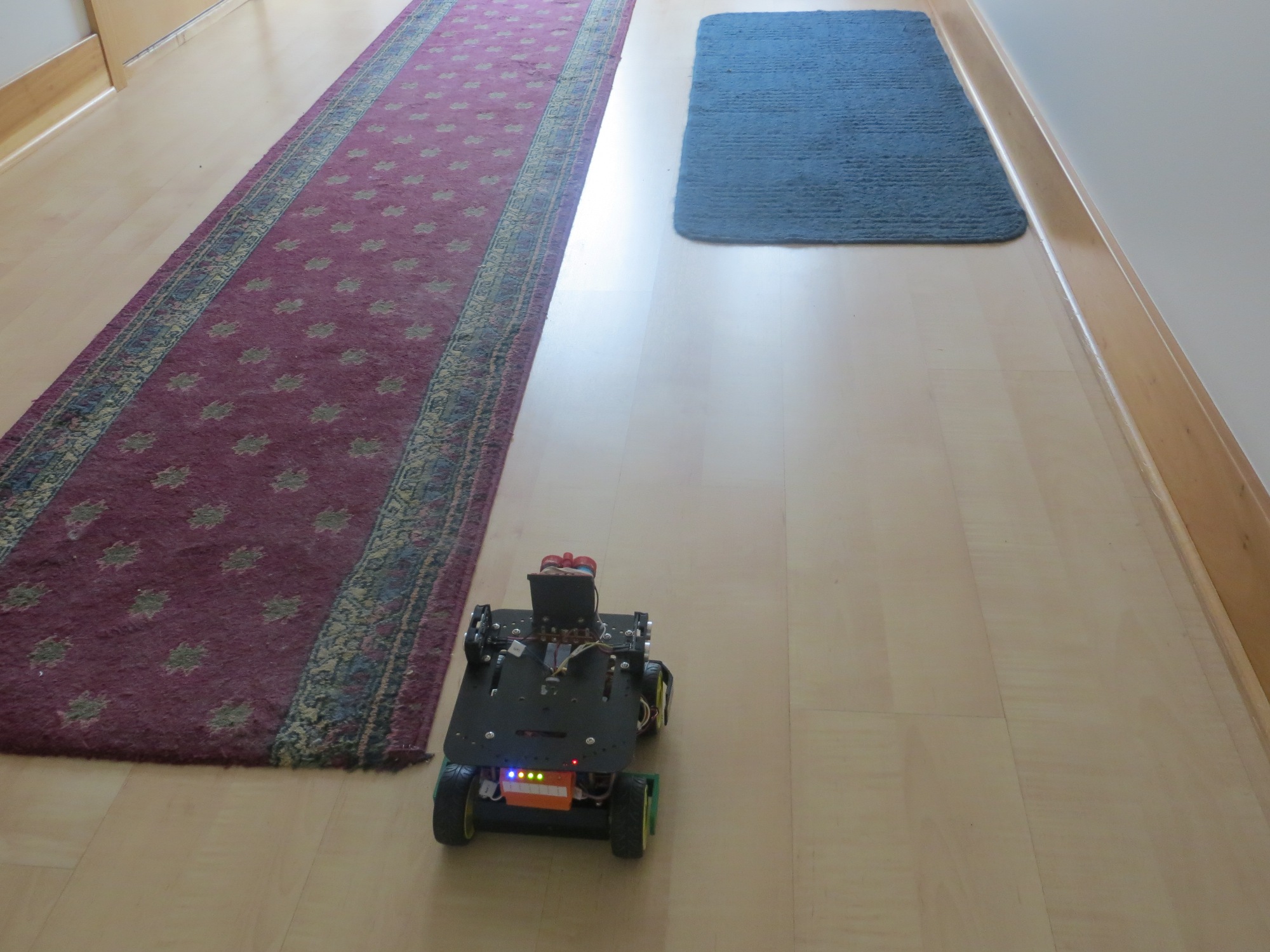
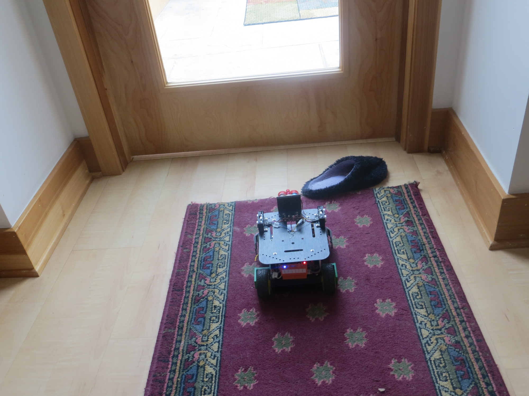
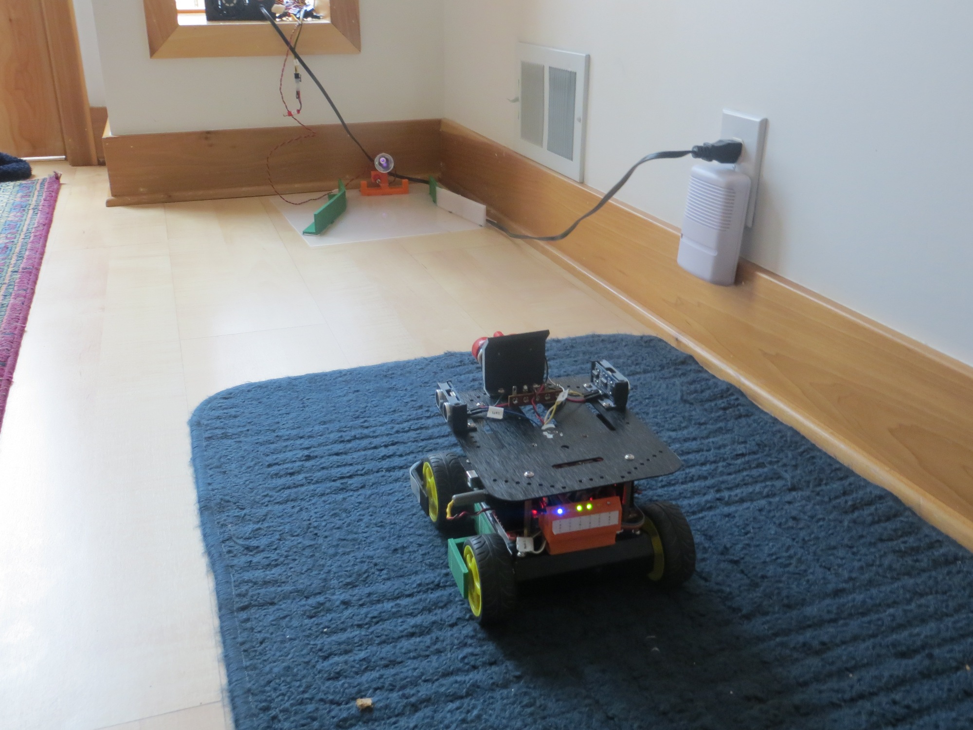
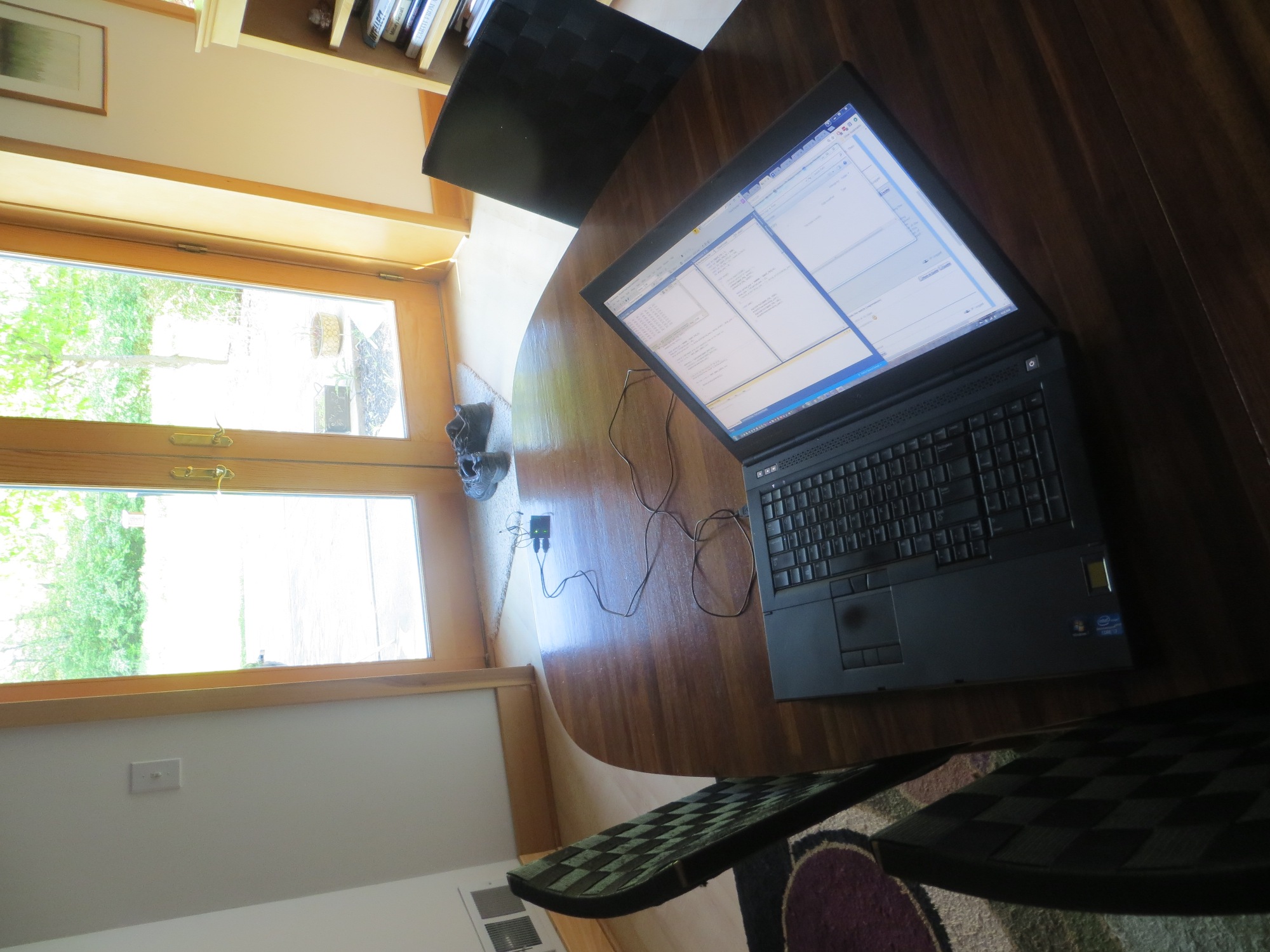
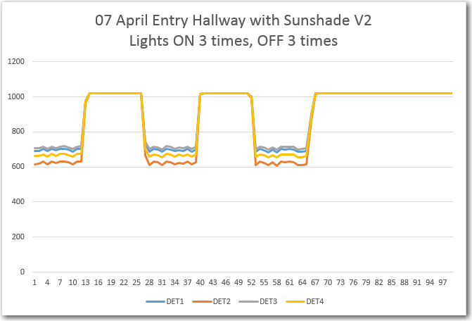
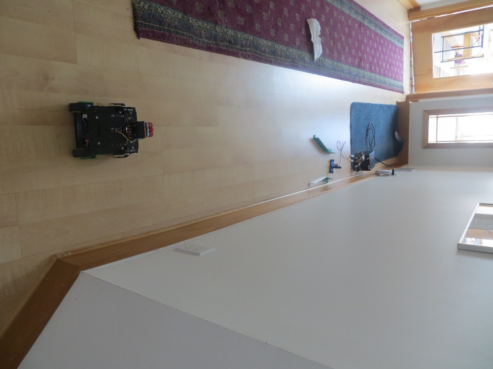
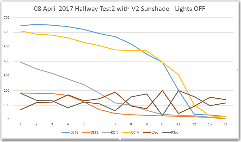
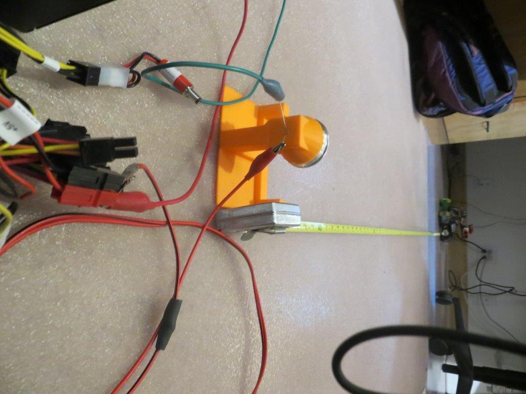
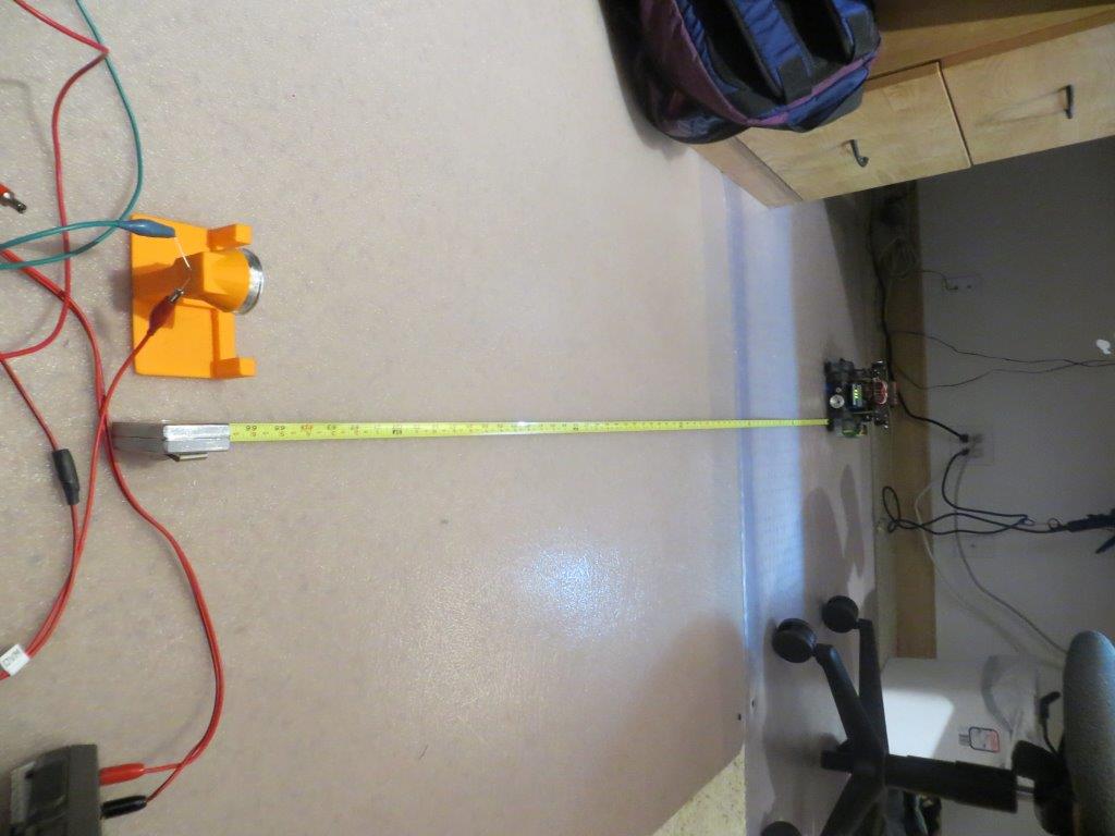
After this, I decided to try my luck again out in our entry hallway, with the dreaded IR interference from the overhead lighting and/or sunlight. I installed the lead-in rails in the ’tilted’ arrangement, and then performed a response vs orientation test with the robot situated about 2.5m from the IR LED/reflector assembly, in natural daylight illumination with the overhead incandescents OFF. This produced the curves shown in the plot below.
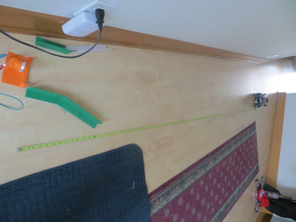
Robot response vs orientation test setup, 2.5 m from tilted lead-in rails & LED/reflector assembly
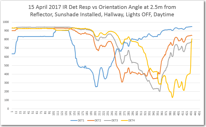
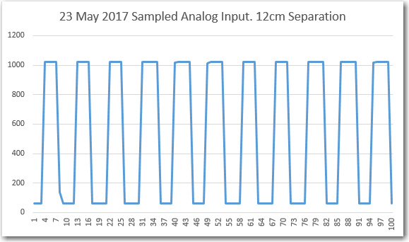
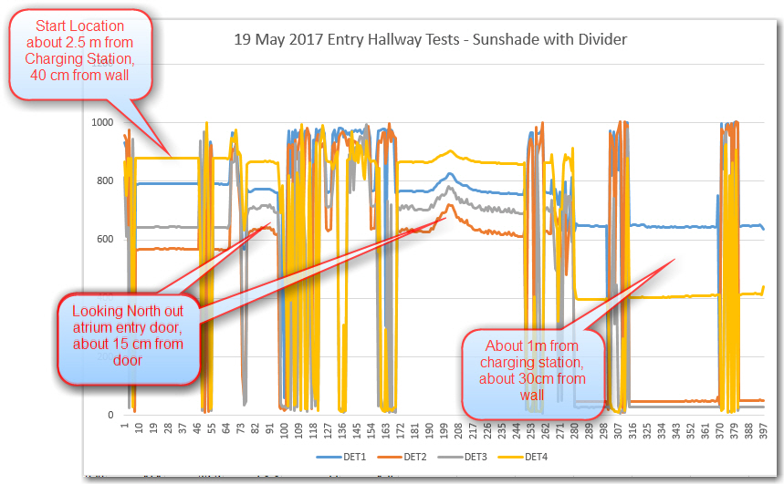
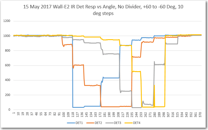
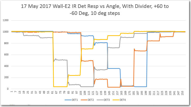
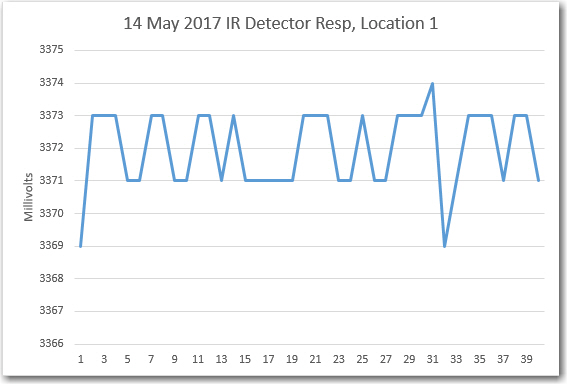
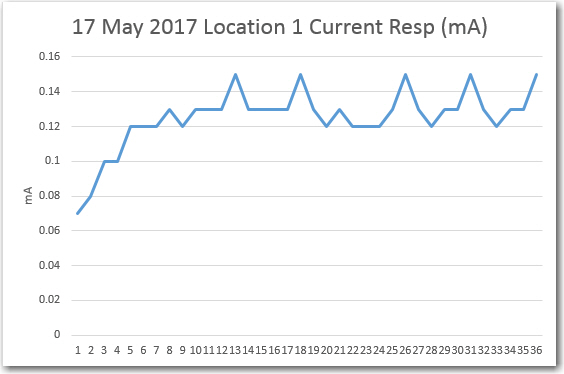
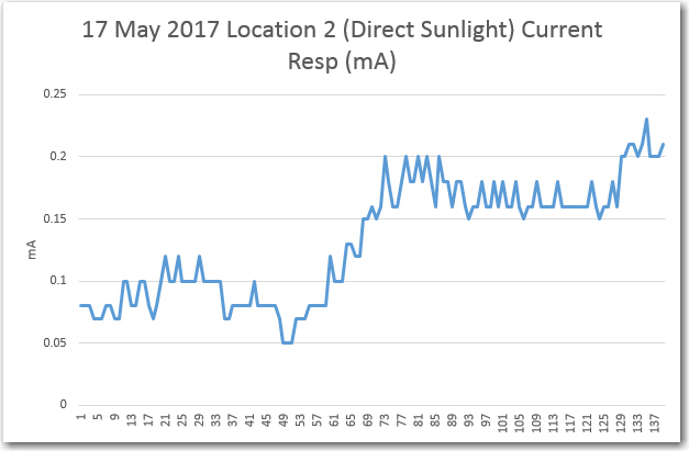
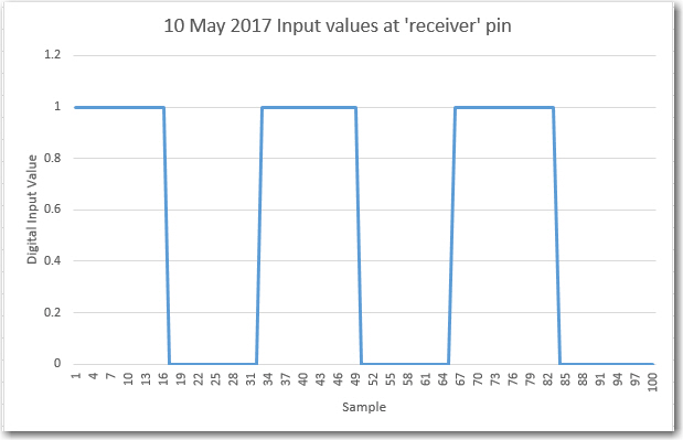
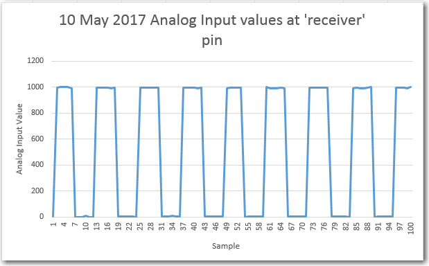
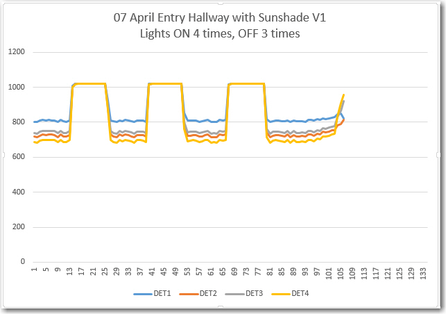
IR detector response vs orientation test, 2.5 m from IR LED/Reflector assembly
In the above Excel plot, the individual detector response minimums can be clearly seen, with minimum values in the 200-300 range, and off-axis responses in the 800-1000 range. This should be more than enough for successful IR homing.
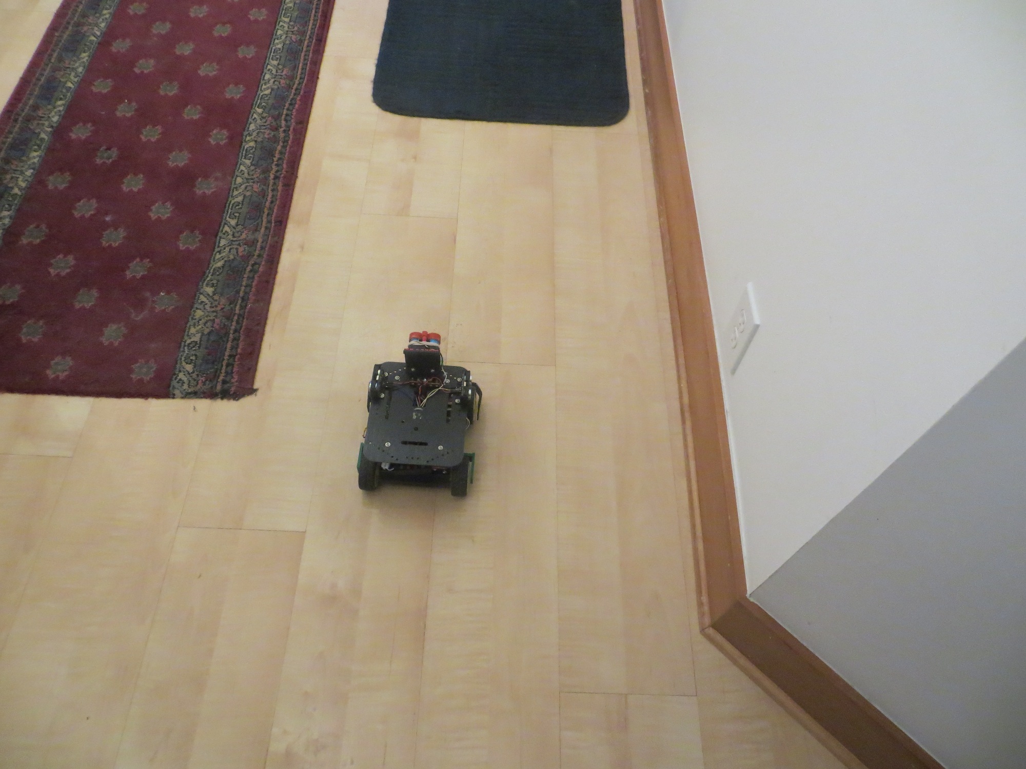
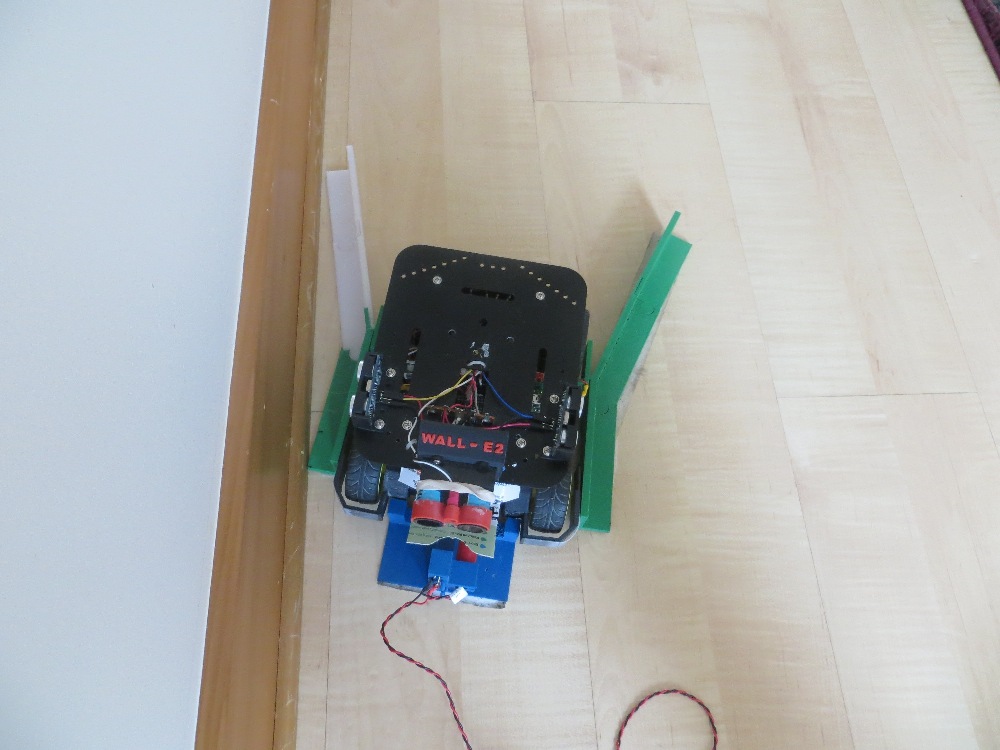
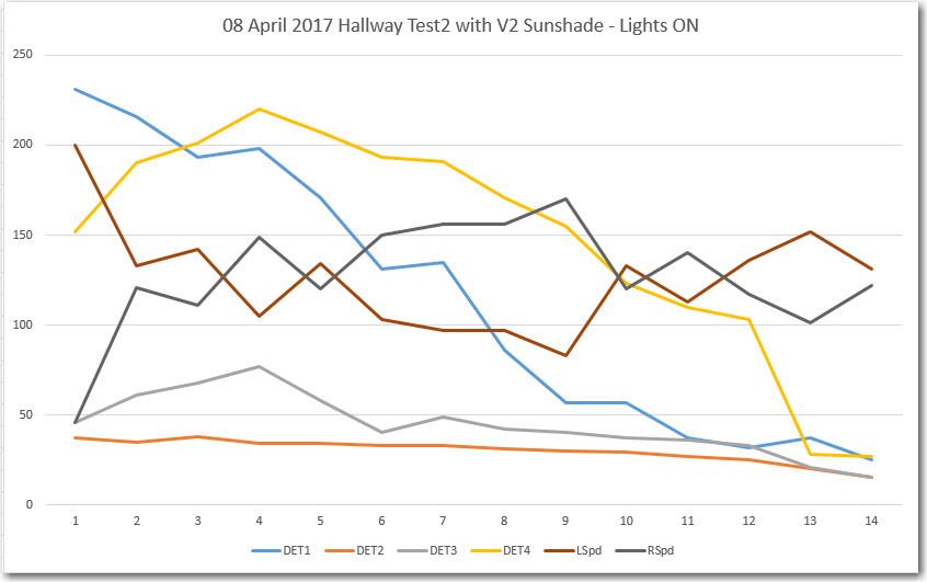
After seeing these positive responses, I ran some homing tests starting from this same general position. In each run, the robot started off tracking the right-hand wall at about 50 cm offset. One run was in daylight with the overhead lights OFF, and another was in daylight with the overhead lights ON. As can be seen in the videos below.
Both of the above test runs were successful. The robot started homing on the IR beam almost immediately, and was successfully captured by the lead-in rails.
So, it is clear the reflector idea is a winner – it allows the robot to detect and home in on the IR beam from far enough away to not miss the capture aperture, even in the presence of IR interference from daylight and/or overhead incandescent lighting.
Next step – reprint the IR LED reflector holder with the charging probe holder included (I managed to leave it out of the model the last time), and verify that the robot will indeed connect and start charging.