Tag Archives: PID

Charging Station Design, Part XIII – More PID Tuning

Posted 28 March 2017

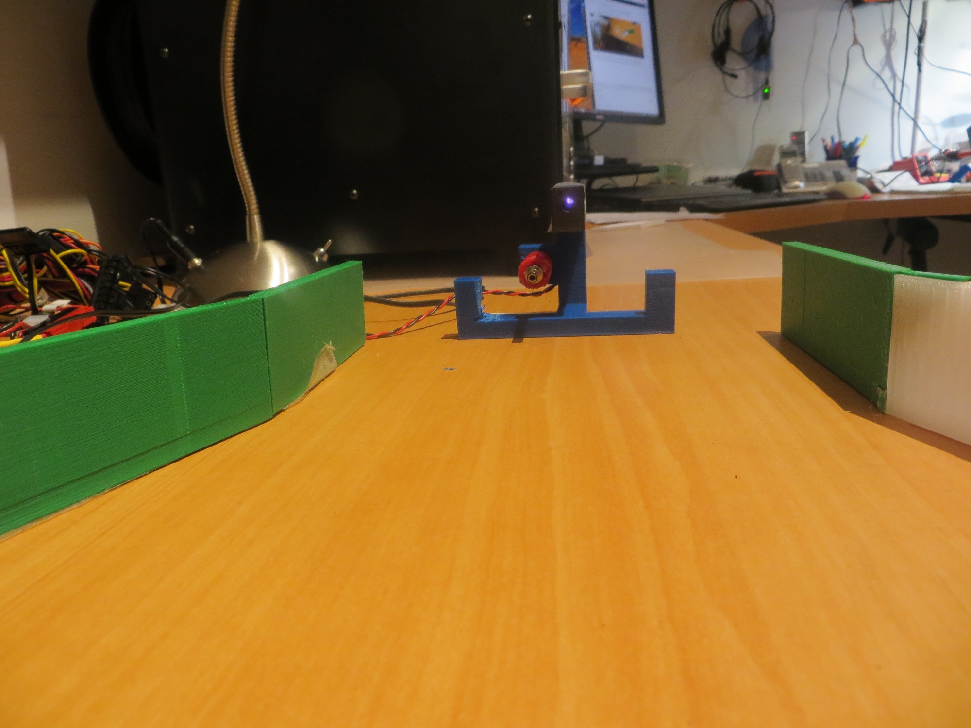
After my cleanup-and-label campaign documented in my last post, I was ready to get back to PID tuning for homing in on the charging station.  When my grandson was here, he pretty much took over my primary work area, so I was forced to move my bench-top testing range to another part of my bench.  This was not quite as convenient for reprogramming the bot, but it did give me a bit more distance between the initial bot position and the IR LED in the charging station, as shown in the following photo
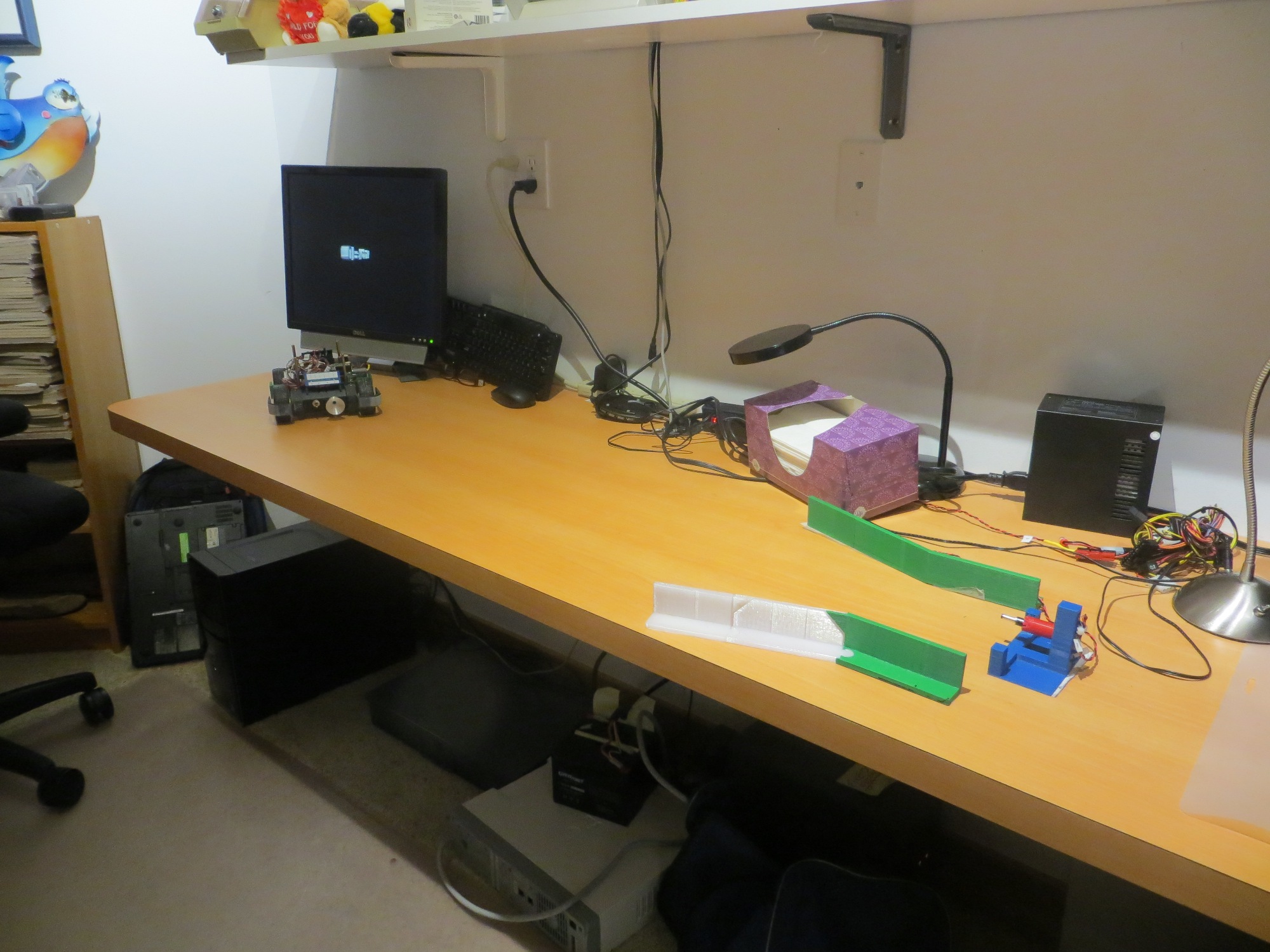
Wall-E2’s new PID test range

I started out by going back to the simplest possible PID setup – namely (p,i,d) = (1,0,0) and ran a series of range tests, as shown in the following video.

As is evident in the video, Wall-E2 has no difficulty homing into the charging station when initially placed near the edge of the bench, but won’t home properly from the other side.  After thinking about this for a bit, I came to the conclusion that the reason for this is that the center of the charging station is physically located near the edge of the bench, so when the bot starts at that edge, it is actually close to the centerline of the charging station, and therefore is almost perfectly lined up at the start. When starting from the other side however, the initial position is not lined up with the charging station centerline and therefore has to make more of a correction to get lined up.  From this I hypothesized that the PID setting of (1,0,0) doesn’t provide enough of a wheel-speed correction to make the required turn.

So, next I tried a PID of (2,0,0), and this worked much better, as shown in the following video

As can be seen from the first run above, the robot is doing a much better job of homing, but unfortunately ran into the left side rail instead of being captured.  This turns out not to be a PID tuning issue, but rather a problem with the IR beacon pattern relative to the lead-in rail arrangement.  The line from the robot’s starting position to the IR LED unfortunately intersected the outside of left lead-in rail instead of the inside.

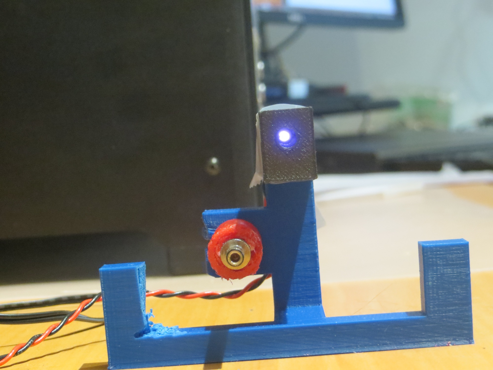
As an experiment to confirm the IR beam pattern hypothesis, I printed up an auxiliary part to restrict (not collimate, as that implies shaping) the beam to a narrower pattern, as shown in the following photos  ( taken with a digital camera with a wavelength range that covers the  IR wavelength being used)
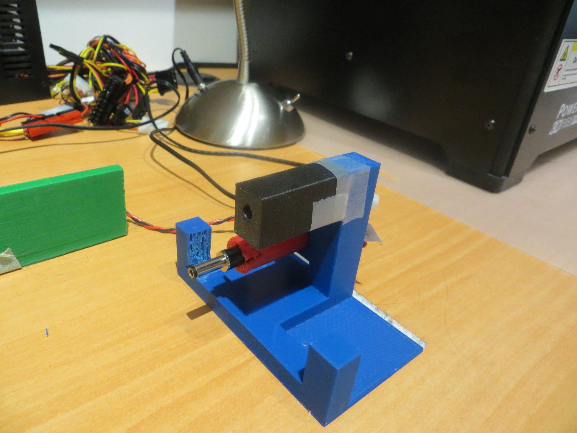
This experiment ‘worked’ in the sense that it showed that the IR beam was no longer visible outside the lead-in rail aperture, but it also made it so narrow that the robot had to be right on the centerline to sense the IR beam at all.  Although this solves the problem of hitting the rail, it would make it very difficult for the robot to ever find the charging station in the first place when approaching at the typical wall-following standoff distance.

So, although I plan to do a bit more fine-tuning of the PID parameters, it appears that the basic homing problem is solved,  but the challenge now is  getting the robot into a position where it can home in on the IR beam without running into a side rail.  The current wall-following algorithm doesn’t have a set stand-off distance, so the robot may be ‘cruising’ at anywhere from 10-70 cm from the wall being tracked.  Assuming that one lead-in rail is against the wall, the IR led is located about 20 cm out, and the front end of the outside lead-in rail is about 35 cm out.  When the robot is just captured by the outside rail, its centerline is about 16 cm out.  The angle from the IR LED to the center of the robot at this point is about 11-12 º.  So, assuming the robot is wall-following and at some point intersects the IR beam and starts homing, the angle from the robot to the IR LED has to be less than 11-12 º or the robot will not be captured by the lead-in rails.  The situation is shown graphically in the following diagram.
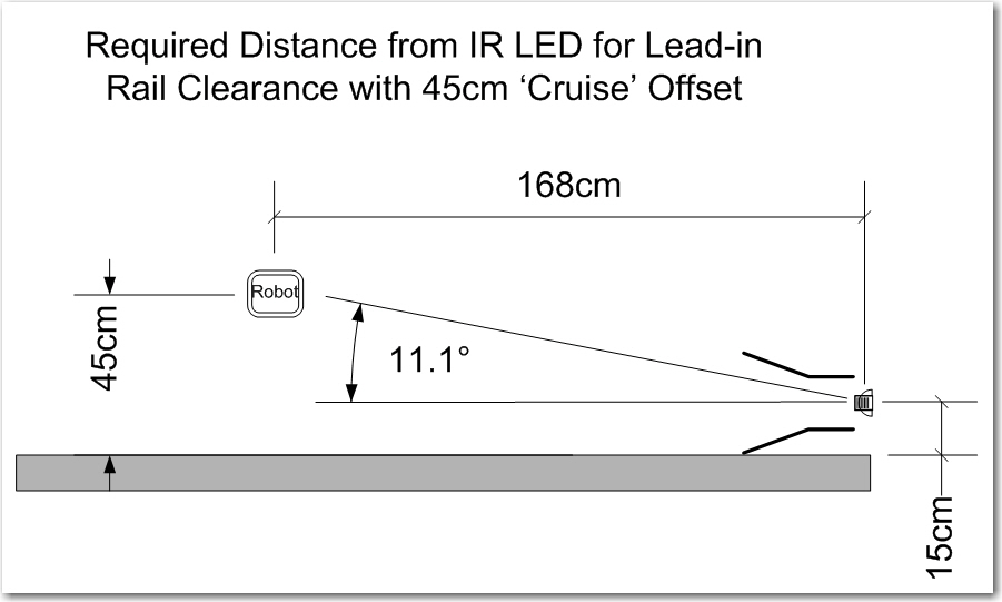
Capture parameters for the robot approaching a charging station

As shown above, if the robot is ‘cruising’ at 45 cm from the wall, then it has to start homing from no less than 1.7 m or so from the charging station in order to get captured by the lead-in rails.  This is  a large, but impossible distance.  The robot can currently home from about 1 m out, so getting out to 1.7 m might be as easy as increasing the IR LED current;   it is  currently running at about 30 mA, and it is rated for 100.

Another possibility is to angle the capture gate out slightly with respect to the wall. There’s no real reason the charging station rails need to be parallel to the wall – it’s just my neat-freak mentality that makes me do things that way.  If I angle it such that the inside lead-in rail touches the wall at both its forward and trailing ends, that will angle the beam out at about 13 º, and move the minimum capture distance in to about 1.0 m, as shown in the following diagram.  1.0 m is just about where the robot is capturing now – yay!!
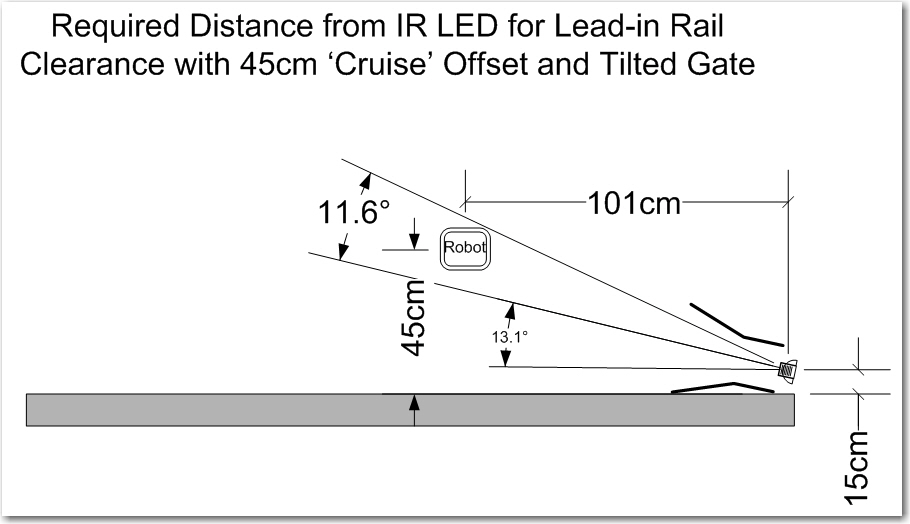
Tilted gate option. The tilt decreases the minimum required IR beam capture distance from about 1.7m to about 1.0m

So, it appears that tilting the capture gate is the way to go; this doesn’t cost anything but a slight ding in my ‘neat-freak’ index, and should  eliminate or greatly reduce problems with charging station capture failures.

Stay tuned,

Frank
 

Charging Station Design, Part XII – A Pause to Clean Up

Posted 22 March 2017

This last weekend was devoted to a whirlwind visit by the St. Louis family, which includes my 13-year old, growing-like-a-weed, 3D printing enthusiast grandson.  So, I didn’t get a whole lot of time to work on Wall-E2’s problems, as Danny basically took over my entire lab ;-).  So, now that the horde (can one 13 year-old kid constitute a ‘horde’?) has departed, I can get back to some sort of normalcy and make some progress.

At the end of my last post on this subject, I had concluded that I needed to go back and verify the details of the IR homing hardware and software, as the results I was getting didn’t make sense.  So, I set up some experiments where I could carefully watch the raw output from all 4 IR detectors, and the changes from physically blocking one IR LED at a time.  This experiment convinced me that something was definitely wrong with the hardware; at least one detector appeared to be dead, and it also looked like blocking one detector affected the outputs of more than one – strange!

So, back to the hardware; After dismounting the combined charge status display panel/IR detector module and separating the two, and physically inspecting the IR detector module I  found  a bad solder joint (what – a bad solder joint!?  I  never make bad solder joints! – must have been someone else!) on one of the detector connections to the interface  header.

After repairing the bad solder joint, I carefully worked my way through the cabling maze on Wall-E2 to the microcontroller end of the IR detector cable, to verify proper connection on that end.  The connections looked good, so I did some more testing, only to find that one of the IR detector outputs appeared to be dead – it’s analog reading stayed around 4-500 no matter what I did.  Some more physical inspection revealed the problem – my 4-pin IR detector cable was connected to A2-A6 on the Mega board, but I was reading A1-A5, so the A1 input was essentially ‘open-circuit’ – oops!

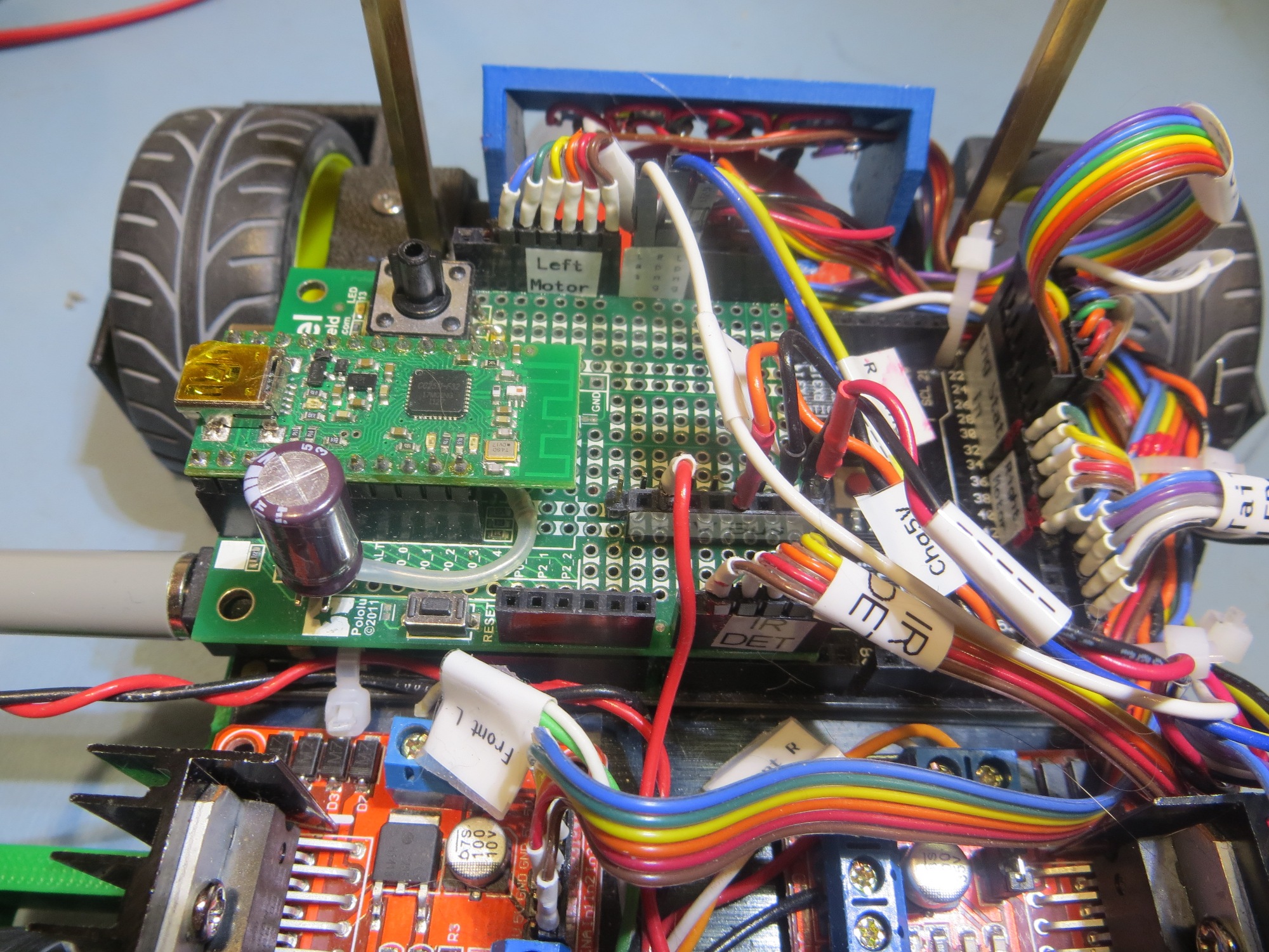
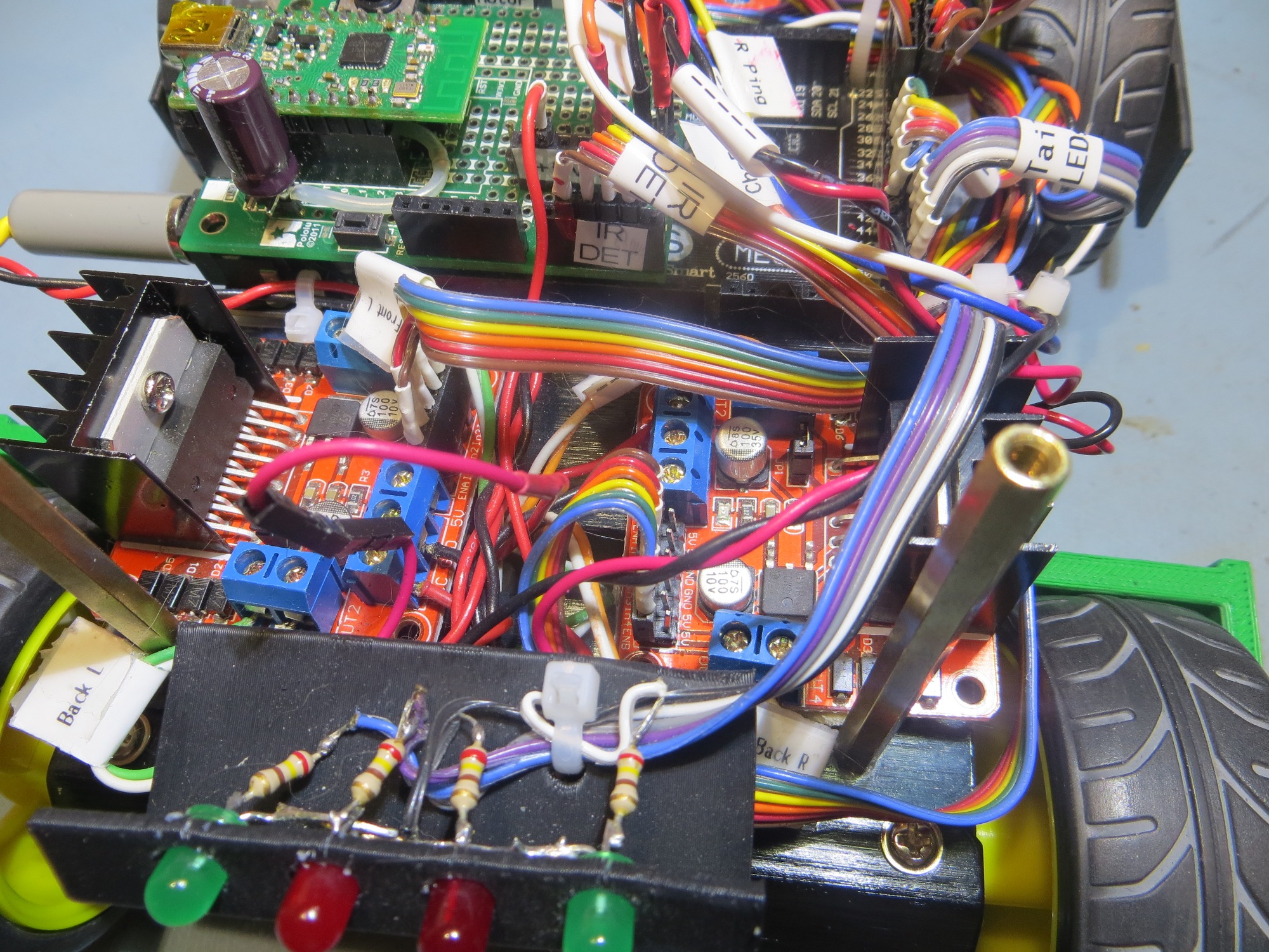
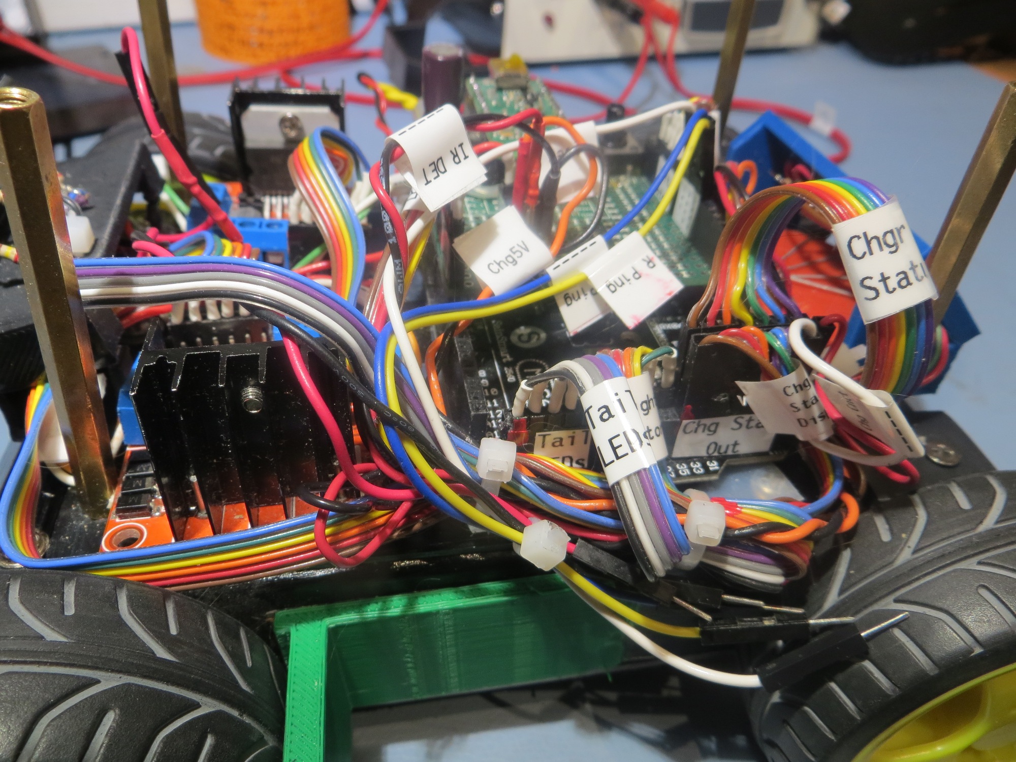
After fixing this booboo, things started to perk up and act a *lot* more normally! ;-).  However, instead of immediately going back to testing mode, I decided that I needed to get serious about labeling and indexing cables (I use red fingernail polish to index one end of each connector to the corresponding microcontroller pin) and connectors  on Wall-E2, so I would have less trouble in the future with the large number of ribbon cables and loose wires now festooning the robot.   Fortunately I have my wonderful Brother P-touch label maker to help me with this task. As an aside, if you are a ‘maker’ hobbyist like myself, a label maker is an absolute godsend, and I can’t recommend the Brother P-touch highly enough.

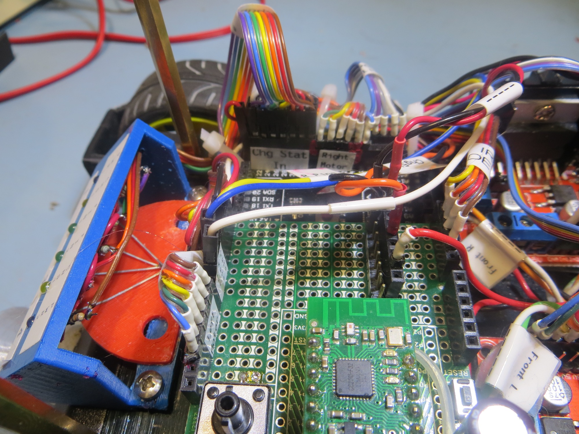
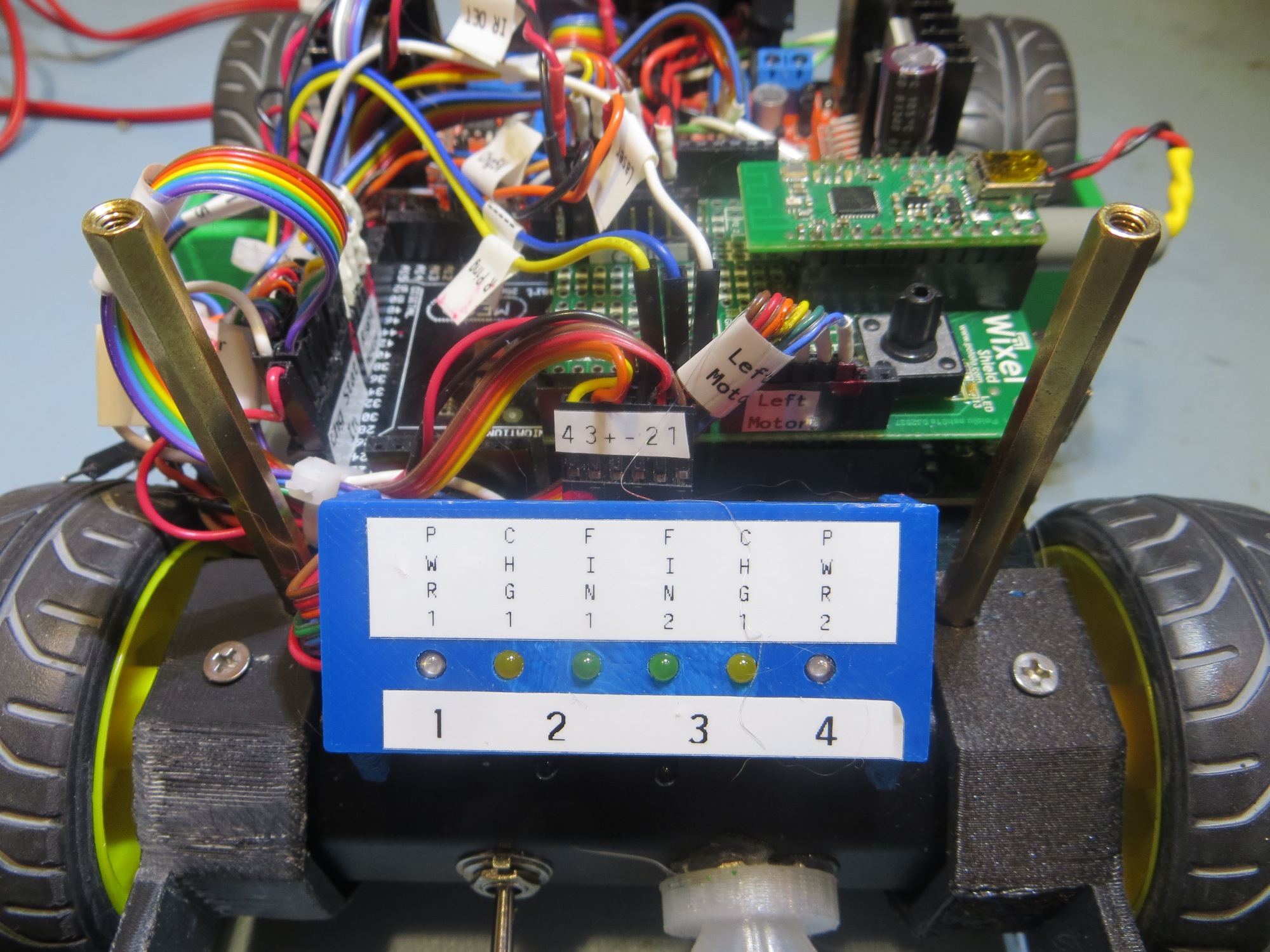
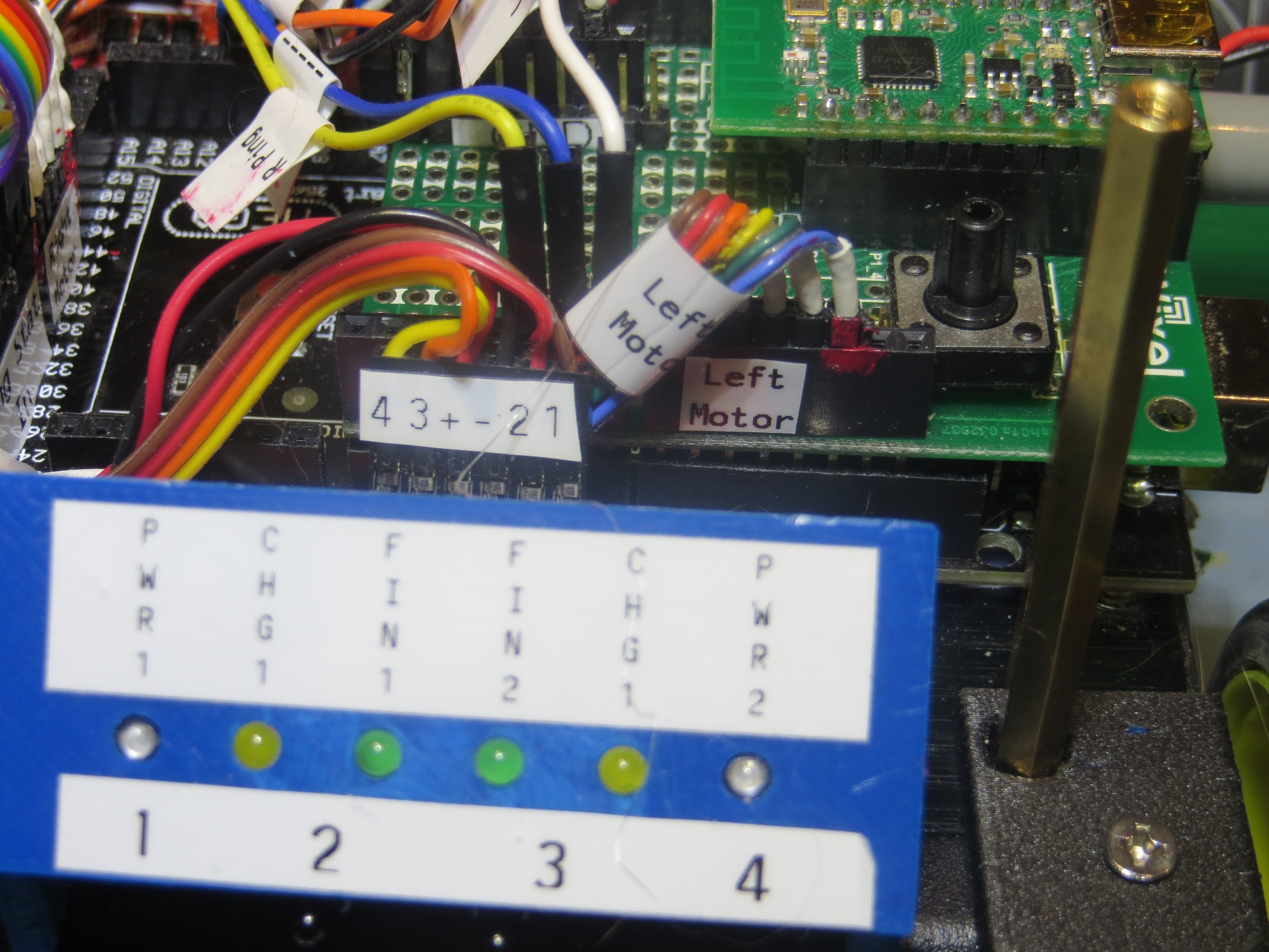
After my labeling and cleanup campaign, Wall-E2 is  a lot more self-documenting, as shown in the following photos

Charging Station Design, Part XI – PID Tuning

Posted 14 March 2017

As I was doing the IR homing tests described in my last post, I noted that Wall-E2 wasn’t all that great at homing; in particular it missed the opening in the lead-in rails on several occasions, instead hanging up on one side or another.  This was a bit mystifying to me, as I thought I had the homing code working very well with my old 3-wheel robot (see ‘IR Light Follower for Wall-E2, Part X – More PID Tuning‘).  At the time, I decided to use one of my best scientific research tools and simply ignore the problem, hoping it would either go away, or my subconscious mind (by far smarter than my conscious one!) would figure it out in the shower or while drifting off to sleep.

And, in fact, last night while drifting off to sleep, I remembered that the PID tuning for the 3-wheel robot had to take into account the fact that  even small  differences in drive wheel speeds get magnified by the free-castering front wheel.  Wall-E2, with its all-wheel drive  behaves entirely differently, and since small wheel speed differences don’t get amplified into big directional changes, the PID tuning parameters appropriate for the 3-wheel version are too passive for the 4-wheel one.

So, I went back to the drawing board (again!) for PID tuning for the 4WD Wall-E2, starting with the current 3-wheel parameters as the ‘too passive’ baseline.  From my previous article, the final PID parameters were P = 0.1, I = 10, D = 0.2, with the input scaled by 1, 5, or 10 depending on IR beam signal strength.  My initial thought is that the 4WD robot needs a lot more ‘D’ (differential) to increase its turn rate with respect to IR beam heading changes, so I tried a couple of runs with the D value increased from 0.2 to 2 (factor of 10 increase).  As the following video shows, this did seems to increase Wall-E2’s agility somewhat, but still not enough to overcome even minor initial heading offsets, especially to the left.

After some more testing with different values of P,I,D, I began to wonder if I might be having problems with the basic IR detection hardware and homing software, independent of the PID tuning issue.  When I did the previous PID study, I also captured the raw detector data, which allowed me to determine how the PID tuning and the basic detection hardware/software were interacting.  I may have to go back and do that again with the 4WD setup

Stay tuned,

Frank


IR Light Follower for Wall-E2, Part X. More PID Tuning

Posted 19 November 2016

Well, as usual, things aren’t quite as simple as they seem, and the ’10 minutes, tops’ rule still applies (whenever someone says ’10 minutes, tops’, they are lying by  at least one order of magnitude!).  But, on the bright side, I really do understand PID control systems a lot better now (a low bar, as just the other day couldn’t remember what the ‘P’ in ‘PID’ stood for!), and I now think that WallE (and/or WallE2) has  a pretty reasonable chance of homing in on an IR beacon with sufficient accuracy to be captured by a charging station setup.

In my last post on PID tuning, I had assumed that the PID compute engine normalized the tuning constants before doing the computation, and I decided I needed to check that assumption before continuing.  When I looked into the actual code in the Arduino PID library, I found that this was  not true – the PID compute engine does not normalize.  It simply computes the PID expression:

output = kp * error + ITerm- kd * dInput;

where ITerm is  ITerm+= (ki * error)

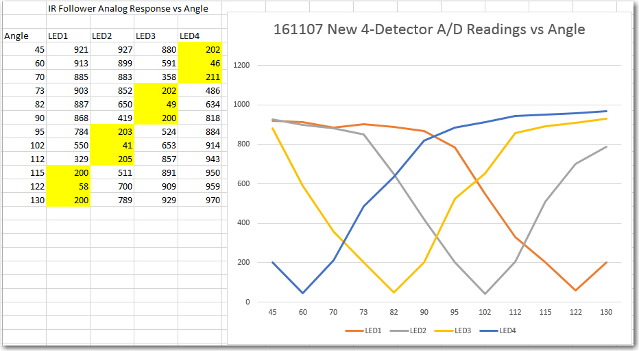
However, what this means is that my previous attempts to simplify the tuning problem by eliminating the I and D terms and just tuning the P term was doomed to failure – there was no way ‘do just P’ because the physical dynamics are too complex.  The response curves of the IR detectors (shown below),

4-detector heading test results

4-detector heading test results

combined with the physical dynamics of the robot itself, require more than just a proportional response to the error (the difference between the sums of the two left and two right detector readings)   term.  Ken suggested I could do this by using a pulse train (similar to PWM) for the motor drive signal, but I think that is equivalent to adding some ‘D’ to the PID tuning parameters.

In addition to the physical dynamics issues, there is also the problem of the detector response versus distance.  At maximum detection range, all detector readings are near 1000, so the error term is very small, on the order of 10-50.  However, as the robot gets closer to the emitter, that error term rapidly gets much larger, on the order of 500-900.  This means that the PID tuning parameters appropriate for the ‘far’ case will be wildly inappropriate for the near case (another consequence of not normalizing the PID values internally).

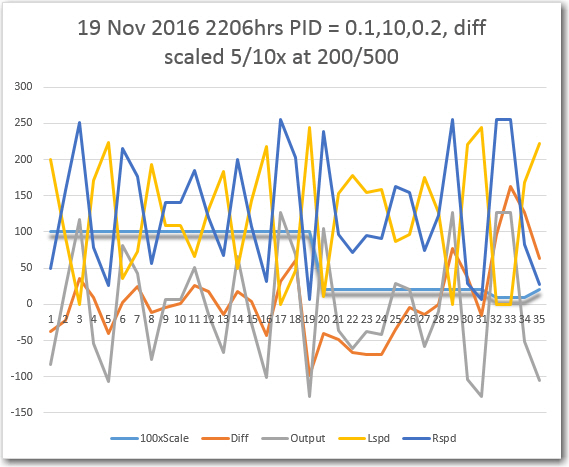
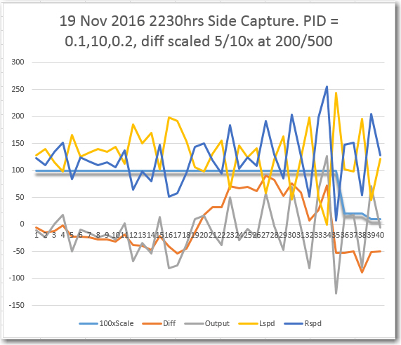
In any case, after a  loonnnggggg series of floor field tests, I think I have arrived at a reasonably effective homing algorithm.  Instead of trying to modify the PID tuning parameters as the robot approaches the emitter, I found it more effective to keep the PID tuning parameters constant, and instead scale the  PID input (error) signal in three steps; 1 (no scaling) for error term values below 200, 0.2 (divide by 5) for values between 200 & 500, and 0.1 (divide by 10) for values above 500.  A representative set of data and some videos are shown below.  The last video shows a ‘side capture’ scenario, where the robot approaches at right angles to the IR beam and successfully captures the beam and homes in on the emitter.

Typical run with 1/5/10x scaling as emitter is approaced

Typical run with 1/5/10x scaling as emitter is approached.  Scaling term is shown here at 100x for clarity

Side capture scenario. Scaling term is shown 100x for clarity

Side capture scenario. Scaling term is shown 100x for clarity


So, at this point I’m convinced that the PID/input scaling arrangement will work, and that I can get WallE2 to home in on an IR beacon.  The next challenge will be to integrate the IR homing function with the normal wall-following function, and to design/fabricate the charging station itself.  Stay tuned! ;-).

Frank


IR Light Follower for Wall-E2, Part IX – PID Tuning

Posted 16 November 2016

In my last post on this subject, I described by attempt to add PID control functionality to WallE’s IR light-following algorithm, and this is now looking pretty promising.  As an added bonus, I managed to suck my stepson Ken Frank, who graduated from Cornell with a MS in control theory, into helping me tune the PID controller. His first comment (well, the first comment after the obligatory “what have you gotten me into now, Ollie!”) was something like “you are over-controlling – you should simplify the problem and start with just ‘P’ – no ‘I’ or ‘D’. Then add P/I as necessary after getting the P value right.  Wish I had thought of that! ;-).

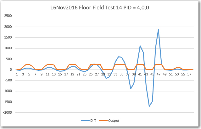
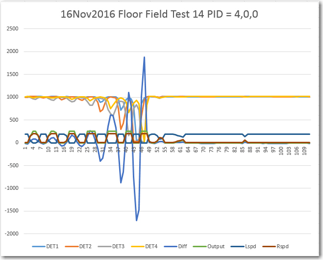
Anyway, I revised the code to do just that – with PID tuning parameters of 4,0,0 for both the far away and near cases, and re-ran my ‘floor range’ field test, as shown in the following video clip and plots.

Left/Right Differential (input to PID engine) and Output

Left/Right Differential (input to PID engine) and Output

All data from the run

All data from the run

More to follow…


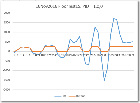
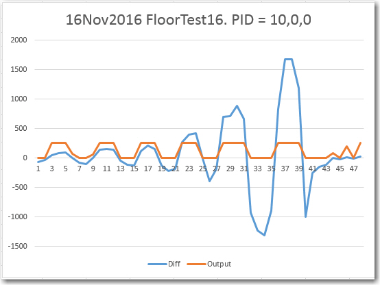
After taking the above video and data, it occurred to me that it was possible (although not very probable, IMHO), that the PID engine might not normalize the tuning parameters before computing the new output.  So, I ran two more tests – one with a PID of 1,0,0, and another with a PID of 10,0,0.  These tests, along with the ones for 4,0,0, should provide some insight into that question.  As can be seen from the plots, the tracking behavior for all three PID = X,0,0 conditions are pretty similar.  I also included a video clip of the PID = 1,0,0 condition.


161116_floorfieldtest15data 161116_floorfieldtest16data


More to follow

Frank


IR Light Follower for Wall-E2, Part VIII

Posted 13 November 2016

After reviewing the benchtop field test results, I decided to try implementing a PID (Proportional/Integral/Derivative) controller for WallE.  There is a quite nice PID library in the Arduino eco-system, thanks to Brett Beauregard (br3ttb@gmail.com), and  I already had it installed on my system from a previous project.  Getting it implemented for my project  wasn’t too much trouble, but of course  the issue with PID controllers is getting it ‘tuned’ (i.e. finding the values for P, I, & D) for the particular physical setup.

For my 4-detector system, I used the difference between the sum of the two left detector values  and the sum of the two right detector values as the input to the PID controller, and chose a setpoint of zero – i.e. the idea was to drive the difference in the detector sums to zero, which  should mean that the robot is pointed directly at the IR source.  The output from the controller was used in a differential fashion to drive the motors; the output was fed directly to the right motor driver as a 0-255 PWM value, and the left motor drive value was 255-Output.

The first  step was to set the PID values appropriately, and I had absolutely no idea how to do that –  so I just started with  the default values of 2, 5, and 1 for the P, I, and D values respectively, and DIRECT for the sense indicator.  Then I ran some tests on my 24″ benchtop range to see what happened.  Of course the first thing that happened is that WallE immediately departed from the plan and dove off the benchtop (I caught it before it hit the ground).  This was fixed by changing the PID output sense from ‘DIRECT’ to ‘REVERSE’, and I started getting some successful runs.

The next step was to make some more realistic homing tests, and for this I moved the IR emitter from my benchtop down to the floor at one end of my bench, and started WallE from the other end – about 1.5 m away.  I made a number of runs, changing the PID tuning parameters to try and find a reasonable arrangement.  After some playing around and some more Googling, I arrived at a tentative arrangement with a dual parameter set – one for small left/right differential excursions, and another for large excursions.  As  the following video shows, WallE successfully homed in on the IR emitter.

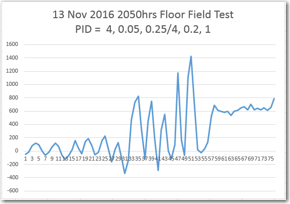
I also captured telemetry from the run, and plotted the left/right differential in Excel, as shown below:

Left/Right differential from 13 November floor field test

Left/Right differential from 13 November floor field test

In the above plot, a marked difference can be seen between the differential behavior up to about point 33, and the differential between 33 and the end of the run at about 55 (the data after 55 was captured after I stopped the robot and picked it up, and before I got it shut down). I believe this change is due to my use of two different values for I & D, triggered when the differential became greater than 200 (due to increased received signal strength at the detectors, and possibly due to higher angle deviation as the robot neared the emitter).  More testing will be required to determine the best set of parameters for the 3-wheel WallE robot.

Once I get comfortable with IR homing using WallE, I plan to transition the capability  to WallE2, the 4WD robot.  This will probably require significant re-tuning, as WallE2’s steering dynamics are quite different.

Stay tuned!

Frank


PID Control Study for Wall-E

22 September, 2015

In my last post I described the results of some ‘field’ (long hallway) testing with Wall-E, with an eye toward validating my idea of using the ‘min distance angle’ as the primary input to my wall-following robot navigation algorithm.  While the initial results of static testing were encouraging, the results of a more realistic simulated wall following run where I manually pushed the robot along the hallway were even more discouraging.  I became convinced that the ‘min distance angle’ just didn’t have sufficient resolution for good steering, and getting better resolution would require a significant re-design of the tach sensor setup (in progress, but…).

So, I started thinking about using a PID (Proportional Integral Differential) controller using just the min distance as the input.  PID controllers can be quite effective dealing with complex electromechanical processes, but they can be tricky to ‘tune’ correctly.  After reading up on PID controllers in the Arduino world for a while, I ran across a nifty blog site managed by Brette Beauregard (http://brettbeauregard.com/).  Brette  is apparently a  PID god, and he has graciously shared his knowledge with us mere mortals in the form of a number of introductory articles on PID design, a new Arduino PID library, a nifty PID Autotune library, and an active PID Google Group.   Thanks Brett!  I’d nominate you for sainthood, but I think you went past that a while ago ;-).

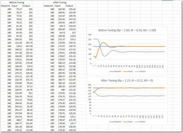
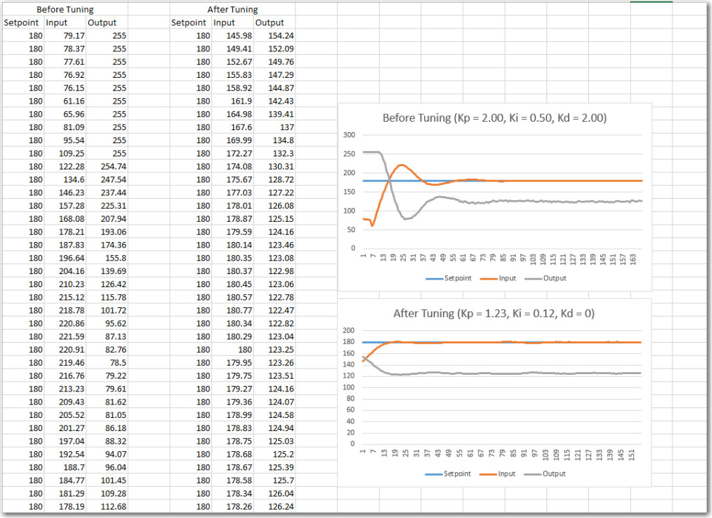
Anyway, after reading through a lot of the introductory material and even understanding some of it, I decided to give the PID Autotune library and the associated example sketch a try.  I downloaded the library, and fired up the example sketch using a spare Arduino Uno I had laying around.  After the requisite amount of fumbling around, I started getting some recognizable output on the serial monitor, and after a while I even figured out how to enable the auto-tuning feature.  The following printout and associated Excel plots show the results before and after tweaking the PID tuning constants.

PID Autotune library example.  Data and Excel plot of before and after auto-tuning, with simulated input/output.

PID Autotune library example. Data and Excel plot of before and after auto-tuning, with simulated input/output.

From the plots it is pretty obvious that the auto-tuned PID parameters do a much better job of acquiring and tracking the setpoint.

This is pretty awesome stuff, and I definitely plan to try a PID controller for Wall-E my wall-following robot.  However, here in the real world there are a few flies in the PID ointment, especially with respect to auto-tuning.  Most significantly, the auto-tuning process takes about 9 cycles of input/output swings to come up with suggested tuning constants, and acquiring those 9 cycles without Wall-E wandering off into the middle of the living room or crashing into a wall (or even worse, being snagged by the dreaded ‘stealth slippers from hell’ (aka the wife’s fuzzy slippers).   I may just have to suck it up on this one and tune the PID constants manually, we’ll see.

Stay tuned!

Frank