
Posted 12/05/16
I’ve been making some progress with the planned charging station lead-in rails. These rails (shown in yellow in the image below) are intended to guide the robot into the charging station, lining it up properly with the charging station so the contacts on the bottom of the robot will properly mate with the corresponding contacts on the top of the charging station platform.
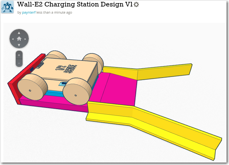
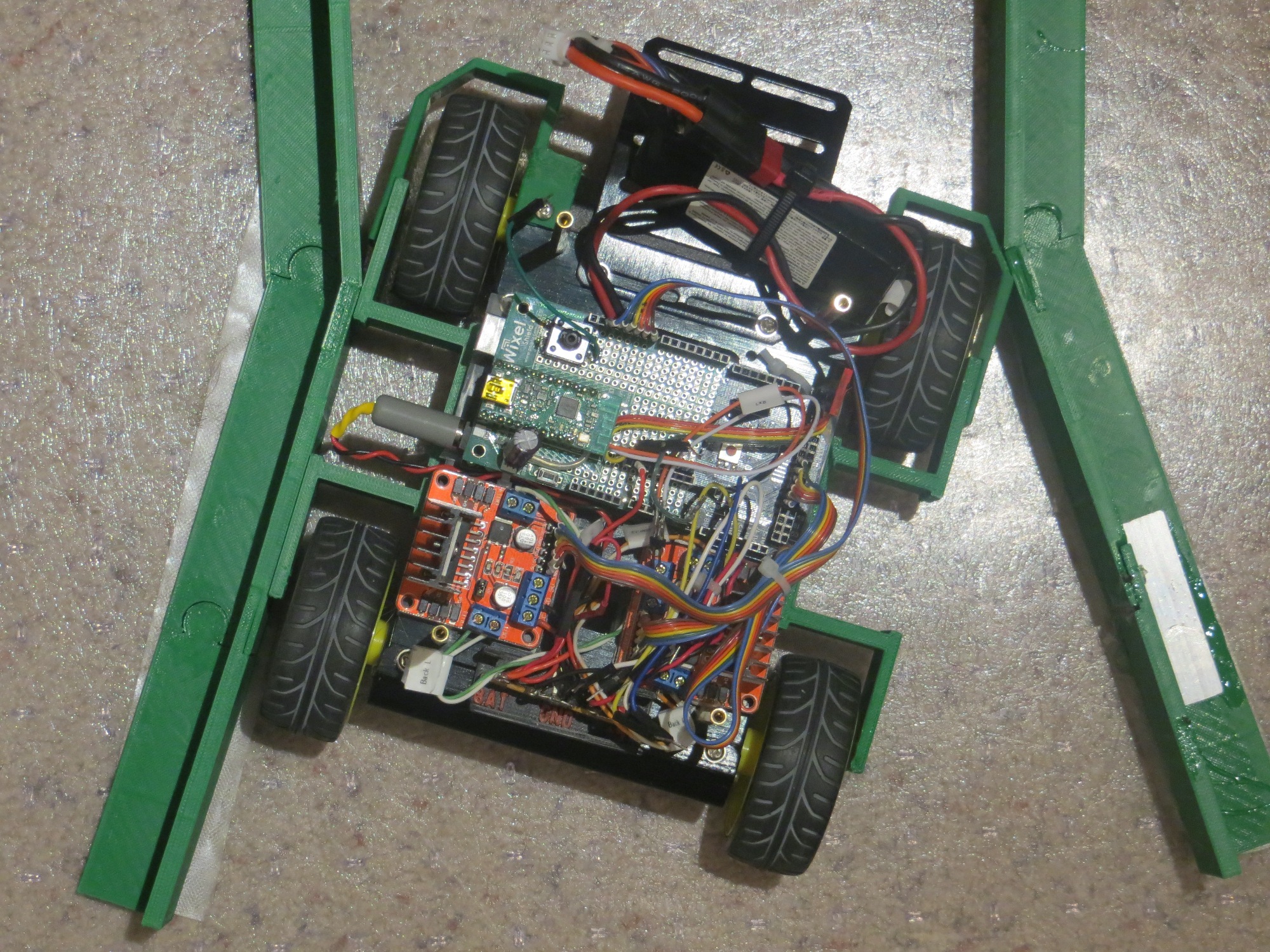
1/2-scale robot chassis on the 1/2-scale charging station model
These rails are too big to print in one piece on my PowerSpec PRO 3D printer, so I had to devise a way to print them in sections, which could then be plugged together to form the complete rail. To do this, I designed a coupling geometry consisting of a ‘puzzle-piece’ connector and a slide-fit arrangement, as shown below:
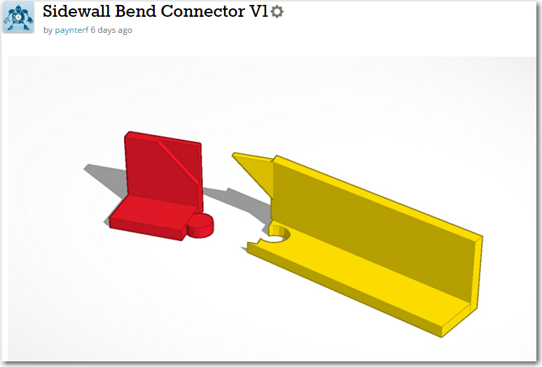
Lead-in rail angle coupling design
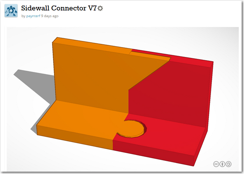
Lead-in rail straight coupling design
After going through several iterations ‘on paper’, I printed out a 1/2 scale model to verify that I could indeed connect the pieces to make a whole lead-in rail, as shown below:
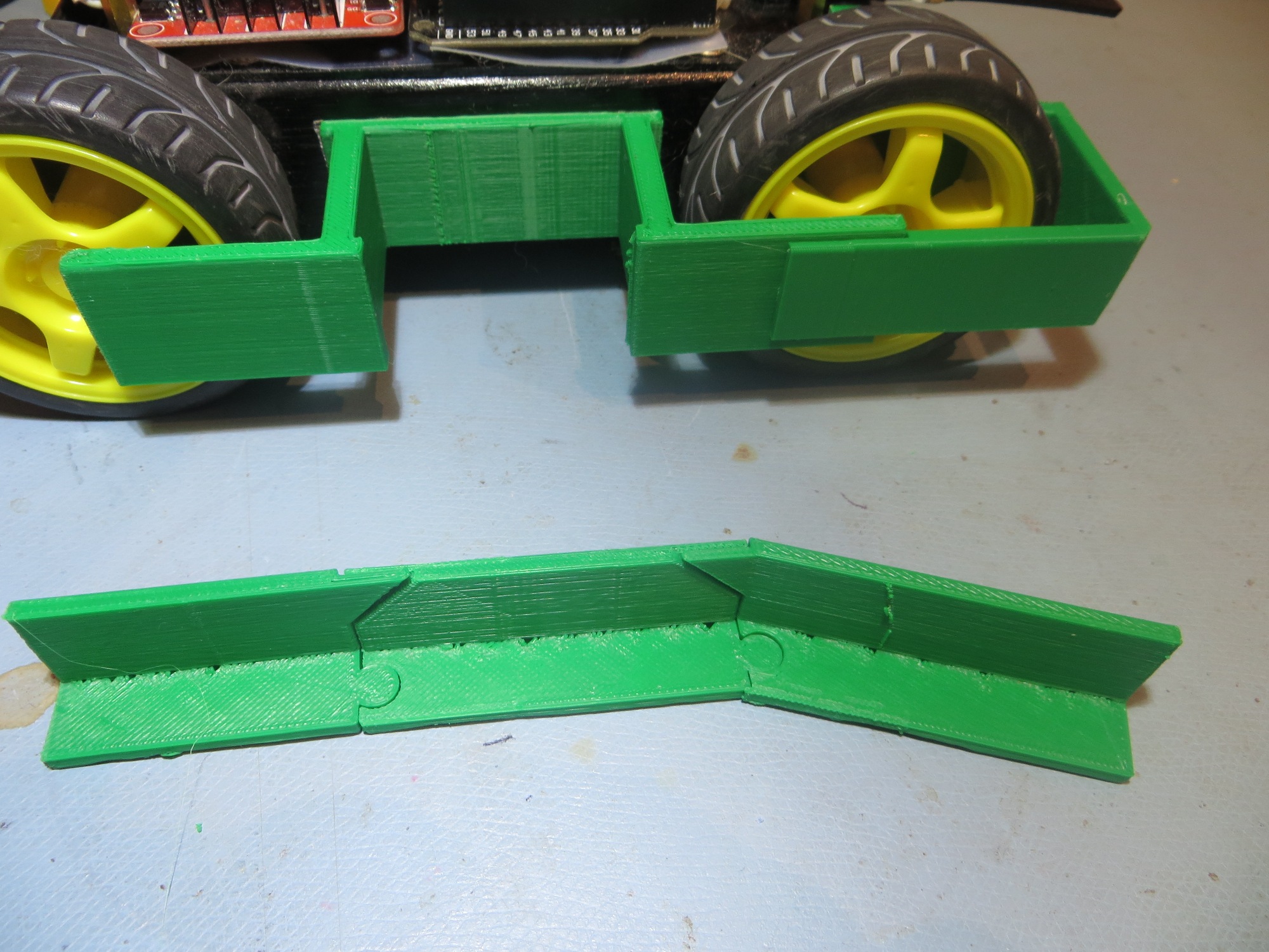
Half-size capture basket rail
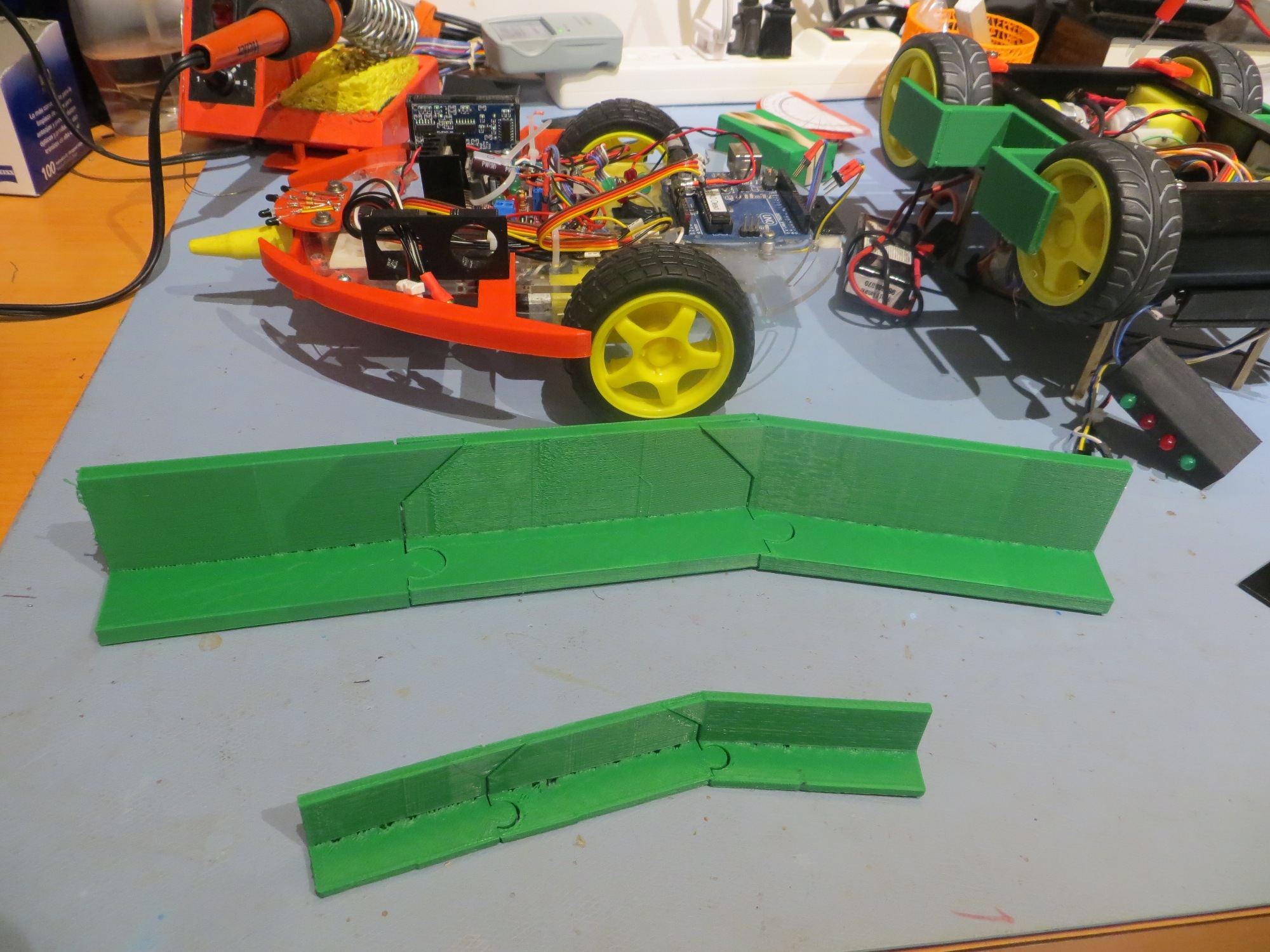
Half- and Full-size capture basket rails
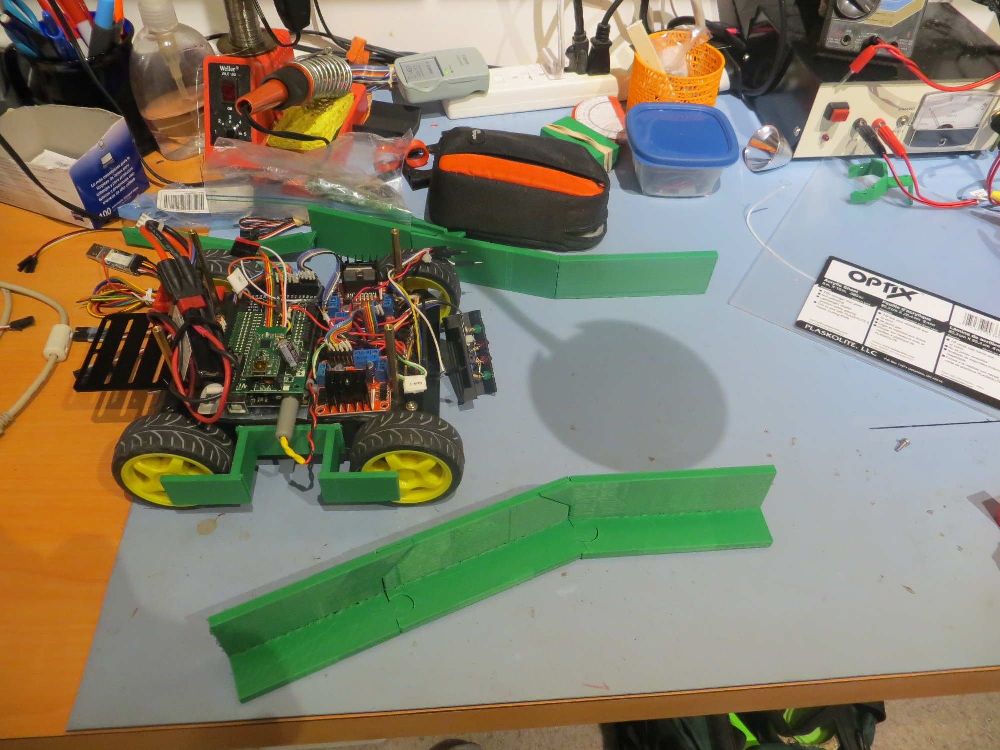
Full-size capture basket rails
Now that I had the capture rails fabricated, it was time to find out whether or not the capture system would actually work. I used double-sided tape to affix the two rails to one section of the heavy plastic desk-chair runner system in my lab/office, at the proper spacing to just pass the robot, assuming it was properly aligned with the capture gap, and then ran some tests, as shown in the attached video clip.
In the video clip, the first two trials were conducted with the ‘stock’ wheel guards with right-angle corners, and the remaining ones were conducted after filing a small bevel into the front corners to (hopefully) alleviate the sticking problem
Front wheel guard with filed bevel on outboard corner
After seeing that the filed bevel seemed to improve performance, I decided I would go ahead and redo the wheel guards to provide a more pronounced bevel. Thanks to TinkerCad and my trusty 3D printer, this was a piece of cake.
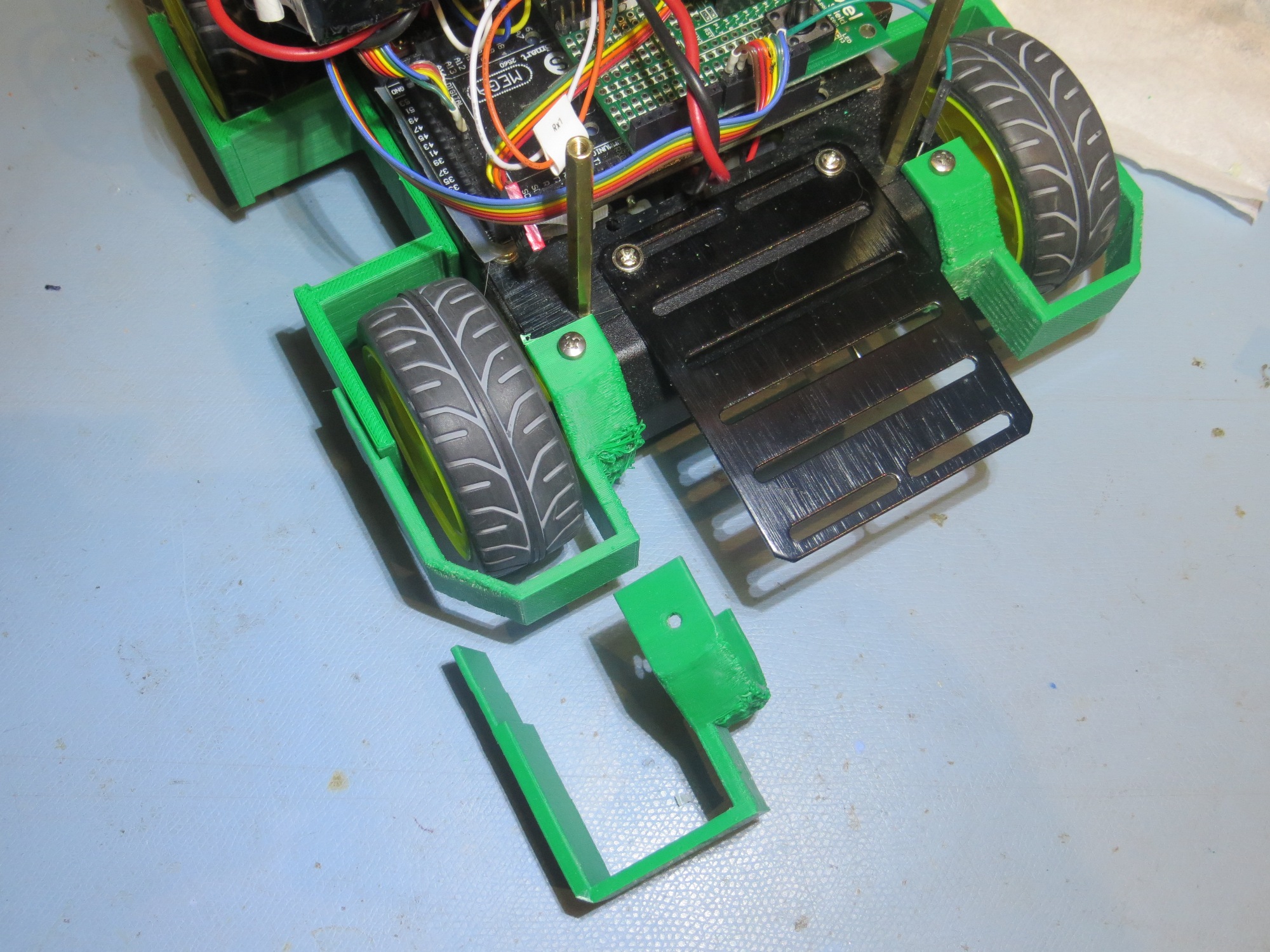
Redesigned wheelguard to incorporate bevel on outboard corner
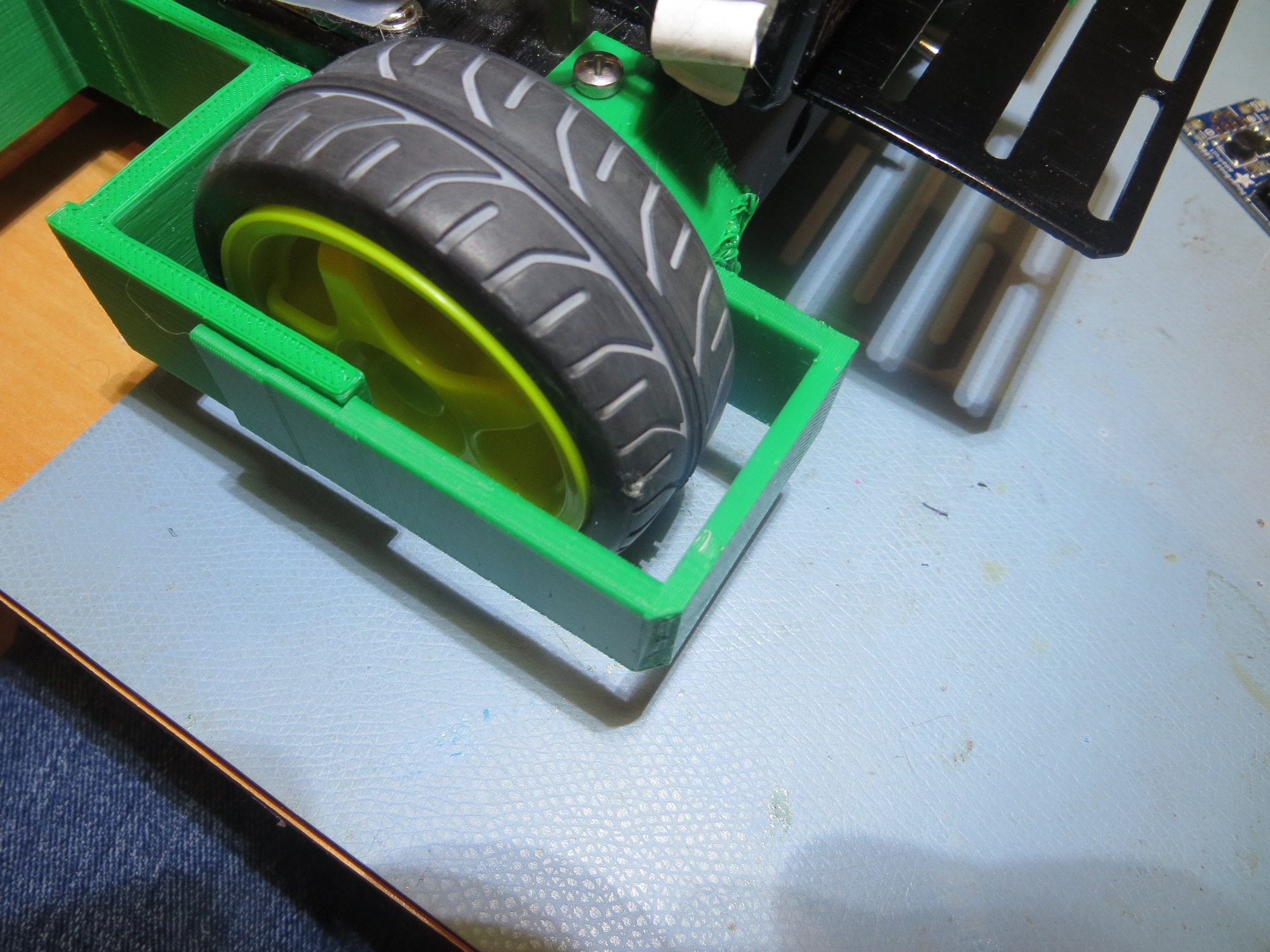
After changing out the wheel guards, I ran some more tests with my taped-down capture basket, but soon discovered yet another ‘capture failure mode’, as shown in the following image.
Robot stuck in capture basket
As you can see in the image, the rear part of the front wheel guard and the front part of the opposite wheel guard is just the right shape and spacing to form a stable lockup configuration. To address this little problem, I decided to remove the rear portion of the front wheel guard on each side, but left the two rear wheel guards intact. Then I ran some more capture basket tests, with very encouraging results.
So, at this point I’m pretty happy with the capture basket lead-in rail design (3 failures in 14 tries), and with the robot wheel guards. Next, I’ll need to fabricate a full-scale charging platform for the robot to stop on, and also work on the new charging/battery setup in the robot itself. Stay tuned!
Frank