Posted 19 May 2019
Over the last few weeks I have noticed that Wall-E2, my wall-following robot, seems to be suffering from a general lack of energy. I’ve been doing some testing involving a series of 45 degree S-turns, and Wall-E2 is having trouble moving at all, and when it does move, it does so very slowly. At first I thought this might be due to a low battery condition, but it exhibits the same behavior even with a fully charged battery pack. Then I thought it might be the battery pack itself dying, but now that I can monitor Wall-E2’s operating current and voltage ‘on the fly’ it is apparent that the battery pack is healthy and delivering rated power – it’s just that the power doesn’t seem to be getting to the motors. About this same time I began noticing that the cheap L298N motor drivers I have been using were getting pretty hot; enough to burn my finger, and enough to cause a ‘burning insulation’ smell.
So, I decided to go back to the drawing board and see what else is out there in terms of ‘better’ (whatever that means) motor and motor driver technology. As usual I started with a broad internet search and then started narrowing down to specific technologies and modules as I learned more. What I learned right away is that the L298n technology is notoriously inefficient, as it uses a bipolar transistor H-bridge which pretty much guarantees 1-2V voltage drop between the motor power supply and the motors themselves. This technology has been superceded by MOSFET-based H-bridge modules with much lower voltage drops and commensurately higher efficiencies. In fact, most of the modules I found no longer require heat sinks due to the much lower power dissipation.
VNH5019 Motor Driver Carrier
The Pololu VNH5019 Motor Driver Carrier is a single-channel motor driver based on the STMicroelectronics VNH5019 chip, with the following major features:
- Relatively high cost compared to other products – about $25 ea.
- 5.5 – 24V operating range. This matches well with Wall-E2’s battery output range of 7-8.4V.
- Very low Rds(ON) – less than 100mΩ. This means almost no voltage drop at the typical motor operating current of 100-200mA, and only about 0.2V at 2A stall current, or 0.4W power dissipation, worst case.
- Peak operating current of 12A – way more than I’ll need.
- There is also a current sensing output, but it’s only accurate during the active drive portion of the PWM waveform. Although I could probably deal with this by timing measurements to coincide with the drive cycle, I probably won’t bother, as I already have independent current measurement capability.
- Very simple operation – essentially identical to the L298n scheme.
There are, however, two major drawbacks to this option; the first is that the modules are single-channel only, so I either need to use four (one for each motor) or run two motors in parallel. The second is that they are much more expensive (like an order of magnitude) than the L298n driver modules.
TB67H420FTG Dual/Single Motor Driver Carrier
Pololu’s TB67H420FTG Dual/Single Motor Driver Carrier uses the Toshiba TB67H420FTG part, with the following features:
- Single or dual channel operation. In dual motor mode, each channel is limited to 1.7A, which should be OK for Wall-E2’s motors.
- Minimum motor drive voltage is specified as 10V. This is too high for my 2-cell LiPo setup that tops out at 8.4V. It’s still possible it will work OK down to 7V, but only experimentation will tell
Well, this is a much cheaper part ($10 vs $25) and each part can potentially handle twice the number of motors. Nominally $20 for four motors vs $100. However, the minimum motor voltage of 10V is probably a deal breaker. Besides, if I parallel two motors on each VNH5019 module, the price differential drops to 2.5:1 vs 5:1 and I don’t have to worry about the minimum motor supply voltage.
TB9051FTG Single Brushed DC Motor Driver Carrier
The Pololu TB9051FTG brushed DC motor driver is based on Toshiba’s TB9051FTG part, and has the following features:
- Low price – $8.49 (single channel)
- Compatible motor supply voltage range (4.5 – 28V).
- Can deliver 2.6A continuously, which should be much more than I’ll ever need
- 1″ x 1″ form factor, so fitting four modules onto Wall-E2’s chassis shouldn’t be too much of a problem
According to the TB9051FTG’s datasheet, the Rds(ON) has a max of 0.45Ω, so very little IR drop & power loss. This could make a very nice setup, even if I have to use four modules. This will still cost much more than my current dual L298n setup, but well worth it for the much lower voltage drop.
Dual TB9051FTG Motor Driver Shield for Arduino
This board is a dual-channel version of the above single-channel part, sized and laid out as an Arduino compatible ‘shield’ module. Pertinent features:
- $19.95 ea – essentially the same per-channel price as the single channel version
- Same voltage (4.5 – 28V) & current (2.6A continuous) range per channel
- Motor driver control pins broken out on one side so can be used without an Arduino
- Size is 1.9″ x 2.02″ or about 4 times the area of the single-channel boards. This is undoubtedly due to the requirement to physically match the Arduino Uno/Mega pin layout.
This isn’t really a good option for my Wall-E2 project, as I can fit four of the single channel modules in the same footprint as one of these boards – effectively making a 4-channel version in the same footprint.
Dual MAX14870 Motor Driver for Raspberry Pi (Partial Kit)
This module uses the Maxim MAX14870 part on a board physically compatible with the later versions of the Raspberry Pi microcomputer. Pertinent parameters
- Reasonable cost – $12.75 means the per-channel cost is around $6.50/channel.
- Small size: 0.8″ x 1.7″, so all four channels would fit in a 1.6″ x 1.7″ space. This is significantly smaller than the 2 x 2″ space requirement for 4 ea TB9051FTG modules
- Same 4.5 – 28V motor supply range, and same 1.7A continuous/channel current rating.
- Low Rds(ON) – less than 0.3Ω
This unit looks very promising; it’s small size and form factor, combined with dual motor control could make it the winner in the ‘replace the L298n’ project.
Adafruit DRV8833 DC/Stepper Motor Driver Board
This is a dual H-bridge for higher current applications than the non-current-limiting Featherwing can handle. It can handle one stepper or two DC brushed motors and can provide about 1.2A per motor, and expects a motor drive input of 2.7-10.8VDC. From the documentation:
- Low MOSFET ON resistance (approx 360 mΩ)
- 1.5A RMS output current, 2A peak per bridge
- Power supply range 2.7 – 10.8 V
- PWM winding current regulation and Current Limiting
- Overcurrent protection, short-circuit protection, undervoltage lockout, overtemp protection
- Reasonable per-channel cost; $5 per module, but each module will handle two motors – nice!
Adafruit DRV8871 Single Channel Motor Driver:
This is a single H-bridge for even higher current applications. From the documentation:
- 6.5V to 45V motor power voltage
- Up to 5.5V logic level on IN pins
- 565mΩ Typical RDS(on) (high + low)
- 3.6A peak current
- PWM control
- Current limiting/regulation without an inline sense resistor
- Overcurrent protection, short-circuit protection, undervoltage lockout, overtemp protection
- Higher per-channel cost; $8 per module, so $32 for all 4 motors
I was thinking that I might be able to use just two of these modules and parallel the left motors on one and the right motors on the other; this would give me 4 motor drives for $16, so comparable to the DRV8833. However, even if I use one per channel, the 4 units would still occupy a smaller footprint than the current setup with two L298N driver modules (and even less if I stack them vertically)
Adafruit Featherwing Motor Driver:
The Adafruit Featherwing motor driver kit is intended to plug into Adafruit’s ‘Feather’ microcontroller product, so to integrate it into my Mega 2560 project I’ll need to make sure I interface to the proper pins, etc. The module uses I2C for communications and motor control, so the low-level drivers for this module will be quite different than the ones currently in use for my Wall-E2 robot. Looking over the Adafruit documentation, I get the following:
- Motor Power and Motor outputs: these are all on 2-pin terminal blocks, so no changes
- Logic Power Pins: The Featherwing requires 3.3V & GND on the 2nd & 4th pins on the ‘long’ header side, counting from the end with three terminal blocks.
- I2C Data Pins: Last two pins on the ‘short’ header side
- I2C Addressing: The default feather address is 0x60, so it should be OK. The Wall-E2 project currently has four devices connected to the I2C bus;
- IR Homing Teensy uC slave at addr = 0x08
- FRAM module at addr = 0x50
- DS3231 RTC at addr = 0x68 (fixed)
- MPU6050 IMU module at addr = 0x69
- Smaller voltage range (4.5 – 13.5V), but OK for my 2-cell LiPo application with max V <= 8.5V
- Lower max current rating – 1.2A/channel; this could be a problem, but I don’t think so; the motors draw less than 0.5A, and won’t ever need 1.2A except in stalled rotor configuration, where it doesn’t matter. However, there is no current limiting on the Featherwing, so it is entirely possible to burn out a channel if the limit is exceeded!
- Reasonable cost on a per-channel basis. The board costs $20, but it will drive all four motors, for a per-motor cost of only $5 – nice!
So, I ordered several of each of the above parts, with the idea of running some simple tests of each and picking the one that best suits my application
Adafruit Featherwing Motor Driver Testing:
The first unit I tested was the Adafruit FeatherWing. I set up a spare Mega 2560 as the controller. This turned out to be quite simple, as there are only four connections; 3.3V, GND, SCL and SDA. I used my DC lab power supply to provide 8.0V, and used two spare JGA25-370 geared DC motors connected to M1 and M3 for the test. As the following short video shows, this worked great.
As a side-effect of this test, I noticed that one of the JGA25-370 210RPM gear motors seemed to be behaving a little differently than the other. After some experimentation, I discovered that one motor required a speed control input of almost half the full-speed value to even start turning, while the other one seemed to respond correctly to even low level speed drive values. Some more investigation revealed that the ‘problem’ motor was definitely stiffer than the ‘good’ one, and when the problem motor was being driven from my lab power supply, the power supply output current went up to almost 1A until the motor started moving and then dropped down to under 100mA while the motor was actually running. The ‘good’ motor current stayed under 100mA for the entire range of speeds.
I continued by connecting all four JGA25 gear motors and noticed that only one was really functioning properly, and the other three all had difficulty at low commanded speeds. To investigate further, I added an Adafruit INA219 high-side current sense module to the circuit so I could record both the current and power for each step on each channel. I ran all 4 motors in sequence, and then plotted the results in Excel as shown below
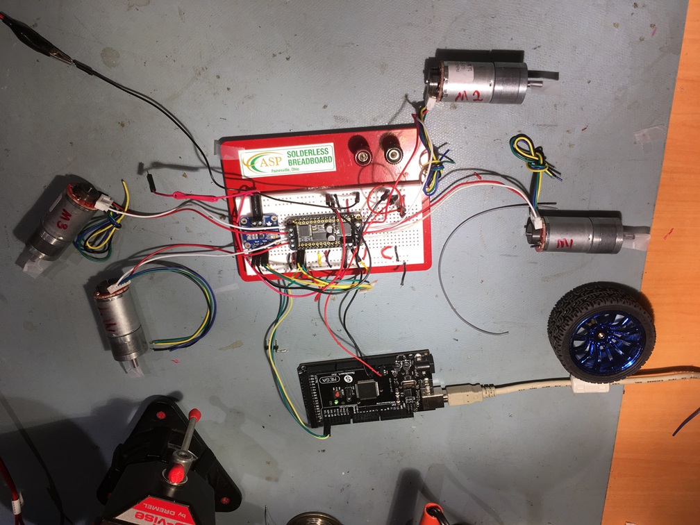
Testing all 4 JGA25-370 motors
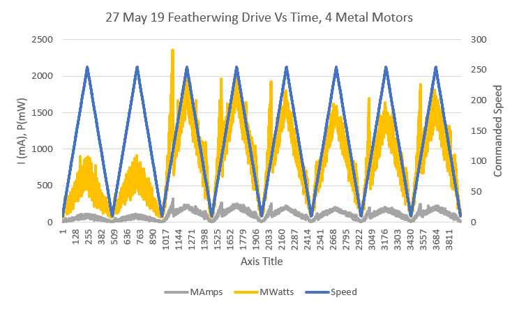
Current and Power vs time for 4 JGA25-370 motors. Note the current/power spikes when the ‘sticky’ motors turn ON
After some posts on the Adafruit forum, I was able to troubleshoot the motor problems to some extent. I was able to free up one of the troublesome motors by exercising the gear train, but on two other motors it became obvious that it was the motors themselves, not the gear train that was sticking. A 50% (or 75% depending on one’s threshold) failure rate isn’t very good. One of the posters on the Adafruit forum suggested I take a look at the metal gear motors offered by Pololu, and I ordered some of their ’20D’ motors for evaluation.
After testing the metal gear motors, I tried some of my stock of plastic motors, as shown in the following photo and Excel plot.
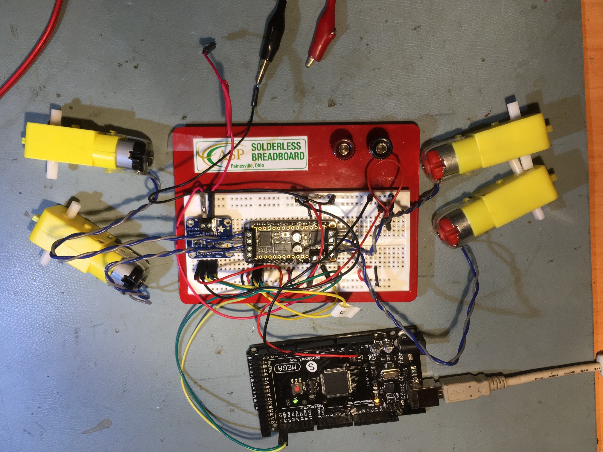
two ‘red cap’ and two ‘black cap’ motors
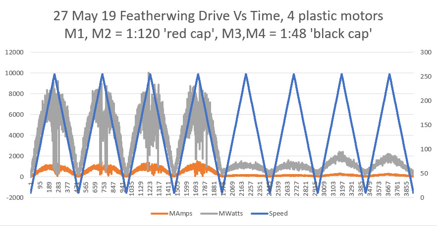
Current and Power vs time for two ‘red cap’ and two ‘black cap’ motors
All four motors behaved reasonably well, but as shown in the above plot, the ‘red cap’ motors drew a LOT more current than the ‘black cap’ ones. This was a mystery to me until I measured the coil resistance of the two types. The ‘red cap’ motors exhibited coil resistances of about 1Ω, whereas the ‘black cap’ motors were more like 5.7Ω. I surmise that the ‘red cap’ motors are for 3V applications and the ‘black cap’ ones are for 6-12V.
After this, I decided to test the motors currently installed in my Wall-E2 robot, so I simply placed the prototype board containing the Featherwing and the Mega 2560 controller on top of the robot and rerouted the motor wires from the LN298 controllers to the Featherwing. The following photo and plot show the setup and the results.
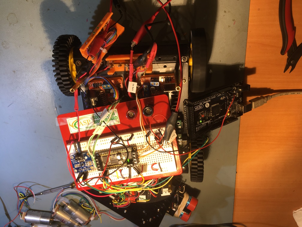
proto board on top of Wall-E2
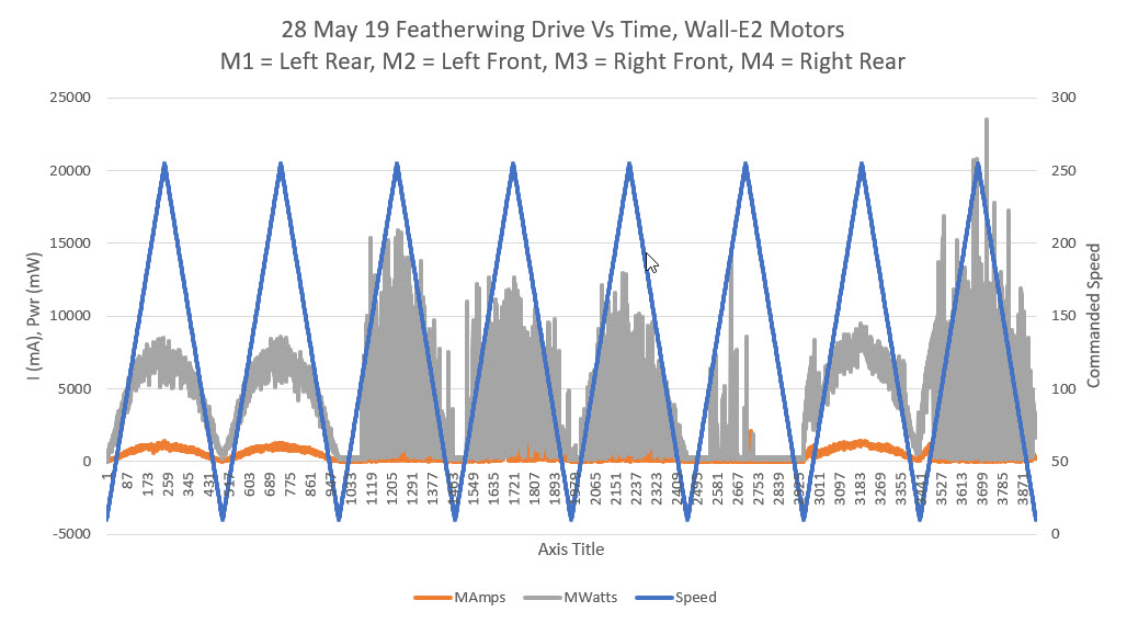
Current and Power vs time for the four ‘red cap’ motors currently installed in Wall-E2
Of the four installed ‘red cap’ motors currently installed in Wall-E2, only two (M1 & M4 above) exhibited reasonable performance – the other two were basically inoperative. Some closer inspection revealed that M3 exhibited essentially infinite coil resistance, i.e. an open circuit. Apparently I had managed to burn out this coil entirely, probably because the ‘red cap’ motors were intended for lower voltage applications.
Adafruit DRV8871 Single Channel Motor Driver Testing:
I removed the Featherwing module and replaced it with Adafruit’s DRV8871 Driver module. This module uses two PWM outputs to drive and direction control (vs I2C for the Featherwing) and is very simple to hook up and use. After getting it hooked up I ran a Pololu ’20D’ metal gear motor and a ‘good’ JGA25-370 over one complete up/down speed cycle, with no mechanical load. This produced the plots shown below:
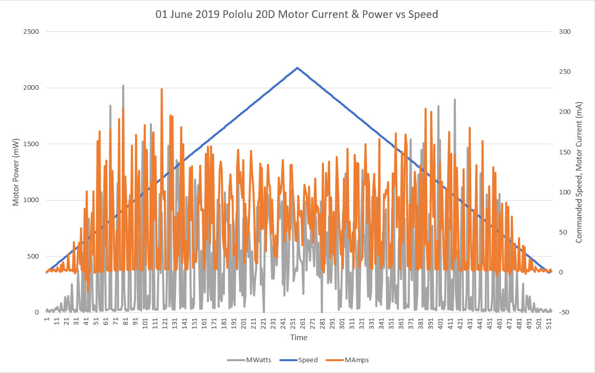
Pololu 20D metal gear motor with DRV8871 Motor Driver
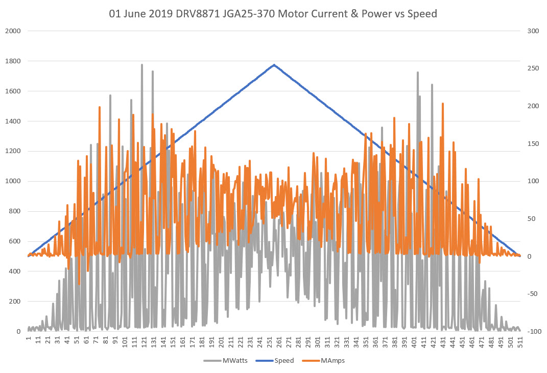
JGA25-370 metal gear motor with DRV8871 Motor Driver
Since I had already tested the same JGA25-370 motor with the Featherwing driver, I thought I would get similar results. However, the earlier Featherwing test produced a significantly different plot, as shown below
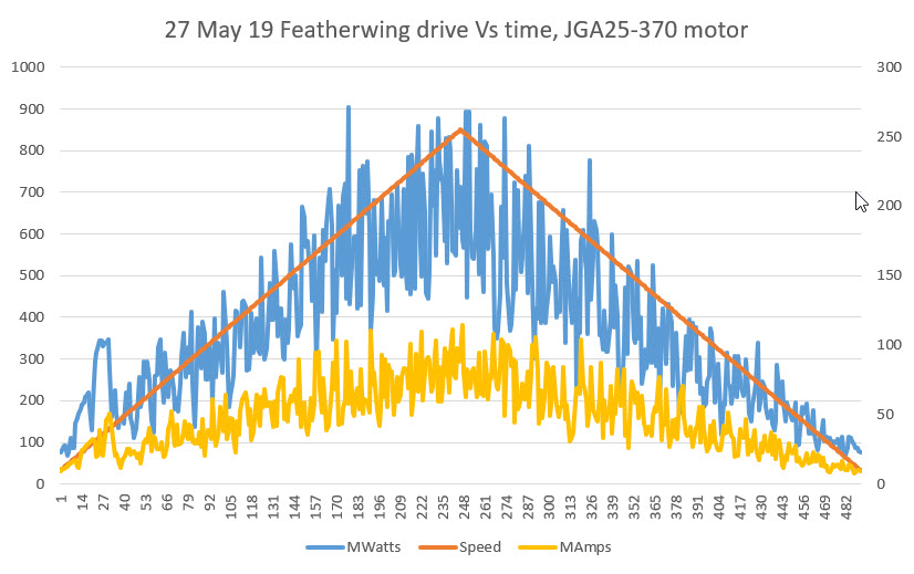
JGA25-370 metal gear motor with Featherwing driver
Why the differences? The coarseness of the DRV8871 plot versus Featherwing may well be because the DRV8871 uses the Arduino PWM outputs at the default frequency of around 980Hz, and I suspect the Featherwing PWM frequency is much higher. However, this doesn’t explain the dip in both power & current at the peak of the speed curve.
Frank
Pingback: Arduino Remote Programming Using A HC-05 Bluetooth Module - Paynter's Palace
Pingback: IMU Motor Noise Troubleshooting, Part III | Paynter's Palace
Pingback: Wall-E3 Replacing Mega 2560 With Teensy 3.5 | Paynter's Palace