Posted 10 June 2019
As part of my recent Wall-E2 Motor Controller Study, I reincarnated my old 2-motor robot as a test platform for Pololu’s ’20D’ metal gear motors. When I got the robot put together and started testing the motors, I realized I needed a way to remotely program the Arduino controller and remotely receive telemetry, just as I currently do with my 4-wheel Wall-E2 robot.
On my Wall-E2 robot, remote programming/telemetry is accomplished using the very nice Pololu Wixel Shield. However, I have been playing around with the cheap and small HC-05 Bluetooth module, and decided to see if there was maybe a way to use this module as a replacement for the Wixel.
As I usually do, I started with LOTS of web research. I found some posts claiming to have succeeded in remotely programming an Arduino using a HC-05 module, but the information was sketchy and incomplete, so I decided I would try and pull all the various sources together into a (hopefully) more complete tutorial for folks like me who want to use a HC-05 module for this purpose.
Overall Approach:
In order to remotely program an Arduino using a HC-05, the following basic parts are required:
- A wireless link (obviously) between the PC and the HC-05.
- A serial link between the PC and the Arduino and between the Arduino and the HC-05. This part is also well established, and the Arduino-to-HC-05 link can be done with either a hardware port (as with the Mega 2560) or a SoftwareSerial port using the SoftwareSerial library. My tutorial uses the Mega 2560, so I use Tx/Rx1 (pins 18/19) for the Arduino-to-HC-05 link
- A way of resetting the Arduino to put it back into programming mode, so the new firmware can be uploaded.
- A serial connection between the HC-05 and Tx/Rx0 on the microcontroller – more about this later.
The Wireless Link
The HC-05 is a generic Bluetooth device, and as such is compatible with just about everybody’s Bluetooth setup – phones and PC’s. I plan to use this with my Dell XPS15 9570 laptop, and I can pair with the HC-05 no problem. Here’s a link to a tutorial on pairing with the HC-05, and here’s another. As another poster mentioned, the pairing mechanism creates multiple ‘outgoing’ and ‘incoming’ COM ports, and it’s hard for me to figure out which to use. In this last iteration, I found that I could remove the two ‘incoming’ COM ports and use just the ‘outgoing’ one. Don’t know if that is the right thing, but….
A serial link between the PC, the Arduino and the HC-05
This part is discussed and demoed in many tutorials, but the piece that is almost always missing is why you need to have this link in the first place. The reason is that several AT commands must be used in order to configure the HC-05 correctly for wireless Arduino program upload, and (as I understand it anyway), AT commands can only be communicated to the HC-05 via it’s hardware serial lines, and only when the HC-05 is in ‘Command’ or ‘AT’ mode. The configuration step is a one-time deal; once the HC-05 is configured, it does not need to be done again unless the application requirements change.
A way of resetting the Arduino to accept firmware uploads
This is the tricky part. As ‘gabinix’ said in this post:
Hi Paul… To be honest I couldn’t find any tutorials to explain how to program/upload sketches with the HC-05. In fact, the conclusion you came up with is in-line with all the information out there. But it’s actually an extremely simple solution.
The only thing that keeps the HC-05 from uploading a program to arduino is that it doesn’t have a DTR (Data Terminal Ready) pin which tells the arduino to reset and accept a new sketch.
The solution is to re-purpose the “state” pin (PI09) on the breakout board. It’s purpose is to attach to an LED and indicate the connection status. It’s default setting is to send the pin HIGH when a connection is made, but you can simply enter into command mode of the HC-05 and use an AT COMMAND to tell it to send the pin LOW when a connection is made.
Voila! In about 1 minute of time you have successfully re-purposed the LED pin to a DTR pin which will reset your arduino to accept a new sketch when you hit the upload button.
A couple things to note… This will work for a pro-mini without additional hardware by connecting to the DTR pin. If you’re using an UNO or similar, you will need a capacitor in between our custom “state” pin and the reset pin on the uno. The reason is that the HC-05 will drive our custom pin LOW for the entire connection which would essentially be the same as holding the reset button the entire time. Having the cap in between solves that problem.
It a quick easy fix, takes about a minute to do. It’s just a lot harder to explain the steps to do it in a couple sentences.
Here’s a link to the AT COMMAND set —> http://robopoly.epfl.ch/files/content/sites/robopoly/files/Tutoriels/bluetooth/hc-05-at_command_set.pdf
and here’s a link to a tutorial, video, and sketch on how to enter the AT COMMANDS. —>
http://www.techbitar.com/modify-the-hc-05-bluetooth-module-defaults-using-at-commands.html<<< no longer available 🙁
So, the trick is to re-purpose the STATE output (PI09, AKA Pin 32, AKA LED2, see this link) via the AT+POLAR(X,0) command to go LOW when the connection to upload the program is first started. This signal is then connected to the Arduino’s RESET pin via the capacitor noted above (to make this signal momentary). The ‘Instructables’ tutorial on this subject at this link actually gets most of this right, except it doesn’t explain why the AT commands are being entered or what they do – so I found it a bit mysterious. In addition, it recommends soldering a wire directly to pin 32 rather than re-purposing the STATE output pin (re-purposing the STATE pin allows a no-solder setup). Eventually I ran across this link which contains a very good explanation of the AT commands used by the HC-05. The required AT commands are:
AT+ORGL  // resets the HC-05 to its original default state. AT mode must be re-established after this command

AT+ROLE=0 // sets it to 'slave' mode (prob not necessary as this is the default, but...

AT+POLAR=1,0 // sets the LED2/Pin32/STATE 'Connection' output to active LOW.

AT+UART=115200,0,0 // changes HC-05 'Data' (Bluetooth) Mode baud rate from the default 9600 to 115,200/0/0. Does not affect wired 'Command' (AT) Mode

AT+INIT // Initialize SPP Profile.
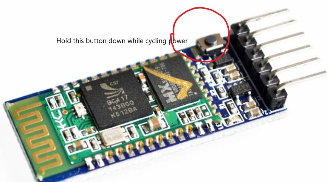
My module is the variety with a small pushbutton already installed on the ‘EN’ pin, so entering ‘Command’ mode is accomplished by holding the pushbutton depressed while cycling the power, and then releasing the button once power has been applied.
When this is done, the LED will change from fast-blink to a very slow (like 2 sec ON, 2 sec OFF) blink mode, as shown in the following short video:
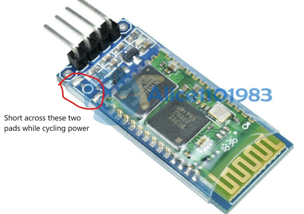
This indicates the HC-05 is in ‘Command’ mode and will accept AT commands. If you have the style without the pushbutton, you’ll have to figure out a way to short across the pads where the pushbutton should be, while cycling the power.
The screenshot below shows the result of executing these commands using the wired USB connection to the Arduino and the hard-wired serial connection between the Mega’s Tx1/Rx1 port and the HC-05 running in ‘Command’ mode.
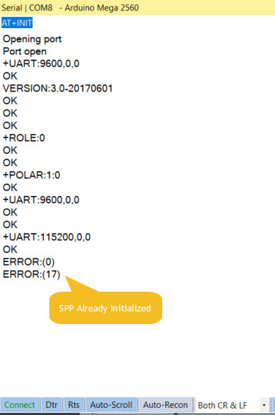
NOTE: The various posts and tutorials on the HC-05 describe separate AT ‘mini’ and ‘full’ command modes; the ‘mini’ mode only recognizes a small subset of all AT commands, while ‘full’ recognizes them all. ‘Mini’ mode is entered by momentarily applying VCC to pin 34, and ‘full’ mode is entered by holding pin 34 at VCC for the entire session. One poster described this as a flaw in the HC-05 version 2 firmware which might be corrected in later versions. It appears this may have been the case, as the HC-05 module I used responded with VERSION:3.0-20170601 and recognized all the commands I gave it (not a comprehensive test, but enough to make me think this problem has gone away).
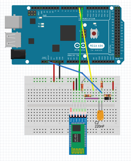
Wiring Layout for HC-05 Configuration via AT commands
I decided that this post was my chance to learn how to make ‘pictoral’ wiring diagrams using the Fritzing app. I had seen other posts with this kind of layout, and initially thought it was kinda childish. However, when I started working with Fritzing (in English, ‘Fritzing’ sounds like an adverb, not a proper noun – so a bit strange to my ears…), I realized it has a LOT of power, so now I’m a convert ;-).
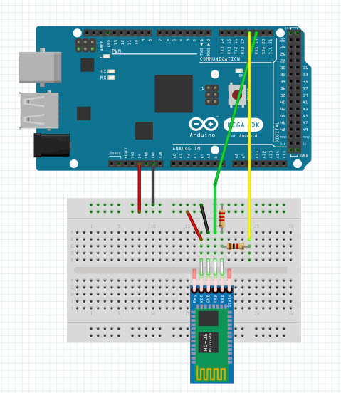
In the diagram above, I’m using the Rx1/Tx1 (pins 19/18) hardware serial port available on the Mega. If you are using a Uno, you’ll need to use SoftwareSerial to configure a second port for connection to the HC-05. A 2.2K/1.0K voltage divider is used to drop Arduino Tx output voltages to HC-05 Rx input levels, but no conversion is required in the other direction. The HC-05 can be powered directly from Arduino +5V, as the HC-05 has an onboard regulator.
Initial AT Configuration Arduino Sketch
void setup()
{
	Serial.begin(115200);
	Serial1.begin(38400);
}

void loop()
{
	if (Serial1.available())
	{
		Serial.write(Serial1.read());
	}
	if (Serial.available())
	{
		Serial1.write(Serial.read());
	}
}
All the code above does is transfer keystrokes from the Arduino to the HC-05, and vice versa. This is all that is required to configure the HC-05 using AT commands.
Serial Connection between the HC-05 and Tx/Rx0 for Program Uploads
Most Arduino microcontrollers are shipped with a small program called a ‘bootloader’ already installed. This small program is only active for a few seconds after a board reset occurs, and it’s job is to detect when a new program is being uploaded. If the bootloader sees activity on whatever serial port it is watching, it writes the incoming data into program memory and then transfers control to the user program. The stock Arduino bootloader only monitors Tx/Rx0 for this; activity on other ports (specifically Rx1 in my case) will be ignored and program uploads will fail. After the HC-05 has been initially configured via AT commands over the PC-to-Arduino-to-HC-05 serial links, the connection from the HC-05 to the Arduino must be changed so that PC-to-HC-05 data transferred over the Bluetooth link arrives at the Arduino’s Rx0 port so the stock bootloader will see it and write it to the Arduino’s program memory. This minor point wasn’t at all clear (at least not to me) in the various tutorials, so I wasted a LOT of time trying to figure out why I couldn’t get the last part of the puzzle to fit – ugh!
Shown below is my Fritzing diagram for the final configuration of my test setup, showing the Tx/Rx lines changed from Tx/Rx1 (pins 18/19) to Tx/Rx0 (pins 1/0). The HC-05 STATE output is connected to Arduino reset via a 0.22uF capacitor, with resistors to form a simple one-shot circuit. The STATE line goes LOW (after reconfiguration via the AT+POLAR=1,0 command) which causes a momentary LOW on the Arduino reset line. This is the magic required to upload programs to the Arduino wirelessly. When the Bluetooth connection is terminated, the STATE line goes HIGH again and the Arduino end of the now-charged capacitor jumps to well above 5V. The diode shown on the diagram clamps this signal to within a volt or so above +5V to avoid damage to the Arduino Reset line when this happens. This diode isn’t shown on any of the other tutorials I found, so it is possible the Arduino Reset line is clamped internally (good). It’s also possible it isn’t protected, in which case not having this diode will eventually kill the Arduino (bad).
Testing
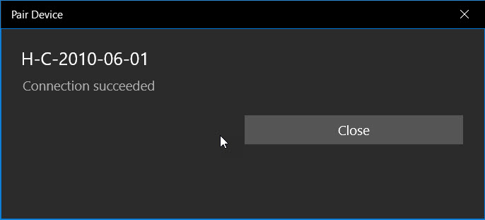
The first thing I did after configuring the HC-05 (using the above AT commands) was to see if I could still connect to and communicate with it over Bluetooth from my laptop. I used RealTerm, although any terminal program (including the Arduino IDE serial monitor) should do. The very first thing that happened is I had to re-pair the laptop with the HC-05, and the name given by the HC-05 was markedly different, as shown in the captured pairing dialog.
The next thing was to see if I could get characters from my BT serial connection through to my Arduino serial port. After fiddling around with the baud rates for a while, I realized that now I had to change the BT serial terminal baud rate from 9600 to 115200, and the Arduino-to-HC-05 baud rate from 38400 (the default ‘Command’ mode rate) to 115200. Once I did this, I could transmit characters back and forth between RealTerm (connected to the HC-05 via Bluetooth) and my Visual Studio/Visual Micro setup (connected to Arduino via the wired USB cable) – yay!
For the next step in the testing, I need to remove the hard-wired USB connection and power the Arduino from an external power source. When I did this by first removing the USB connector (thereby removing power from the HC-05) and then plugged in external power, I noticed that the HC-05 was no longer connected to my laptop (the HC-05 status LED was showing the ‘fast blink’ status, and my connection indicator LED was OFF). I checked in my BT settings panel, and the HC-05 (now announcing itself as ‘H-C-2010-06-01’) was still paired with my laptop, but just transmitting some characters from my RealTerm BT serial monitor did not re-establish the connection. However, when I changed the port number away from and then back to the BT COM port, this did re-establish the connection; the HC-05 status LED changed to the 2-blinks-pause-2-blinks cycle, and my connection LED illuminated.
So, now I connected the output of my STATUS line one-shot circuit to the Arduino reset line and changed my VS2017/VM programming port from the wired USB port to the BT port (interestingly it was still shown as ‘HC-05’ in Visual Studio/Visual Micro). After some initial problems, I got the ‘Connected’ status light, but the upload failed with the error message “avrdude: stk500v2_getsync(): timeout communicating with programmer” and the communication status changed back to ‘not connected’.
At this point I realized I was missing something critical, and yelled (more like ‘pleaded’) for help on the Arduino forum. On the forum I got a lot of detailed feedback from very knowledgeable users, most notably ‘dmjlambert’. Unfortunately dmjlambert was ultimately unsuccessful in solving the problem, but he was able to validate that the steps I had taken so far were correct as far as they went, and ‘it should just work’. To paraphrase the Edison approach to innovation, “we didn’t know what worked, but we eliminated most potential failure modes”. See this forum post for the details.
After this conversation (over several days), I decided to put the problem down for a few days and do other things, hoping that a fresh look at things with a clear head might provide some insight. A few days later when I came back to the project, I ran some tests suggested by dmjlambert to verify that the connection to the Arduino RESET pin via the 0.22uF capacitor did indeed reset the Arduino when the STATE line transitioned from HIGH to LOW. To do this I created a modified ‘Blink’ program that blinked 10 times rapidly and then transitioned to a steady slow blink. Using this program I could see that that the Arduino did indeed reset each time a Bluetooth connection to the HC-05 was established.
So, the problem had to be elsewhere, and about this time I realized I was assuming (aka ‘making an ass out of you and me’) that the program upload data being received over the Bluetooth link was somehow magically making it to the bootloader program. This had been nagging at me the whole time, but I ‘assumed’ (there’s that word again) that since this problem had never been mentioned in any of the tutorials or even in the responses to my forum posts, it must not be a problem – oops!
Anyway, to make a long story short, I moved the HC-05 – to – Arduino connection from Rx/Tx1 to Rx/Tx0 and program uploads started working immediately – YAY!!
I went back through the tutorials I had been following to see if I had missed this magic step, and didn’t find any references to moving the serial connection at all. So, if you are doing this with a UNO, you’ll need to move the serial connection from whatever pins you were using (via SoftwareSerial) to Rx/Tx0 as the last step. If you are using an Arduino Mega or other uino controller that supports additional hardware serial ports as I did, you’ll have to move the connection from Rx/Tx-whatever to Rx/Tx0 as the last step.
This tutorial was put together in the hope that I could maybe help others who are interested in using the HC-05 Bluetooth module for remote program uploads to a Arduino-compatible microcontroller, and maybe save them from some of the frustration I experienced. Please feel free to comment on this post, especially if you see something that I got wrong or missed.
13 Aug 2019 Update:
Here’s a short video showcasing the ability to program an Arduino Mega 2560 wirelessly from my Windows 10 PC using the HC-05 Bluetooth module
At the start of the video, the HC-05 status light is blinking rapidly, signalling the ‘No Connection’ state. Then, at about 2 seconds, the light changes to the slow double-blink ‘Connected’ state, the yellow LED on the Mega blinks OFF & then ON again, signalling that the Mega has been reset and is now awaiting program upload, followed immediately by rapid blinking as the new program is uploaded to the Mega’s program memory. During the upload, the HC-05 status LED continues to show the slow double-blink ‘Connected’ status. Then, at about 18 seconds, the program upload terminates and the HC-05 returns to the ‘No Connection’ state.
The small white part on the green perf-board is the 220 nF capacitor. The other two modules on the perf-board are a MPU6050 IMU and a high-side current sensor.
Stay tuned!
Frank
25 October 2021 Update:
I came back to this post to refresh my memory when trying to initialize and use a new HC-05 module for my new Wall-E3 project, and failing badly. I finally got something to work, but only after screwing around a lot. I realized I didn’t have a good handle on what mode the HC-05 was in – even though the onboard LED changes behavior to indicate the mode. So, here is a short video showing the LED behavior for the ‘disconnected’ and ‘connected’ modes.
In the above video, the HC-05 starts out in the normal power-on ‘disconnected’ state (rapidly flashing LED). Then after a few seconds a BT connection is established, and the LED behavior changes to ‘connected’ (two short blinks and a long pause). Then after a few more seconds the connection is dropped and the LED behavior changes back to ‘disconnected’ (rapidly flashing)