Posted 23 October, 2021
For some time now, I have been contemplating a replacement for the outdated and obsolete Mega 2560 micro-controller as the main controller module of my autonomous wall-following robot. The robot actually sports three controllers – the Mega 2560 main controller runs the overall operating system, drives the motors, and manages the speaker, the front-facing LIDAR unit, and a number of LEDs. A Teensy 3.2 manages the forward-facing IR-LED charging station beacon detection/homing algorithm, and a Teensy 3.5 manages the seven VL53L0X LIDAR distance measuring modules. So, it would make a lot of sense to replace the 2560 with another Teensy, making all the software consistent, and giving the robot a significant boost in computing power. A Teensy 3.5 at 120MHz runs at almost 10 times the 16MHz rate of the 2560, has twice the Flash memory (512K vs 256) and 32 times the RAM (256K vs 8). However, until recently (see this post) it has been very difficult/impossible to perform over-the-air (OTA) firmware updates with any of the Teensy products – a deal-breaker for me as I do that quite often with Wall-E2. Now that OTA capability has been demonstrated, the only remaining hurdle was whether or not a Teensy 3.5 has sufficient I/O to replace the Mega 2560. To address this question I created an Excel spreadsheet to document the current I/O assignments of the 2560 and then tentatively assigned Teensy 3.5 pins to match, as shown below.
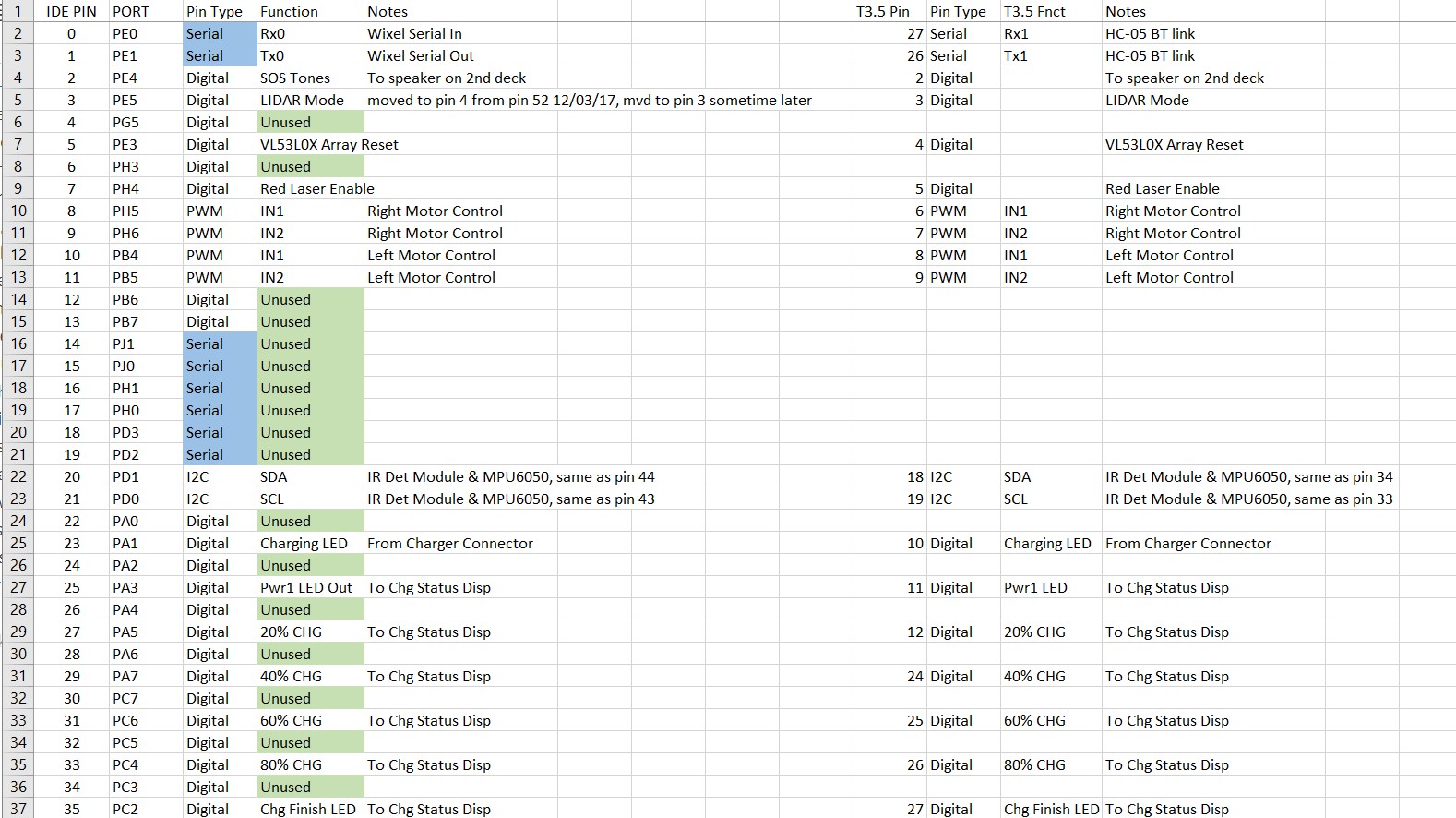
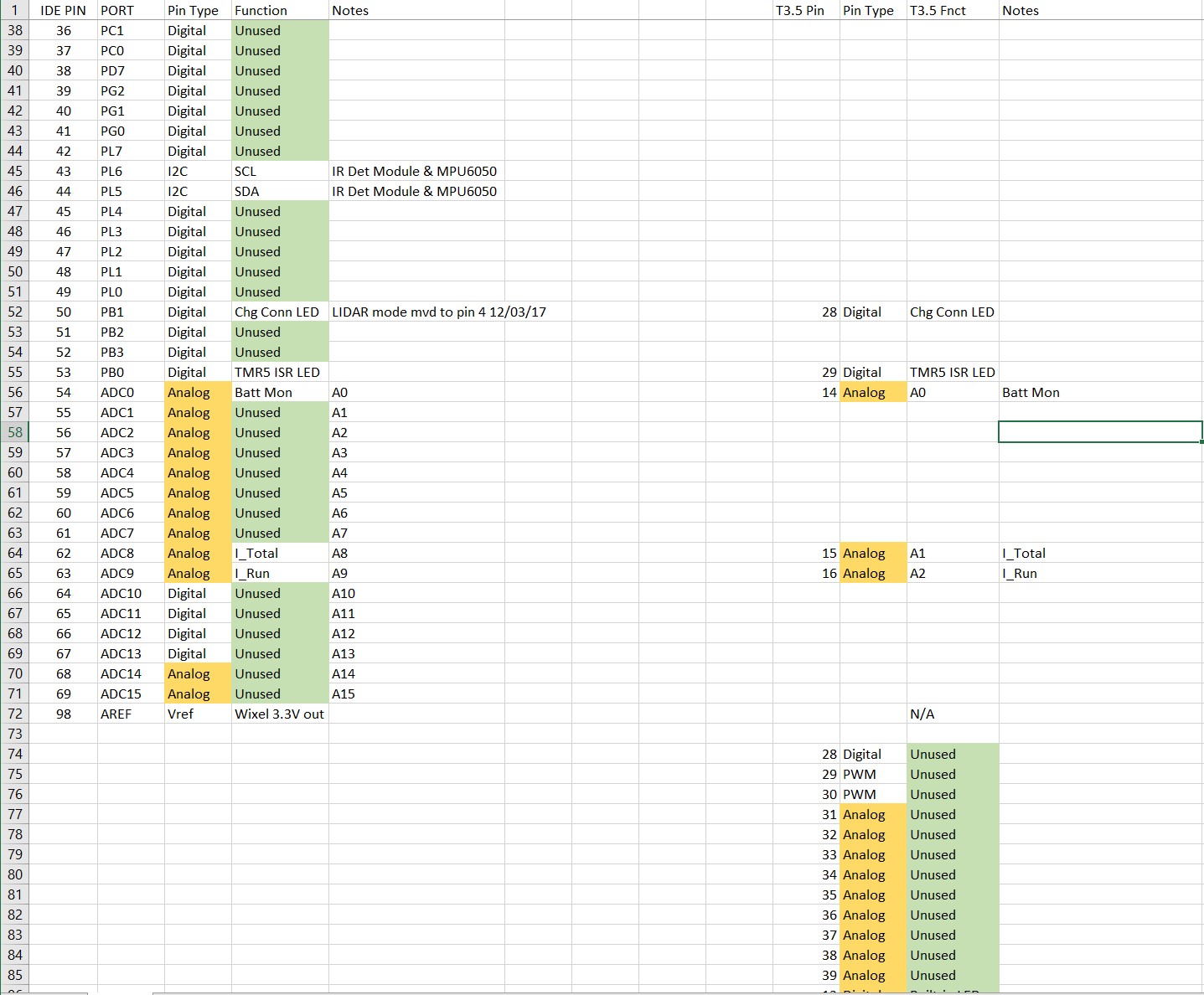
As can be seen from the above, the Teensy 3.5 has plenty of pins left over after all currently assigned Mega 2560 pin assignments have been covered, so that problem goes away too.
The last piece of the puzzle was just the inconvenience of changing out a currently-working Mega 2560 just to gain performance that may or may not really be necessary. However, now that I have decided to redo the entire chassis to address the turn side-slip problem (see this post), I plan to use the opportunity to start fresh with a Teensy 3.5 as the main controller and work out any problems with just the chassis, the motors and motor drivers and the Teensy before moving on to implementing the rest of Wall-E2’s capabilities.
Motor Drivers for Wall-E3:
I have a bunch of motor driver modules left over from an earlier motor driver study, so I decided to use two of the Pololu VNH5019 motor driver modules for Wall-E3 – one for the two left motors, and one for the two right motors.
01 November 2021 Update:
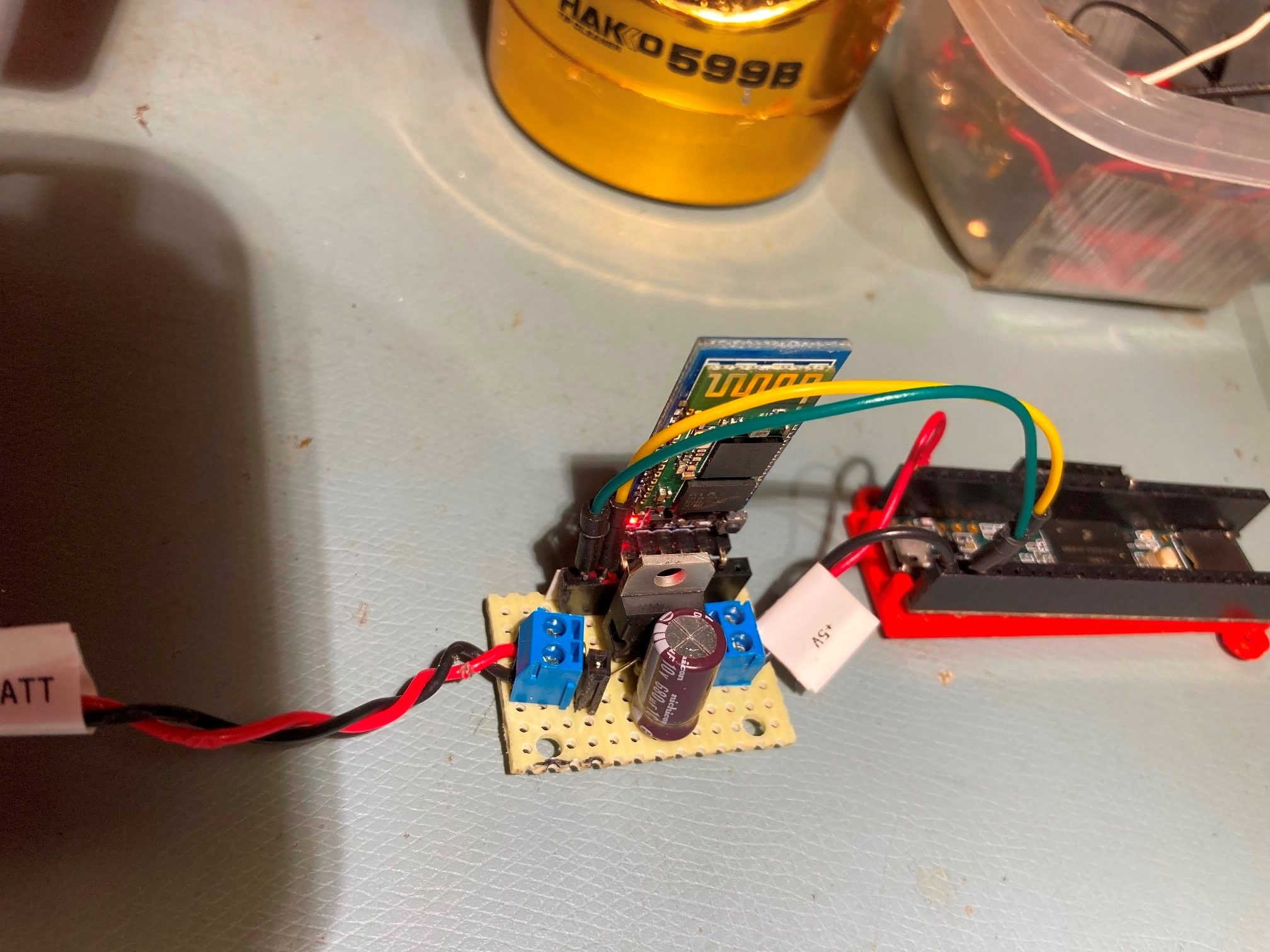
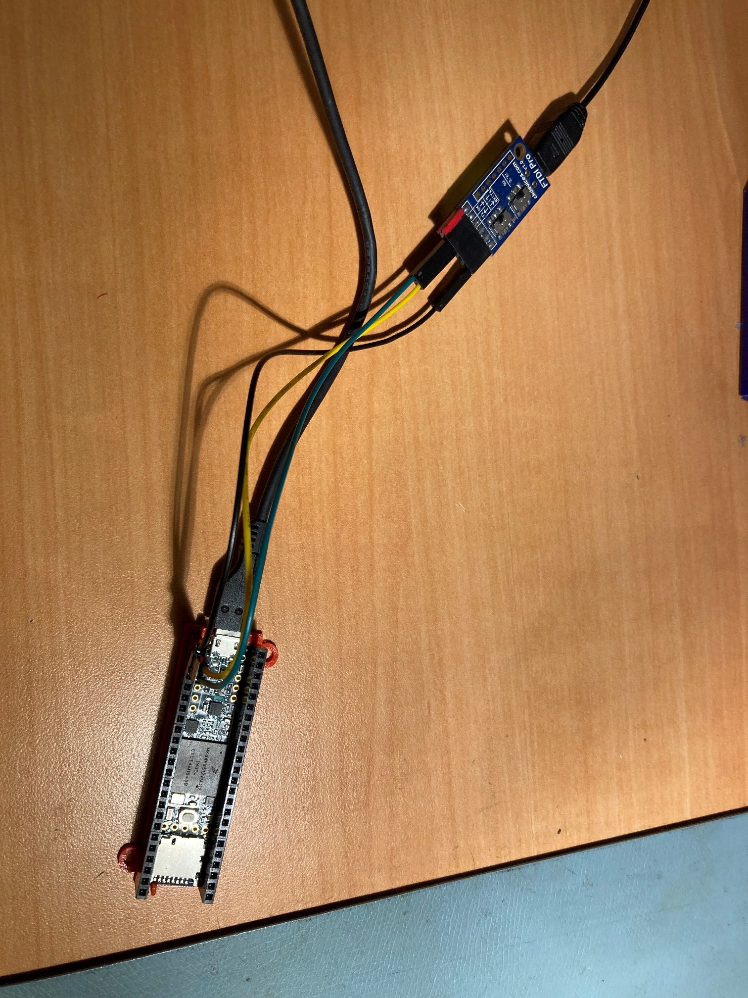
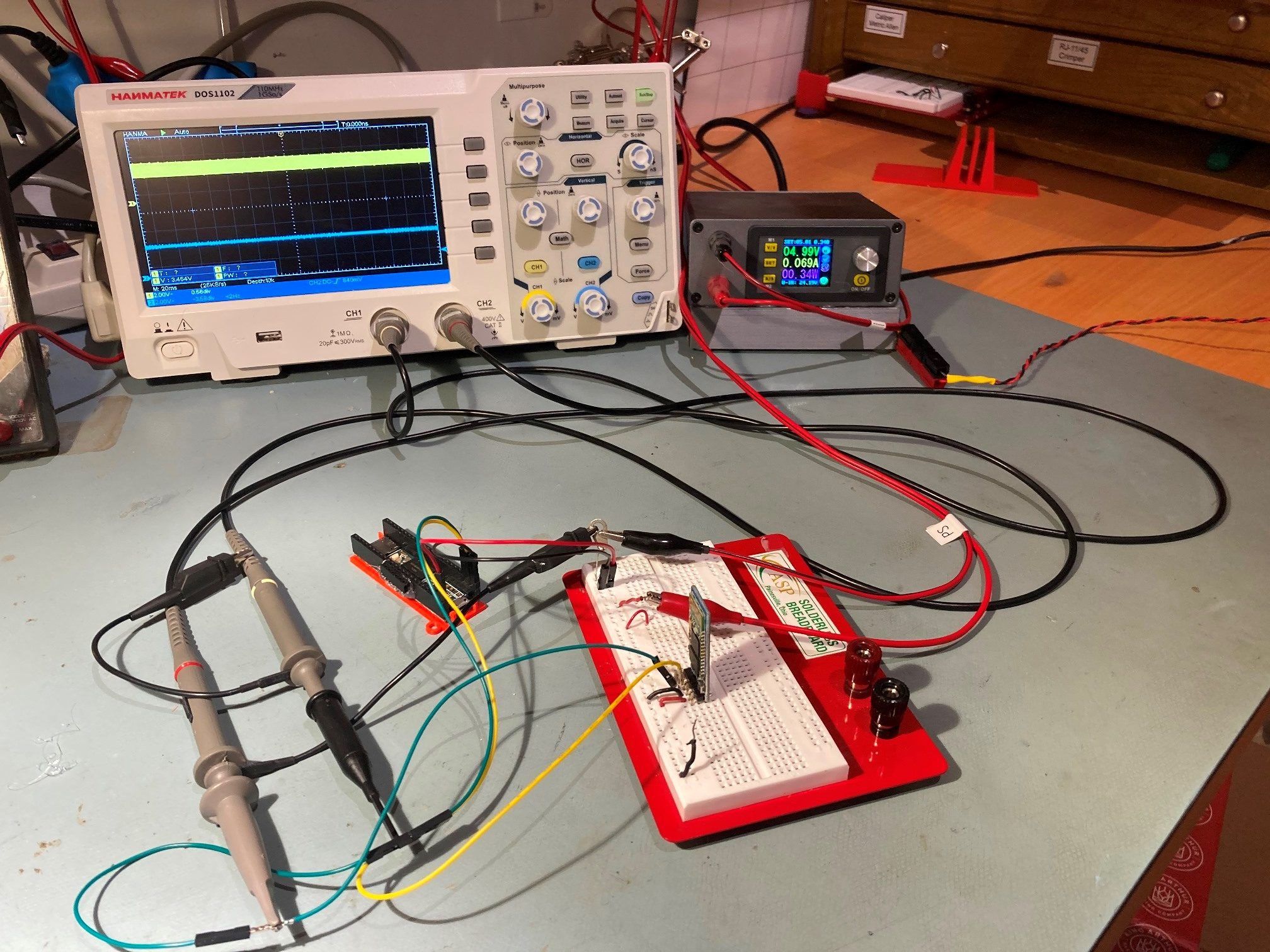
The first step in bringing up the Wall-E3 robot was to assemble a very basic system on a simulated chassis bottom plate, as shown in the following photo:
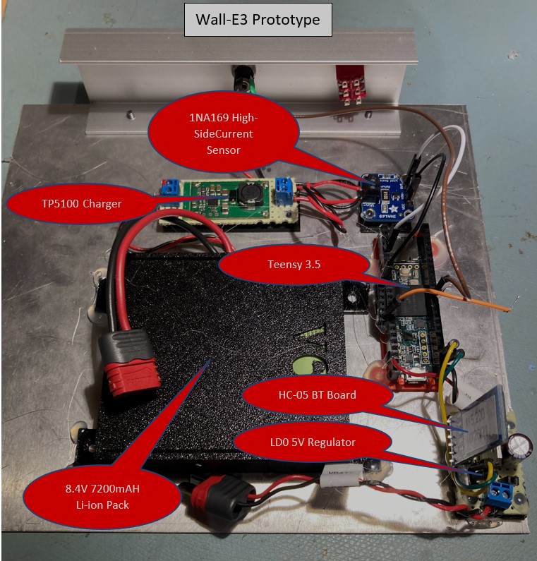
The basic system consists of a TP5100 charger system and a 8.4V 7200 mAH battery pack, an Adafruit 1NA169 high-side current sensor, a Teensy 3.5 and a auxiliary board containing a 5V LDO regulator and a HC-05 Bluetooth module. The Teensy’s program at this stage consists of the OTA update code developed earlier in this post and this post, plus a few lines to read the current sensor output, convert it to a current value, and send it to the BT serial port. Here’s the program:
|
1 2 3 4 5 6 7 8 9 10 11 12 13 14 15 16 17 18 19 20 21 22 23 24 25 26 27 28 29 30 31 32 33 34 35 36 37 38 39 40 41 42 43 44 45 46 47 48 49 50 51 52 53 54 55 56 57 58 59 60 61 62 63 64 65 66 67 68 69 70 71 72 73 74 75 76 77 78 79 80 81 82 83 84 85 86 87 88 89 90 91 92 93 94 95 96 97 98 99 100 101 102 103 104 105 106 107 108 109 110 111 112 113 114 115 116 117 118 119 120 121 122 123 124 125 126 127 128 129 130 131 132 133 134 135 136 137 138 139 140 141 142 143 144 145 146 147 148 149 150 151 152 153 154 155 156 157 158 159 160 161 162 163 164 165 166 167 168 169 170 171 172 173 174 175 176 177 178 179 180 181 182 183 184 185 186 187 188 189 190 191 192 193 194 195 196 197 198 199 200 201 202 203 204 205 206 207 208 209 210 211 212 213 214 215 216 217 218 219 220 221 222 223 224 225 226 227 228 229 230 231 232 233 234 235 236 237 238 239 240 241 242 243 244 245 246 247 248 249 250 251 252 253 254 255 256 257 258 259 260 261 262 263 264 265 266 267 268 269 270 271 272 273 274 275 276 277 278 279 280 281 282 283 284 285 286 287 288 289 290 291 292 293 294 295 296 297 298 299 300 301 302 303 304 305 306 307 308 309 310 311 312 313 314 315 316 317 318 319 320 321 322 323 324 325 326 327 328 329 330 331 332 333 334 335 336 337 338 339 340 341 342 343 344 345 346 347 348 349 350 351 352 353 354 355 356 357 358 359 360 361 362 363 364 365 366 367 368 369 370 371 372 373 374 375 376 377 378 379 380 381 382 383 384 385 386 387 388 389 390 391 392 393 394 395 396 397 398 399 400 401 402 403 404 405 406 407 408 409 410 411 412 413 414 415 416 |
/* Name: T35_WallE3_V1.ino Created: 10/25/2021 2:37:04 PM Author: FRANKNEWXPS15\Frank 10/30/21 - Added TeensyOTADemo code for basic OTA updates */ /* Name: TeensyOTADemo.ino Created: 10/9/2021 11:18:19 AM Author: FRANKNEWXPS15\Frank This program demonstrates the use of 'board.txt' post-build instructions in conjunction with a small C# command-line program for seamless 'over-the-air' (OTA) firmware update for Teensy modules. Implementation of OTA update requires that Joe Pasquariello's 'FlasherX' code be added to the Teensy sketch as it is below, and some code to allow an external serial communications program to trigger the update process. In the demo sketch below, the 'FlasherX' additions are the '#include FlasherTxx.h' line and the addition of the FlasherX specific code at the bottom. The trigger mechanism is provided by the 'CheckForUserInput();' call in loop. If the ASCII code for 'U' or 'u' is present on Serial1, the update process will be launched. */ #include "FlashTxx.h" // TLC/T3x/T4x flash primitives #include <elapsedMillis.h> elapsedMillis MsecSinceLastLEDToggle; //used for LED blink timer const double AREF = 3.3; //teensy default for analog inputs const double AmpsPerVolt = 1.00; //default 10K Rs const int MAX_AD_COUNT = 1023; const double VoltsPerCount = AREF / MAX_AD_COUNT; const int ItotPin = A18; //Stream* FTDIport = &Serial1; // Serial (USB) or Serial1, Serial2, etc. (UART) #pragma region OTA UPDATE //****************************************************************************** // hex_info_t struct for hex record and hex file info //****************************************************************************** typedef struct { // char* data; // pointer to array allocated elsewhere unsigned int addr; // address in intel hex record unsigned int code; // intel hex record type (0=data, etc.) unsigned int num; // number of data bytes in intel hex record uint32_t base; // base address to be added to intel hex 16-bit addr uint32_t min; // min address in hex file uint32_t max; // max address in hex file int eof; // set true on intel hex EOF (code = 1) int lines; // number of hex records received } hex_info_t; void read_ascii_line(Stream* serial, char* line, int maxbytes); int parse_hex_line(const char* theline, char* bytes, unsigned int* addr, unsigned int* num, unsigned int* code); int process_hex_record(hex_info_t* hex); void update_firmware(Stream* serial, uint32_t buffer_addr, uint32_t buffer_size); uint32_t buffer_addr, buffer_size; //09/20/21 copied from FlasherX - loop() #pragma endregion OTA UPDATE void setup() { Serial.begin(115200); delay(2000); //10/06/21 - just use fixed delay instead Serial1.begin(115200); //used HC-05 'AT' commands to set this speed while (!Serial1) {} pinMode(LED_BUILTIN, OUTPUT); pinMode(ItotPin, INPUT); //I_total 1V/Amp //analogReadAveraging(4); MsecSinceLastLEDToggle = 0; Serial1.printf("Msec\tADVal\tTotVolts\tTotAmps\n"); } void loop() { if (Serial1.available()) { CheckForUserInput(); } if (MsecSinceLastLEDToggle >= 200) { MsecSinceLastLEDToggle -= 200; digitalWrite(LED_BUILTIN, !digitalRead(LED_BUILTIN)); //11/01/21 read I_tot value & print out as current int ItotVal = analogRead(ItotPin); double ItotVolts = ItotVal * VoltsPerCount; double ItotAmps = ItotVolts * AmpsPerVolt; Serial1.printf("%lu\t%d\t%2.2f\t%2.2f\n", millis(), ItotVal, ItotVolts, ItotAmps); } } void CheckForUserInput() { const int bufflen = 80; char buff[bufflen]; memset(buff, 0, bufflen); //const char s[2] = ","; if (Serial1.available() > 0) { // read the incoming byte: int incomingByte = Serial1.read(); // say what you got: Serial1.print("I received: "); Serial1.println(incomingByte, HEX); //chg to HEX 02/18/20 //02/18/20 experiment with multiple commands switch (incomingByte) { case 0x55: //ASCII 'U' case 0x75: //ASCII 'u' Serial1.println(F("Start Program Update - Send new HEX file!")); //09/20/21 copied from FlasherX - loop() if (firmware_buffer_init(&buffer_addr, &buffer_size) == 0) { Serial1.printf("unable to create buffer\n"); Serial1.flush(); for (;;) {} } Serial1.printf("buffer = %1luK %s (%08lX - %08lX)\n", buffer_size / 1024, IN_FLASH(buffer_addr) ? "FLASH" : "RAM", buffer_addr, buffer_addr + buffer_size); //09/20/21 clear the serial buffer while (Serial1.available()) { Serial1.read(); } // receive hex file via serial, write new firmware to flash, clean up, reboot update_firmware(&Serial1, buffer_addr, buffer_size); // no return if success // return from update_firmware() means error or user abort, so clean up and // reboot to ensure that static vars get boot-up initialized before retry Serial1.printf("erase FLASH buffer / free RAM buffer...\n"); firmware_buffer_free(buffer_addr, buffer_size); Serial1.flush(); REBOOT; break; } } } #pragma region FLASHER_X //09/20/21 copied from FlasherX //****************************************************************************** // update_firmware() read hex file and write new firmware to program flash //****************************************************************************** void update_firmware(Stream* serial, uint32_t buffer_addr, uint32_t buffer_size) { static char line[96]; // buffer for hex lines static char data[32] __attribute__((aligned(8))); // buffer for hex data hex_info_t hex = { // intel hex info struct data, 0, 0, 0, // data,addr,num,code 0, 0xFFFFFFFF, 0, // base,min,max, 0, 0 // eof,lines }; serial->printf("waiting for hex lines...\n"); // read and process intel hex lines until EOF or error //DEBUG!! //int line_num = 0; //DEBUG!! long int start_msec = 0; bool bFirstTime = true; while (!hex.eof) { read_ascii_line(serial, line, sizeof(line)); if (bFirstTime) { start_msec = millis(); bFirstTime = false; } //DEBUG!! //serial->printf("%d: %s\n", line_num, line); //line_num++; //DEBUG!! //10/02/21 gfp added for visual xfer confirmation if (hex.lines % 10 == 0) { digitalWriteFast(LED_BUILTIN, !digitalReadFast(LED_BUILTIN)); } // reliability of transfer via USB is improved by this printf/flush if (serial == (Stream*)&Serial) { serial->printf("%s\n", line); serial->flush(); } if (parse_hex_line((const char*)line, hex.data, &hex.addr, &hex.num, &hex.code) == 0) { serial->printf("abort - bad hex line %s\n", line); return; } else if (process_hex_record(&hex) != 0) { // error on bad hex code serial->printf("abort - invalid hex code %d\n", hex.code); return; } else if (hex.code == 0) { // if data record uint32_t addr = buffer_addr + hex.base + hex.addr - FLASH_BASE_ADDR; if (hex.max > (FLASH_BASE_ADDR + buffer_size)) { serial->printf("abort - max address %08lX too large\n", hex.max); return; } else if (!IN_FLASH(buffer_addr)) { memcpy((void*)addr, (void*)hex.data, hex.num); } else if (IN_FLASH(buffer_addr)) { int error = flash_write_block(addr, hex.data, hex.num); if (error) { serial->printf("abort - error %02X in flash_write_block()\n", error); return; } } } hex.lines++; } //serial->printf("\nhex file: %1d lines %1lu bytes (%08lX - %08lX)\n", // hex.lines, hex.max - hex.min, hex.min, hex.max); serial->printf("\nhex file: %1d lines %1lu bytes (%08lX - %08lX), %lu Msec\n", hex.lines, hex.max - hex.min, hex.min, hex.max, millis() - start_msec); // check FSEC value in new code -- abort if incorrect #if defined(KINETISK) || defined(KINETISL) uint32_t value = *(uint32_t*)(0x40C + buffer_addr); if (value == 0xfffff9de) { serial->printf("new code contains correct FSEC value %08lX\n", value); } else { serial->printf("abort - FSEC value %08lX should be FFFFF9DE\n", value); return; } #endif // check FLASH_ID in new code - abort if not found if (check_flash_id(buffer_addr, hex.max - hex.min)) { serial->printf("new code contains correct target ID %s\n", FLASH_ID); } else { serial->printf("abort - new code missing string %s\n", FLASH_ID); return; } // get user input to write to flash or abort int user_lines = -1; while (user_lines != hex.lines && user_lines != 0) { serial->printf("enter %d to flash or 0 to abort\n", hex.lines); read_ascii_line(serial, line, sizeof(line)); sscanf(line, "%d", &user_lines); } if (user_lines == 0) { serial->printf("abort - user entered 0 lines\n"); return; } // move new program from buffer to flash, free buffer, and reboot //serial->printf("user entered %d lines\n", user_lines); flash_move(FLASH_BASE_ADDR, buffer_addr, hex.max - hex.min); // should not return from flash_move(), but put REBOOT here as reminder REBOOT; } //****************************************************************************** // read_ascii_line() read ascii characters until '\n', '\r', or max bytes //****************************************************************************** void read_ascii_line(Stream* serial, char* line, int maxbytes) { int c = 0, nchar = 0; while (nchar < maxbytes && !(c == '\n' || c == '\r')) { if (serial->available()) { c = serial->read(); line[nchar++] = c; } } line[nchar - 1] = 0; // null-terminate } //****************************************************************************** // process_hex_record() process record and return okay (0) or error (1) //****************************************************************************** int process_hex_record(hex_info_t* hex) { if (hex->code == 0) { // data -- update min/max address so far if (hex->base + hex->addr + hex->num > hex->max) hex->max = hex->base + hex->addr + hex->num; if (hex->base + hex->addr < hex->min) hex->min = hex->base + hex->addr; } else if (hex->code == 1) { // EOF (:flash command not received yet) hex->eof = 1; } else if (hex->code == 2) { // extended segment address (top 16 of 24-bit addr) hex->base = ((hex->data[0] << 8) | hex->data[1]) << 4; } else if (hex->code == 3) { // start segment address (80x86 real mode only) return 1; } else if (hex->code == 4) { // extended linear address (top 16 of 32-bit addr) hex->base = ((hex->data[0] << 8) | hex->data[1]) << 16; } else if (hex->code == 5) { // start linear address (32-bit big endian addr) hex->base = (hex->data[0] << 24) | (hex->data[1] << 16) | (hex->data[2] << 8) | (hex->data[3] << 0); } else { return 1; } return 0; } //****************************************************************************** // Intel Hex record foramt: // // Start code: one character, ASCII colon ':'. // Byte count: two hex digits, number of bytes (hex digit pairs) in data field. // Address: four hex digits // Record type: two hex digits, 00 to 05, defining the meaning of the data field. // Data: n bytes of data represented by 2n hex digits. // Checksum: two hex digits, computed value used to verify record has no errors. // // Examples: // :10 9D30 00 711F0000AD38000005390000F5460000 35 // :04 9D40 00 01480000 D6 // :00 0000 01 FF //****************************************************************************** /* Intel HEX read/write functions, Paul Stoffregen, paul@ece.orst.edu */ /* This code is in the public domain. Please retain my name and */ /* email address in distributed copies, and let me know about any bugs */ /* I, Paul Stoffregen, give no warranty, expressed or implied for */ /* this software and/or documentation provided, including, without */ /* limitation, warranty of merchantability and fitness for a */ /* particular purpose. */ // type modifications by Jon Zeeff /* parses a line of intel hex code, stores the data in bytes[] */ /* and the beginning address in addr, and returns a 1 if the */ /* line was valid, or a 0 if an error occured. The variable */ /* num gets the number of bytes that were stored into bytes[] */ #include <stdio.h> // sscanf(), etc. #include <string.h> // strlen(), etc. int parse_hex_line(const char* theline, char* bytes, unsigned int* addr, unsigned int* num, unsigned int* code) { unsigned sum, len, cksum; const char* ptr; int temp; *num = 0; if (theline[0] != ':') return 0; if (strlen(theline) < 11) return 0; ptr = theline + 1; if (!sscanf(ptr, "%02x", &len)) return 0; ptr += 2; if (strlen(theline) < (11 + (len * 2))) return 0; if (!sscanf(ptr, "%04x", (unsigned int*)addr)) return 0; ptr += 4; /* Serial.printf("Line: length=%d Addr=%d\n", len, *addr); */ if (!sscanf(ptr, "%02x", code)) return 0; ptr += 2; sum = (len & 255) + ((*addr >> 8) & 255) + (*addr & 255) + (*code & 255); while (*num != len) { if (!sscanf(ptr, "%02x", &temp)) return 0; bytes[*num] = temp; ptr += 2; sum += bytes[*num] & 255; (*num)++; if (*num >= 256) return 0; } if (!sscanf(ptr, "%02x", &cksum)) return 0; if (((sum & 255) + (cksum & 255)) & 255) return 0; /* checksum error */ return 1; } #pragma endregion FLASHER_X |
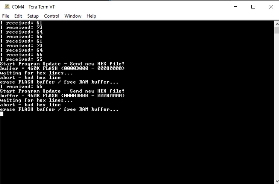
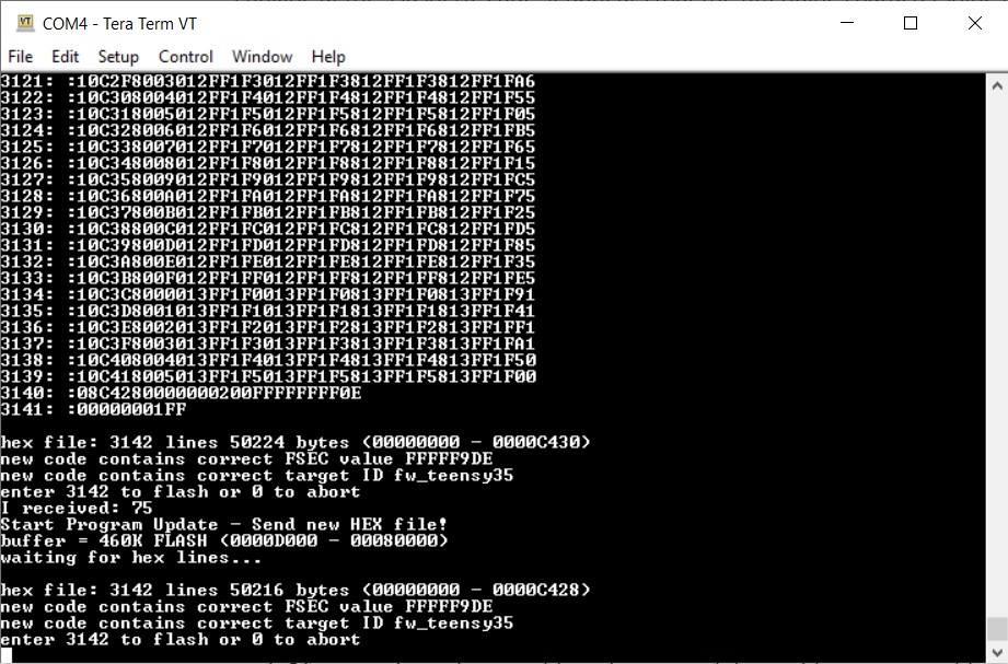
And here is some of the output:
|
1 2 3 4 5 6 7 8 9 10 11 12 13 14 15 16 17 18 19 20 21 22 23 24 25 26 27 28 29 |
I received: 55 Start Program Update - Send new HEX file! buffer = 460K FLASH (0000D000 - 00080000) waiting for hex lines... hex file: 3194 lines 51048 bytes (00000000 - 0000C768), 13742 Msec new code contains correct FSEC value FFFFF9DE new code contains correct target ID fw_teensy35 enter 3194 to flash or 0 to abort Msec ADVal TotVolts TotAmps 2500 475 1.53 1.53 2700 465 1.50 1.50 2900 466 1.50 1.50 3100 499 1.61 1.61 3300 32 0.10 0.10 3500 459 1.48 1.48 3700 323 1.04 1.04 3900 473 1.53 1.53 4100 9 0.03 0.03 4300 317 1.02 1.02 4500 467 1.51 1.51 4700 460 1.48 1.48 4900 466 1.50 1.50 5100 262 0.85 0.85 5300 28 0.09 0.09 5500 467 1.51 1.51 5700 471 1.52 1.52 5900 469 1.51 1.51 6100 471 1.52 1.52 |
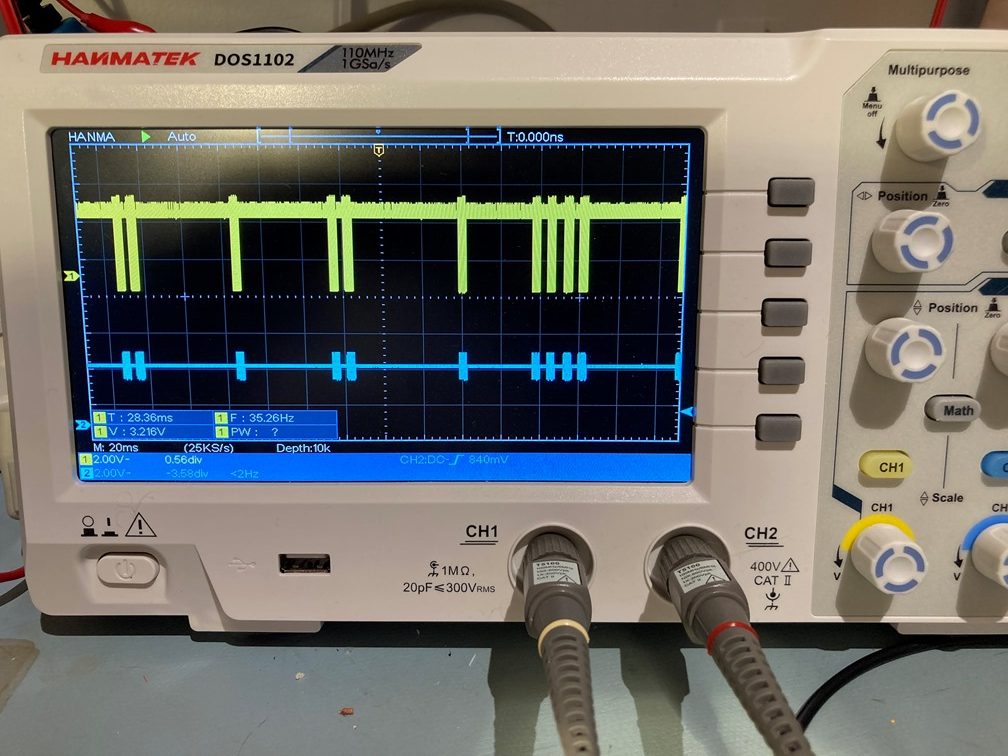
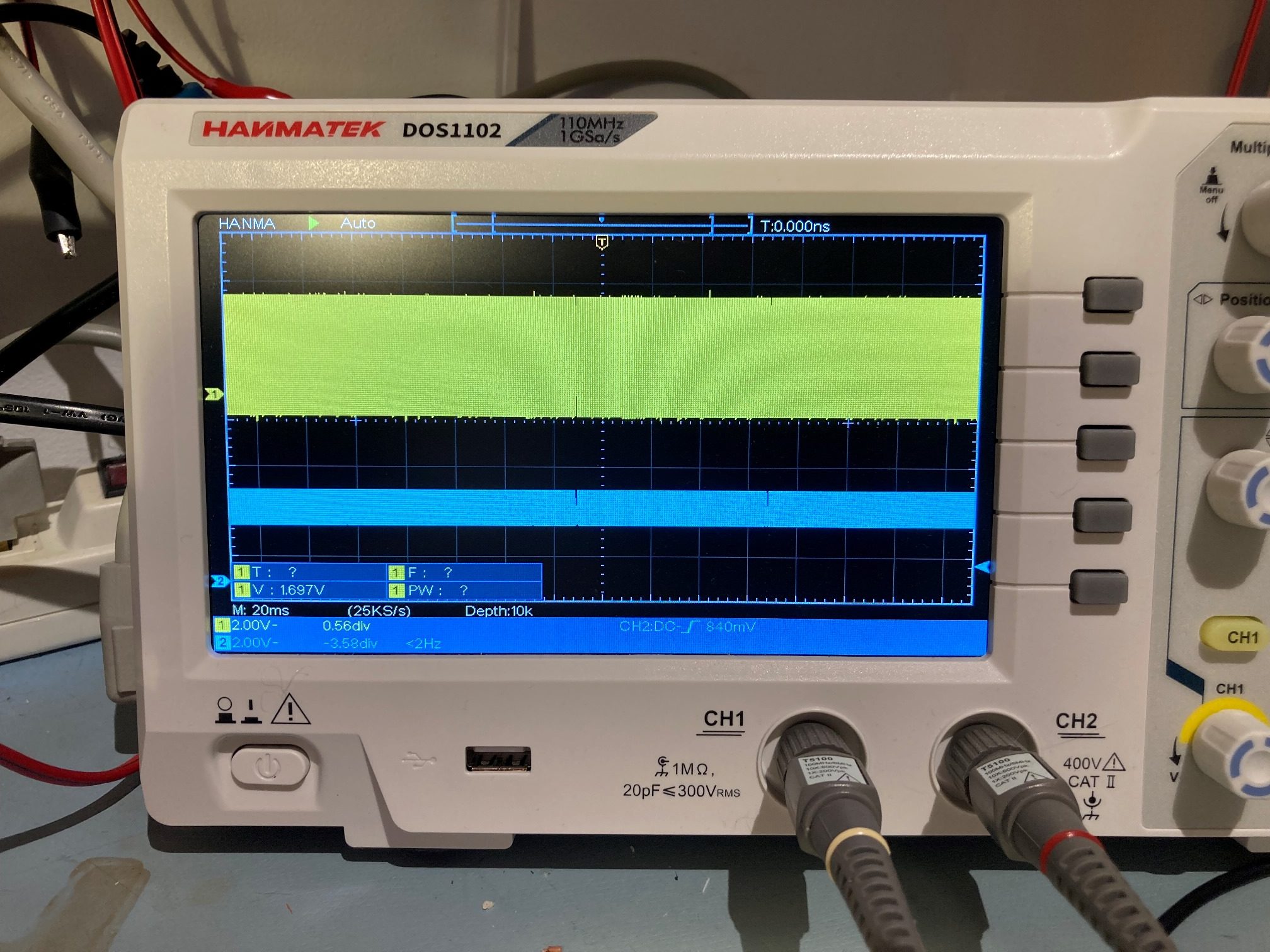
With this setup I noticed there were a lot of ‘dropouts’ in the sensor outputs, so I added a 1uF cap between the sensor Vout and GND. This seemed to cure the dropouts as shown in the next output snippet (after some charging time resulting in lower charging current)
|
1 2 3 4 5 6 7 8 9 10 11 12 13 14 15 16 17 18 19 20 21 22 23 24 25 26 27 28 29 30 31 32 33 34 35 36 37 38 39 40 41 |
Msec ADVal TotVolts TotAmps 2500 265 0.85 0.85 2700 263 0.85 0.85 2900 266 0.86 0.86 3100 267 0.86 0.86 3300 269 0.87 0.87 3500 265 0.85 0.85 3700 266 0.86 0.86 3900 264 0.85 0.85 4100 266 0.86 0.86 4300 269 0.87 0.87 4500 268 0.86 0.86 4700 268 0.86 0.86 4900 265 0.85 0.85 5100 267 0.86 0.86 5300 266 0.86 0.86 5500 265 0.85 0.85 5700 267 0.86 0.86 5900 265 0.85 0.85 6100 263 0.85 0.85 6300 264 0.85 0.85 6500 266 0.86 0.86 6700 262 0.85 0.85 6900 261 0.84 0.84 7100 263 0.85 0.85 7300 259 0.84 0.84 7500 262 0.85 0.85 7700 261 0.84 0.84 7900 262 0.85 0.85 8100 262 0.85 0.85 8300 261 0.84 0.84 8500 261 0.84 0.84 8700 262 0.85 0.85 8900 260 0.84 0.84 9100 261 0.84 0.84 9300 258 0.83 0.83 9500 262 0.85 0.85 9700 258 0.83 0.83 9900 257 0.83 0.83 10100 259 0.84 0.84 10300 261 0.84 0.84 |
04 November 2021 Update:
I installed two Pololu VNH5019 drivers onto the prototype bottom plate, and copied the associated motor support code from my latest Wall-E2 version. I modified ‘SetLeftMotorDirAndSpeed(bool bIsFwd, int speed)’ and ‘SetRightMotorDirAndSpeed(bool bIsFwd, int speed)’ for the VNH5019 pinout and truth table, and that was pretty much all I had to do. Then I copied all of ‘CheckForUserInput()’ from Wall-E2 (and added the ‘U/u’ case for OTA updates) so I could control the motor direction and speed via the OTA serial connection, and the motors and drivers behaved pretty much right away. Here’s a short video showing the action:
05 November 2021 Update
I finally got the new 200 x 230 mm aluminum chassis finished, as shown in the following photo:
10 November 2021 Update:
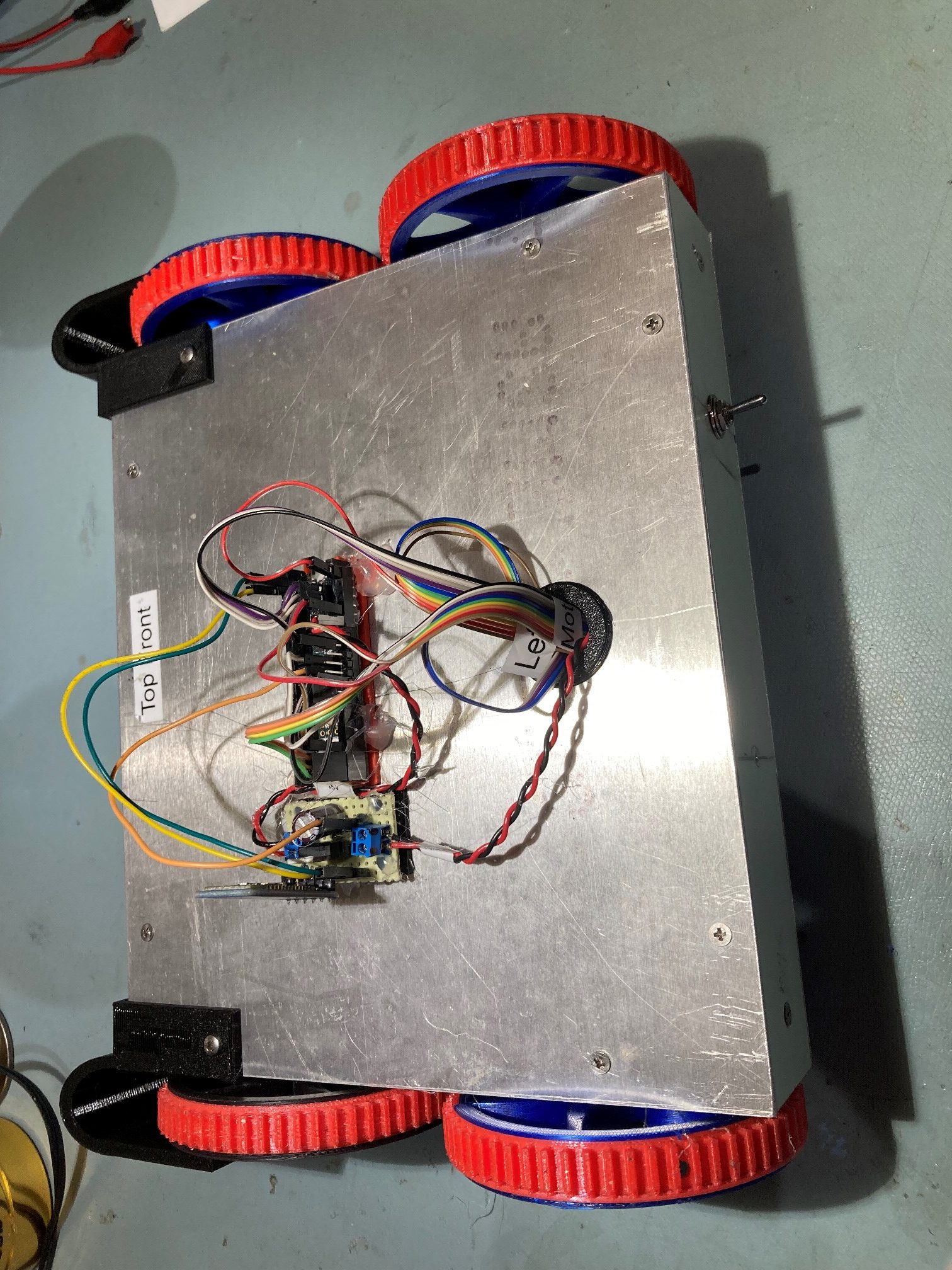
After getting the new aluminum chassis fabricated, it was time to start populating it with subsystems from the prototype chassis and from Wall-E2. As shown in the following photo, the next big milestone was to populate it with four Pololu D-20 motors, the battery/charger and 5V LDO regulator subsystems, and the two Pololu VNH5019 motor drivers from the proto chassis. With the addition of four 3D printed wheels/tires from Wall-E2, and Wall-E3 was officially ‘mobile’!
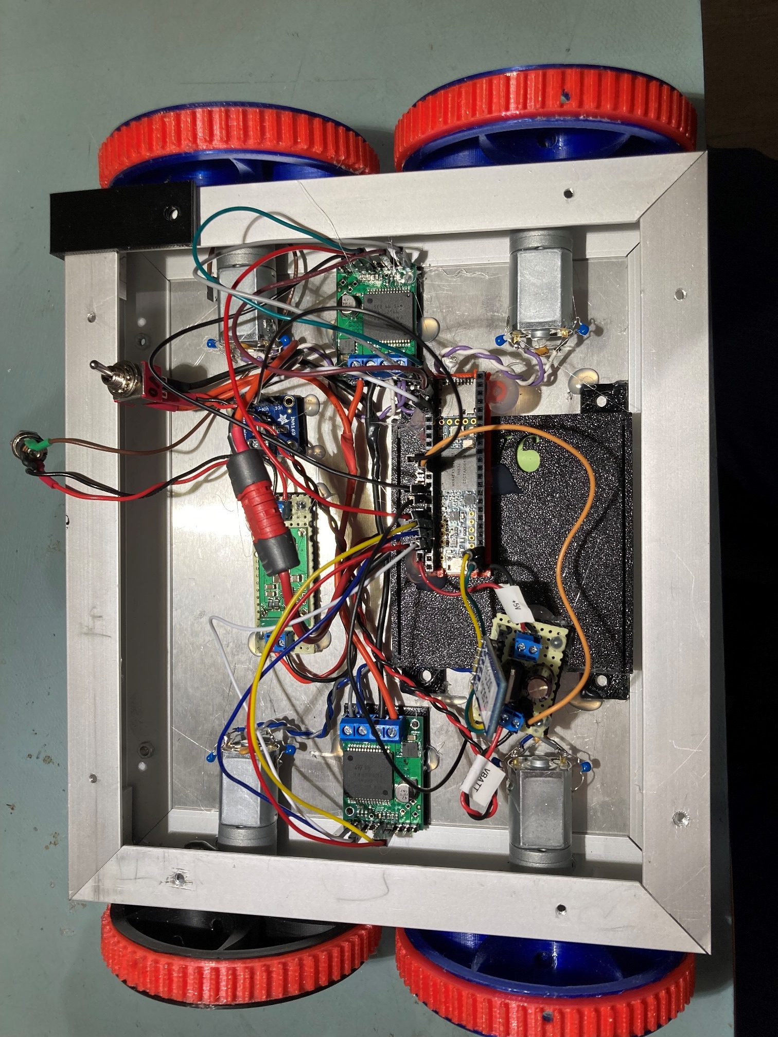
As can be seen above, the Teensy 3.5 controller and its companion 5V LDO regulator board/HC-05 Bluetooth module were simply hot-glued to the battery pack for initial testing; they will be moved to the top plate next.
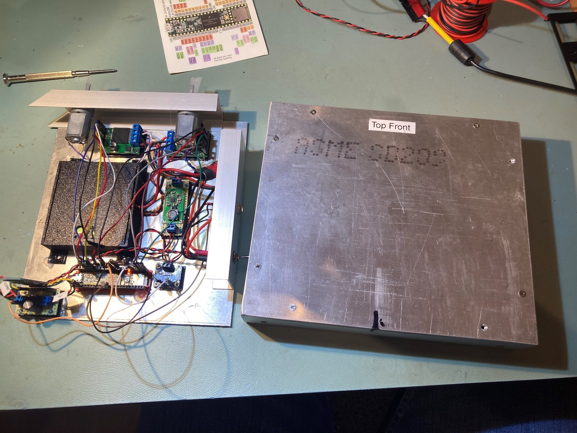
After successful movement tests with the above arrangement (see the companion post), the next step was to install the Teensy 3.5 controller and the LDO/HC-05 module on the top plate, and permanently install the charging connector and the ON/OFF switch. I decided that a single hole punched into the center rear of the top plate would suffice for bringing necessary wiring up from the internal battery/motor bay onto the top plate, and placing the hole toward the rear would allow the top plate to be removed and placed upside down at the back of the chassis to allow access to the battery/motor bay as needed. As shown in the following photo, the top plate is secured upside-down on the main chassis by two of the normal mounting screws, thus keeping the top-plate-mounted subsystems from contacting the ground.
Also note that the motor/battery bay is much cleaner than the Wall-E2 layout, even though both motor drivers are in this bay rather than mounted to the top plate as they are for Wall-E2. The next photos below show the chassis closed up with the Teensy 3.5 and the 5V LDO module mounted on the top plate, with the charging connector and the ON/OFF switch permanently installed.
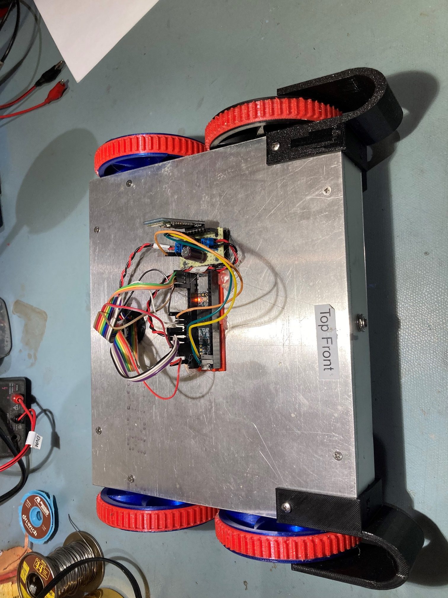
Front & rear aspect views of the ‘closed’ chassis
After getting everything closed up, I re-ran the ‘spin turn’ trials, as shown below:
At this point, there are only three significant modules (the MPU6050 IMU, the ‘Run Current’ 1NA169 high-side current sensor, and the charging station beacon homing module) remaining to install on the top plate. The first step will be to install and test the MPU6050, as that will give Wall-E3 the capability to do angle-controlled turns.
20 November 2021 Update:
As described in the companion post to this one, my plan is to move forward with the Teensy program (Teensy_MPU6050_DMP6_V3.ino) and the older I2CDevlib/MPU6050 library versions while waiting for Jeff Rowberg and company to figure out why the current versions of this library are no longer compatible with the Teensy 3.x line of microcontrollers.
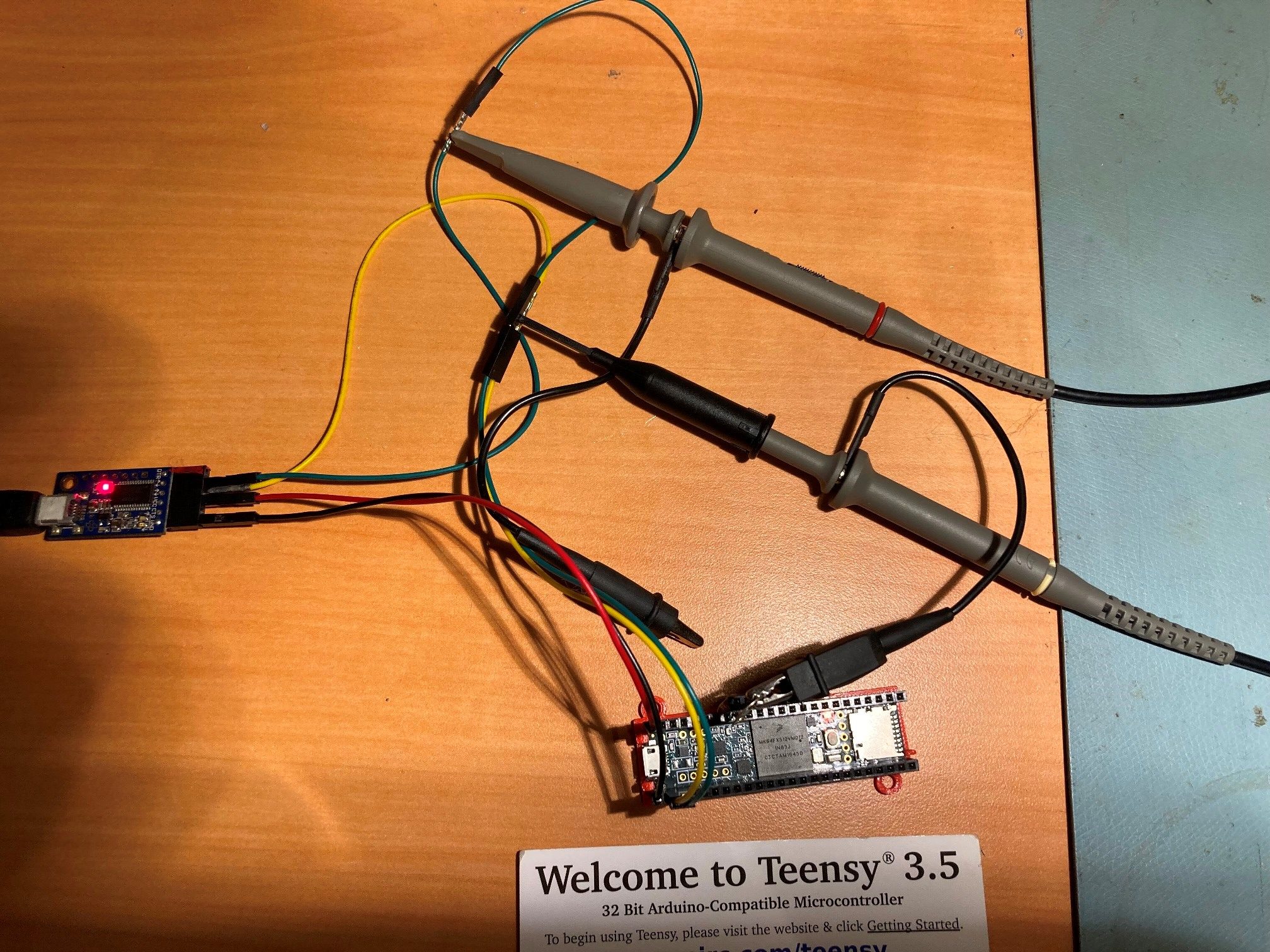
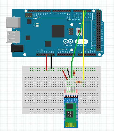
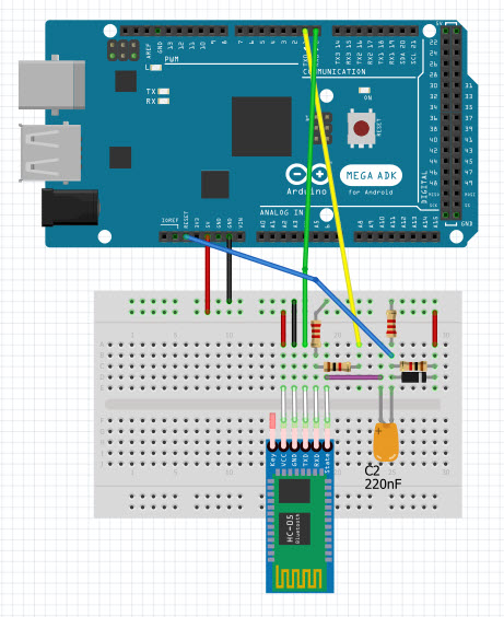
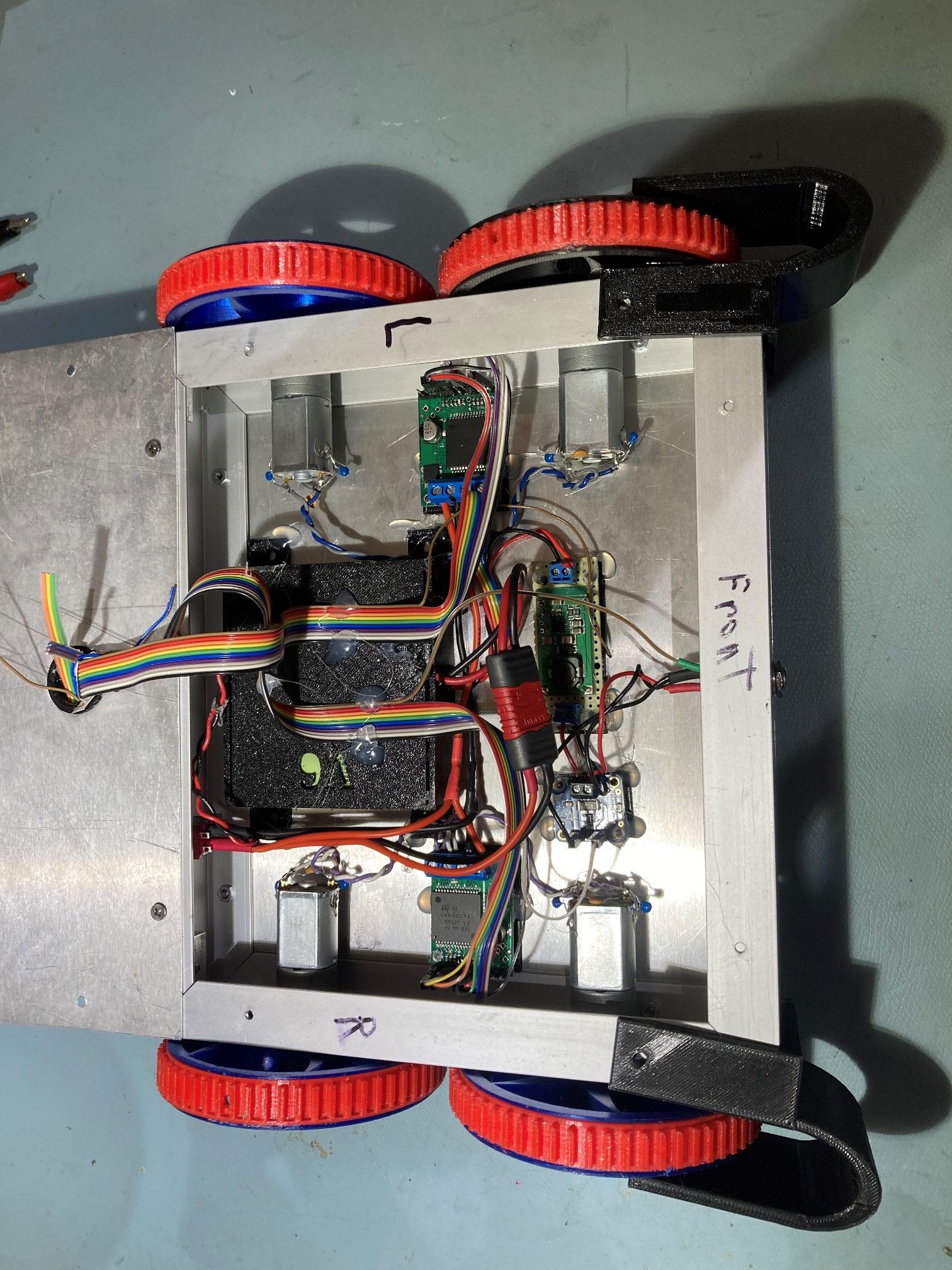
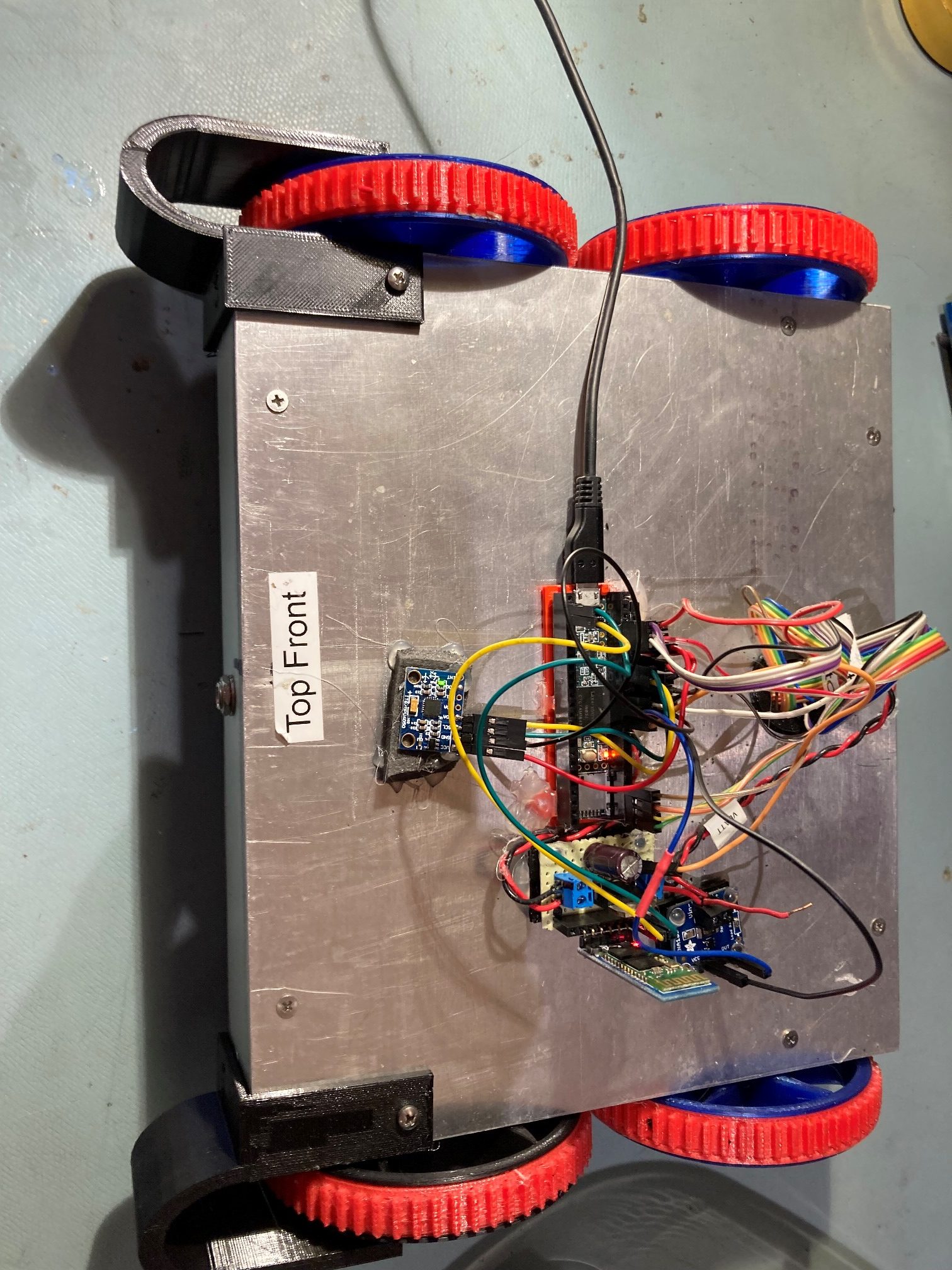
The first step in this process is to remove the Arduino UNO/Wixel Shield module from the robot, and get the already-installed Teensy 3.5 talking to the already-installed MPU6050 module using the above mentioned Teensy_MPU6050_DMP6_V3.ino and the older I2CDevlib/MPU6050 library versions. Here’s the hardware layout:
And here’s some output from Teensy_MPU6050_DMP6_V3.ino showing a ‘live’ connection to the MPU6050:
|
1 2 3 4 5 6 7 8 9 10 11 12 13 14 15 16 17 18 19 20 21 22 23 24 25 26 27 28 29 30 31 32 33 34 35 36 37 38 39 40 41 42 43 44 45 46 47 48 49 50 51 52 53 54 55 56 57 58 59 60 61 62 63 64 65 66 67 68 |
Opening port Port open In Setup Testing device connections... getDeviceID() returns 0X34 MPU6050 connection successful Initializing DMP... Enabling DMP... DMP ready! Waiting for MPU6050 drift rate to settle... MPU6050 Ready at 3.76 Sec 3973 0.19 4173 0.49 4375 0.80 4575 1.09 4775 1.35 4975 1.58 5175 1.78 5375 1.96 5575 2.12 5775 2.28 5975 2.43 6175 2.57 6375 2.66 6587 1.04 6764 -3.44 6964 -10.12 7164 -13.49 7364 -19.00 7564 -23.03 7768 -21.80 7968 -16.39 8168 -8.59 8368 0.90 8568 10.14 8768 15.36 8968 15.97 9168 14.49 9368 14.45 9568 13.57 9768 6.65 9970 -4.99 10170 -15.33 10370 -24.65 10570 -28.25 10770 -25.79 10970 -23.11 11170 -14.95 11370 -3.79 11570 9.58 11770 19.47 11973 23.61 12173 22.41 12373 21.69 12573 21.23 12773 20.94 12973 20.76 13173 20.67 13373 20.65 13573 20.66 13773 20.71 13975 20.77 14175 20.85 14375 20.95 14575 21.05 14775 21.15 Port closed |
At this point, we have demonstrated we can talk to the MPU6050 using Jeff Rowberg’s (old) I2CDevlib library and can pull off yaw values, so we should also be able to do the same turn-rate-controlled turns as before.
So now I have a Teensy project (Teensy_MPU6050_DMP6_V3) that demonstrates a working interface to the MPU6050, a prior project (T35_WallE3_V1) that demonstrated Teensy OTA updates using an HC-05 Bluetooth module, and a Teensy project demonstrating turn-rate controlled turns using the MPU6050 (T35_MPU6050_Demo_V2). The next step is to create yet another new project, this time cleverly called ‘T35_WallE3_V2’, to merge all these features into one project, and then hopefully proceed from there.
When I created the T35_WallE3_V2 project, the first thing I did was copy in T35_WallE3_V1.ino and supporting files, and then I tested it to make sure everything was OK. However, this project wouldn’t connect to the MPU6050 even though I was sure it was using the older I2CDevlib files. After a very careful comparison, I found there were a very few differences. When I instead used the support files from my Teensy_MPU6050_DMP6_V3 project, then T35_WallE3_V2 was able to connect to the MPU6050. The i2Cdev.h/cpp files were essentially identical. The MPU6050.h/cpp files were essentially identical. The MPU6050_6Axis_MotionApps_V6_12.h files were essentially identical, so I’m not really sure why the magic happened — but it did!
So now the T35_WallE3_V2 talks to the MPU6050. Next I enabled ‘board.txt’ and verified that I can still do OTA firmware updates.
21 November 2021 (an almost palindromic date 21_11_21) Update:
After verifying OTA update capability with T35_WallE3_V2, I started porting in turn-rate control code from the Teensy_MPU6050_DMP6_V3 project, consisting mainly of the PID values empirically found in the companion ‘form-factor’ post, and the PIDCalcs() function.
- Replaced T35_WallE3_V2 ‘CheckForUserInput()’ with version from T35_MPU6050_Demo_V2
- Replaced T35_WallE3_V2 ‘PIDCalcs()’ with version from T35_MPU6050_Demo_V2
- Replaced T35_WallE3_V2 ‘SpinTurn()’ with version from T35_MPU6050_Demo_V2 and added TURN_START_SPEED constant.
- Updated TurnRate_Kp/Ki/Kd to 1.8/1.0/0.4
22 November 2021 Update:
At this point I have T35_WallE3_V2 to the point where I can do OTA firmware updates via the HC-05 Bluetooth link, and I can remotely command CW & CCW turns, forward and backward, speed up/down. Here’s the snapshot of the code at this point.
|
1 2 3 4 5 6 7 8 9 10 11 12 13 14 15 16 17 18 19 20 21 22 23 24 25 26 27 28 29 30 31 32 33 34 35 36 37 38 39 40 41 42 43 44 45 46 47 48 49 50 51 52 53 54 55 56 57 58 59 60 61 62 63 64 65 66 67 68 69 70 71 72 73 74 75 76 77 78 79 80 81 82 83 84 85 86 87 88 89 90 91 92 93 94 95 96 97 98 99 100 101 102 103 104 105 106 107 108 109 110 111 112 113 114 115 116 117 118 119 120 121 122 123 124 125 126 127 128 129 130 131 132 133 134 135 136 137 138 139 140 141 142 143 144 145 146 147 148 149 150 151 152 153 154 155 156 157 158 159 160 161 162 163 164 165 166 167 168 169 170 171 172 173 174 175 176 177 178 179 180 181 182 183 184 185 186 187 188 189 190 191 192 193 194 195 196 197 198 199 200 201 202 203 204 205 206 207 208 209 210 211 212 213 214 215 216 217 218 219 220 221 222 223 224 225 226 227 228 229 230 231 232 233 234 235 236 237 238 239 240 241 242 243 244 245 246 247 248 249 250 251 252 253 254 255 256 257 258 259 260 261 262 263 264 265 266 267 268 269 270 271 272 273 274 275 276 277 278 279 280 281 282 283 284 285 286 287 288 289 290 291 292 293 294 295 296 297 298 299 300 301 302 303 304 305 306 307 308 309 310 311 312 313 314 315 316 317 318 319 320 321 322 323 324 325 326 327 328 329 330 331 332 333 334 335 336 337 338 339 340 341 342 343 344 345 346 347 348 349 350 351 352 353 354 355 356 357 358 359 360 361 362 363 364 365 366 367 368 369 370 371 372 373 374 375 376 377 378 379 380 381 382 383 384 385 386 387 388 389 390 391 392 393 394 395 396 397 398 399 400 401 402 403 404 405 406 407 408 409 410 411 412 413 414 415 416 417 418 419 420 421 422 423 424 425 426 427 428 429 430 431 432 433 434 435 436 437 438 439 440 441 442 443 444 445 446 447 448 449 450 451 452 453 454 455 456 457 458 459 460 461 462 463 464 465 466 467 468 469 470 471 472 473 474 475 476 477 478 479 480 481 482 483 484 485 486 487 488 489 490 491 492 493 494 495 496 497 498 499 500 501 502 503 504 505 506 507 508 509 510 511 512 513 514 515 516 517 518 519 520 521 522 523 524 525 526 527 528 529 530 531 532 533 534 535 536 537 538 539 540 541 542 543 544 545 546 547 548 549 550 551 552 553 554 555 556 557 558 559 560 561 562 563 564 565 566 567 568 569 570 571 572 573 574 575 576 577 578 579 580 581 582 583 584 585 586 587 588 589 590 591 592 593 594 595 596 597 598 599 600 601 602 603 604 605 606 607 608 609 610 611 612 613 614 615 616 617 618 619 620 621 622 623 624 625 626 627 628 629 630 631 632 633 634 635 636 637 638 639 640 641 642 643 644 645 646 647 648 649 650 651 652 653 654 655 656 657 658 659 660 661 662 663 664 665 666 667 668 669 670 671 672 673 674 675 676 677 678 679 680 681 682 683 684 685 686 687 688 689 690 691 692 693 694 695 696 697 698 699 700 701 702 703 704 705 706 707 708 709 710 711 712 713 714 715 716 717 718 719 720 721 722 723 724 725 726 727 728 729 730 731 732 733 734 735 736 737 738 739 740 741 742 743 744 745 746 747 748 749 750 751 752 753 754 755 756 757 758 759 760 761 762 763 764 765 766 767 768 769 770 771 772 773 774 775 776 777 778 779 780 781 782 783 784 785 786 787 788 789 790 791 792 793 794 795 796 797 798 799 800 801 802 803 804 805 806 807 808 809 810 811 812 813 814 815 816 817 818 819 820 821 822 823 824 825 826 827 828 829 830 831 832 833 834 835 836 837 838 839 840 841 842 843 844 845 846 847 848 849 850 851 852 853 854 855 856 857 858 859 860 861 862 863 864 865 866 867 868 869 870 871 872 873 874 875 876 877 878 879 880 881 882 883 884 885 886 887 888 889 890 891 892 893 894 895 896 897 898 899 900 901 902 903 904 905 906 907 908 909 910 911 912 913 914 915 916 917 918 919 920 921 922 923 924 925 926 927 928 929 930 931 932 933 934 935 936 937 938 939 940 941 942 943 944 945 946 947 948 949 950 951 952 953 954 955 956 957 958 959 960 961 962 963 964 965 966 967 968 969 970 971 972 973 974 975 976 977 978 979 980 981 982 983 984 985 986 987 988 989 990 991 992 993 994 995 996 997 998 999 1000 1001 1002 1003 1004 1005 1006 1007 1008 1009 1010 1011 1012 1013 1014 1015 1016 1017 1018 1019 1020 1021 1022 1023 1024 1025 1026 1027 1028 1029 1030 1031 1032 1033 1034 1035 1036 1037 1038 1039 1040 1041 1042 1043 1044 1045 1046 1047 1048 1049 1050 1051 1052 1053 1054 1055 1056 1057 1058 1059 1060 1061 1062 1063 1064 1065 1066 1067 1068 1069 1070 1071 1072 1073 1074 1075 1076 1077 1078 1079 1080 1081 1082 1083 1084 1085 1086 1087 1088 1089 1090 1091 1092 1093 1094 1095 1096 1097 1098 1099 1100 1101 1102 1103 1104 1105 1106 1107 1108 1109 1110 1111 1112 1113 1114 1115 1116 1117 1118 1119 1120 1121 1122 1123 1124 1125 1126 1127 1128 1129 1130 1131 1132 1133 1134 1135 1136 1137 1138 1139 1140 1141 1142 1143 1144 1145 1146 1147 1148 1149 1150 1151 1152 1153 1154 1155 1156 1157 1158 1159 1160 1161 1162 1163 1164 1165 1166 1167 1168 1169 1170 1171 1172 1173 1174 1175 1176 1177 1178 1179 1180 1181 1182 1183 1184 1185 1186 1187 1188 1189 1190 1191 1192 1193 1194 1195 1196 1197 1198 1199 1200 1201 1202 1203 1204 1205 1206 1207 1208 1209 1210 1211 1212 1213 1214 1215 1216 1217 1218 1219 1220 1221 1222 1223 1224 1225 1226 1227 1228 1229 1230 1231 1232 1233 1234 1235 1236 1237 1238 1239 1240 1241 1242 1243 1244 1245 1246 1247 1248 1249 1250 1251 1252 1253 1254 1255 1256 1257 1258 1259 1260 1261 1262 1263 1264 1265 1266 1267 1268 1269 1270 1271 1272 1273 1274 1275 1276 1277 1278 1279 1280 1281 1282 1283 1284 1285 1286 1287 1288 1289 1290 1291 1292 1293 1294 1295 1296 1297 1298 1299 1300 1301 1302 1303 1304 1305 1306 1307 1308 1309 1310 1311 1312 1313 1314 1315 1316 1317 1318 1319 1320 1321 1322 1323 1324 1325 1326 1327 1328 1329 1330 1331 1332 1333 1334 1335 1336 1337 1338 1339 1340 1341 1342 1343 1344 1345 1346 1347 1348 1349 1350 1351 1352 1353 1354 1355 1356 1357 1358 1359 1360 1361 1362 1363 1364 1365 1366 1367 1368 1369 1370 1371 1372 1373 1374 1375 1376 1377 1378 1379 1380 1381 1382 1383 1384 1385 1386 1387 1388 1389 1390 1391 1392 1393 1394 1395 1396 1397 1398 1399 1400 1401 1402 1403 1404 1405 1406 1407 1408 1409 1410 1411 1412 1413 1414 1415 1416 1417 1418 1419 1420 1421 1422 1423 1424 1425 1426 1427 1428 1429 1430 1431 1432 1433 1434 1435 1436 1437 1438 1439 1440 1441 1442 1443 1444 1445 1446 1447 1448 1449 1450 1451 1452 1453 1454 1455 1456 1457 1458 1459 1460 1461 1462 1463 1464 1465 1466 1467 1468 1469 1470 1471 1472 1473 1474 1475 1476 1477 1478 1479 1480 1481 1482 1483 1484 1485 1486 1487 1488 1489 1490 1491 1492 1493 1494 1495 1496 1497 1498 1499 1500 1501 1502 1503 1504 1505 1506 1507 1508 1509 1510 1511 1512 1513 1514 1515 1516 1517 1518 1519 1520 1521 1522 1523 1524 1525 1526 1527 1528 1529 1530 1531 1532 1533 1534 1535 1536 1537 1538 1539 1540 1541 1542 1543 1544 1545 1546 1547 1548 1549 1550 1551 1552 1553 1554 1555 1556 1557 1558 1559 1560 1561 1562 1563 1564 1565 1566 1567 1568 1569 1570 1571 1572 1573 1574 1575 1576 1577 1578 1579 1580 1581 1582 1583 1584 1585 1586 1587 1588 1589 1590 1591 1592 1593 1594 1595 1596 1597 1598 1599 1600 1601 1602 1603 1604 1605 1606 1607 1608 1609 1610 1611 1612 1613 1614 1615 1616 1617 1618 1619 1620 1621 1622 1623 1624 1625 1626 1627 1628 1629 1630 1631 1632 1633 1634 1635 1636 1637 1638 1639 1640 1641 1642 1643 1644 1645 1646 1647 1648 1649 1650 1651 1652 1653 1654 1655 1656 1657 1658 1659 1660 1661 1662 1663 1664 1665 1666 1667 1668 1669 1670 1671 1672 1673 1674 1675 1676 1677 1678 1679 1680 1681 1682 1683 1684 1685 1686 1687 1688 1689 1690 1691 1692 1693 1694 1695 1696 1697 1698 1699 1700 1701 1702 1703 1704 1705 1706 1707 1708 1709 1710 1711 1712 1713 1714 1715 1716 1717 1718 1719 1720 1721 1722 1723 1724 1725 1726 1727 1728 1729 1730 1731 1732 1733 1734 1735 1736 1737 1738 1739 1740 1741 1742 1743 1744 1745 1746 1747 1748 1749 1750 1751 1752 1753 1754 1755 1756 1757 1758 1759 1760 1761 1762 1763 1764 1765 1766 1767 1768 1769 1770 1771 1772 1773 1774 1775 1776 1777 1778 1779 1780 1781 1782 1783 1784 1785 1786 1787 1788 1789 1790 1791 1792 1793 1794 1795 1796 1797 1798 1799 1800 1801 1802 1803 1804 1805 1806 1807 1808 1809 1810 1811 1812 1813 1814 1815 1816 1817 1818 1819 1820 1821 1822 1823 1824 1825 1826 1827 1828 1829 1830 1831 1832 1833 1834 1835 1836 1837 1838 1839 1840 1841 1842 1843 1844 1845 1846 1847 1848 1849 1850 1851 1852 1853 1854 1855 1856 1857 1858 1859 1860 1861 1862 1863 1864 1865 1866 1867 1868 1869 1870 1871 1872 1873 1874 1875 1876 1877 1878 1879 1880 1881 1882 1883 1884 1885 1886 1887 1888 1889 1890 1891 1892 1893 1894 1895 1896 1897 1898 1899 1900 1901 1902 1903 |
/* Name: T35_WallE3_V2.ino Created: 11/20/2021 4:41:25 PM Author: FRANKNEWXPS15\Frank */ /* Name: T35_WallE3_V1.ino Created: 10/25/2021 2:37:04 PM Author: FRANKNEWXPS15\Frank 10/30/21 - Added TeensyOTADemo code for basic OTA updates */ /* Name: TeensyOTADemo.ino Created: 10/9/2021 11:18:19 AM Author: FRANKNEWXPS15\Frank This program demonstrates the use of 'board.txt' post-build instructions in conjunction with a small C# command-line program for seamless 'over-the-air' (OTA) firmware update for Teensy modules. Implementation of OTA update requires that Joe Pasquariello's 'FlasherX' code be added to the Teensy sketch as it is below, and some code to allow an external serial communications program to trigger the update process. In the demo sketch below, the 'FlasherX' additions are the '#include FlasherTxx.h' line and the addition of the FlasherX specific code at the bottom. The trigger mechanism is provided by the 'CheckForUserInput();' call in loop. If the ASCII code for 'U' or 'u' is present on Serial1, the update process will be launched. */ #pragma region INCLUDES #include "FlashTxx.h" // TLC/T3x/T4x flash primitives #include <elapsedMillis.h> #include "MPU6050_6Axis_MotionApps_V6_12.h" //changed to this version 10/05/19 #pragma endregion Includes #pragma region DEFINES //02/29/16 hardware defines //#define NO_MOTORS //#define IR_HOMING_ONLY //#define NO_LIDAR //#define NO_PINGS //#define NO_IRDET //added 04/05/17 for daytime in-atrium testing (too much ambient IR) //#define DISTANCES_ONLY //added 11/14/18 to just display distances in infinite loop #define NO_STUCK //added 03/10/19 to disable 'stuck' detection //#define BATTERY_DISCHARGE //added 03/04/20 to discharge battery safely #define NO_POST //added 04/12/20 to skip all the POST checks //11/07/2020 moved all I2C Address declarations here #define IRDET_I2C_ADDR 0x08 #define MPU6050_I2C_ADDR 0x68 #pragma endregion Program #Defines #pragma region PRE_SETUP MPU6050 mpu(MPU6050_I2C_ADDR); elapsedMillis MsecSinceLastLEDToggle; //used for LED blink timer const double ADC_REF_VOLTS = 3.3; //teensy default for analog inputs const double AmpsPerVolt = 1.00; //default 10K Rs const int MAX_AD_COUNT = 1023; const double VoltsPerCount = ADC_REF_VOLTS / MAX_AD_COUNT; //Battery constants const float ZENER_VOLTAGE_OFFSET = 5.84; //measured zener voltage #pragma region PIN ASSIGNMENTS //vvvvvvvvvvvvvvvvvvvvvvvvvvvvvvvvvvvvvvvvvvvvvvvvvvvvvvvvvvvvvv// //=================== START PIN ASSIGNMENTS ===================// //vvvvvvvvvvvvvvvvvvvvvvvvvvvvvvvvvvvvvvvvvvvvvvvvvvvvvvvvvvvvvv// #pragma region MOTOR_PINS //11/04/21 Now using Pololu VNH5019 drivers for all 4 motors const int InA_Left = 22; const int InB_Left = 21; const int Spd_Left = 23; const int InA_Right = 34; const int InB_Right = 33; const int Spd_Right = 35; #pragma endregion Motor Pin Assignments const int ChgConnectPin = 36; const int ItotPin = A1; const int IRunPin = A2; const int BATT_MON_PIN = A0; #pragma endregion PIN ASSIGNMENTS #pragma region MOTOR_PARAMETERS //drive wheel speed parameters const int MOTOR_SPEED_FULL = 200; //range is 0-255 const int MOTOR_SPEED_MAX = 255; //range is 0-255 const int MOTOR_SPEED_HALF = 127; //range is 0-255 const int MOTOR_SPEED_QTR = 75; //added 09/25/20 const int MOTOR_SPEED_LOW = 50; //added 01/22/15 const int MOTOR_SPEED_OFF = 0; //range is 0-255 const int MOTOR_SPEED_CAPTURE_OFFSET = 75; //added 06/21/20 for offset capture const int TURN_START_SPEED = MOTOR_SPEED_QTR; //added 11/14/21 //drive wheel direction constants const boolean FWD_DIR = true; const boolean REV_DIR = !FWD_DIR; const bool TURNDIR_CCW = true; const bool TURNDIR_CW = false; //Motor direction variables bool bIsForwardDir = true; //default is foward direction #pragma endregion Motor Parameters #pragma region MPU6050_SUPPORT uint8_t mpuIntStatus; // holds actual interrupt status byte from MPU. Used in Homer's Overflow routine uint8_t devStatus; // return status after each device operation (0 = success, !0 = error) uint16_t packetSize; // expected DMP packet size (default is 42 bytes) uint16_t fifoCount; // count of all bytes currently in FIFO uint8_t fifoBuffer[64]; // FIFO storage buffer // orientation/motion vars Quaternion q; // [w, x, y, z] quaternion container VectorInt16 aa; // [x, y, z] accel sensor measurements VectorInt16 aaReal; // [x, y, z] gravity-free accel sensor measurements VectorInt16 aaWorld; // [x, y, z] world-frame accel sensor measurements VectorFloat gravity; // [x, y, z] gravity vector float euler[3]; // [psi, theta, phi] Euler angle container float ypr[3]; // [yaw, pitch, roll] yaw/pitch/roll container and gravity vector int GetPacketLoopCount = 0; int OuterGetPacketLoopCount = 0; //MPU6050 status flags bool bMPU6050Ready = true; bool dmpReady = false; // set true if DMP init was successful volatile float IMUHdgValDeg = 0; //updated by UpdateIMUHdgValDeg()//11/02/20 now updated in ISR const uint16_t MAX_GETPACKET_LOOPS = 100; //10/30/19 added for backup loop exit condition in GetCurrentFIFOPacket() uint8_t GetCurrentFIFOPacket(uint8_t* data, uint8_t length, uint16_t max_loops = MAX_GETPACKET_LOOPS); //prototype here so can define a default param bool bFirstTime = true; //#define MPU6050_CCW_INCREASES_YAWVAL //added 12/05/19 commented out 11/22/21 as now the MPU6050 module is mounted 'Z-up' #pragma endregion MPU6050 Support #pragma region HEADING_AND_RATE_BASED_TURN_PARAMETERS elapsedMillis MsecSinceLastTurnRateUpdate; const int MAX_SPIN_MOTOR_SPEED = 250; const int MIN_SPIN_MOTOR_SPEED = 50; const int TURN_RATE_UPDATE_INTERVAL_MSEC = 30; //30 mSec is as fast as it can go double TurnRateOutput; double TurnRateSetPoint_DPS; double Ival = 0; double lastErr = 0; double lastTurnRateVal_DPS; double TurnRateVal_DPS; double Prev_HdgDeg = 0; float tgt_deg; float timeout_sec; //11/16/21 almost perfect for 45 deg/sec, 100mSec //11/17/21 and pretty good for 90 deg/sec too! double TurnRate_Kp = 1.8; double TurnRate_Ki = 1.0; double TurnRate_Kd = 0.4; //ported from FourWD_PulseTurnRateTest.ino double TurnRatePIDOutput; //06/02/ const float HDG_NEAR_MATCH_VAL = 0.8; //slow the turn down here const float HDG_FULL_MATCH_VAL = 0.99; //stop the turn here //rev 06/01/21 const float HDG_MIN_MATCH_VAL = 0.6; //added 09/08/18: don't start checking slope until turn is well started #pragma endregion HEADING_AND_RATE_BASED_TURN_PARAMETERS #pragma region OTA UPDATE //****************************************************************************** // hex_info_t struct for hex record and hex file info //****************************************************************************** typedef struct { // char* data; // pointer to array allocated elsewhere unsigned int addr; // address in intel hex record unsigned int code; // intel hex record type (0=data, etc.) unsigned int num; // number of data bytes in intel hex record uint32_t base; // base address to be added to intel hex 16-bit addr uint32_t min; // min address in hex file uint32_t max; // max address in hex file int eof; // set true on intel hex EOF (code = 1) int lines; // number of hex records received } hex_info_t; void read_ascii_line(Stream* serial, char* line, int maxbytes); int parse_hex_line(const char* theline, char* bytes, unsigned int* addr, unsigned int* num, unsigned int* code); int process_hex_record(hex_info_t* hex); void update_firmware(Stream* serial, uint32_t buffer_addr, uint32_t buffer_size); uint32_t buffer_addr, buffer_size; //09/20/21 copied from FlasherX - loop() #pragma endregion OTA UPDATE #pragma endregion PRE_SETUP void setup() { Serial.begin(115200); delay(2000); //10/06/21 - just use fixed delay instead Serial1.begin(115200); //used HC-05 'AT' commands to set this speed //while (!Serial1) {} delay(2000); //11/20/21 use fixed delay instead of waiting Wire.begin(I2C_MASTER, 0x00, I2C_PINS_18_19, I2C_PULLUP_EXT, 400000); //DEBUG!! if (Serial) { Serial.printf("Serial = %p, Serial1 = %p\n", &Serial, &Serial1); } //DEBUG!! // //DEBUG!! if (Serial1) { Serial.printf("Serial = %p, Serial1 = %p\n", &Serial, &Serial1); } //DEBUG!! #pragma region PIN INITIALIZATION pinMode(LED_BUILTIN, OUTPUT); pinMode(ItotPin, INPUT); //I_total 1V/Amp pinMode(BATT_MON_PIN, INPUT); //Battery voltage monitor //motor pins pinMode(InA_Left, OUTPUT); pinMode(InB_Left, OUTPUT); pinMode(Spd_Left, OUTPUT); pinMode(InA_Right, OUTPUT); pinMode(InB_Right, OUTPUT); pinMode(Spd_Right, OUTPUT); #pragma endregion PIN INITIALIZATION #pragma region MPU6050 Serial.printf("\nChecking for MPU6050 IMU at I2C Addr 0x%x\n", MPU6050_I2C_ADDR); mpu.initialize(); // verify connection Serial.println(mpu.testConnection() ? F("MPU6050 connection successful") : F("MPU6050 connection failed")); float StartSec = 0; //used to time MPU6050 init Serial.println(F("Initializing DMP...")); devStatus = mpu.dmpInitialize(); // make sure it worked (returns 0 if successful) if (devStatus == 0) { // turn on the DMP, now that it's ready Serial.println(F("Enabling DMP...")); mpu.setDMPEnabled(true); // set our DMP Ready flag so the main loop() function knows it's okay to use it Serial.println(F("DMP ready! Waiting for MPU6050 drift rate to settle...")); dmpReady = true; // get expected DMP packet size for later comparison packetSize = mpu.dmpGetFIFOPacketSize(); Serial.printf("Just after MPU6050 Init\n"); Serial.printf("Calibrating...\n"); mpu.CalibrateGyro(); //using default value of 15 Serial.printf("Retrieving Calibration Values\n\n"); mpu.PrintActiveOffsets(); //loop heading display until stabilized Serial.printf("\nMsec\tHdg\n"); UpdateIMUHdgValDeg(); Prev_HdgDeg = IMUHdgValDeg; delay(100); UpdateIMUHdgValDeg(); Serial.printf("%lu\t%2.3f\t%2.3f\n", millis(), IMUHdgValDeg, Prev_HdgDeg); while (abs(IMUHdgValDeg - Prev_HdgDeg) > 0.1f) { Serial.printf("%lu\t%2.3f\n", millis(), IMUHdgValDeg); Prev_HdgDeg = IMUHdgValDeg; delay(100); UpdateIMUHdgValDeg(); } StartSec = millis() / 1000.f; Serial.printf("MPU6050 Ready at %2.2f Sec with delta = %2.3f\n", StartSec, IMUHdgValDeg - Prev_HdgDeg); bMPU6050Ready = true; delay(1000); } else //MPU6050 Init failed for some reason { // ERROR! // 1 = initial memory load failed // 2 = DMP configuration updates failed // (if it's going to break, usually the code will be 1) Serial.print(F("DMP Initialization failed (code ")); Serial.print(devStatus); Serial.println(F(")")); //08/29/21 print out battery voltage on failure float batV = GetBattVoltage(); Serial.printf("Battery Voltage = %2.2f\n", batV); bMPU6050Ready = false; } #pragma endregion MPU6050 analogReadAveraging(4); //applies to all analogRead() operations? MsecSinceLastLEDToggle = 0; Serial1.printf("Msec\tBattV\tTotAmps\tRunAmps\tHdgDeg\n"); } void loop() { //if (Serial1.available()) if (Serial1.available()||Serial.available()) { CheckForUserInput(); } if (MsecSinceLastLEDToggle >= 200) { MsecSinceLastLEDToggle -= 200; digitalWrite(LED_BUILTIN, !digitalRead(LED_BUILTIN)); //11/01/21 read I_tot value & cvt to current int ItotVal = analogRead(ItotPin); double ItotVolts = ItotVal * VoltsPerCount; double ItotAmps = ItotVolts * AmpsPerVolt; //Get battery voltage float calc_volts = GetBattVoltage(); //print out battery voltage & charge current Serial1.printf("%lu\t%2.2f\t%2.2f\n", millis(), calc_volts, ItotAmps); Serial.printf("%lu\t%2.2f\t%2.2f\n", millis(), calc_volts, ItotAmps); } } float GetBattVoltage() { //02/18/17 get corrected battery voltage. Voltage reading is 1/3 actual Vbatt value //int analog_batt_reading = GetAverageAnalogReading(BATT_MON_PIN, VOLTS_AVERAGE_NUMBER);//rev 03/01/19 to average readings int analog_batt_reading = analogRead(BATT_MON_PIN);//analogReadAveraging(4) in setup() does internal averaging float calc_volts = ZENER_VOLTAGE_OFFSET + ADC_REF_VOLTS * (double)analog_batt_reading / (double)MAX_AD_COUNT; ////DEBUG!! // Serial1.printf("a/d = %d, calc = %2.2f\n", analog_batt_reading,calc_volts); ////DEBUG!! return calc_volts; } //void CheckForUserInput() //{ // //Notes: // // 11/21/21 rev to accomodate cmd input from either serial, and output to both // // const int bufflen = 80; // char buff[bufflen]; // memset(buff, 0, bufflen); // float OffsetCm; // float Kp, Ki, Kd; // const char s[2] = ","; // char* token; // byte incomingByte = 0; //moved here 11/21/21 // // if (Serial.available() > 0) // { // // read the incoming byte: // //int incomingByte = Serial.read(); // incomingByte = Serial.read(); // // // say what you got: // Serial.print("I received: "); // Serial.println(incomingByte, HEX); //chg to HEX 02/18/20 // } // // //11/21/21 now input can come from Serial1 too // else if (Serial1.available() > 0) // { // // read the incoming byte: // incomingByte = Serial1.read(); // // // say what you got: // Serial1.print("I received: "); // Serial1.println(incomingByte, HEX); //chg to HEX 02/18/20 // } // // //11/21/21 incomingByte can come from either serial input // if (incomingByte != 0) // { // //02/18/20 experiment with multiple commands // switch (incomingByte) // { // case 0x55: //ASCII 'U' // case 0x75: //ASCII 'u' //#pragma region FIRMWARE UPDATE // Serial1.println(F("Start Program Update - Send new HEX file!")); // // // //09/20/21 copied from FlasherX - loop() // if (firmware_buffer_init(&buffer_addr, &buffer_size) == 0) // { // Serial1.printf("unable to create buffer\n"); // Serial1.flush(); // for (;;) {} // } // // Serial1.printf("buffer = %1luK %s (%08lX - %08lX)\n", // buffer_size / 1024, IN_FLASH(buffer_addr) ? "FLASH" : "RAM", // buffer_addr, buffer_addr + buffer_size); // // //09/20/21 clear the serial buffer // while (Serial1.available()) // { // Serial1.read(); // } // // // receive hex file via serial, write new firmware to flash, clean up, reboot // update_firmware(&Serial1, buffer_addr, buffer_size); // no return if success // // // return from update_firmware() means error or user abort, so clean up and // // reboot to ensure that static vars get boot-up initialized before retry // Serial1.printf("erase FLASH buffer / free RAM buffer...\n"); // firmware_buffer_free(buffer_addr, buffer_size); // Serial1.flush(); // REBOOT; // break; //#pragma endregion FIRMWARE UPDATE // case 0x43: //ASCII 'C' // case 0x63: //ASCII 'c' //#pragma region MANUALCONTROL // //enter infinite loop for direct remote control // Serial.println(F("ENTERING COMMAND MODE:")); // Serial.println(F("0 = 180 deg CCW Turn")); // Serial.println(F("1 = 180 deg CW Turn")); // Serial.println(F("A = Back to Auto Mode")); // Serial.println(F("S = Stop")); // Serial.println(F("F = Forward")); // Serial.println(F("R = Reverse")); // Serial.println(F("")); // Serial.println(F(" Faster")); // Serial.println(F("\t8")); // Serial.println(F("Left 4\t5 6 Right")); // Serial.println(F("\t2")); // Serial.println(F(" Slower")); // // Serial1.println(F("ENTERING COMMAND MODE:")); // Serial1.println(F("0 = 180 deg CCW Turn")); // Serial1.println(F("1 = 180 deg CW Turn")); // Serial1.println(F("A = Back to Auto Mode")); // Serial1.println(F("S = Stop")); // Serial1.println(F("F = Forward")); // Serial1.println(F("R = Reverse")); // Serial1.println(F("")); // Serial1.println(F(" Faster")); // Serial1.println(F("\t8")); // Serial1.println(F("Left 4\t5 6 Right")); // Serial1.println(F("\t2")); // Serial1.println(F(" Slower")); // // StopBothMotors(); // int speed = 0; // // bool bAutoMode = false; // while (!bAutoMode) // { // if (Serial.available() > 0) // { // // read the incoming byte: // incomingByte = Serial.read(); // // // say what you got: // Serial.print("I received: "); // Serial.println(incomingByte, HEX); //chg to HEX 02/18/20 // } // // //11/21/21 now input can come from Serial1 too // else if (Serial1.available() > 0) // { // // read the incoming byte: // incomingByte = Serial1.read(); // // // say what you got: // Serial1.print("I received: "); // Serial1.println(incomingByte, HEX); //chg to HEX 02/18/20 // } // // //11/21/21 incomingByte can come from either serial input // if (incomingByte != 0) // { // switch (incomingByte) // { // case 0x30: //Dec '0' // Serial.println(F("CCW 180 deg Turn")); // Serial1.println(F("CCW 180 deg Turn")); // SpinTurn(true, 180, 90); // MoveAhead(speed, speed); // break; // case 0x31: //Dec '1' // Serial.println(F("CW 180 deg Turn")); // Serial1.println(F("CW 180 deg Turn")); // SpinTurn(false, 180, 45); // break; // case 0x34: //Turn left 10 deg and keep moving // Serial.println(F("CCW 10 deg Turn")); // Serial1.println(F("CCW 10 deg Turn")); // SpinTurn(true, 10, 30); // // if (bIsForwardDir) // { // MoveAhead(speed, speed); // } // else // { // MoveReverse(speed, speed); // } // break; // case 0x36: //Turn right 10 deg and keep moving // Serial.print("CW 10 deg Turn\n"); // Serial1.print("CW 10 deg Turn\n"); // SpinTurn(false, 10, 30); // // //added 05/03/20 // if (bIsForwardDir) // { // MoveAhead(speed, speed); // } // else // { // MoveReverse(speed, speed); // } // break; // case 0x38: //Speed up // speed += 50; // speed = (speed >= MOTOR_SPEED_MAX) ? MOTOR_SPEED_MAX : speed; // Serial.printf("Speeding up: speed now %d\n", speed); // Serial1.printf("Speeding up: speed now %d\n", speed); // if (bIsForwardDir) // { // MoveAhead(speed, speed); // } // else // { // MoveReverse(speed, speed); // } // break; // case 0x32: //Slow down // speed -= 50; // speed = (speed < 0) ? 0 : speed; // Serial.printf("Slowing down: speed now %d\n", speed); // Serial1.printf("Slowing down: speed now %d\n", speed); // if (bIsForwardDir) // { // MoveAhead(speed, speed); // } // else // { // MoveReverse(speed, speed); // } // break; // case 0x35: //05/07/20 changed to use '5' vs 'S' // Serial.println(F("Stopping Motors!")); // Serial1.println(F("Stopping Motors!")); // StopBothMotors(); // speed = 0; // break; // case 0x41: //ASCII 'A' // case 0x61: //ASCII 'a' // StopBothMotors(); // Serial.println(F("Re-entering AUTO mode")); // Serial1.println(F("Re-entering AUTO mode")); // bAutoMode = true; // break; // case 0x52: //ASCII 'R' // case 0x72: //ASCII 'r' // Serial.println(F("Setting both motors to reverse")); // Serial1.println(F("Setting both motors to reverse")); // bIsForwardDir = false; // //MoveReverse(speed, speed); // break; // case 0x46: //ASCII 'F' // case 0x66: //ASCII 'f' // Serial.println(F("Setting both motors to forward")); // Serial1.println(F("Setting both motors to forward")); // bIsForwardDir = true; // MoveAhead(speed, speed); //#pragma endregion MANUALCONTROL // break; // //#pragma region WALL OFFSET TRACKING CASES // //left side wall tracking // case 0x4C: //ASCII 'L' // case 0x6C: //ASCII 'l' // StopBothMotors(); // Serial.println(F("Setting Kp value")); // // //consume CR/LF chars // while (Serial.available() > 0) // { // int byte = Serial.read(); // Serial.printf("consumed %d\n", byte); // } // // while (!Serial.available()) // { // } // // Serial.readBytes(buff, bufflen); // Serial.printf("%s\n", buff); // // /* extract Kp */ // token = strtok(buff, s); // Kp = atof(token); // // /* extract Ki */ // token = strtok(NULL, s); // Ki = atof(token); // // /* extract Kd */ // token = strtok(NULL, s); // Kd = atof(token); // // /* extract Offset in cm */ // token = strtok(NULL, s); // OffsetCm = atof(token); // // Serial.printf("Kp,Ki,Kd,OffsetCm = %2.2f, %2.2f, %2.2f, %2.2f\n", // Kp, Ki, Kd, OffsetCm); // // //TrackLeftWallOffset(Kp, Ki, Kd, OffsetCm); // break; // case 0x4D: //ASCII 'M' // case 0x6D: //ASCII 'm' // StopBothMotors(); // Serial.println(F("Setting Kp value")); // // //consume CR/LF chars // while (Serial.available() > 0) // { // int byte = Serial.read(); // Serial.printf("consumed %d\n", byte); // } // // while (!Serial.available()) // { // } // // Serial.readBytes(buff, bufflen); // Serial.printf("%s\n", buff); // // /* extract Kp */ // token = strtok(buff, s); // Kp = atof(token); // // /* extract Ki */ // token = strtok(NULL, s); // Ki = atof(token); // // /* extract Kd */ // token = strtok(NULL, s); // Kd = atof(token); // // /* extract Offset in cm */ // token = strtok(NULL, s); // OffsetCm = atof(token); // // Serial.printf("Kp,Ki,Kd,OffsetCm = %2.2f, %2.2f, %2.2f, %2.2f\n", // Kp, Ki, Kd, OffsetCm); // // //TrackRightWallOffset(Kp, Ki, Kd, OffsetCm); // break; //#pragma endregion WALL OFFSET TRACKING CASES // default: // Serial.println(F("In Default Case: Stopping Motors!")); // Serial1.println(F("In Default Case: Stopping Motors!")); // StopBothMotors(); // while (true) // { // // } // } // } // } // } // } //} void CheckForUserInput() { //Notes: // 11/21/21 rev to accomodate cmd input from either serial, and output to both const int bufflen = 3; char buff[bufflen]; memset(buff, 0, bufflen); byte incomingByte = 0; //moved here 11/21/21 int numchars = 0; if (Serial.available() > 0) { // read the incoming byte: //incomingByte = Serial.read(); numchars = Serial.readBytesUntil('\n', buff, sizeof(buff)); incomingByte = buff[0]; // say what you got: Serial.printf("I received %d chars, first char 0X%X on Serial\n", numchars, incomingByte); } //11/21/21 now input can come from Serial1 too else if (Serial1.available() > 0) { // read the incoming byte: //incomingByte = Serial1.read(); numchars = Serial1.readBytesUntil('\n', buff, sizeof(buff)); incomingByte = buff[0]; // say what you got: Serial1.printf("I received %d chars, first char 0X%X on Serial1\n", numchars, incomingByte); } //11/21/21 incomingByte can come from either serial input if (incomingByte != 0) { //02/18/20 experiment with multiple commands switch (incomingByte) { case 0x55: //ASCII 'U' case 0x75: //ASCII 'u' #pragma region FIRMWARE UPDATE Serial1.println(F("Start Program Update - Send new HEX file!")); //09/20/21 copied from FlasherX - loop() if (firmware_buffer_init(&buffer_addr, &buffer_size) == 0) { Serial1.printf("unable to create buffer\n"); Serial1.flush(); for (;;) {} } Serial1.printf("buffer = %1luK %s (%08lX - %08lX)\n", buffer_size / 1024, IN_FLASH(buffer_addr) ? "FLASH" : "RAM", buffer_addr, buffer_addr + buffer_size); //09/20/21 clear the serial buffer while (Serial1.available()) { Serial1.read(); } // receive hex file via serial, write new firmware to flash, clean up, reboot update_firmware(&Serial1, buffer_addr, buffer_size); // no return if success // return from update_firmware() means error or user abort, so clean up and // reboot to ensure that static vars get boot-up initialized before retry Serial1.printf("erase FLASH buffer / free RAM buffer...\n"); firmware_buffer_free(buffer_addr, buffer_size); Serial1.flush(); REBOOT; break; #pragma endregion FIRMWARE UPDATE case 0x43: //ASCII 'C' case 0x63: //ASCII 'c' #pragma region MANUALCONTROL //enter infinite loop for direct remote control Serial.println(F("ENTERING COMMAND MODE:")); Serial.println(F("0 = 180 deg CCW Turn")); Serial.println(F("1 = 180 deg CW Turn")); Serial.println(F("A = Back to Auto Mode")); Serial.println(F("S = Stop")); Serial.println(F("F = Forward")); Serial.println(F("R = Reverse")); Serial.println(F("")); Serial.println(F(" Faster")); Serial.println(F("\t8")); Serial.println(F("Left 4\t5 6 Right")); Serial.println(F("\t2")); Serial.println(F(" Slower")); Serial1.println(F("ENTERING COMMAND MODE:")); Serial1.println(F("0 = 180 deg CCW Turn")); Serial1.println(F("1 = 180 deg CW Turn")); Serial1.println(F("A = Back to Auto Mode")); Serial1.println(F("S = Stop")); Serial1.println(F("F = Forward")); Serial1.println(F("R = Reverse")); Serial1.println(F("")); Serial1.println(F(" Faster")); Serial1.println(F("\t8")); Serial1.println(F("Left 4\t5 6 Right")); Serial1.println(F("\t2")); Serial1.println(F(" Slower")); StopBothMotors(); int speed = 0; bool bAutoMode = false; while (Serial.available()) { incomingByte = Serial.read(); //Serial.printf("I removed 0X%X from Serial\n",incomingByte); } while (Serial1.available()) { incomingByte = Serial1.read(); //Serial1.printf("I removed 0X%X from Serial1\n", incomingByte); } incomingByte = 0; while (!bAutoMode) { if (Serial.available() > 0) { // read the incoming bytes: numchars = Serial.readBytesUntil('\n', buff, sizeof(buff)); incomingByte = buff[0]; // say what you got: Serial.printf("I received %d chars, first char 0X%X on Serial\n", numchars, incomingByte); while (Serial.available()) { Serial.read(); Serial.printf("I removed 0X%X from Serial\n",incomingByte); } } //11/21/21 now input can come from Serial1 too else if (Serial1.available() > 0) { // read the incoming bytes: numchars = Serial1.readBytesUntil('\n', buff, sizeof(buff)); incomingByte = buff[0]; // say what you got: Serial1.printf("I received %d chars, first char 0X%X on Serial1\n", numchars, incomingByte); while (Serial1.available()) { Serial1.read(); Serial1.printf("I removed 0X%X from Serial1\n", incomingByte); } } //11/21/21 incomingByte can come from either serial input if (incomingByte != 0) { switch (incomingByte) { case 0x30: //Dec '0' Serial.println(F("CCW 180 deg Turn")); Serial1.println(F("CCW 180 deg Turn")); SpinTurn(true, 180, 90); MoveAhead(speed, speed); break; case 0x31: //Dec '1' Serial.println(F("CW 180 deg Turn")); Serial1.println(F("CW 180 deg Turn")); SpinTurn(false, 180, 45); break; case 0x34: //Turn left 10 deg and keep moving Serial.println(F("CCW 10 deg Turn")); Serial1.println(F("CCW 10 deg Turn")); SpinTurn(true, 10, 30); if (bIsForwardDir) { MoveAhead(speed, speed); } else { MoveReverse(speed, speed); } break; case 0x36: //Turn right 10 deg and keep moving Serial.print("CW 10 deg Turn\n"); Serial1.print("CW 10 deg Turn\n"); SpinTurn(false, 10, 30); //added 05/03/20 if (bIsForwardDir) { MoveAhead(speed, speed); } else { MoveReverse(speed, speed); } break; case 0x38: //Speed up speed += 50; speed = (speed >= MOTOR_SPEED_MAX) ? MOTOR_SPEED_MAX : speed; Serial.printf("Speeding up: speed now %d\n", speed); Serial1.printf("Speeding up: speed now %d\n", speed); if (bIsForwardDir) { MoveAhead(speed, speed); } else { MoveReverse(speed, speed); } break; case 0x32: //Slow down speed -= 50; speed = (speed < 0) ? 0 : speed; Serial.printf("Slowing down: speed now %d\n", speed); Serial1.printf("Slowing down: speed now %d\n", speed); if (bIsForwardDir) { MoveAhead(speed, speed); } else { MoveReverse(speed, speed); } break; case 0x35: //05/07/20 changed to use '5' vs 'S' Serial.println(F("Stopping Motors!")); Serial1.println(F("Stopping Motors!")); StopBothMotors(); speed = 0; break; case 0x41: //ASCII 'A' case 0x61: //ASCII 'a' StopBothMotors(); Serial.println(F("Re-entering AUTO mode")); Serial1.println(F("Re-entering AUTO mode")); bAutoMode = true; break; case 0x52: //ASCII 'R' case 0x72: //ASCII 'r' Serial.println(F("Setting both motors to reverse")); Serial1.println(F("Setting both motors to reverse")); bIsForwardDir = false; //MoveReverse(speed, speed); break; case 0x46: //ASCII 'F' case 0x66: //ASCII 'f' Serial.println(F("Setting both motors to forward")); Serial1.println(F("Setting both motors to forward")); bIsForwardDir = true; MoveAhead(speed, speed); #pragma endregion MANUALCONTROL break; default: Serial.println(F("In Default Case: Stopping Motors!")); Serial1.println(F("In Default Case: Stopping Motors!")); StopBothMotors(); //while (true) //{ //} } incomingByte = 0; } } } } } #pragma region MOTOR SUPPORT //09/08/20 modified for DRV8871 motor driver void MoveReverse(int leftspeednum, int rightspeednum) { //Purpose: Move in reverse direction continuously - companion to MoveAhead() //ProvEnA_Pinnce: G. Frank Paynter 09/08/18 //Inputs: // leftspeednum = integer denoting speed (0=stop, 255 = full speed) // rightspeednum = integer denoting speed (0=stop, 255 = full speed) //Outputs: both drive Motors energized with the specified speed //Plan: // Step 1: Set reverse direction for both wheels // Step 2: Run both Motors at specified speeds //Notes: // 01/22/20 now using Adafruit DRV8871 drivers //Step 1: Set reverse direction and speed for both wheels SetLeftMotorDirAndSpeed(REV_DIR, leftspeednum); SetRightMotorDirAndSpeed(REV_DIR, rightspeednum); } //09/08/20 modified for DRV8871 motor driver void MoveAhead(int leftspeednum, int rightspeednum) { //Purpose: Move ahead continuously //ProvEnA_Pinnce: G. Frank Paynter and Danny Frank 01/24/2014 //Inputs: // leftspeednum = integer denoting speed (0=stop, 255 = full speed) // rightspeednum = integer denoting speed (0=stop, 255 = full speed) //Outputs: both drive Motors energized with the specified speed //Plan: // Step 1: Set forward direction for both wheels // Step 2: Run both Motors at specified speeds //Notes: // 01/22/20 now using Adafruit DRV8871 drivers //Serial1.printf("InMoveAhead(%d,%d)\n", leftspeednum, rightspeednum); //Step 1: Set forward direction and speed for both wheels SetLeftMotorDirAndSpeed(true, leftspeednum); SetRightMotorDirAndSpeed(true, rightspeednum); } //09/08/20 modified for DRV8871 motor driver //11/04/21 modified for Pololu VNH5019 motor driver void StopLeftMotors() { digitalWrite(InA_Left, LOW); digitalWrite(InB_Left, LOW); analogWrite(Spd_Left, MOTOR_SPEED_OFF); } //11/04/21 modified for Pololu VNH5019 motor driver void StopRightMotors() { digitalWrite(InA_Right, LOW); digitalWrite(InB_Right, LOW); analogWrite(Spd_Right, MOTOR_SPEED_OFF); } //09/08/20 added bool bisFwd param for DRV8871 motor driver void RunBothMotors(bool bisFwd, int leftspeednum, int rightspeednum) { //Purpose: Run both Motors at left/rightspeednum speeds //Inputs: // speednum = speed value (0 = OFF, 255 = full speed) //Outputs: Both Motors run for timesec seconds at speednum speed //Plan: // Step 1: Apply drive to both wheels //Notes: // 01/14/15 - added left/right speed offset for straightness compensation // 01/22/15 - added code to restrict fast/slow values // 01/24/15 - revised for continuous run - no timing // 01/26/15 - speednum modifications moved to UpdateWallFollowmyMotorspeeds() // 12/07/15 - chg args from &int to int //Step 1: Apply drive to both wheels //DEBUG!! //Serial1.printf("In RunBothMotors(%s, %d,%d)\n", bisFwd? "FWD":"REV", leftspeednum, rightspeednum); //DEBUG!! SetLeftMotorDirAndSpeed(bisFwd, leftspeednum); SetRightMotorDirAndSpeed(bisFwd, rightspeednum); } void RunBothMotorsBidirectional(int leftspeed, int rightspeed) { //Purpose: Accommodate the need for independent bidirectional wheel motion //Inputs: // leftspeed - integer denoting left wheel speed. Positive value is fwd, negative is rev // rightspeed - integer denoting right wheel speed. Positive value is fwd, negative is rev //Outputs: // left/right wheel motors direction and speed set as appropriate //Plan: // Step1: Set left wheel direction and speed // Step2: Set right wheel direction and speed //Step1: Set left wheel direction and speed //DEBUG!! //Serial1.printf("In RunBothMotorsBidirectional(%d, %d)\n", leftspeed, rightspeed); if (leftspeed < 0) { SetLeftMotorDirAndSpeed(false, -leftspeed); //neg value ==> reverse } else { SetLeftMotorDirAndSpeed(true, leftspeed); //pos or zero value ==> fwd } //Step2: Set right wheel direction and speed if (rightspeed < 0) { SetRightMotorDirAndSpeed(false, -rightspeed); //neg value ==> reverse } else { SetRightMotorDirAndSpeed(true, rightspeed); //pos or zero value ==> fwd } } //09/08/20 added bool bisFwd param for DRV8871 motor driver void RunBothMotorsMsec(bool bisFwd, int timeMsec, int leftspeednum, int rightspeednum) { //Purpose: Run both Motors for timesec seconds at speednum speed //Inputs: // timesec = time in seconds to run the Motors // speednum = speed value (0 = OFF, 255 = full speed) //Outputs: Both Motors run for timesec seconds at speednum speed //Plan: // Step 1: Apply drive to both wheels // Step 2: Delay timsec seconds // Step 3: Remove drive from both wheels. //Notes: // 01/14/15 - added left/right speed offset for straightness compensation // 01/22/15 - added code to restrict fast/slow values // 11/25/15 - rev to use motor driver class object // 09/08/20 added bool bisFwd param for DRV8871 motor driver RunBothMotors(bisFwd, leftspeednum, rightspeednum); //Step 2: Delay timsec seconds delay(timeMsec); //Step3: Stop motors added 04/12/21 StopBothMotors(); } //11/25/15 added for symmetry ;-). void StopBothMotors() { StopLeftMotors(); StopRightMotors(); } void SetLeftMotorDirAndSpeed(bool bIsFwd, int speed) { //DEBUG!! //Serial.printf("In SetLeftMotorDirAndSpeed(%s, %d)\n", // (bIsFwd == true) ? "true" : "false", speed); //Serial1.printf("In SetLeftMotorDirAndSpeed(%s, %d)\n", // (bIsFwd == true) ? "true" : "false", speed); //DEBUG!! //11/04/21 fwd for right motors is CCW when looking at shaft #ifndef NO_MOTORS if (bIsFwd) { digitalWrite(InA_Left, LOW); digitalWrite(InB_Left, HIGH); analogWrite(Spd_Left, speed); //DEBUG!! //Serial.printf("In TRUE block of SetLeftMotorDirAndSpeed(%s, %d)\n", // (bIsFwd == true) ? "true" : "false", speed); //Serial1.printf("In TRUE block of SetLeftMotorDirAndSpeed(%s, %d)\n", // (bIsFwd == true) ? "true" : "false", speed); //DEBUG!! } else { //DEBUG!! //Serial.printf("In FALSE block of SetLeftMotorDirAndSpeed(%s, %d)\n", // (bIsFwd == true) ? "true" : "false", speed); //Serial1.printf("In FALSE block of SetLeftMotorDirAndSpeed(%s, %d)\n", // (bIsFwd == true) ? "true" : "false", speed); //DEBUG!! digitalWrite(InA_Left, HIGH); digitalWrite(InB_Left, LOW); analogWrite(Spd_Left, speed); } #endif // !NO_MOTORS } void SetRightMotorDirAndSpeed(bool bIsFwd, int speed) { //DEBUG!! //Serial.printf("In SetRightMotorDirAndSpeed(%s, %d)\n", // (bIsFwd == true) ? "true" : "false", speed); //Serial1.printf("In SetRightMotorDirAndSpeed(%s, %d)\n", // (bIsFwd == true) ? "true" : "false", speed); //DEBUG!! //11/04/21 fwd for right motors is CW when looking at shaft #ifndef NO_MOTORS if (bIsFwd) { //DEBUG!! //Serial.printf("In TRUE block of SetRighttMotorDirAndSpeed(%s, %d)\n", // (bIsFwd == true) ? "true" : "false", speed); //Serial1.printf("In TRUE block of SetRighttMotorDirAndSpeed(%s, %d)\n", // (bIsFwd == true) ? "true" : "false", speed); //DEBUG!! digitalWrite(InA_Right, HIGH); digitalWrite(InB_Right, LOW); analogWrite(Spd_Right, speed); } else { //DEBUG!! //Serial.printf("In FALSE block of SetRightMotorDirAndSpeed(%s, %d)\n", // (bIsFwd == true) ? "true" : "false", speed); //Serial1.printf("In FALSE block of SetRightMotorDirAndSpeed(%s, %d)\n", // (bIsFwd == true) ? "true" : "false", speed); //DEBUG!! digitalWrite(InA_Right, LOW); digitalWrite(InB_Right, HIGH); analogWrite(Spd_Right, speed); } #endif // !NO_MOTORS } #pragma endregion Motor Support Functions #pragma region HDG_BASED_TURN_SUPPORT bool SpinTurn(bool b_ccw, float numDeg, float degPersec) //04/25/21 added turn-rate arg (default = TURN_RATE_TARGET_DEGPERSEC) { //Purpose: Make a numDeg CW or CCW 'spin' turn //Inputs: // b_ccw - True if turn is to be ccw, false otherwise // numDeg - angle to be swept out in the turn // ROLLING_TURN_MAX_SEC_PER_DEG = const used to generate timeout proportional to turn deg // IMUHdgValDeg = IMU heading value updated by UpdateIMUHdgValDeg() //11/02/20 now updated in ISR // degPerSec = float value denoting desired turn rate //Plan: // Step1: Get current heading as starting point // Step2: Disable TIMER5 interrupts // Step3: Compute new target value & timeout value // Step4: Run motors until target reached, using inline PID algorithm to control turn rate // Step5: Re-enable TIMER5 interrupts //Notes: // 06/06/21 we-written to remove PID library - now uses custom 'PIDCalcs()' function // 06/06/21 added re-try for 180.00 return from IMU - could be bad value // 06/11/21 added code to correct dHdg errors due to 179/-179 transition & bad IMU values // 06/12/21 cleaned up & commented out debug code // 11/14/21 removed 'first time skip' block; added motor start before entering loop float tgt_deg; float timeout_sec; bool bDoneTurning = false; bool bTimedOut = false; bool bResult = true; //04/21/20 added so will be only one exit point //DEBUG!! Serial.printf("In SpinTurn(%s, %2.2f, %2.2f)\n", b_ccw == TURNDIR_CCW ? "CCW" : "CW", numDeg, degPersec); Serial1.printf("In SpinTurn(%s, %2.2f, %2.2f)\n", b_ccw == TURNDIR_CCW ? "CCW" : "CW", numDeg, degPersec); //Serial.printf("TurnRatePID started with Kp/Ki/Kd = %2.1f,%2.1f,%2.1f, SampleTime(mSec) = %d\n", //TurnRate_Kp, TurnRate_Ki, TurnRate_Kd, TURN_RATE_UPDATE_INTERVAL_MSEC); //DEBUG!! //no need to continue if the IMU isn't available if (!dmpReady) { Serial.printf("DMP Failure - returning FALSE\n"); return false; } //Step1: Get current heading as starting point //06/06/21 it is possible for IMU to return 180.00 on failure //so try again. If it really IS 180, then //it will eventually time out and go on //08/26/21 re-wrote using 3-value array to make sure initial heading is a steady value UpdateIMUHdgValDeg(); int retries = 0; if ((IMUHdgValDeg == 180.f || IMUHdgValDeg == 0.f) && retries < 5) { //DEBUG!! Serial.printf("Got 180.00 or 0.00 exactly (%2.3f) from IMU - retrying %d...\n", IMUHdgValDeg, retries); Serial1.printf("Got 180.00 or 0.00 exactly (%2.3f) from IMU - retrying %d...\n", IMUHdgValDeg, retries); //DEBUG!! UpdateIMUHdgValDeg(); retries++; delay(100); } //Step2: Compute new target value & timeout value //timeout_sec = 3 * numDeg / degPersec; //05/29/21 rev to use new turn rate parmeter timeout_sec = 2 * numDeg / degPersec; //05/29/21 rev to use new turn rate parmeter //05/17/20 limit timeout_sec to 1 sec or more timeout_sec = (timeout_sec < 1) ? 1.f : timeout_sec; //12/05/19 added #define back in to manage which direction increases yaw values #ifdef MPU6050_CCW_INCREASES_YAWVAL tgt_deg = b_ccw ? IMUHdgValDeg + numDeg : IMUHdgValDeg - numDeg; #else tgt_deg = b_ccw ? IMUHdgValDeg - numDeg : IMUHdgValDeg + numDeg; #endif // MPU6050_CCW_INCREASES_YAWVAL //correct for -180/180 transition if (tgt_deg < -180) { tgt_deg += 360; } //07/29/19 bugfix if (tgt_deg > 180) { tgt_deg -= 360; } //DEBUG!! Serial.printf("Init hdg = %4.2f deg, Turn = %4.2f deg, tgt = %4.2f deg, timeout = %4.2f sec\n\n", IMUHdgValDeg, numDeg, tgt_deg, timeout_sec); Serial1.printf("Init hdg = %4.2f deg, Turn = %4.2f deg, tgt = %4.2f deg, timeout = %4.2f sec\n\n", IMUHdgValDeg, numDeg, tgt_deg, timeout_sec); //DEBUG!! float curHdgMatchVal = 0; //09/08/18 added to bolster end-of-turn detection float prevHdgMatchVal = 0; float matchSlope = 0; //Step3: Run motors until target reached, using PID algorithm to control turn rate Prev_HdgDeg = IMUHdgValDeg; //06/10/21 synch Prev_HdgDeg & IMUHdgValDeg just before entering loop //11/14/21 start motors before entering loop. For CCW turn, left motors go backwards, right ones forward int startSpd = (degPersec <= 45) ? TURN_START_SPEED : 2 * TURN_START_SPEED; SetLeftMotorDirAndSpeed(!b_ccw, startSpd); SetRightMotorDirAndSpeed(b_ccw, startSpd); elapsedMillis sinceLastTimeCheck = 0; elapsedMillis sinceLastComputeTime = 0; double lastError = 0; double lastInput = 0; double lastIval = 0; double lastDerror = 0; //bool bFirstIMUHdg = true; //DEBUG!! Serial.printf("Msec\tHdg\tPrvHdg\tdHdg\tRate\ttgtDPS\terr\tKp*err\tIval\tKd*Derr\tspeed\tMatch\tSlope\n"); Serial1.printf("Msec\tHdg\tPrvHdg\tdHdg\tRate\ttgtDPS\terr\tKp*err\tIval\tKd*Derr\tspeed\tMatch\tSlope\n"); //DEBUG!! while (!bDoneTurning && !bTimedOut) { //11/06/20 now just loops between PID calcs CheckForUserInput(); if (sinceLastComputeTime >= TURN_RATE_UPDATE_INTERVAL_MSEC) { sinceLastComputeTime -= TURN_RATE_UPDATE_INTERVAL_MSEC; UpdateIMUHdgValDeg(); //update IMUHdgValDeg double dHdg = IMUHdgValDeg - Prev_HdgDeg; if (dHdg > 180) { dHdg -= 360; //Serial.printf("dHdg > 180 - subtracting 360\n"); } else if (dHdg < -180) { dHdg += 360; //Serial.printf("dHdg < -180 - adding 360\n"); } //watch for turn rates that are wildly off double rate = abs(1000 * dHdg / TURN_RATE_UPDATE_INTERVAL_MSEC); //if (rate > 3 * degPersec) //{ // //DEBUG!! // Serial.printf("hdg/prevhdg/dHdg/rate = %2.2f\t%2.2f\t%2.2f\t%2.2f, excessive rate - replacing with %2.2f\n", IMUHdgValDeg, Prev_HdgDeg, dHdg, rate, degPersec); // //DEBUG!! // rate = degPersec; //} TurnRatePIDOutput = PIDCalcs(rate, degPersec, TURN_RATE_UPDATE_INTERVAL_MSEC, lastError, lastInput, lastIval, lastDerror, TurnRate_Kp, TurnRate_Ki, TurnRate_Kd); int speed = 0; (TurnRatePIDOutput > MOTOR_SPEED_MAX) ? speed = MOTOR_SPEED_MAX : speed = (int)TurnRatePIDOutput; (TurnRatePIDOutput <= MOTOR_SPEED_LOW) ? speed = MOTOR_SPEED_LOW : speed = (int)TurnRatePIDOutput; SetLeftMotorDirAndSpeed(!b_ccw, speed); SetRightMotorDirAndSpeed(b_ccw, speed); //check for nearly there and all the way there curHdgMatchVal = GetHdgMatchVal(tgt_deg, IMUHdgValDeg); matchSlope = curHdgMatchVal - prevHdgMatchVal; Serial.printf("%lu\t%2.2f\t%2.2f\t%2.2f\t%2.2f\t%2.2f\t%2.2f\t%2.2f\t%2.2f\t%2.2f\t%d\t%2.2f\t%2.2f\n", millis(), IMUHdgValDeg, Prev_HdgDeg, dHdg, rate, degPersec, lastError, TurnRate_Kp * lastError, lastIval, TurnRate_Kd * lastDerror, speed, curHdgMatchVal, matchSlope); Serial1.printf("%lu\t%2.2f\t%2.2f\t%2.2f\t%2.2f\t%2.2f\t%2.2f\t%2.2f\t%2.2f\t%2.2f\t%d\t%2.2f\t%2.2f\n", millis(), IMUHdgValDeg, Prev_HdgDeg, dHdg, rate, degPersec, lastError, TurnRate_Kp * lastError, lastIval, TurnRate_Kd * lastDerror, speed, curHdgMatchVal, matchSlope); //DEBUG!! Prev_HdgDeg = IMUHdgValDeg; //re-synch prev to curr hdg for next time //look for full match bDoneTurning = (curHdgMatchVal >= HDG_FULL_MATCH_VAL || (prevHdgMatchVal >= HDG_MIN_MATCH_VAL && matchSlope <= -0.01)); //have to use < vs <= as slope == 0 at start //Serial.printf("curHdgMatchVal = %2.2f, prevHdgMatchVal = %2.2f, matchslope = %2.2f, bDoneTurning = %d\n", // curHdgMatchVal, // prevHdgMatchVal, // matchSlope, // bDoneTurning); prevHdgMatchVal = curHdgMatchVal; //07/31/21 moved below bDoneTurning chk so can use prevHdgMatchVal vs curHdgMatchVal in slope check bTimedOut = (sinceLastTimeCheck > timeout_sec * 1000); if (bTimedOut) { //DEBUG!! Serial.printf("timed out with yaw = %3.2f, tgt = %3.2f, and match = %1.3f\n", IMUHdgValDeg, tgt_deg, curHdgMatchVal); Serial1.printf("timed out with yaw = %3.2f, tgt = %3.2f, and match = %1.3f\n", IMUHdgValDeg, tgt_deg, curHdgMatchVal); //DEBUG!! bResult = false; break; } if (bDoneTurning) { Serial.printf("Completed turn with yaw = %3.2f, tgt = %3.2f, and match = %1.3f\n", IMUHdgValDeg, tgt_deg, curHdgMatchVal); Serial1.printf("Completed turn with yaw = %3.2f, tgt = %3.2f, and match = %1.3f\n", IMUHdgValDeg, tgt_deg, curHdgMatchVal); bResult = true; break; } } } StopBothMotors(); delay(1000); //added 04/27/21 for debug return bResult; } double PIDCalcs(double input, double setpoint, uint16_t sampleTime, double& lastError, double& lastInput, double& lastIval, double& lastDerror, double Kp, double Ki, double Kd) { //Purpose: Encapsulate PID algorithm so can get rid of PID library. Library too cumbersome and won't synch with TIMER5 ISR //Inputs: // input = double denoting current input value (turn rate, speed, whatever) // setpoint = double denoting desired setpoint in same units as input // sampleTime = int denoting sample time to be used in calcs. // lastError = ref to double denoting error saved from prev calc // lastInput = ref to double denoting input saved from prev calc // Kp/Ki/Kd = doubles denoting PID values to be used for calcs // Output = ref to double denoting output from calc double error = setpoint - input; //double dInput = (input - lastInput); //lastIval += (error); lastIval += (Ki * error); //11/16/21 rev to clamp integral term lastIval = (lastIval > MOTOR_SPEED_MAX) ? MOTOR_SPEED_MAX : lastIval; lastIval = (lastIval < MOTOR_SPEED_OFF) ? MOTOR_SPEED_OFF : lastIval; double dErr = (error - lastError); //Serial.printf("PIDCalcs: error/dInput/lastIval/dErr/kp/ki/kd = %2.2f\t%2.2f\t%2.2f\t%2.2f\t%2.2f\t%2.2f\t%2.2f\n", error, dInput, lastIval, dErr, // Kp,Ki,Kd); /*Compute PID Output*/ //11/16/21 rev to subtract differential term rather than add. //double output = Kp * error + Ki * lastIval + Kd * dErr; double output = Kp * error + lastIval - Kd * dErr; //11/16/21 now clamping output value as well as I term output = (output > MOTOR_SPEED_MAX) ? MOTOR_SPEED_MAX : output; output = (output < MOTOR_SPEED_OFF) ? MOTOR_SPEED_OFF : output; /*Remember some variables for next time*/ lastError = error; lastInput = input; lastDerror = dErr; return output; //added 09/03/21 } float GetHdgMatchVal(float tgt_deg, float cur_deg) { //Purpose: Compute the match ratio between two compass headings //Inputs: // tgt_deg = float representing target heading in +/-180 range // IMUHdgValDeg = float representing sensor yaw value in +/-180 deg range //Outputs: // returns result of 1 - abs(Tgt_deg - Hdg_deg)/180, all angles in 0-360 deg range //Plan: // Step1: convert both inputs to 0-360 deg range // Step2: compute match ratio //Notes: // formula from https://gis.stackexchange.com/questions/129954/comparing-compass-bearings //Step1: convert both inputs to 0-360 deg range float tgthdg = (tgt_deg < 0) ? tgt_deg + 360 : tgt_deg; float curhdg = (cur_deg < 0) ? cur_deg + 360 : cur_deg; //Step2: compute match ratio float match_ratio = 1 - abs(tgthdg - curhdg) / 180; //DEBUG!! //Serial1.printf("tgt\tcur\tmatch = %4.2f\t%4.2f\t%1.3f\n", tgthdg, curhdg, match_ratio); //DEBUG!! return abs(match_ratio); } float UpdateIMUHdgValDeg() { //Purpose: Get latest yaw (heading) value from IMU //Inputs: None. This function should only be called after mpu.dmpPacketAvailable() returns TRUE //Outputs: // returns true if successful, otherwise false // IMUHdgValDeg updated on success //Plan: //Step1: check for overflow and reset the FIFO if it occurs. In this case, wait for new packet //Step2: read all available packets to get to latest data //Step3: update IMUHdgValDeg with latest value //Notes: // 10/08/19 changed return type to boolean // 10/08/19 no longer need mpuIntStatus // 10/21/19 completely rewritten to use Homer's algorithm // 05/05/20 changed return type to float vs bool. int flag = GetCurrentFIFOPacket(fifoBuffer, packetSize, MAX_GETPACKET_LOOPS); //get the latest mpu packet if (flag != 0) //0 = error exit, 1 = normal exit, 2 = recovered from an overflow { // display Euler angles in degrees mpu.dmpGetQuaternion(&q, fifoBuffer); mpu.dmpGetGravity(&gravity, &q); mpu.dmpGetYawPitchRoll(ypr, &q, &gravity); //compute the yaw value IMUHdgValDeg = ypr[0] * 180 / M_PI; } return IMUHdgValDeg;//05/05/20 now returns updated value for use convenience } uint8_t GetCurrentFIFOPacket(uint8_t* data, uint8_t length, uint16_t max_loops) { mpu.resetFIFO(); delay(1); //int countloop = 0; fifoCount = mpu.getFIFOCount(); GetPacketLoopCount = 0; //Serial1.printf("In GetCurrentFIFOPacket: before loop fifoC = %d\t", fifoCount); while (fifoCount < packetSize && GetPacketLoopCount < max_loops) { GetPacketLoopCount++; fifoCount = mpu.getFIFOCount(); delay(2); } //Serial1.printf("In GetCurrentFIFOPacket: after loop fifoC = %d, loop count = %d\n", fifoCount, GetPacketLoopCount); if (GetPacketLoopCount >= max_loops) { return 0; } //if we get to here, there should be exactly one packet in the FIFO mpu.getFIFOBytes(data, packetSize); return 1; } //void BackupAndTurn90Deg(bool b_ccw, bool b_fwd, int motor_speed) //{ // //Purpose: Backup 1 second and then turn 90 degrees // //Provenance: G. Frank Paynter 06/27/2020 // //Inputs: // // bIsCCW = bool denoting direction for the turn // // bIsFwd = bool denoting fwd/bkwd direction for the turn // // motor_speed = int denoting motor speed to use for the maneuver // //Outputs: // // Robot backs up 1 sec, then turns 90 deg in the specified direction // //Plan: // // Step1: Back up for 1 sec // // Step2: Turn 90 deg in specified direction // //Notes: // // 06/27/20 Replaces BackupAndTurn in all Tracking modes // //10/13/20 rev to terminate backup at Wall Offset Distance // ////Step1: Back up for 1 sec // BackupSignal(true); //turn backup LEDs ON // MoveReverse(MOTOR_SPEED_HALF, MOTOR_SPEED_HALF); // //delay(1000); // // //10/13/20 rev to terminate backup at Wall Offset Distance // while (frontdistval < WALL_OFFSET_TGTDIST_CM && !bIsStuck) // { // if (bTimeForNavUpdate) //wait for next ISR hit // { // bTimeForNavUpdate = false; // Serial.print(F("BackupAndTurn90Deg: ")); Serial1.printf("%lu\t% d\n", millis(), frontdistval); // } // } // BackupSignal(false);//turn them back OFF // // //Serial1.printf("BackupAndTurn90Deg terminated with frontdist = %d\n", frontdistval); // Serial.print(F("BackupAndTurn90Deg terminated with frontdist = ")); Serial1.printf("%d\n", frontdistval); // // //Step2: Turn 90 deg fwd or backward in specified direction // SpinTurn(b_ccw, 90); //06/27/20 experiment //} #pragma endregion HDG_BASED_TURN_SUPPORT #pragma region FLASHER_X //09/20/21 copied from FlasherX //****************************************************************************** // update_firmware() read hex file and write new firmware to program flash //****************************************************************************** void update_firmware(Stream* serial, uint32_t buffer_addr, uint32_t buffer_size) { static char line[96]; // buffer for hex lines static char data[32] __attribute__((aligned(8))); // buffer for hex data hex_info_t hex = { // intel hex info struct data, 0, 0, 0, // data,addr,num,code 0, 0xFFFFFFFF, 0, // base,min,max, 0, 0 // eof,lines }; serial->printf("waiting for hex lines...\n"); // read and process intel hex lines until EOF or error //DEBUG!! //int line_num = 0; //DEBUG!! long int start_msec = 0; bool bFirstTime = true; while (!hex.eof) { read_ascii_line(serial, line, sizeof(line)); if (bFirstTime) { start_msec = millis(); bFirstTime = false; } //DEBUG!! //serial->printf("%d: %s\n", line_num, line); //line_num++; //DEBUG!! //10/02/21 gfp added for visual xfer confirmation if (hex.lines % 10 == 0) { digitalWriteFast(LED_BUILTIN, !digitalReadFast(LED_BUILTIN)); } // reliability of transfer via USB is improved by this printf/flush if (serial == (Stream*)&Serial) { serial->printf("%s\n", line); serial->flush(); } if (parse_hex_line((const char*)line, hex.data, &hex.addr, &hex.num, &hex.code) == 0) { serial->printf("abort - bad hex line %s\n", line); return; } else if (process_hex_record(&hex) != 0) { // error on bad hex code serial->printf("abort - invalid hex code %d\n", hex.code); return; } else if (hex.code == 0) { // if data record uint32_t addr = buffer_addr + hex.base + hex.addr - FLASH_BASE_ADDR; if (hex.max > (FLASH_BASE_ADDR + buffer_size)) { serial->printf("abort - max address %08lX too large\n", hex.max); return; } else if (!IN_FLASH(buffer_addr)) { memcpy((void*)addr, (void*)hex.data, hex.num); } else if (IN_FLASH(buffer_addr)) { int error = flash_write_block(addr, hex.data, hex.num); if (error) { serial->printf("abort - error %02X in flash_write_block()\n", error); return; } } } hex.lines++; } //serial->printf("\nhex file: %1d lines %1lu bytes (%08lX - %08lX)\n", // hex.lines, hex.max - hex.min, hex.min, hex.max); serial->printf("\nhex file: %1d lines %1lu bytes (%08lX - %08lX), %lu Msec\n", hex.lines, hex.max - hex.min, hex.min, hex.max, millis() - start_msec); // check FSEC value in new code -- abort if incorrect #if defined(KINETISK) || defined(KINETISL) uint32_t value = *(uint32_t*)(0x40C + buffer_addr); if (value == 0xfffff9de) { serial->printf("new code contains correct FSEC value %08lX\n", value); } else { serial->printf("abort - FSEC value %08lX should be FFFFF9DE\n", value); return; } #endif // check FLASH_ID in new code - abort if not found if (check_flash_id(buffer_addr, hex.max - hex.min)) { serial->printf("new code contains correct target ID %s\n", FLASH_ID); } else { serial->printf("abort - new code missing string %s\n", FLASH_ID); return; } // get user input to write to flash or abort int user_lines = -1; while (user_lines != hex.lines && user_lines != 0) { serial->printf("enter %d to flash or 0 to abort\n", hex.lines); read_ascii_line(serial, line, sizeof(line)); sscanf(line, "%d", &user_lines); } if (user_lines == 0) { serial->printf("abort - user entered 0 lines\n"); return; } // move new program from buffer to flash, free buffer, and reboot //serial->printf("user entered %d lines\n", user_lines); flash_move(FLASH_BASE_ADDR, buffer_addr, hex.max - hex.min); // should not return from flash_move(), but put REBOOT here as reminder REBOOT; } //****************************************************************************** // read_ascii_line() read ascii characters until '\n', '\r', or max bytes //****************************************************************************** void read_ascii_line(Stream* serial, char* line, int maxbytes) { int c = 0, nchar = 0; while (nchar < maxbytes && !(c == '\n' || c == '\r')) { if (serial->available()) { c = serial->read(); line[nchar++] = c; } } line[nchar - 1] = 0; // null-terminate } //****************************************************************************** // process_hex_record() process record and return okay (0) or error (1) //****************************************************************************** int process_hex_record(hex_info_t* hex) { if (hex->code == 0) { // data -- update min/max address so far if (hex->base + hex->addr + hex->num > hex->max) hex->max = hex->base + hex->addr + hex->num; if (hex->base + hex->addr < hex->min) hex->min = hex->base + hex->addr; } else if (hex->code == 1) { // EOF (:flash command not received yet) hex->eof = 1; } else if (hex->code == 2) { // extended segment address (top 16 of 24-bit addr) hex->base = ((hex->data[0] << 8) | hex->data[1]) << 4; } else if (hex->code == 3) { // start segment address (80x86 real mode only) return 1; } else if (hex->code == 4) { // extended linear address (top 16 of 32-bit addr) hex->base = ((hex->data[0] << 8) | hex->data[1]) << 16; } else if (hex->code == 5) { // start linear address (32-bit big endian addr) hex->base = (hex->data[0] << 24) | (hex->data[1] << 16) | (hex->data[2] << 8) | (hex->data[3] << 0); } else { return 1; } return 0; } //****************************************************************************** // Intel Hex record foramt: // // Start code: one character, ASCII colon ':'. // Byte count: two hex digits, number of bytes (hex digit pairs) in data field. // Address: four hex digits // Record type: two hex digits, 00 to 05, defining the meaning of the data field. // Data: n bytes of data represented by 2n hex digits. // Checksum: two hex digits, computed value used to verify record has no errors. // // Examples: // :10 9D30 00 711F0000AD38000005390000F5460000 35 // :04 9D40 00 01480000 D6 // :00 0000 01 FF //****************************************************************************** /* Intel HEX read/write functions, Paul Stoffregen, paul@ece.orst.edu */ /* This code is in the public domain. Please retain my name and */ /* email address in distributed copies, and let me know about any bugs */ /* I, Paul Stoffregen, give no warranty, expressed or implied for */ /* this software and/or documentation provided, including, without */ /* limitation, warranty of merchantability and fitness for a */ /* particular purpose. */ // type modifications by Jon Zeeff /* parses a line of intel hex code, stores the data in bytes[] */ /* and the beginning address in addr, and returns a 1 if the */ /* line was valid, or a 0 if an error occured. The variable */ /* num gets the number of bytes that were stored into bytes[] */ #include <stdio.h> // sscanf(), etc. #include <string.h> // strlen(), etc. int parse_hex_line(const char* theline, char* bytes, unsigned int* addr, unsigned int* num, unsigned int* code) { unsigned sum, len, cksum; const char* ptr; int temp; *num = 0; if (theline[0] != ':') return 0; if (strlen(theline) < 11) return 0; ptr = theline + 1; if (!sscanf(ptr, "%02x", &len)) return 0; ptr += 2; if (strlen(theline) < (11 + (len * 2))) return 0; if (!sscanf(ptr, "%04x", (unsigned int*)addr)) return 0; ptr += 4; /* Serial1.printf("Line: length=%d Addr=%d\n", len, *addr); */ if (!sscanf(ptr, "%02x", code)) return 0; ptr += 2; sum = (len & 255) + ((*addr >> 8) & 255) + (*addr & 255) + (*code & 255); while (*num != len) { if (!sscanf(ptr, "%02x", &temp)) return 0; bytes[*num] = temp; ptr += 2; sum += bytes[*num] & 255; (*num)++; if (*num >= 256) return 0; } if (!sscanf(ptr, "%02x", &cksum)) return 0; if (((sum & 255) + (cksum & 255)) & 255) return 0; /* checksum error */ return 1; } #pragma endregion FLASHER_X |
Now that I have turn-rate-based turns working properly, it’s time to turn my attention to the other peripherals – namely the ‘I_total’ and ‘I_run’ 1A169 high-side current sensors, the battery voltage output from the 5V LDO regulator module, and the charge connection status line.
- Ported GetTotalAmps(), GetRunningAmps(), IsStillCharging(), IsChargerConnected, and MonitorChargerUntilDone() from FourWD_WallE2_V12.ino.
- Ported CHG_SUPP_PARAMETERS into PRE-SETUP
- Ported charger support pin init into setup()
After these ports, I got a lot of ‘mySerial was not declared’ errors – not surprising as I needed ‘mySerial’ in the Arduino world to access ‘printf’ formatting, but the Teensy has that feature built-in. After replacing 5 instances of ‘mySerial.’ with ‘Serial1.’, I recompiled – still lots of errors – oh well.
In the Arduino code, I used a function called ‘GetAverageAnalogReading()’ to average A/D readings with a ‘CURRENT_AVERAGE_NUMBER’ parameter. However, in the Teensy world there is a function called
analogReadAveraging(unsigned int num)
which causes all the ADC channels to average every reading by ‘num’ (where ‘num’ is internally forced to be 0,4,8,16, or 32). So, I can eliminate the ‘GetAverageAnalogReading()’ function entirely for the T3.5, and just use analogRead().
After some minor fumbling around to comment out or bypass non-relevant (to this phase, at least) code, I got the program to compile. Now to test for proper behavior…
Testing for the two 1NA169 current sensors went OK, but I hit a snag when testing the ‘Charger Connected’ line from the charging plug. This line is tied to GND with no jack inserted, and the GND connection is broken when the plug is fully inserted. The pin is initialized for INPUT_PULLUP, meaning the line will be pulled HIGH via the internal pullup resistor when the charging cable is plugged in, and pulled to GND when the plug is removed. My initial pin assignment for this pin was 36/A17, but I discovered this wouldn’t work as some analog inputs didn’t have pullup resistors available. So, I more or less randomly chose pin 28 on the other side for this, only to find out that for no apparent reason, the pullup on pin 28 no longer seemed to exist. The charge connect line indeed measured GND with the plug removed, but only about 0.1-0.2V with the plug engaged, instead of 3.3V as it should. After some screwing around, I finally constructed a very small test program to exercise pins 28-32, whereupon I found that 29-32 operated properly, but 28 refused to behave. I posted about this to the Teensy forum, and another forum member tried my program on one of their T3.5’s and reported that pin 28 behaved properly on their module – rats! In any case, I can move the line to pin 29 no problem, but it’s frustrating to realize that of all the pins I could have picked, I managed to hit the one that misbehaved :(.
25 November 2021 Update (Happy Thanksgiving!)
I’m writing this from the home of my stepson and his family in St. Louis, MO, where we are all gathered for the traditional Turkey Day dinner. Of course I brought my Wall-E3 robot so I could continue to work on bringing it along. While here I managed to get the CHG_CONNECT issue solved, but in the process may have killed another port on the Teensy 3.5. At the moment I have the CHG_CONNECT input assigned to pin 31, and the CHG_CONNECT_LED output assigned to pin 30. Pins 28 and 32 appear to be inactive and might have been casualties in some previous project, or casualties of this one – hard to tell. In any case that all appears to be working now.
The following photo shows the current pin assignments for the T3.5. These may well change before the whole adventure ends, but it’s a good starting point.
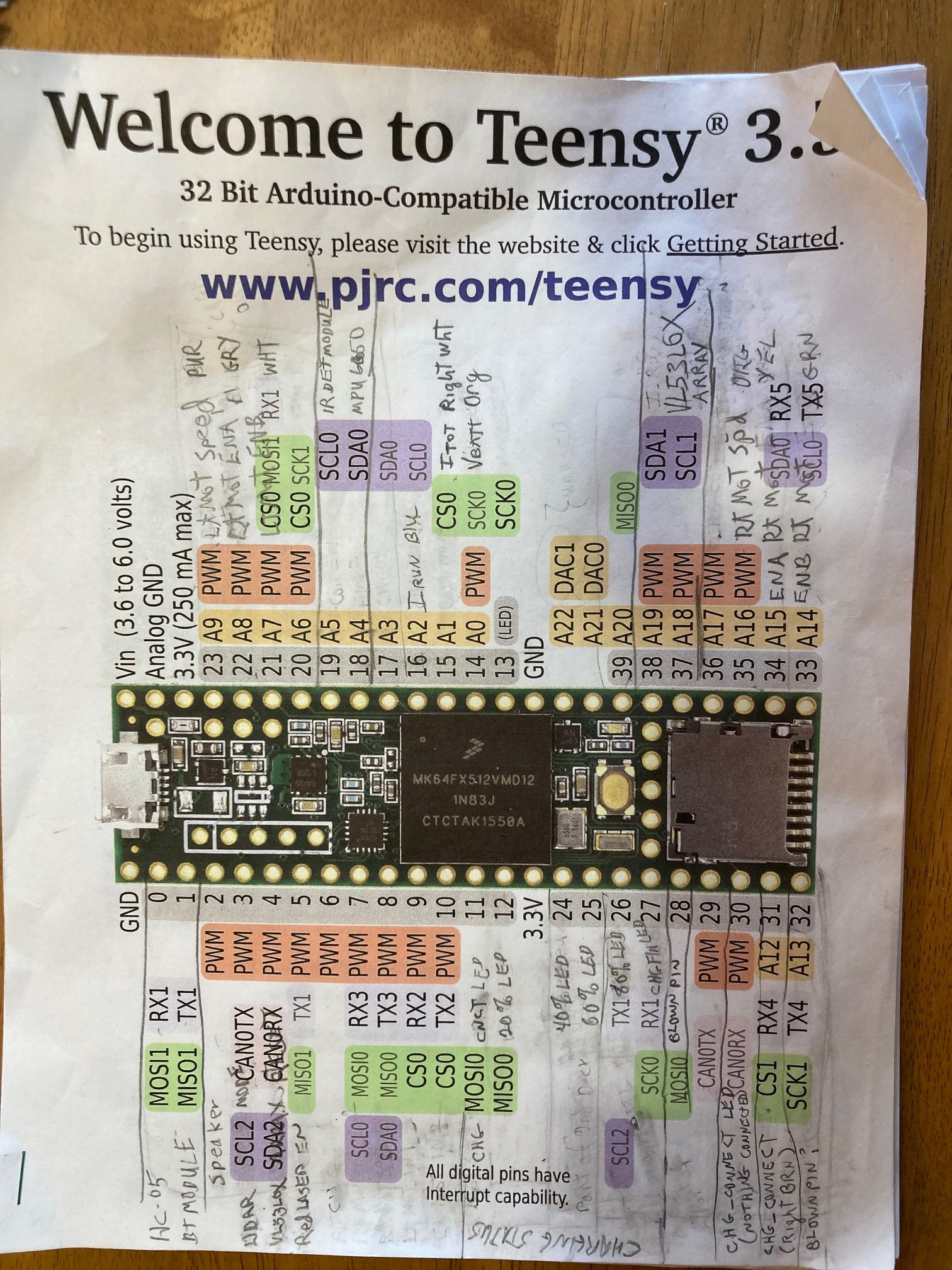
29 November 2021 Update:
Here’s my first cut at a system-level schematic for the new Wall-E3 robot:
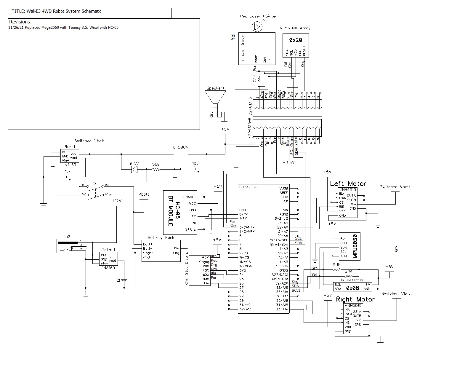
The above schematic has the same basic layout as for Wall-E2, with the following changes:
- The Wixel RF serial extender module has been replaced by the HC-05 Bluetooth module (physically located on the small perf-board module along with the 5V LDO voltage regulator)
- The left and right motor drivers are now VNH5019 parts instead of DRV8871
- The MPU6050 & IR Detector modules now use their own I2C channel (SDA1/SCL1) instead of everything being serviced on the single I2C channel available on the Mega 2560
- The VL53L0X ToF sensor array is still managed by a separate Teensy 3.5, but now is the only device on the primary (SDA0/SCL0) I2C bus
At this point I have verified proper operation for both VNH5019 motor drivers, both 1NA169 inline current sensors, the MPU6050 IMU and the HC-05 Bluetooth module.
The next big milestone is to get the second-deck mounted and verify proper operation of the forward-looking LIDAR and the VL53L0X side and rear ToF distance sensors.
Stay tuned,
Frank