Posted 20 March, 2021
In order to realize my long-term goal of a fully autonomous wall-following robot, Wall-E2 has to be able to reliably mate to its charging station when it gets low on go-juice. Unfortunately, Wall-E2 occasionally fails to mate properly, usually due to an initial misalignment with the center of the IR homing beam. I haven’t worried too much about this, as there have been more pressing problems, but as these have been solved, the mating problem has risen to the top of the to-do list.
The basic geometry for the charging station is shown below:
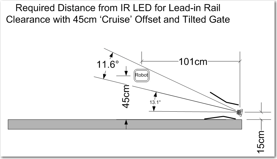
As long as the robot starts its approach on or near the boresight of the IR beam, all goes swimmingly. However, if Wall-E2 detects the IR beam while tracking the wall at right angles to the one depicted above, it can easily start its approach before getting to the center of the beam, resulting in it getting stuck on the outside guide-in rail (upper rail in the above diagram). In addition, if Wall-E2 is tracking too close to the wall above, it can actually get stuck on the inside guide-in rail (lower rail in the above diagram).
So, what is needed here is a way to force the robot to line up on the IR beam centerline before committing to the mating approach. To investigate this, I created a part-task version of Wall-E2’s operating system that does just one thing; it detects the IR homing signal, and then takes action to position itself in the center of the IR homing beam, aligned with the beam’s boresight. In the aviation instrument (blind) flying world, this is known as the ‘IAP’ (Initial Approach Point), so I needed to create an algorithm so Wall-E2 could navigate to the Charging Station IAP, and start it’s final approach from the same place every time.
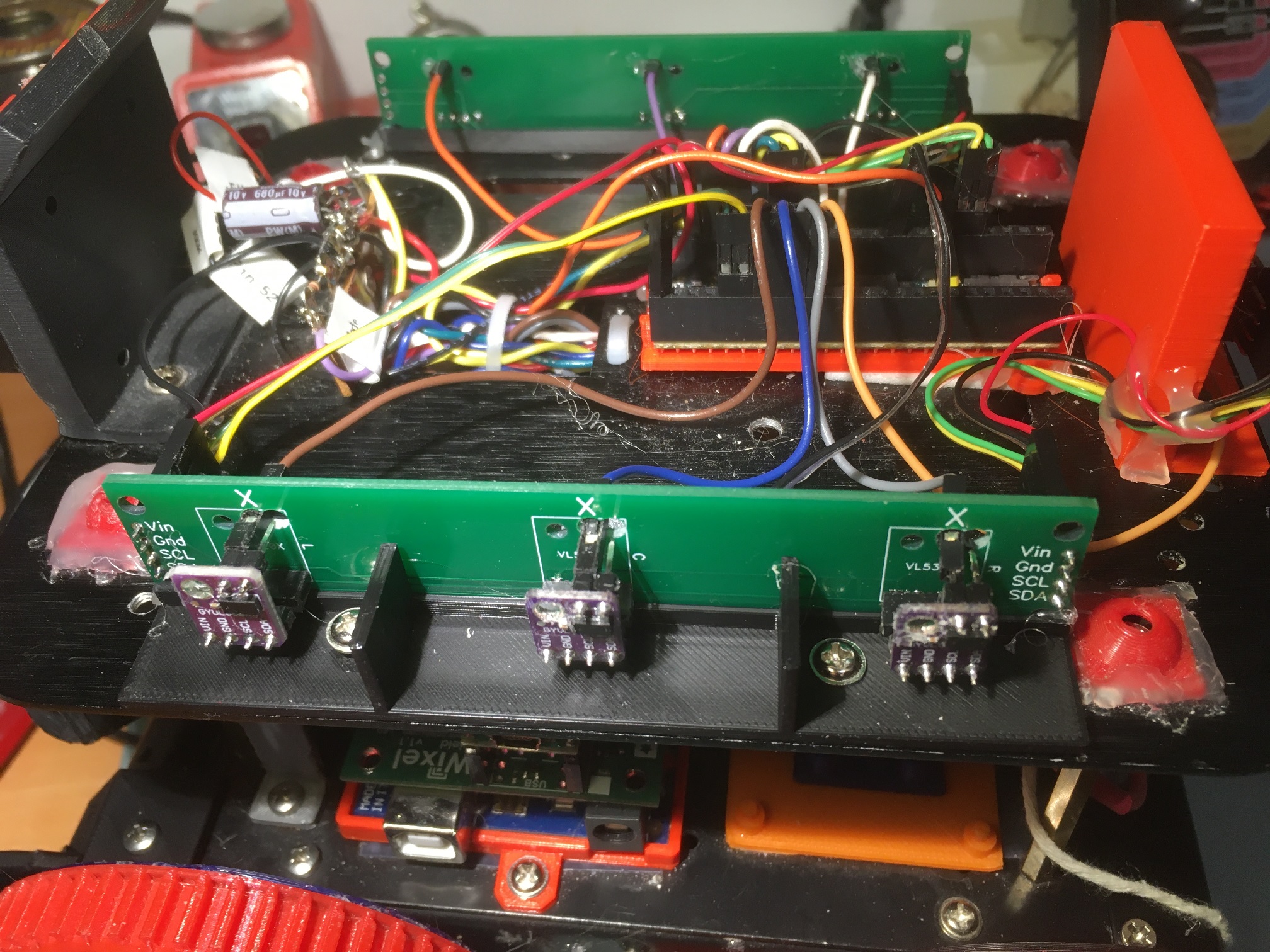
In previous work I have gotten Wall-E2 smart enough to track walls at a constant offset. so this is where I started with the current effort. When Wall-E2 starts to track a wall, the first thing it does is use the near-side array of VL53L0X IR laser TOF sensors to orient parallel to the wall, without regard to the absolute offset. It then angles toward or away from the wall to achieve tracking at the desired offset.
The starting position for the current effort is with the robot placed close to the wall leading to the charging station, pointed generally toward the charging station. When the robot wakes up, it sees that there is an active IR homing beacon, and takes action to navigate to the IAP.
- First it uses the parallel orientation algorithm to align itself parallel to the near wall so it can measure it’s offset from the wall, and also to ensure that the front distance measurement accurately reflects the distance from the robot to the charging station.
- Next, it compares the wall offset and front distance measurements to the known values for the IAP, i.e. a 50 cm offset at a distance of 180 cm. It then calculates how much additional offset it needs to place itself in the center of the beam.
- If necessary, the robot turns 90º away from the wall and moves away to achieve the desired offset. If the robot is already far enough away from the wall, it skips this step
- After getting far enough away, the robot turns in place (a ‘Spin Turn’) until the signal strength of the received IR homing beacon rises above a set threshold. This gets the robot oriented generally in the direction of the charging station
- The last step is to fine-tune the robot’s orientation so that it is centered in the beam and also well aligned with the beam boresight.
The following photograph shows the robot at the IAP, ready to start the final approach to the charging station.
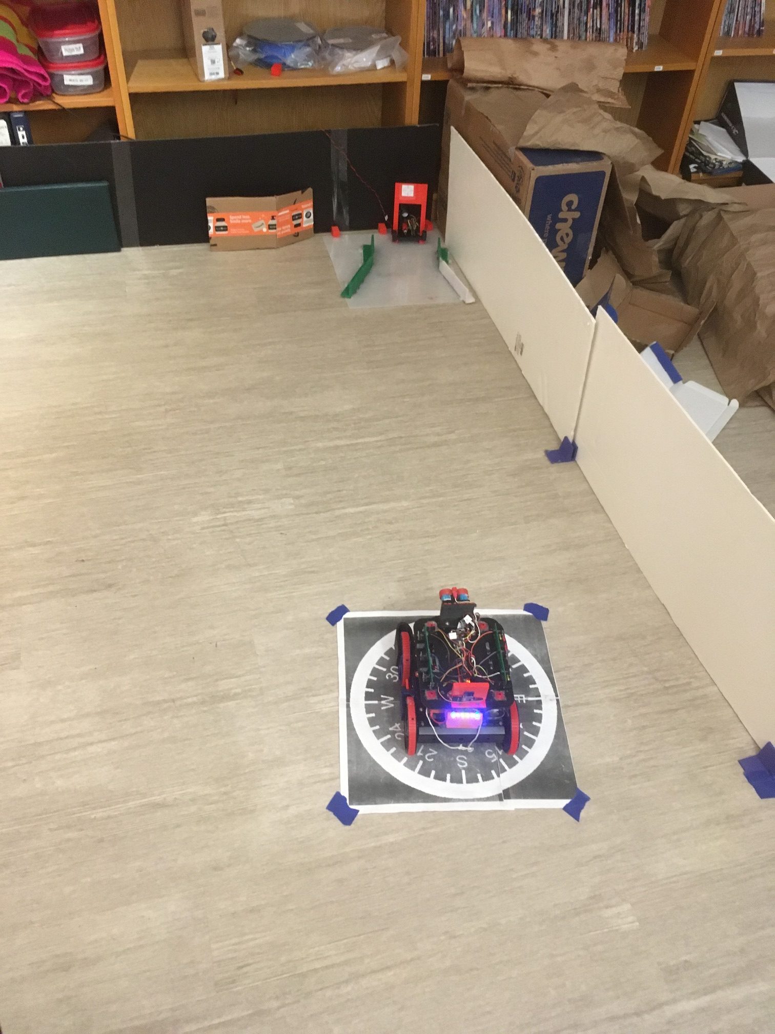
And the following video shows the entire process, up to the point where the robot would actually start the final approach.
15 April 2021 Update:
One of the issues with the current initial approach algorithm is the lack of accuracy in achieving the desired wall offset, due to Wall-E2’s tendency to ‘coast’ past the desired distance. I could just lower the offset target by a fixed amount to account for the ‘coast’ effect, but since that changes significantly depending on whether Wall-E2 is on carpet or hard flooring, that doesn’t sound like a good ide.
Instead, I decided to use yet another PID object to manage offset distance acquisition, using the following algorithm:
|
1 2 3 4 5 6 7 8 9 10 11 12 13 14 15 16 17 18 19 20 21 22 23 24 25 26 27 28 29 30 31 32 33 34 35 36 37 38 39 40 41 42 43 44 |
//04/12/21 Wall offset testing const double OffsetDistKp = 5.f; const double OffsetDistKi = 3.f; const double OffsetDistKd = 0.0f; double OffsetDistSetpointCm, OffsetDistOutput;//10/06/17 chg input variable name to something more descriptive volatile double OffsetDistVal = 0; //11/07/20 needs to be volatile as it is updated in ISR (and has to be 'double') PID OffsetDistPID(&OffsetDistVal, &OffsetDistOutput, &OffsetDistSetpointCm, OffsetDistKp, OffsetDistKi, OffsetDistKd, DIRECT);//12/14/20 re-doing this from scratch OffsetDistPID.SetMode(AUTOMATIC); OffsetDistPID.SetSampleTime(0); OffsetDistPID.SetOutputLimits(-MOTOR_SPEED_HALF, MOTOR_SPEED_HALF); StopBothMotors(); int speed; OffsetDistSetpointCm = 30; mySerial.printf("Msec\tDist\tdiff\tspeed\tvar\tavg\n"); uint16_t avg = CalcRearDistAvgMM(Lidar_Rear, Rear_Dist_PrevMean); while (abs(Lidar_Rear - 10*OffsetDistSetpointCm) > 10 || abs(avg - 10*OffsetDistSetpointCm) > 10) { CheckForUserInput(); if (bTimeForNavUpdate) { bTimeForNavUpdate = false; OffsetDistVal = Lidar_Rear / 10; OffsetDistPID.Compute(); speed = (int)OffsetDistOutput; uint16_t rear_var = CalcRearDistArrayVariance((unsigned long)Lidar_Rear); avg = CalcRearDistAvgMM(Lidar_Rear, Rear_Dist_PrevMean); mySerial.printf("%lu\t%2.2f\t%2.2f\t%d\t%d\t%d\n", millis(), OffsetDistVal, OffsetDistOutput, speed, rear_var, avg); if (speed >= 0) { RunBothMotors(true, speed, speed); } else { RunBothMotors(false, -speed, -speed); } } } mySerial.printf("Stopped at %2.2f cm with avg = %d\n", (float)Lidar_Rear / 10, avg); StopBothMotors(); |
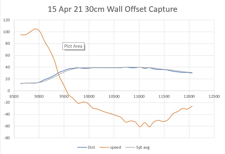
Using this code, I got the following output:
And a short video showing the offset acquisition process:
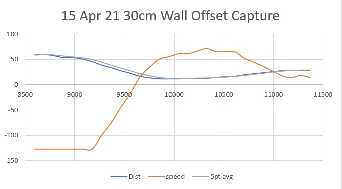
Here’s the same process, but starting from farther away than desired
21 April 21 Update:
After some additional work on the initial approach algorithm, I arrived at a pretty nice spot; Wall-E2 will reliably detect the IR homing beacon, offset the proper amount from the wall using a 90º turn and a PID engine-driven rear-distance controlled movement, and then rotate to orient to the IR beam boresight. The ‘rotate-to-boresight’ operation takes place in two stages. In the first stage, the robot turns toward the beacon in 10deg steps until the beacon is re-acquired (this is necessary because the robot loses the beam signal when it turns 90º to the wall) and then uses another PID-driven algorithm to center up on the beam boresight. Here’s a short video showing the process.
As can be seen from the above video, the robot successfully navigates to the initial approach point (IAP), rotates to orient with the homing beacon boresight, and then homes to the charging station. This all works, but it is pretty clunky and inelegant. The initial 90º turn away from the wall is in itself a bit problematic, as it can easily overshoot, and then the robot loses the beacon signal, which means that after the appropriate wall offset has been reached, the robot has to turn back toward the charging station to re-acquire the signal, and it has to do so ‘gently’ so as not to overshoot.
I think it would be much better if the initial turn away from the wall was just 45º so the robot won’t lose the beacon signal while navigating to the IAP, and potentially eliminating the first part of the ‘rotate to boresight’ phase. Here is the relevant geometry:
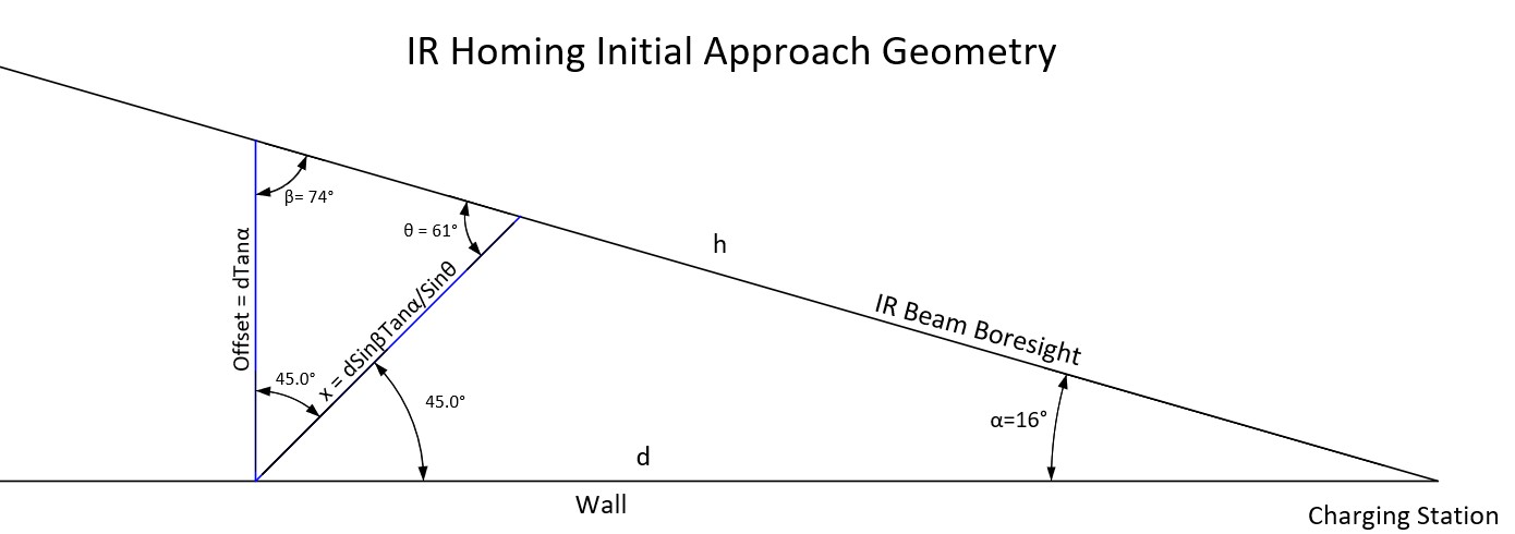
In the above figure, the robot currently makes a 90º utilizes the line labelled ‘Offset =…’ to offset out to the IR beam boresight. I’m thinking that the line labelled ‘x = …’ would work better, as the robot only has to make a 45º turn initially, and then the robot might not lose the beam signal as it offsets out to the IR boresight line. Here’s the supporting math.
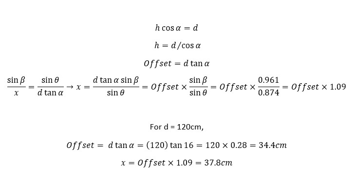
In the above figure, an example is worked out for d = 120cm, where the perpendicular offset is found to be 34.4cm and the 45º turn distance is found to be 1.09*Offset = 37.8cm.
23 April 2021 Update:
The change from 90º to 45º IAP approach angle turned out to be pretty easy to do – really just a matter of changing ‘SpinTurn(90)’ ‘SpinTurn(45)’ and the offset value to 1.09 x offset. Here’s a short video showing the result.
After a few more runs (with some failures due to the robot hanging up on the outside rail), I realized my basic beam geometry estimate was significantly off. Instead of a beam angle of about 16deg, it was more like 11, yielding a distance::offset ratio of about 0.18 instead of 0.27. Revising the program to use the more accurate ratio resulted in the following much nicer homing run.
And here is the telemetry from the run:
|
1 2 3 4 5 6 7 8 9 10 11 12 13 14 15 16 17 18 19 20 21 22 23 24 25 26 27 28 29 30 31 32 33 34 35 36 37 38 39 40 41 42 43 44 45 46 47 48 49 50 51 52 53 54 55 56 57 58 59 60 61 62 63 64 65 66 67 68 69 70 71 72 73 74 75 76 77 78 79 80 81 82 83 84 85 86 87 88 89 90 91 92 93 94 95 96 97 98 99 100 101 102 103 104 105 106 |
In RotateToParallelOrientation(Right) ToFArrayPID Parameters (Kp,Ki,Kd,DIR) = (200.00,180.00,240.00,0) ToFArrayPID output max/min = 127/-127 Time Fdist Cdist Rdist Fdist Steer Cur*Pr PIDout Lspd RSpd 8785 258 252 286 116 -0.28 0.07 127.00 0 254 8881 260 256 281 128 -0.21 0.06 -114.82 241 12 8979 255 251 276 158 -0.21 0.04 57.14 69 184 9073 255 245 282 151 -0.27 0.06 127.00 0 254 9169 255 245 282 211 -0.27 0.07 79.22 47 206 9268 242 228 259 218 -0.17 0.05 -127.00 254 0 9361 230 202 231 215 -0.17 0.03 65.70 61 192 Parallel Orientation Achieved at 9364 with SteeringVal = -0.01 & bIRBeamAvail = TRUE OK we have a IR Beacon, with front distance = 215! In IRHomingNavigateToIAP with LF/LR/LS/RF/RR/RS = 8190 679 75.11 243 232 0.11 IP is at 32 cm offset, 180cm away from charging station, a ratio of 0.18 Robot is at 196 from charger, so we need a 35 cm offset Current wall offset (cm) is 21.40 or 61% of required offset offset is too small or too large - turn away from wall to adjust After SpinTurn(), rear dist (cm) is 33 Msec Dist diff speed var avg 10999 26.00 47.70 47 27841 491 11097 22.00 71.60 71 7108 261 11194 22.00 75.50 75 5802 234 ... 13015 39.00 -8.60 -8 5622 396 13112 39.00 -9.80 -9 5621 396 13207 40.00 -16.30 -16 5632 399 13305 39.00 -12.50 -12 5642 397 13402 39.00 -13.70 -13 5642 396 13497 40.00 -20.20 -20 5632 397 13591 40.00 -21.70 -21 5622 400 13685 39.00 -17.90 -17 5622 399 ... 15313 38.00 -33.90 -33 5631 390 15411 39.00 -40.10 -40 5631 391 15506 38.00 -36.00 -36 5632 391 15602 38.00 -36.90 -36 5629 390 15697 39.00 -43.10 -43 5632 392 15794 38.00 -39.00 -39 5635 391 15889 40.00 -50.50 -50 5644 394 15985 40.00 -52.00 -52 5653 398 16078 39.00 -48.20 -48 5628 398 16180 39.00 -49.40 -49 5630 396 16276 38.00 -45.30 -45 5626 392 16371 38.00 -46.20 -46 5626 389 16468 37.00 -41.80 -41 5670 381 16564 36.00 -37.10 -37 5681 372 16659 36.00 -37.40 -37 5633 365 16757 35.00 -32.40 -32 5642 359 Stopped at 35.40 cm with avg = 359 Wall offset (cm) now 35, with IRHomingValTotalAvg = 24714 Now rotating to achieve avg value > 15000 Msec ValAvg TurnToHomingBeacon with Steering = 0.99 & IRRotate Kp,Ki,Kd = (75,68,90) TurnToHomingBeacon(RIGHT) Msec Signal Steer Val 16855 25031 0.99 77.42 16950 25309 0.99 85.94 17049 25742 0.98 87.80 17143 26667 0.97 93.47 17241 28398 0.94 70.95 17339 30002 0.90 68.24 17436 31002 0.88 94.82 17532 31554 0.84 83.08 17629 32456 0.81 88.08 17723 34123 0.75 66.22 17821 36159 0.66 32.28 17920 37863 0.55 7.43 18015 38913 0.51 79.82 18110 39181 0.51 115.91 18204 39323 0.50 104.22 18301 39952 0.36 -13.31 18400 41434 0.11 -127.00 18494 42963 0.04 22.60 TurnToHomingBeacon exited with Steering = 0.04 Should be close to beacon centerline val avg = 42963, SteeringVal = 0.041 IRHomeToChgStn with detection value = 42963, Steering = 0.04 & IRHOMING Kp,Ki,Kd = (100,90,120) front dist = 192, lastHomingTelemetryMsec = 12 Time BattV Fin1 Fin2 Steer PID_Out LSpd RSpd FrontD RearD 18785 7.71 25482 17878 0.18 -118.68 8 245 186 1186 18976 7.70 14622 31040 -0.36 -127.00 0 254 164 1020 19171 7.69 30166 21000 0.18 127.00 254 0 174 8190 19360 7.77 31456 26846 0.08 -127.00 0 254 156 8190 19552 7.75 26844 39502 -0.19 -27.31 99 154 144 8190 19748 7.75 44104 36840 0.09 127.00 254 0 140 8190 19941 7.73 39250 54988 -0.17 -127.00 0 254 129 8190 20137 7.71 54326 60540 -0.05 127.00 254 0 115 8190 20331 7.75 74378 66494 0.06 -36.61 90 163 99 8190 20525 7.74 72640 101500 -0.17 -92.89 34 219 85 8190 20719 7.70 127128 101718 0.11 127.00 254 0 82 8190 20914 7.85 150490 157470 -0.02 -127.00 0 254 70 8190 21106 7.78 204068 227704 -0.05 64.30 191 62 66 8190 21401 7.74 430668 395454 0.04 -127.00 0 254 36 8191 21597 7.74 687992 776442 -0.06 43.76 170 83 23 8191 21795 7.74 1570870 1145658 0.16 53.77 180 73 15 8191 Accelerating to Contact with frontdist = 15 Accelerating to Contact with frontdist = 4 21993 7.75 2447090 2476002 -0.01 -7.92 119 134 5 -1 Accelerating to Contact with frontdist = 5 Accelerating to Contact with frontdist = 3 22194 7.60 2469022 2490074 -0.00 2.01 129 124 4 -1 Accelerating to Contact with frontdist = 4 Accelerating to Contact with frontdist = 4 22394 7.72 2461754 2490566 -0.01 -0.65 126 127 5 -1 Accelerating to Contact with frontdist = 5 Charger Connected at 22398 |
Much nicer!
Stay tuned!
Frank