Posted 31 May 2024
The folks at TrueTheVote.org (the organization that used cellphone geotracking to expose widespread voter fraud during the 2020 election) put together a database to expose huge numbers of invalid voter registrations across the country. Most of these invalid registrations are due to the voter having moved out of their original voting district/county, but not removed by the responsible election board. While this seems pretty innocuous (and was, in earlier, less troubled times), this now represents a huge opportunity for fraud in the upcoming 2024 election.
Although the TTV folks have the data, they can’t do much about it without the help of concerned citizens who actually vote in those regions because local laws require that any voter challenge be raised by a voting citizen in that particular region.
So, TTV generated a website called ‘IV3’ which allows concerned citizens from anywhere in the U.S. to create an account and query the IV3 database for problematic voter registration records for their voting district/county. For instance, I live and vote in Franklin county, Ohio and my page on the IV3 site looks like this:
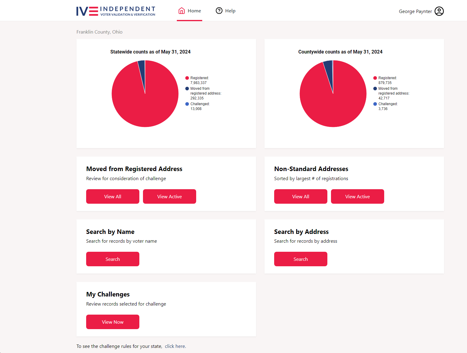
If I click on ‘View Active’, I get a page displaying the first record that matches the criteria, i.e. a voter still registered in Franklin county but who has since moved to an address outside of the County, as shown below:
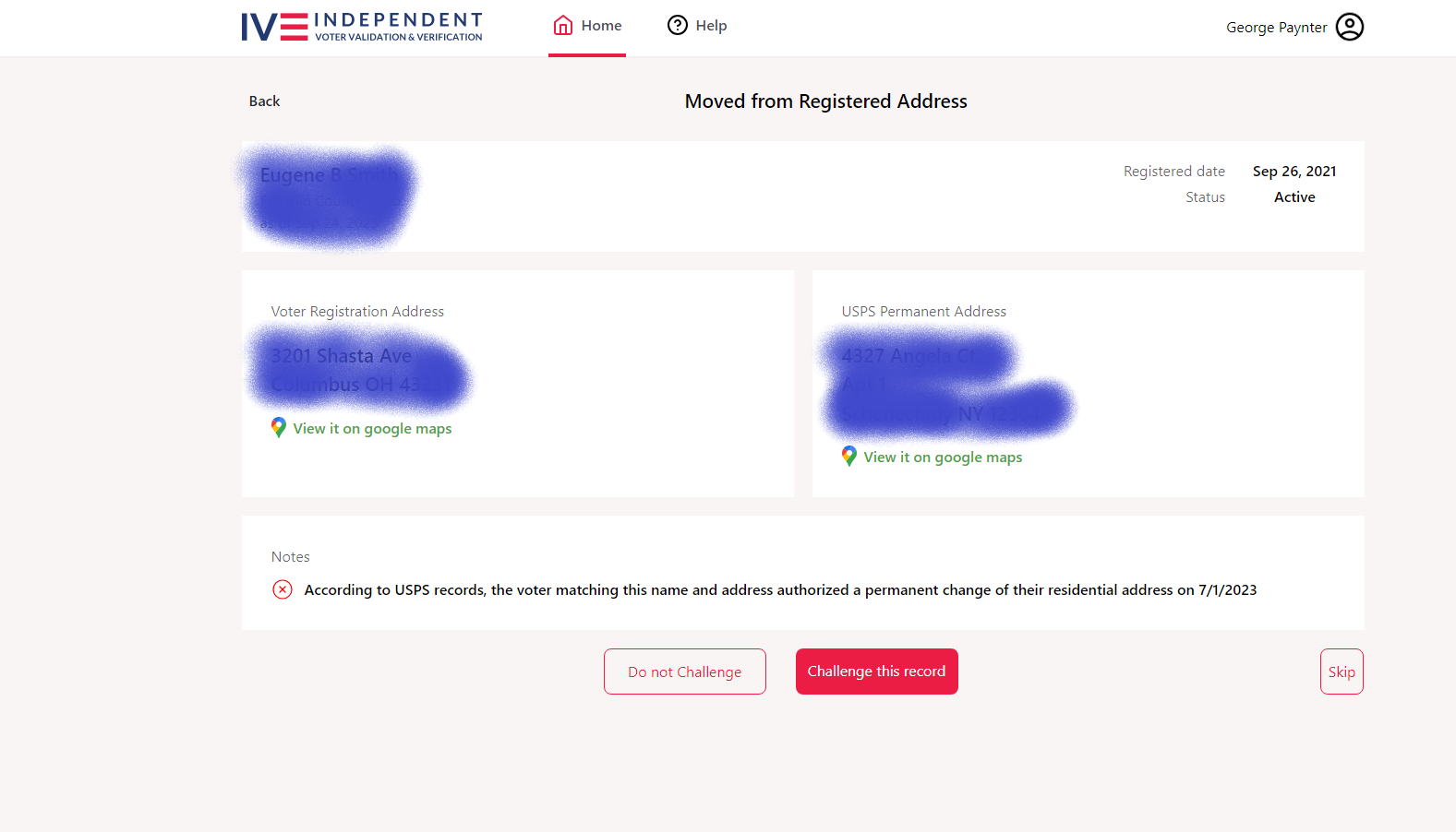
If I want to challenge this voter’s registration in Franklin county, I would click on ‘Challenge this record’, which would display ‘Cancel’ and ‘Submit’ buttons as shown below:
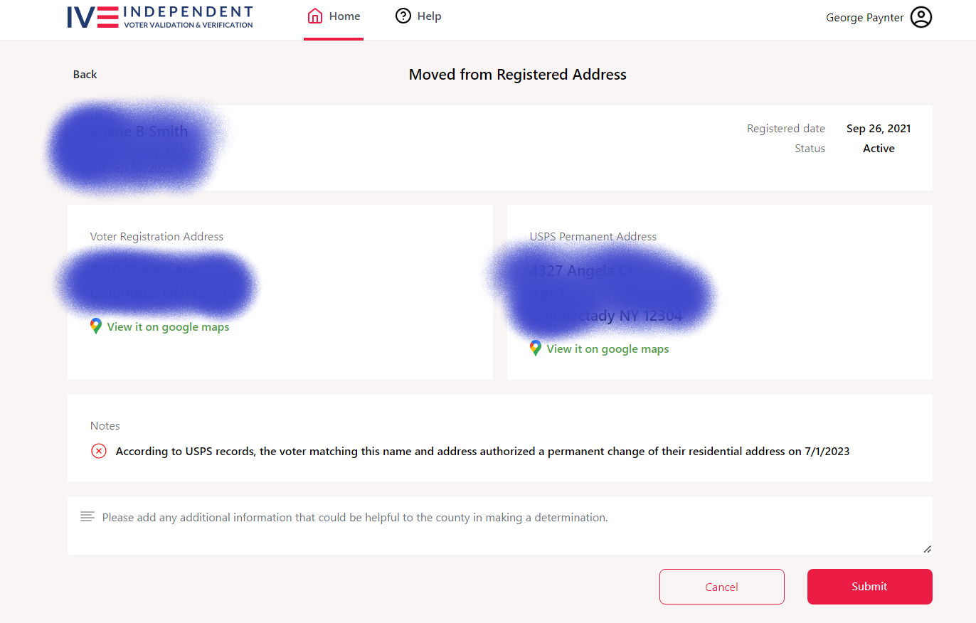
Clicking on the ‘Submit’ button would remove the record from the ‘Active’ list and place it on the ‘Challenged’ list, which could then be exported in .CSV format for submission to the Franklin county board of elections.
It sometimes takes more than 100 seconds for the site to display a new record after each challenge submission, so this gets old pretty fast. After several days of plugging along while working on other things, I had managed to challenge about 600 records from the more than 42,000, a mere ‘drop in the bucket’. So, I started to wonder if I might be able to automate this a bit with a Python script; a web-bot of sorts.
After some research, I discovered a web-page automation API called ‘Selenium’ that could be called from a Python script, so I started learning how to use Selenium to do what I wanted. After the usual number of mistakes and appeals to StackOverflow for guidance, I got a working Python script together, as shown below:
Note that in order to use this script, you must have Python3 and the Selenium extension installed on your computer.
|
1 2 3 4 5 6 7 8 9 10 11 12 13 14 15 16 17 18 19 20 21 22 23 24 25 26 27 28 29 30 31 32 33 34 35 36 37 38 39 40 41 42 43 44 45 46 47 48 49 50 51 52 53 54 55 56 57 58 59 60 61 62 63 64 65 66 67 68 69 70 71 72 73 74 75 76 77 78 79 80 81 82 83 |
from ast import Num from re import L from selenium import webdriver from selenium.webdriver.chrome.webdriver import WebDriver from selenium.webdriver.common.keys import Keys from selenium.webdriver.common.by import By from selenium.webdriver.support.wait import WebDriverWait from selenium.webdriver.support import expected_conditions import time import sys import os #notes: # 6/22/2024 added some code to print out the full path to the script for troubleshooting purposes # 6/22/2024 changed the script target from the 'Active View' button to the 'View Moved and Registered' button curdir = os.getcwd() print('My current directory is {}'.format(curdir)) filename = 'IV3_WebsiteAutomation.py' fullpath_to_filename = os.path.join(curdir, filename) print('When I run `open(filename)`, python sees: {}'.format(fullpath_to_filename)) print('This filepath is {}valid'.format('' if os.path.exists(fullpath_to_filename) else 'not ')) def FranklinCountyOhioChallenges(number_of_names): print(f'Preparing {number_of_names} Franklin County Challenges') cService = webdriver.ChromeService(executable_path="C:\\Users\\Frank\\Documents\\Visual Studio 2022\\Projects\\IV3_WebsiteAutomation\\chromedriver.exe") #05/27/24 suppress errors options = webdriver.ChromeOptions() options.add_experimental_option('excludeSwitches', ['enable-logging']) driver = webdriver.Chrome( service= cService, options=options, ) driver = webdriver.Chrome(service = cService) driver.get("https://app.iv3.us/login") print(driver.title) driver.implicitly_wait(5) search_bar = driver.find_element("name", "userName") search_bar.send_keys("paynterf@gmail.com") search_bar = driver.find_element("name", "password") search_bar.send_keys("hbMjMCx%f7Zb-eno") search_bar.send_keys(Keys.RETURN) wait = WebDriverWait(driver, timeout=300) #06/22/24 Data was moved to another button # active_btn = driver.find_element(By.XPATH,"/html//div[@id='app-container']/div[@class='h-full']//a[@href='/assignedVoters?activeOnly=true']") active_btn = driver.find_element(By.XPATH,"/html//div[@id='app-container']/div[@class='h-full']//a[@href='/assignedVoters?movedAndRegistered=true']") wait.until(lambda d : active_btn.is_displayed()) active_btn.click() #At this point we should be on the page containing the information for a Franklin-county registered voter whose current address #isn't within the boundaries of Franklin county. So, we want to click the 'challenge this voter' button, then the 'submit' button #and then wait until a new record is displayed, which could take ten seconds or more. tot_secs = 0 ts_start = time.time() print("start time = ", ts_start) for x in range(1,number_of_names): wait.until(expected_conditions.element_to_be_clickable((By.XPATH,"/html//div[@id='app-container']//button[.='Challenge this record']"))).click() wait.until(expected_conditions.element_to_be_clickable((By.XPATH,"/html//div[@id='app-container']//button[.='Submit']"))).click() ts_index = time.time() num_secs = ts_index - ts_start tot_secs += num_secs print(f'index = {x}, duration = {num_secs}') ts_start = ts_index else: num_minutes = tot_secs/60 print(f'All Done. Did {number_of_names} records in {num_minutes} minutes') driver.close() if __name__ == '__main__': FranklinCountyOhioChallenges(int(sys.argv[1])) |
Even though I used ‘FranklinCountyOhioChallenges’ as the name of the main function, this script should be usable for any other location (or you can simply change the name, as long as the two occurrences in the script have identical names).
After getting the script working, I can now run the script to challenge any number of voters with a very simple command, as shown below:
|
1 2 3 4 5 6 7 8 9 10 11 12 13 14 15 16 17 |
C:\Users\Frank\Documents\Visual Studio 2022\Projects\IV3_WebsiteAutomation>python IV3_WebsiteAutomation.py 10 Preparing 10 Franklin County Challenges DevTools listening on ws://127.0.0.1:58881/devtools/browser/bef94364-45bd-4df9-9fb9-d71e103383bf IV3 start time = 1717013181.6964138 Created TensorFlow Lite XNNPACK delegate for CPU. index = 1, duration = 12.476682662963867 index = 2, duration = 96.29976963996887 index = 3, duration = 26.91017436981201 index = 4, duration = 34.119770765304565 index = 5, duration = 23.901393175125122 index = 6, duration = 103.53411984443665 index = 7, duration = 108.87294125556946 index = 8, duration = 43.939680099487305 index = 9, duration = 4.500910520553589 All Done. Did 10 records in 7.575924038887024 |
On my windows system (and I’m pretty sure this holds for **nux systems as well) all I have to do to run another batch of the same size is to click on the ‘up-arrow’ button once and then hit ‘Return’. If a different batch size is desired, it’s ‘up-arrow’, edit the batch size, then ‘Return’.
I have found that doing a batch size of 100 takes about 90 minutes, so I can do several of these during the day while working on other things, and then I generally do a batch of 500 overnight. This allows me to do at least 1000 or so each day, so it will still take me around 42 days to challenge all the 42K or so registered voters who have moved out of the county. Your mileage may vary, of course :).
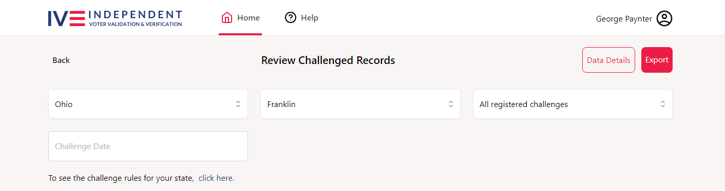
Each time I get a thousand or so challenges done, I click on the ‘View My Challenges’ button on the main page, and then on the ‘Export’ button as shown below, to download the challenges into a .CSV file that is directly readable in Excel (or any other modern spreadsheet program). I then use Excel to print out the entire batch (using Portrait mode and scaling to ‘fit all columns on one page’). Then I fill out and sign the cover form required by the Franklin County Board of Elections, attach the printed out challenge records, and physically submit the form and data to the BOE. As courtesy I also email the .CSV file to the responsible officer there, and so far they seem to appreciate the effort.
22 June 2024 Update:
My script started failing on me a few days ago, and I couldn’t see why. After using the issue as my ‘going to sleep puzzle’, I realized I could go back to my old manual process and see if it worked. If it did, then something in my script was bad. If it failed, then something had changed on the iv3 website.
As it turned out, IV3 had added a new ‘View Moved and Registered’ button, and moved all the qualifying records (which, it turned out, was all of them) into the new database. So, when I clicked on my normal ‘View Active’ button, I got ‘No Records Found’, which of course also killed my script :(.
So, the fix was to direct my script to the new button instead, and then all was well. I have updated the above script to the new version.
Stay tuned,
Frank