Posted 12/23/22
In the last couple of months I have made some significant improvements in WallE3’s capabilities. I started by completely re-doing the compensation algorithms for the seven ST Micro’s VL53L0X time-of-flight distance sensors (two each 3-element side-looking arrays and one rear-looking distance sensor). I followed this with improvements to both the ‘spin turn’ and ‘rolling turn’ features.
Next, I went back through my ‘MoveToDesiredLeft/Right/Front/RearDistCm()’ family of subroutines and made sure they were all working properly now with the much more accurate distance compensation algorithms. One interesting thing that came out of this effort was the realization that shorter measurement intervals (i.e. 50mSec vs 200mSec) produced an unintended side-effect of making ‘Stuck’ detections much more prevalent. This occurs because the appropriate (front or rear) 50-element distance array fills up much faster at 50mSec/measurement than it does at 200mSec/measurement, so identical (or nearly identical measurements will cause a stuck detection earlier (5 measurements/sec means a 50 element array will fill in 10 sec but 20meas/sec fills the array in 2.5sec. When I used 50mSec/meas in the ‘MoveToDesired…()’ routines, the robot would often exit the routine with a ‘stuck’ error code as it slowed down approaching the desired distance condition. These functions do fine with a more coarse time interval (eliminating the ‘stuck’ declarations), so I went back to 200mSec/measurement.
Now I am going to try to incorporate the above improvements into my previous wall track testing program, ‘WallE3_WallTrackTuning_V4’. As usual, I will start by creating ‘WallE3_WallTrackTuning_V5’ as a clone of ‘_V4’ and start making changes from there.
WallE3_WallTrackTuning_V5:
I am going to try and make WallE3_WallTrackTuning_V5 as ‘clean’ as possible, removing as much ‘dead’ code as possible and consolidating things like sensor measurement intervals.
Timing intervals:
Searching through the code for ‘elapsedMillis’ objects, I see the following global declarations:
|
1 2 3 4 |
elapsedMillis MsecSinceLastTurnRateUpdate;//heading/rate based turn support elapsedMillis mSecSinceLastWallTrackUpdate; elapsedMillis MsecSinceLastDistUpdate; //01/07/22 used for local dist update loops elapsedMillis MsecSinceLastFrontDistUpdate; //10/02/22 slower update rate needed for front LIDAR |
Then I did a search for “MSEC” all upper case and found:
|
1 2 3 4 5 6 7 8 |
//in 'Distance Measurement Support const uint16_t MSEC_PER_DIST_UPDATE = 200; //12/10/22 can't go any faster than 200mSec - due to longer meas budg for VL53L0X accuracy //In 'Wall Follow Support' const uint16_t TURN_RATE_UPDATE_INTERVAL_MSEC = 30; //30 mSec is as fast as it can go reliably const uint16_t WALL_TRACK_UPDATE_INTERVAL_MSEC = 200; const uint16_t FRONT_DISTANCE_UPDATE_INTERVAL_MSEC = 250; //10/02/22 added to separate out slow front LIDAR from faster VL53L0X sensors const uint16_t ROTATE_TO_PARALLEL_TELEMETRY_SPACING_MSEC = 200; |
The front LIDAR sensor starts to generate errors for long distance measurements when the measurement interval falls below 200mSec
The VL53L0X time-of-flight sensors need a ‘measurement time’ of 50mSec or greater. This is handled by the VL53L0X array Teensy, but it means that UpdateAllEnvironmentParameters() shouldn’t be called more frequently than 20HZ.
The MPU6050 can support an update interval of 30mSec or greater, and this time is used for all turning operations.
Telemetry readouts should occur no more than once every 200mSec.
MoveToDesiredFront/Back/Left/RightDistCm()
Based on my recent work on these functions, it looks like PID = (1.5, 0.1, 0.2) will work for all cases, so all I have to do is modify the existing ‘OffsetDistKp/Ki/Kd’ values. Note that in my testing these were parameters to the function call instead of program constants, but now I can go back to just having the desired offset as the only parameter.
So, I copied each of the above functions to WallE3_WallTrackTuning_V5 from WallE3_FrontBackMotionTuning_V1, removed Kp,Ki,Kd from the sig, and replaced all occurrences with OffsetDistKp/Ki/Kd. I also ported the CorrDistForOrient() function, as it is required by the MoveToDesiredLeft/Right() versions
01 January 2023 Update:
After getting the ‘MoveTo…’ functions working, I discovered that ‘RotateToParallelOrientation()’ didn’t work well at all, and in fact found a note from my former self that the function was ‘fatally flawed’ – oops! So, I revisited my ‘WallE3_ParallelFind_V1’ part-task project to see if I could get it to work better now that VL53L0X distances are being reported as float vs integer objects, and after what I hope is much better sensor error compensation. As shown in this post, RotateToParallelOrientation() now works much better, albeit somewhat slowly, with PID = (20,4,0).
|
1 2 3 4 5 6 7 8 9 10 11 12 13 14 15 16 17 18 19 20 21 22 23 24 25 26 27 28 29 30 31 32 33 34 35 36 37 38 39 40 41 42 43 44 45 46 47 48 49 50 |
Tracking Left Wall with offset = 50 and PID = (10.0,0.0,0.0) Enter 's' key to start Msec LF LC LR Steer In CaptureWallOffset(Left, 50.0) R/C/F dists = 16.6 14.2 15.3 Steerval = -0.130, WallAngle = -7.43, Inside In CaptureWallOffset():turndeg = -37.4 Just before call to MoveToDesiredLeftDistCm(50.0); In MoveToDesiredLeftDistCm(50) with Kp/Ki/Kd = 1.5/0.1/0.2 MTLD: at start, tgt = 50cm, corr_dist = 13.9, tgt_window = 2.0, front/rear var = 12985.0/790.4 Msec Left Steer LCorr TgtD err Ival Dval Out Speed FVar RVar 44703 20.4 0.6 12.6 50 37.4 3.7 37.4 52.3 52 12702.1 754.1 44903 22.1 0.5 14.3 50 35.7 7.3 -1.7 61.1 61 12477.4 722.9 45103 25.7 0.6 15.9 50 34.1 10.7 -1.6 62.1 62 12309.2 687.0 45303 33.3 0.5 23.8 50 26.2 13.3 -7.9 54.2 54 12195.2 652.3 45503 40.9 0.5 28.5 50 21.5 15.5 -4.7 48.7 48 12133.4 616.8 45703 49.9 0.5 33.3 50 16.7 17.1 -4.8 43.1 43 12121.4 583.1 45903 54.3 0.4 44.4 50 5.6 17.7 -11.1 28.3 28 12156.6 555.0 46103 63.5 0.7 31.5 50 18.5 19.6 12.8 44.7 44 12236.3 527.4 46303 67.3 0.7 35.9 50 14.1 21.0 -4.4 42.9 42 12357.8 501.8 46503 79.8 0.3 65.9 50 -15.9 19.4 -30.0 1.5 1 12518.0 489.6 46703 79.8 0.2 72.2 50 -22.2 17.1 -6.3 -15.0 -14 12713.8 474.1 46903 80.6 0.3 66.6 50 -16.6 15.5 5.7 -10.5 -10 12941.9 470.6 47103 81.6 0.6 50.6 50 -0.6 15.4 16.0 11.4 11 13198.9 456.7 MTLD: Stopped with left dist = 50.6 and errcode = NO_ANOMALIES In RotateToParallelOrientation(Left) with Kp/Ki/Kd = 20.0/4.0/0.0 Msec Hdg FrontD RearD Steer PSteer err Ival Out speed 48315 103.8 70.3 66.2 0.4 0.0 -0.4 -1.6 -9.8 -9 48515 103.8 74.5 68.7 0.6 0.4 -0.6 -4.0 -15.6 -15 48715 103.8 72.2 68.5 0.4 0.6 -0.4 -5.4 -12.8 -12 48915 103.8 74.1 67.4 0.7 0.4 -0.7 -8.1 -21.5 -21 49115 103.8 69.9 67.5 0.2 0.7 -0.2 -9.1 -13.9 -13 49315 103.8 68.7 65.1 0.4 0.2 -0.4 -10.5 -17.7 -17 49515 103.8 70.5 65.9 0.5 0.4 -0.5 -12.4 -21.6 -21 49715 103.8 70.2 66.3 0.4 0.5 -0.4 -13.9 -21.7 -21 49915 103.8 70.3 65.0 0.5 0.4 -0.5 -16.0 -26.6 -26 50115 103.8 65.8 63.0 0.3 0.5 -0.3 -17.2 -22.8 -22 50315 103.8 64.4 60.9 0.3 0.3 -0.3 -18.6 -25.6 -25 50515 103.8 61.8 58.8 0.3 0.3 -0.3 -19.8 -25.8 -25 50715 103.8 60.1 56.0 0.4 0.3 -0.4 -21.4 -29.6 -29 50915 103.8 56.9 53.9 0.3 0.4 -0.3 -22.6 -28.6 -28 51115 103.8 56.3 53.8 0.2 0.3 -0.2 -23.6 -28.6 -28 51315 103.8 55.3 53.2 0.2 0.2 -0.2 -24.4 -28.6 -28 51515 103.8 55.5 52.2 0.3 0.2 -0.3 -25.8 -32.4 -32 51715 103.8 55.0 53.2 0.2 0.3 -0.2 -26.5 -30.1 -30 51915 103.8 56.6 55.2 0.1 0.2 -0.1 -27.0 -29.8 -29 52115 103.8 56.9 56.1 0.1 0.1 -0.1 -27.4 -29.0 -28 52315 103.8 58.3 58.5 -0.0 0.1 0.0 -27.3 -26.9 -26 Exited RTPO coarse tune with hdg/steerval/prev_steerval = 103.8/-0.0/0.1 |
02 January 2023 Update:
Starting to make some full-up left wall tracking runs, using the updated code from earlier work. In particular, I am trying to see if my older idea about combining an offset-driven steering angle modifier for the PID tracking algorithm will work. The ‘offset_factor’ incorporates the distance error into the reported steering angle, which in turn is used in the PID machine to drive the combined steering angle to 0.
|
1 2 3 4 5 6 |
glLeftCentCorrCm = CorrDistForOrient(glLeftCenterCm, glLeftSteeringVal); float offset_factor = (glLeftCentCorrCm - OffCm) / 10.f; WallTrackSteerVal = glLeftSteeringVal + offset_factor; WallTrackSteerVal = (WallTrackSteerVal > 0.5) ? 0.5 : WallTrackSteerVal; WallTrackSteerVal = (WallTrackSteerVal < -0.5) ? -0.5 : WallTrackSteerVal; |
Here’s an early run:
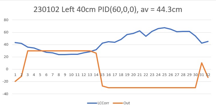
This worked, ‘sorta’. Part of the problem with this run is the robot’s orientation with respect to the wall at the start of the run. This is supposed to be parallel with the wall, but it obviously isn’t, and I don’t know why. Here’s the data from the ‘RotateToParallelOrientation()’ step
|
1 2 3 4 5 6 7 8 9 10 11 12 13 14 15 16 17 18 19 20 21 22 23 24 25 |
In RotateToParallelOrientation(Left) with Kp/Ki/Kd = 20.0/4.0/0.0 Msec Hdg FrontD RearD Steer PSteer err Ival Out speed 108955 27.61 39.40 36.60 0.28 0.00 -0.28 -1.12 -6.72 -6 109155 27.61 40.30 37.10 0.32 0.28 -0.32 -2.40 -8.80 -8 109355 27.61 38.80 36.50 0.23 0.32 -0.23 -3.32 -7.92 -7 109555 27.61 39.50 36.00 0.35 0.23 -0.35 -4.72 -11.72 -11 109755 27.61 40.00 36.90 0.31 0.35 -0.31 -5.96 -12.16 -12 109955 27.61 40.00 37.30 0.27 0.31 -0.27 -7.04 -12.44 -12 110155 27.61 39.80 36.30 0.35 0.27 -0.35 -8.44 -15.44 -15 110355 27.61 40.20 37.00 0.32 0.35 -0.32 -9.72 -16.12 -16 110555 27.61 39.40 36.50 0.29 0.32 -0.29 -10.88 -16.68 -16 110755 27.61 40.30 36.50 0.38 0.29 -0.38 -12.40 -20.00 -20 110955 27.61 40.30 36.80 0.35 0.38 -0.35 -13.80 -20.80 -20 111155 27.61 40.30 35.80 0.45 0.35 -0.45 -15.60 -24.60 -24 111355 27.61 39.90 36.40 0.35 0.45 -0.35 -17.00 -24.00 -24 111555 27.61 38.90 36.00 0.29 0.35 -0.29 -18.16 -23.96 -23 111755 27.61 37.20 35.40 0.18 0.29 -0.18 -18.88 -22.48 -22 111955 27.61 37.70 35.80 0.15 0.18 -0.15 -19.48 -22.48 -22 112155 27.61 37.70 35.70 0.20 0.15 -0.20 -20.28 -24.28 -24 112355 27.61 38.20 36.00 0.22 0.20 -0.22 -21.16 -25.56 -25 112555 27.61 37.50 37.00 0.05 0.22 -0.05 -21.36 -22.36 -22 112755 27.61 38.20 37.70 0.05 0.05 -0.05 -21.56 -22.56 -22 112955 27.61 39.00 38.80 0.02 0.05 -0.02 -21.64 -22.04 -22 113155 27.61 39.40 39.70 -0.03 0.02 0.03 -21.52 -20.92 -20 Exited RTPO coarse tune with hdg/steerval/prev_steerval = 27.6/-0.0/0.0 |
This certainly looks good – with a front/rear distance difference of only 0.3cm, and a steering value of 0.02. However, as shown in the following screengrab of the above video, the robot’s orientation just after the parallel find operation is anything but parallel
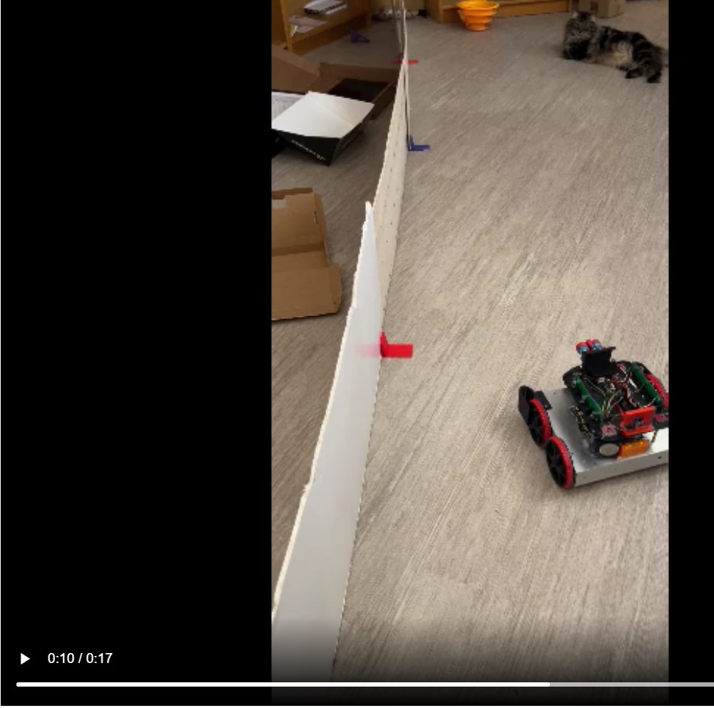
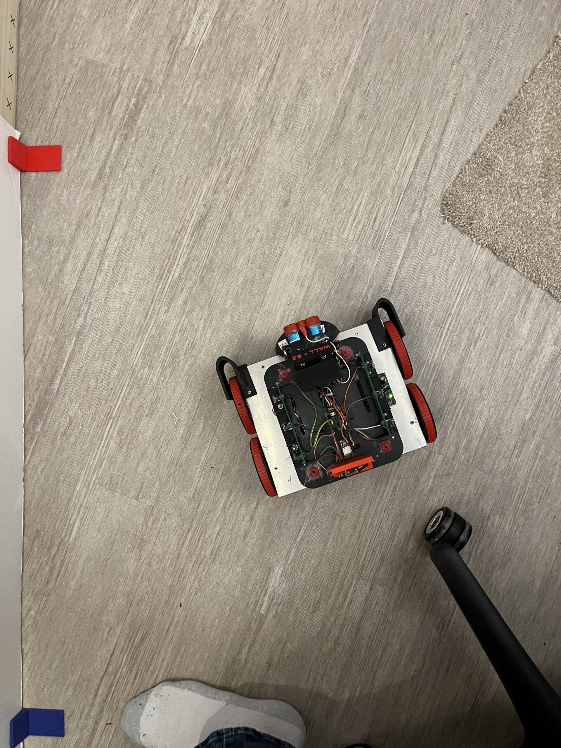
I re-instrumented the ‘RotateToParallelOrientation’ function to print out 10 sets of front/back distances directly after completing it’s ‘ParallelFind’ operation, and made another run. The photo below shows the ending orientation, followed by the data
|
1 2 3 4 5 6 7 8 9 10 11 12 13 14 15 16 17 18 19 20 21 22 23 24 25 26 27 28 29 30 31 32 33 34 |
In RotateToParallelOrientation(Left) with Kp/Ki/Kd = 20.0/4.0/0.0 Msec Hdg FrontD RearD Steer PSteer err Ival Out speed 33846 36.67 54.60 49.30 0.53 0.00 -0.53 -2.12 -12.72 -12 34046 36.67 54.90 50.10 0.48 0.53 -0.48 -4.04 -13.64 -13 34246 36.67 55.40 50.60 0.48 0.48 -0.48 -5.96 -15.56 -15 34446 36.67 56.60 50.10 0.65 0.48 -0.65 -8.56 -21.56 -21 34646 36.67 53.80 49.20 0.46 0.65 -0.46 -10.40 -19.60 -19 34846 36.67 54.10 48.50 0.56 0.46 -0.56 -12.64 -23.84 -23 35046 36.67 51.10 47.60 0.35 0.56 -0.35 -14.04 -21.04 -21 35246 36.67 49.90 46.30 0.36 0.35 -0.36 -15.48 -22.68 -22 35446 36.67 48.20 45.10 0.31 0.36 -0.31 -16.72 -22.92 -22 35646 36.67 46.70 43.90 0.28 0.31 -0.28 -17.84 -23.44 -23 35846 36.67 45.30 42.30 0.30 0.28 -0.30 -19.04 -25.04 -25 36046 36.67 43.80 41.30 0.25 0.30 -0.25 -20.04 -25.04 -25 36246 36.67 42.80 41.20 0.16 0.25 -0.16 -20.68 -23.88 -23 36446 36.67 42.10 40.90 0.12 0.16 -0.12 -21.16 -23.56 -23 36646 36.67 41.90 39.70 0.22 0.12 -0.22 -22.04 -26.44 -26 36846 36.67 41.60 39.80 0.18 0.22 -0.18 -22.76 -26.36 -26 37046 36.67 40.90 40.40 0.05 0.18 -0.05 -22.96 -23.96 -23 37246 36.67 40.50 40.30 0.02 0.05 -0.02 -23.04 -23.44 -23 37446 36.67 41.80 40.80 0.10 0.02 -0.10 -23.44 -25.44 -25 37646 36.67 42.40 42.00 0.04 0.10 -0.04 -23.60 -24.40 -24 37846 36.67 42.50 43.30 -0.08 0.04 0.08 -23.28 -21.68 -21 Exited RTPO coarse tune with hdg/steerval/prev_steerval = 36.67/-0.08/0.04 37854 36.67 42.50 43.30 -0.08 38057 36.67 44.00 44.50 -0.05 38259 36.67 44.00 44.10 -0.01 38462 36.67 43.50 44.00 -0.05 38664 36.67 43.50 44.10 -0.06 38867 36.67 43.20 44.00 -0.08 39069 36.67 43.50 44.30 -0.08 39272 36.67 43.50 44.30 -0.08 39474 36.67 44.40 44.50 -0.01 39676 36.67 44.40 44.20 0.02 |
According to the photo, the robot is definitely not oriented parallel to the wall. However, according to the telemetry data, it is (44.4 front, 44.2 rear, steerval = 0.02). Even curioser, the actual physical measurements taken using a tape measure show that the front/rear distances are about 47/44cm, or a steerval of about 0.3! Something is definitely wrong here.
Uncommented the #DISTANCES_ONLY define and re-ran, with the robot position/orientation unchanged:
|
1 2 3 4 5 6 7 8 9 10 11 12 13 14 15 16 17 18 19 20 21 22 23 24 25 26 27 28 29 30 31 32 33 34 35 36 |
Msec LFront LCenter LRear RFront RCenter RRear Rear LSteer RSteer LIDAR 8150 44.60 46.00 44.40 56.00 58.70 785.60 91.30 0.020 -72.960 0.00 8302 43.30 45.80 44.10 56.00 58.40 785.60 82.30 -0.080 -72.960 0.00 8502 44.00 45.80 44.70 56.90 59.50 785.60 85.60 -0.070 -72.870 0.00 8702 43.50 45.70 44.10 56.90 59.80 785.60 86.10 -0.060 -72.870 0.00 8902 43.70 46.00 44.30 56.80 58.70 785.60 94.60 -0.060 -72.880 0.00 9102 44.20 46.00 45.10 56.90 60.10 785.60 93.10 -0.090 -72.870 0.00 9302 43.00 46.70 44.70 56.30 56.80 785.60 80.50 -0.170 -72.800 0.00 9502 44.10 45.60 45.20 56.70 59.90 785.60 91.60 -0.110 -72.890 0.00 9702 44.10 46.00 44.30 56.90 59.80 785.60 81.00 -0.070 -72.870 0.00 9902 44.50 45.70 44.40 56.10 60.40 785.60 93.00 0.010 -72.950 0.00 10102 44.60 46.20 44.40 57.00 58.20 785.60 82.80 0.020 -72.860 0.00 10302 43.50 45.70 45.30 57.70 57.20 785.60 91.10 -0.180 -72.790 0.00 10502 44.20 46.30 44.50 58.00 58.40 785.60 80.00 -0.030 -72.760 0.00 10702 42.60 47.00 45.30 57.40 59.60 785.60 90.40 -0.270 -72.820 0.00 10902 43.50 45.60 45.20 56.30 59.40 785.60 84.60 -0.170 -72.930 0.00 11102 44.00 46.60 45.00 56.20 58.90 72.60 92.10 -0.100 -1.640 0.00 11302 42.70 46.30 44.90 57.30 58.40 785.60 80.80 -0.220 -72.830 0.00 11502 44.00 45.70 44.80 56.00 58.20 785.60 93.90 -0.080 -72.960 0.00 11702 43.20 46.00 44.70 57.70 58.30 785.60 81.40 -0.150 -72.790 0.00 Msec LFront LCenter LRear RFront RCenter RRear Rear LSteer RSteer LIDAR 11902 43.50 46.00 44.80 56.90 58.60 785.60 96.80 -0.130 -72.870 0.00 12102 43.40 45.50 44.20 56.60 59.60 785.60 81.80 -0.080 -72.900 0.00 12302 44.30 45.50 45.30 57.10 59.40 785.60 88.40 -0.100 -72.850 0.00 12502 43.80 45.30 45.10 56.90 58.50 785.60 88.60 -0.130 -72.870 0.00 12702 43.70 46.30 44.90 57.70 60.50 785.60 85.20 -0.120 -72.830 0.00 12902 43.50 45.70 45.10 56.10 60.00 785.60 97.40 -0.160 -72.950 0.00 13102 43.50 46.20 44.50 55.90 61.10 785.60 84.60 -0.100 -72.970 0.00 13302 44.00 46.40 44.60 57.60 61.60 785.60 93.60 -0.060 -72.800 0.00 13502 43.40 46.80 44.40 56.40 59.00 785.60 81.60 -0.100 -72.920 0.00 13702 43.60 46.40 44.30 56.50 60.50 785.60 91.90 -0.070 -72.910 0.00 13902 43.20 46.20 45.50 56.10 60.10 785.60 81.70 -0.230 -72.950 0.00 14102 43.40 46.80 44.80 56.40 59.50 67.30 91.70 -0.140 -1.090 0.00 14302 43.50 46.10 45.10 57.00 58.40 785.60 80.60 -0.160 -72.860 0.00 14502 44.50 46.50 45.00 56.10 58.60 785.60 90.90 -0.050 -72.950 0.00 |
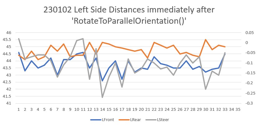
In the above data, the front distance varies from 42.6 to 44.6cm with an average of 43.7cm, and the rear distance varies from 44.1 to 45.5cm with an average of 44.8cm.
So the program thinks the front/back distances are closer together than the tape measure does (44.5/45.0 vs 47/44). This is a pretty big discrepancy. Rotating the robot to be physically parallel with front/rear distances = 40cm, I get:
|
1 2 3 4 5 6 7 8 9 10 11 12 13 14 15 16 |
Msec LFront LCenter LRear RFront RCenter RRear Rear LSteer RSteer LIDAR 287902 38.40 41.10 38.10 78.60 92.40 785.60 819.00 0.030 -70.700 0.00 288102 38.70 40.50 38.20 76.70 94.20 785.60 750.30 0.050 -70.890 0.00 288302 39.00 40.40 38.30 77.10 93.40 785.60 819.00 0.070 -70.850 0.00 288502 38.60 40.70 38.30 78.70 93.50 785.60 819.00 0.030 -70.690 0.00 288702 39.20 40.50 38.10 75.80 92.70 785.60 750.30 0.110 -70.750 0.00 288902 38.90 41.60 37.70 78.10 91.90 92.20 819.00 0.120 -1.410 0.00 289102 38.30 40.80 38.10 77.90 92.70 87.60 750.30 0.020 -0.970 0.00 289302 38.20 41.40 37.60 78.50 92.00 785.60 819.00 0.060 -70.710 0.00 289502 39.60 40.50 37.90 79.20 91.40 84.90 750.30 0.170 -0.570 0.00 289702 39.20 40.40 38.30 76.70 94.80 785.60 819.00 0.090 -70.890 0.00 289902 38.90 39.50 38.00 78.10 92.70 92.70 750.30 0.090 -1.460 0.00 290102 39.10 41.10 37.70 78.00 92.40 785.60 819.00 0.140 -70.760 0.00 290302 38.50 40.60 38.10 77.50 93.50 785.60 750.30 0.040 -70.810 0.00 290502 38.80 41.10 36.70 77.10 93.10 95.00 819.00 0.210 -1.790 0.00 290702 38.90 41.30 37.50 77.30 93.10 91.70 750.30 0.140 -1.440 0.00 |
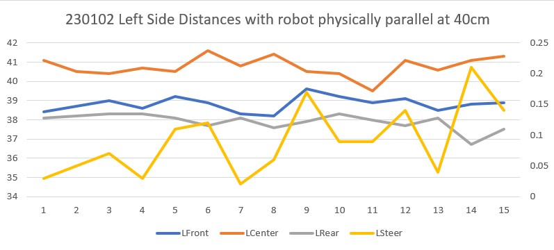
When the robot is physically parallel, the reported front distance varies from 38.2 to 39.2cm with an average of 38.8cm, and the rear distance varies from 36.7 to 38.3cm with an average of 37.9. The left steering value varies from 0.02 (38.8/38.1) to 0.14 (38.9/37.5) with an average of 0.09.
Well, it looks like the average reported distances and steering values are pretty close to reality, so maybe my original calibration efforts aren’t entirely screwed up. However, it is abundantly clear at this point that my current ‘RotateToParallelOrientation()’ algorithm isn’t reliable, due to very noisy distance value measurements.
01/09/23 Update:
After getting ‘RotateToParallelOrientation()’ working better (now it just uses the array front/rear distance measurements to calculate the off-parallel angle, and then does a ‘SpinTurn’ by that amount), I resumed the effort (see the 02 January Update above) trying to determine if my older algorithm for combining the raw steering value with an ‘offset adjustment factor’ based on the robot’s distance from the desired offset distance would now work better given the improvements I have made in VL53L0X sensor error compensation and off-parallel distance measurement compensation.
As it turns out, the answer seems to be ‘no’. After a multitude of runs with my test wall set up for two 30-45deg ‘breaks’, I couldn’t find any set of PID values that would allow the robot to track the wall – it always either took off for parts unknown, or crashed into the wall at some point.
So, back to the original algorithm of using the wall offset distance directly in the PID engine.
11 January 2023 Update:
I’m confused – not an unusual state for me to be in – but still…..
After all the above improvements, I still was unable to produce reasonable tracking performance using either the steering value or the offset distance as the parameter to be controlled. And, even more confusing, I have an entire post dedicated to demonstrating successful wall tracking using the orientation-angle-corrected distance to the wall as the input to the PID engine, with the desired wall offset as the setpoint, as shown here:
|
1 2 |
WallTrackOutput = PIDCalcs(glLeftCentCorrCm, WallTrackSetPoint, lastError, lastInput, lastIval, lastDerror, kp, ki, kd); |
With this algorithm, I settled on PID(3,0,1) as the best parameter set, with the result shown in this short video (copied from the above post):
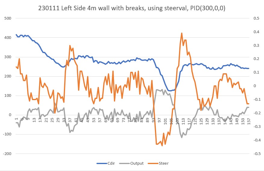
And then, I have another post demonstrating that using the steering value as input and 0 as the setpoint also works, as shown in this short video with PID(300,0,300)
Here’s the data and short video from a run on my longer ‘4 meter’ test range with two 30º breaks:
|
1 2 3 4 5 6 7 8 9 10 11 12 13 14 15 16 17 18 19 20 21 22 23 24 25 26 27 28 29 30 31 32 33 34 35 36 37 38 39 40 41 42 43 44 45 46 47 48 49 50 51 52 53 54 55 56 57 58 59 60 61 62 63 64 65 66 67 68 69 70 71 72 73 74 75 76 77 78 79 80 81 82 83 84 85 86 87 88 89 90 91 92 93 94 95 96 97 98 99 100 101 102 103 104 105 106 107 108 109 110 111 112 113 114 115 116 117 118 119 120 121 122 123 124 125 126 127 128 129 130 131 132 133 134 135 136 137 138 139 140 141 142 143 144 145 146 147 148 149 150 151 152 153 154 155 156 157 158 159 160 161 162 163 164 165 166 167 168 169 170 171 172 173 174 175 176 177 178 179 180 181 182 183 184 185 186 187 188 189 190 191 192 193 194 195 196 197 198 199 200 201 202 203 204 205 206 207 208 209 210 211 212 213 214 |
In TrackLeftWallOffset with Kp/Ki/Kd = 300.00 0.00 0.00 R/C/F dists = 136 117 127 Steerval = -0.090, CutAngle = 29.00 (cutAngleDeg > 0 && abs(cutAngleDeg) < 30 -- setting to +30 R/C/F dists = 136 117 127 Steerval = -0.090, SteerAngle = -5.14, CutAngle = 30.00 CutAngDeg > 0, SteerAngleDeg < cutAngleDeg In SpinTurn(CW, 35.14, 30.00) Init hdg = -0.08 deg, Turn = 35.14 deg, tgt = 35.06 deg, timeout = 2.34 sec Msec Hdg PrvHdg dHdg Rate tgtDPS err Kp*err Ival Kd*Derr speed Match Slope 11361 0.05 -0.08 0.13 4.49 30.00 25.51 45.92 25.51 10.20 61 0.81 0.81 11391 1.28 0.05 1.23 40.88 30.00 -10.88 -19.58 14.63 -14.56 50 0.81 0.01 11421 3.31 1.28 2.03 67.70 30.00 -37.70 -67.86 0.00 -10.73 50 0.82 0.01 11451 5.52 3.31 2.22 73.85 30.00 -43.85 -78.94 0.00 -2.46 50 0.84 0.01 11481 7.87 5.52 2.34 78.13 30.00 -48.13 -86.64 0.00 -1.71 50 0.85 0.01 11511 10.30 7.87 2.43 81.05 30.00 -51.05 -91.89 0.00 -1.17 50 0.86 0.01 11541 12.83 10.30 2.53 84.47 30.00 -54.47 -98.05 0.00 -1.37 50 0.88 0.01 11571 15.41 12.83 2.58 85.85 30.00 -55.85 -100.54 0.00 -0.55 50 0.89 0.01 11601 18.03 15.41 2.62 87.32 30.00 -57.32 -103.18 0.00 -0.59 50 0.91 0.01 11631 20.70 18.03 2.67 89.17 30.00 -59.17 -106.50 0.00 -0.74 50 0.92 0.01 11661 23.36 20.70 2.66 88.50 30.00 -58.50 -105.30 0.00 0.27 50 0.93 0.01 11691 26.02 23.36 2.66 88.82 30.00 -58.82 -105.87 0.00 -0.13 50 0.95 0.01 11721 28.79 26.02 2.76 92.13 30.00 -62.13 -111.83 0.00 -1.32 50 0.97 0.02 11751 31.48 28.79 2.69 89.76 30.00 -59.76 -107.57 0.00 0.94 50 0.98 0.01 11781 34.20 31.48 2.72 90.74 30.00 -60.74 -109.33 0.00 -0.39 50 1.00 0.02 Completed turn with yaw = 34.20, tgt = 35.06, and match = 0.995 fudgeFactorMM = -100 at approach start: cut angle = 30.000, adjfactor = 0.866, num = 400.00, tgt dist = 361.88 At start - err = prev_err = -138 R/C/F dists = 156 208 223 Steerval = 0.670, SteerAngle = 38.29, CutAngle = 30.00, err/prev_err = -138 Msec LFront LCtr LRear Front Rear Err P_err 13913 228 206 155 170 206 -133 -138 14020 250 231 179 173 243 -111 -133 14127 312 310 237 168 304 -49 -111 14234 381 395 313 159 393 19 -49 At end of offset capture - prev_res*res = -931 correct back to parallel In SpinTurn(CCW, 30.00, 30.00) Init hdg = 45.41 deg, Turn = 30.00 deg, tgt = 15.41 deg, timeout = 2.00 sec Msec Hdg PrvHdg dHdg Rate tgtDPS err Kp*err Ival Kd*Derr speed Match Slope 14294 45.26 45.41 -0.15 5.12 30.00 24.88 44.79 24.88 9.95 59 0.83 0.83 14324 44.29 45.26 -0.98 32.52 30.00 -2.52 -4.53 22.37 -10.96 50 0.84 0.01 14354 42.61 44.29 -1.68 55.95 30.00 -25.95 -46.71 0.00 -9.37 50 0.85 0.01 14384 40.64 42.61 -1.96 65.48 30.00 -35.48 -63.87 0.00 -3.81 50 0.86 0.01 14414 38.30 40.64 -2.34 78.08 30.00 -48.08 -86.55 0.00 -5.04 50 0.87 0.01 14444 35.51 38.30 -2.79 92.90 30.00 -62.90 -113.22 0.00 -5.93 50 0.89 0.02 14474 32.31 35.51 -3.21 106.88 30.00 -76.88 -138.39 0.00 -5.59 50 0.91 0.02 14504 28.88 32.31 -3.42 114.15 30.00 -84.15 -151.47 0.00 -2.91 50 0.93 0.02 14534 25.25 28.88 -3.64 121.22 30.00 -91.22 -164.19 0.00 -2.83 50 0.95 0.02 14564 21.33 25.25 -3.91 130.41 30.00 -100.41 -180.74 0.00 -3.68 50 0.97 0.02 14594 17.50 21.33 -3.84 127.92 30.00 -97.92 -176.26 0.00 1.00 50 0.99 0.02 14624 13.63 17.50 -3.87 128.94 30.00 -98.94 -178.09 0.00 -0.41 50 0.99 0.00 Completed turn with yaw = 13.63, tgt = 15.41, and match = 0.990 TrackLeftWallOffset: Start tracking offset of 40.00cm with Kp/Ki/Kd = 300.00 0.00 0.00 Msec Fdir Cdir Rdir Steer Set error Ival Kp*err Ki*Ival Kd*Din Output Lspd Rspd 15692 389 416 377 0.14 0.00 -0.14 0.00 -40.80 0.00 -0.00 -40.80 34 115 15742 390 404 377 0.13 0.00 -0.13 0.00 -40.20 0.00 0.00 -40.20 34 115 15792 391 405 371 0.20 0.00 -0.20 0.00 -61.50 0.00 -0.00 -61.50 13 136 15842 386 412 378 0.09 0.00 -0.09 0.00 -27.60 0.00 0.00 -27.60 47 102 15892 386 412 378 0.09 0.00 -0.09 0.00 -27.60 0.00 0.00 -27.60 47 102 15942 386 405 383 0.04 0.00 -0.04 0.00 -10.50 0.00 0.00 -10.50 64 85 15992 386 413 383 0.04 0.00 -0.04 0.00 -12.90 0.00 -0.00 -12.90 62 87 16042 388 407 381 0.08 0.00 -0.08 0.00 -23.10 0.00 -0.00 -23.10 51 98 16092 381 411 388 -0.06 0.00 0.06 0.00 17.70 0.00 0.00 17.70 92 57 16142 370 403 381 -0.11 0.00 0.11 0.00 32.10 0.00 0.00 32.10 107 42 16192 376 394 380 -0.05 0.00 0.05 0.00 13.80 0.00 -0.00 13.80 88 61 16242 366 384 374 -0.10 0.00 0.10 0.00 28.80 0.00 0.00 28.80 103 46 16292 362 384 374 -0.10 0.00 0.10 0.00 28.80 0.00 0.00 28.80 103 46 16342 362 375 370 -0.10 0.00 0.10 0.00 31.50 0.00 0.00 31.50 106 43 16392 351 372 357 -0.09 0.00 0.09 0.00 26.40 0.00 -0.00 26.40 101 48 16442 337 364 346 -0.13 0.00 0.13 0.00 37.80 0.00 0.00 37.80 112 37 16492 332 352 321 0.06 0.00 -0.06 0.00 -18.60 0.00 -0.00 -18.60 56 93 16542 325 336 319 -0.00 0.00 0.00 0.00 1.20 0.00 0.00 1.20 76 73 16592 315 323 308 -0.01 0.00 0.01 0.00 2.10 0.00 0.00 2.10 77 72 16642 310 324 300 0.02 0.00 -0.02 0.00 -7.20 0.00 -0.00 -7.20 67 82 16692 310 314 301 0.00 0.00 -0.00 0.00 -1.20 0.00 0.00 -1.20 73 76 16742 302 304 293 -0.01 0.00 0.01 0.00 1.80 0.00 0.00 1.80 76 73 16792 294 301 290 -0.06 0.00 0.06 0.00 17.70 0.00 0.00 17.70 92 57 16842 289 295 288 -0.09 0.00 0.09 0.00 28.50 0.00 0.00 28.50 103 46 16892 283 289 279 -0.07 0.00 0.07 0.00 21.30 0.00 -0.00 21.30 96 53 16942 283 287 275 -0.03 0.00 0.03 0.00 9.90 0.00 -0.00 9.90 84 65 16992 269 277 277 -0.20 0.00 0.20 0.00 60.90 0.00 0.00 60.90 135 14 17042 270 269 272 -0.15 0.00 0.15 0.00 45.30 0.00 -0.00 45.30 120 29 17092 263 268 255 -0.05 0.00 0.05 0.00 15.60 0.00 -0.00 15.60 90 59 17142 257 261 253 -0.06 0.00 0.06 0.00 17.70 0.00 0.00 17.70 92 57 17192 243 253 237 -0.09 0.00 0.09 0.00 26.10 0.00 0.00 26.10 101 48 17242 250 248 243 -0.08 0.00 0.08 0.00 24.60 0.00 -0.00 24.60 99 50 17292 241 249 238 -0.12 0.00 0.12 0.00 36.30 0.00 0.00 36.30 111 38 17342 259 255 234 0.11 0.00 -0.11 0.00 -31.50 0.00 -0.00 -31.50 43 106 17392 270 261 237 0.19 0.00 -0.19 0.00 -57.30 0.00 -0.00 -57.30 17 132 17442 273 269 245 0.15 0.00 -0.15 0.00 -44.70 0.00 0.00 -44.70 30 119 17492 287 282 245 0.30 0.00 -0.30 0.00 -90.60 0.00 -0.00 -90.60 0 165 17542 293 293 256 0.26 0.00 -0.26 0.00 -78.90 0.00 0.00 -78.90 0 153 17592 299 288 260 0.28 0.00 -0.28 0.00 -83.40 0.00 -0.00 -83.40 0 158 17642 302 292 272 0.19 0.00 -0.19 0.00 -57.60 0.00 0.00 -57.60 17 132 17692 300 292 272 0.17 0.00 -0.17 0.00 -51.60 0.00 0.00 -51.60 23 126 17742 302 290 276 0.15 0.00 -0.15 0.00 -45.00 0.00 0.00 -45.00 30 120 17792 288 306 282 -0.03 0.00 0.03 0.00 10.20 0.00 0.00 10.20 85 64 17842 298 305 278 0.11 0.00 -0.11 0.00 -31.50 0.00 -0.00 -31.50 43 106 17892 302 300 281 0.11 0.00 -0.11 0.00 -33.00 0.00 -0.00 -33.00 42 108 17942 304 305 288 0.06 0.00 -0.06 0.00 -19.50 0.00 0.00 -19.50 55 94 17992 302 296 292 -0.00 0.00 0.00 0.00 1.20 0.00 0.00 1.20 76 73 18042 294 307 288 -0.03 0.00 0.03 0.00 9.90 0.00 0.00 9.90 84 65 18092 301 307 285 0.07 0.00 -0.07 0.00 -20.10 0.00 -0.00 -20.10 54 95 18142 291 299 289 -0.08 0.00 0.08 0.00 24.30 0.00 0.00 24.30 99 50 18192 294 297 286 -0.02 0.00 0.02 0.00 6.90 0.00 -0.00 6.90 81 68 18242 283 300 283 -0.10 0.00 0.10 0.00 30.00 0.00 0.00 30.00 105 45 18292 290 274 290 -0.13 0.00 0.13 0.00 37.80 0.00 0.00 37.80 112 37 18342 280 281 277 -0.09 0.00 0.09 0.00 26.70 0.00 -0.00 26.70 101 48 18392 272 279 269 -0.09 0.00 0.09 0.00 27.30 0.00 0.00 27.30 102 47 18442 272 267 260 -0.01 0.00 0.01 0.00 3.90 0.00 -0.00 3.90 78 71 18492 269 275 267 -0.11 0.00 0.11 0.00 31.50 0.00 0.00 31.50 106 43 18542 268 274 264 -0.09 0.00 0.09 0.00 25.80 0.00 -0.00 25.80 100 49 18592 267 271 263 -0.09 0.00 0.09 0.00 26.70 0.00 0.00 26.70 101 48 18642 272 267 257 0.02 0.00 -0.02 0.00 -5.10 0.00 -0.00 -5.10 69 80 18692 269 262 248 0.07 0.00 -0.07 0.00 -21.60 0.00 -0.00 -21.60 53 96 18742 268 267 254 0.01 0.00 -0.01 0.00 -2.10 0.00 0.00 -2.10 72 77 18792 268 276 247 0.09 0.00 -0.09 0.00 -25.80 0.00 -0.00 -25.80 49 100 18842 271 267 258 -0.00 0.00 0.00 0.00 0.90 0.00 0.00 0.90 75 74 18892 264 270 256 -0.05 0.00 0.05 0.00 15.00 0.00 0.00 15.00 90 60 18942 272 268 248 0.11 0.00 -0.11 0.00 -32.40 0.00 -0.00 -32.40 42 107 18992 258 272 256 -0.11 0.00 0.11 0.00 32.40 0.00 0.00 32.40 107 42 19042 266 264 251 0.01 0.00 -0.01 0.00 -4.20 0.00 -0.00 -4.20 70 79 19092 262 265 253 -0.05 0.00 0.05 0.00 13.50 0.00 0.00 13.50 88 61 19142 265 274 253 -0.01 0.00 0.01 0.00 1.80 0.00 -0.00 1.80 76 73 19192 272 266 259 -0.00 0.00 0.00 0.00 1.20 0.00 -0.00 1.20 76 73 19242 268 273 264 -0.09 0.00 0.09 0.00 26.10 0.00 0.00 26.10 101 48 19292 274 279 263 -0.01 0.00 0.01 0.00 3.30 0.00 -0.00 3.30 78 71 19342 272 274 258 0.01 0.00 -0.01 0.00 -4.20 0.00 -0.00 -4.20 70 79 19392 280 276 269 -0.01 0.00 0.01 0.00 4.20 0.00 0.00 4.20 79 70 19442 282 283 264 0.06 0.00 -0.06 0.00 -18.90 0.00 -0.00 -18.90 56 93 19492 275 276 266 -0.03 0.00 0.03 0.00 10.20 0.00 0.00 10.20 85 64 19542 287 285 265 0.10 0.00 -0.10 0.00 -31.50 0.00 -0.00 -31.50 43 106 19592 287 285 265 0.10 0.00 -0.10 0.00 -31.50 0.00 0.00 -31.50 43 106 19642 286 286 267 0.05 0.00 -0.05 0.00 -13.80 0.00 0.00 -13.80 61 88 19692 289 281 267 0.10 0.00 -0.10 0.00 -30.30 0.00 -0.00 -30.30 44 105 19742 283 296 274 -0.01 0.00 0.01 0.00 4.20 0.00 0.00 4.20 79 70 19792 293 290 271 0.11 0.00 -0.11 0.00 -33.00 0.00 -0.00 -33.00 42 108 19842 289 290 284 -0.06 0.00 0.06 0.00 18.00 0.00 0.00 18.00 93 57 19892 293 284 275 0.06 0.00 -0.06 0.00 -19.20 0.00 -0.00 -19.20 55 94 19942 294 283 277 0.05 0.00 -0.05 0.00 -15.90 0.00 0.00 -15.90 59 90 19992 284 285 272 0.00 0.00 -0.00 0.00 -1.50 0.00 0.00 -1.50 73 76 20042 288 284 278 -0.02 0.00 0.02 0.00 4.80 0.00 0.00 4.80 79 70 20092 284 279 278 -0.06 0.00 0.06 0.00 18.30 0.00 0.00 18.30 93 56 20142 291 290 280 0.00 0.00 0.00 0.00 0.00 0.00 -0.00 0.00 75 75 20192 285 284 281 -0.08 0.00 0.08 0.00 22.80 0.00 0.00 22.80 97 52 20242 291 290 276 0.04 0.00 -0.04 0.00 -12.00 0.00 -0.00 -12.00 63 87 20292 285 286 285 -0.11 0.00 0.11 0.00 34.20 0.00 0.00 34.20 109 40 20342 268 268 282 -0.27 0.00 0.27 0.00 81.60 0.00 0.00 81.60 156 0 20392 248 246 276 -0.43 0.00 0.43 0.00 130.20 0.00 0.00 130.20 200 0 20442 248 246 276 -0.43 0.00 0.43 0.00 130.20 0.00 0.00 130.20 200 0 20492 227 236 253 -0.42 0.00 0.42 0.00 127.20 0.00 -0.00 127.20 200 0 20542 215 209 237 -0.41 0.00 0.41 0.00 123.30 0.00 -0.00 123.30 198 0 20592 198 204 222 -0.44 0.00 0.44 0.00 130.80 0.00 0.00 130.80 200 0 20642 185 181 198 -0.35 0.00 0.35 0.00 104.70 0.00 -0.00 104.70 179 0 20692 171 160 190 -0.43 0.00 0.43 0.00 129.00 0.00 0.00 129.00 200 0 20742 161 143 173 -0.38 0.00 0.38 0.00 113.10 0.00 -0.00 113.10 188 0 20792 151 127 158 -0.34 0.00 0.34 0.00 102.90 0.00 -0.00 102.90 177 0 20842 140 126 149 -0.36 0.00 0.36 0.00 109.20 0.00 0.00 109.20 184 0 20892 140 126 141 -0.28 0.00 0.28 0.00 85.20 0.00 -0.00 85.20 160 0 20942 152 129 142 -0.17 0.00 0.17 0.00 51.30 0.00 -0.00 51.30 126 23 20992 152 129 142 -0.17 0.00 0.17 0.00 51.30 0.00 0.00 51.30 126 23 21042 169 136 144 -0.01 0.00 0.01 0.00 4.20 0.00 -0.00 4.20 79 70 21092 186 156 149 0.13 0.00 -0.13 0.00 -37.80 0.00 -0.00 -37.80 37 112 21142 201 176 164 0.15 0.00 -0.15 0.00 -43.80 0.00 -0.00 -43.80 31 118 21192 230 223 181 0.31 0.00 -0.31 0.00 -93.90 0.00 -0.00 -93.90 0 168 21242 255 230 199 0.39 0.00 -0.39 0.00 -117.00 0.00 -0.00 -117.00 0 192 21292 261 254 216 0.30 0.00 -0.30 0.00 -91.20 0.00 0.00 -91.20 0 166 21342 275 260 227 0.34 0.00 -0.34 0.00 -102.00 0.00 -0.00 -102.00 0 177 21392 274 260 227 0.34 0.00 -0.34 0.00 -102.00 0.00 0.00 -102.00 0 177 21442 274 255 236 0.23 0.00 -0.23 0.00 -70.50 0.00 0.00 -70.50 4 145 21492 280 264 241 0.25 0.00 -0.25 0.00 -76.20 0.00 -0.00 -76.20 0 151 21542 275 265 240 0.21 0.00 -0.21 0.00 -64.50 0.00 0.00 -64.50 10 139 21592 275 261 250 0.11 0.00 -0.11 0.00 -33.30 0.00 0.00 -33.30 41 108 21642 273 260 253 0.06 0.00 -0.06 0.00 -18.00 0.00 0.00 -18.00 57 93 21692 275 263 258 0.03 0.00 -0.03 0.00 -9.90 0.00 0.00 -9.90 65 84 21742 274 265 263 -0.03 0.00 0.03 0.00 7.50 0.00 0.00 7.50 82 67 21792 273 261 269 -0.10 0.00 0.10 0.00 29.70 0.00 0.00 29.70 104 45 21842 273 261 269 -0.10 0.00 0.10 0.00 29.70 0.00 0.00 29.70 104 45 21892 272 265 276 -0.18 0.00 0.18 0.00 52.50 0.00 0.00 52.50 127 22 21942 268 263 263 -0.09 0.00 0.09 0.00 26.10 0.00 -0.00 26.10 101 48 21992 265 256 266 -0.15 0.00 0.15 0.00 46.20 0.00 0.00 46.20 121 28 22042 257 255 257 -0.14 0.00 0.14 0.00 43.50 0.00 -0.00 43.50 118 31 22092 256 243 252 -0.12 0.00 0.12 0.00 35.10 0.00 -0.00 35.10 110 39 22142 254 245 247 -0.09 0.00 0.09 0.00 25.50 0.00 -0.00 25.50 100 49 22192 250 237 249 -0.15 0.00 0.15 0.00 45.90 0.00 0.00 45.90 120 29 22242 248 237 243 -0.11 0.00 0.11 0.00 33.90 0.00 -0.00 33.90 108 41 22292 250 245 242 -0.08 0.00 0.08 0.00 22.50 0.00 -0.00 22.50 97 52 22342 258 236 242 -0.00 0.00 0.00 0.00 1.20 0.00 -0.00 1.20 76 73 22392 258 236 242 -0.00 0.00 0.00 0.00 1.20 0.00 0.00 1.20 76 73 22442 251 239 244 -0.09 0.00 0.09 0.00 27.30 0.00 0.00 27.30 102 47 22492 265 245 247 0.03 0.00 -0.03 0.00 -7.50 0.00 -0.00 -7.50 67 82 22542 262 239 241 0.05 0.00 -0.05 0.00 -14.70 0.00 -0.00 -14.70 60 89 22592 272 243 252 0.04 0.00 -0.04 0.00 -12.90 0.00 0.00 -12.90 62 87 22642 271 255 248 0.09 0.00 -0.09 0.00 -25.50 0.00 -0.00 -25.50 49 100 22692 276 255 252 0.09 0.00 -0.09 0.00 -28.50 0.00 -0.00 -28.50 46 103 22742 281 257 258 0.09 0.00 -0.09 0.00 -26.10 0.00 0.00 -26.10 48 101 22792 276 259 259 0.03 0.00 -0.03 0.00 -8.70 0.00 0.00 -8.70 66 83 22842 280 255 259 0.06 0.00 -0.06 0.00 -19.50 0.00 -0.00 -19.50 55 94 22892 279 265 260 0.05 0.00 -0.05 0.00 -16.50 0.00 0.00 -16.50 58 91 22942 279 260 266 -0.01 0.00 0.01 0.00 3.00 0.00 0.00 3.00 78 72 22992 277 259 261 0.02 0.00 -0.02 0.00 -5.70 0.00 -0.00 -5.70 69 80 23042 276 253 260 0.01 0.00 -0.01 0.00 -3.90 0.00 0.00 -3.90 71 78 23092 281 258 265 0.02 0.00 -0.02 0.00 -5.40 0.00 -0.00 -5.40 69 80 23142 280 252 262 0.03 0.00 -0.03 0.00 -9.60 0.00 -0.00 -9.60 65 84 23192 274 249 261 -0.02 0.00 0.02 0.00 6.30 0.00 0.00 6.30 81 68 23242 274 243 260 -0.02 0.00 0.02 0.00 5.10 0.00 -0.00 5.10 80 69 23292 267 244 256 -0.05 0.00 0.05 0.00 13.80 0.00 0.00 13.80 88 61 23342 266 240 252 -0.02 0.00 0.02 0.00 6.00 0.00 -0.00 6.00 81 69 23392 261 243 253 -0.08 0.00 0.08 0.00 23.10 0.00 0.00 23.10 98 51 23442 252 240 249 -0.13 0.00 0.13 0.00 39.00 0.00 0.00 39.00 114 36 23492 254 240 249 -0.13 0.00 0.13 0.00 39.00 0.00 0.00 39.00 114 36 |
Even more confusing, it appears that the earlier (September 2021) trial using the steering value input also used the measured center distance to modulate the steering value so the robot would tend to track the steering value but also trend toward the desired wall offset distance. Here’s the tracking code from FourWD_WallTrackTest_V3:
|
1 2 3 4 5 6 7 8 9 10 11 |
WallTrackSteerVal = RightSteeringVal + (Lidar_RightCenter - 10 * WALL_OFFSET_TGTDIST_CM) / 250.f; //update motor speeds, skipping bad values if (!isnan(WallTrackSteerVal)) { //10/12/20 now this executes every time, with interval controlled by timer ISR //09/03/21 rev fcn type to double vs void to eliminate output param //PIDCalcs(WallTrackSteerVal, WallTrackSetPoint, TIMER5_INTERVAL_MSEC, lastError, lastInput, lastIval, lastDerror, // kp, ki, kd, WallTrackOutput); WallTrackOutput = PIDCalcs(WallTrackSteerVal, WallTrackSetPoint, TIMER5_INTERVAL_MSEC, lastError, lastInput, lastIval, lastDerror, kp, ki, kd); |
In the above code snippet, ‘Lidar_RightCenter’ is in mm, so WALL_OFFSET_TGTDIST_CM must be multiplied by 10 to match units.
At this point I am thoroughly confused, (but hopeful, since I have evidence from an earlier version of myself that something (actually two somethings) actually work. I believe the next step is to see if I can use my WallE3_WallTrackTuning_V5 code to consolidate everything down to something that works.
12 January 2023 Update:
I went back and loaded up WallE3_WallTrack_V2.ino and ran it on my 4m ‘range’ with two 30º breaks. The robot tracked amazingly well, as shown in the following telemetry output and Excel plot
|
1 2 3 4 5 6 7 8 9 10 11 12 13 14 15 16 17 18 19 20 21 22 23 24 25 26 27 28 29 30 31 32 33 34 35 36 37 38 39 40 41 42 43 44 45 46 47 48 49 50 51 52 53 54 55 56 57 58 59 60 61 62 63 64 65 66 67 68 69 70 71 72 73 74 75 76 77 78 79 80 81 82 83 84 85 86 87 88 89 90 91 92 93 94 95 96 97 98 99 100 101 102 103 104 105 106 107 108 109 110 111 112 113 114 115 116 117 118 119 120 121 122 123 124 125 126 127 128 129 130 131 132 133 134 135 136 137 138 139 140 141 142 143 144 145 146 147 |
TrackLeftWallOffset: Start tracking offset of 40.00cm with Kp/Ki/Kd = 300.00 0.00 0.00 Msec Fdir Cdir Rdir Steer Set error Ival Kp*err Ki*Ival Kd*Din Output Lspd Rspd 15780 381 411 364 0.18 0.00 -0.18 0.00 -54.30 0.00 -0.00 -54.30 20 129 15830 387 410 371 0.17 0.00 -0.17 0.00 -51.00 0.00 0.00 -51.00 24 126 15880 375 413 373 0.03 0.00 -0.03 0.00 -9.90 0.00 0.00 -9.90 65 84 15930 381 406 376 0.06 0.00 -0.06 0.00 -16.80 0.00 -0.00 -16.80 58 91 15980 381 418 366 0.17 0.00 -0.17 0.00 -50.40 0.00 -0.00 -50.40 24 125 16030 382 414 367 0.16 0.00 -0.16 0.00 -49.20 0.00 0.00 -49.20 25 124 16080 375 413 365 0.11 0.00 -0.11 0.00 -33.90 0.00 0.00 -33.90 41 108 16130 386 403 381 0.05 0.00 -0.05 0.00 -15.90 0.00 0.00 -15.90 59 90 16180 383 403 381 0.05 0.00 -0.05 0.00 -15.90 0.00 0.00 -15.90 59 90 16230 383 408 383 0.01 0.00 -0.01 0.00 -2.40 0.00 0.00 -2.40 72 77 16280 381 409 383 -0.01 0.00 0.01 0.00 3.30 0.00 0.00 3.30 78 71 16330 380 417 398 -0.16 0.00 0.16 0.00 48.90 0.00 0.00 48.90 123 26 16380 386 414 385 0.02 0.00 -0.02 0.00 -7.20 0.00 -0.00 -7.20 67 82 16430 370 395 373 -0.04 0.00 0.04 0.00 10.50 0.00 0.00 10.50 85 64 16480 352 387 363 -0.12 0.00 0.12 0.00 36.90 0.00 0.00 36.90 111 38 16530 350 374 358 -0.11 0.00 0.11 0.00 31.80 0.00 -0.00 31.80 106 43 16580 339 360 358 -0.23 0.00 0.23 0.00 69.00 0.00 0.00 69.00 144 6 16630 339 360 358 -0.23 0.00 0.23 0.00 69.00 0.00 0.00 69.00 144 6 16680 324 348 335 -0.16 0.00 0.16 0.00 48.60 0.00 -0.00 48.60 123 26 16730 314 345 305 0.04 0.00 -0.04 0.00 -10.50 0.00 -0.00 -10.50 64 85 16780 307 326 295 0.05 0.00 -0.05 0.00 -13.80 0.00 -0.00 -13.80 61 88 16830 293 320 298 -0.13 0.00 0.13 0.00 39.00 0.00 0.00 39.00 114 36 16880 281 303 286 -0.07 0.00 0.07 0.00 20.10 0.00 -0.00 20.10 95 54 16930 281 300 278 -0.07 0.00 0.07 0.00 21.00 0.00 0.00 21.00 96 54 16980 279 287 274 -0.06 0.00 0.06 0.00 18.90 0.00 -0.00 18.90 93 56 17030 267 288 263 -0.07 0.00 0.07 0.00 21.60 0.00 0.00 21.60 96 53 17080 266 284 250 0.04 0.00 -0.04 0.00 -13.20 0.00 -0.00 -13.20 61 88 17130 255 270 254 -0.12 0.00 0.12 0.00 36.00 0.00 0.00 36.00 111 39 17180 257 270 247 -0.03 0.00 0.03 0.00 9.00 0.00 -0.00 9.00 84 66 17230 250 271 240 -0.03 0.00 0.03 0.00 8.70 0.00 -0.00 8.70 83 66 17280 241 267 240 -0.12 0.00 0.12 0.00 36.90 0.00 0.00 36.90 111 38 17330 244 262 231 -0.01 0.00 0.01 0.00 2.40 0.00 -0.00 2.40 77 72 17380 237 263 235 -0.12 0.00 0.12 0.00 35.10 0.00 0.00 35.10 110 39 17430 236 262 237 -0.15 0.00 0.15 0.00 44.40 0.00 0.00 44.40 119 30 17480 240 256 235 -0.09 0.00 0.09 0.00 28.20 0.00 -0.00 28.20 103 46 17530 242 251 237 -0.10 0.00 0.10 0.00 29.70 0.00 0.00 29.70 104 45 17580 254 261 231 0.09 0.00 -0.09 0.00 -27.30 0.00 -0.00 -27.30 47 102 17630 265 267 230 0.22 0.00 -0.22 0.00 -65.10 0.00 -0.00 -65.10 9 140 17680 274 289 243 0.20 0.00 -0.20 0.00 -59.70 0.00 0.00 -59.70 15 134 17730 275 279 253 0.10 0.00 -0.10 0.00 -29.70 0.00 0.00 -29.70 45 104 17780 275 292 258 0.06 0.00 -0.06 0.00 -18.60 0.00 0.00 -18.60 56 93 17830 277 287 257 0.09 0.00 -0.09 0.00 -26.10 0.00 -0.00 -26.10 48 101 17880 279 292 261 0.07 0.00 -0.07 0.00 -21.60 0.00 0.00 -21.60 53 96 17930 286 289 261 0.06 0.00 -0.06 0.00 -17.70 0.00 0.00 -17.70 57 92 17980 275 303 267 -0.02 0.00 0.02 0.00 5.10 0.00 0.00 5.10 80 69 18030 283 305 270 0.03 0.00 -0.03 0.00 -10.50 0.00 -0.00 -10.50 64 85 18080 286 297 271 0.05 0.00 -0.05 0.00 -14.10 0.00 -0.00 -14.10 60 89 18130 286 303 273 0.03 0.00 -0.03 0.00 -9.90 0.00 0.00 -9.90 65 84 18180 285 299 267 0.08 0.00 -0.08 0.00 -23.70 0.00 -0.00 -23.70 51 98 18230 284 302 270 0.04 0.00 -0.04 0.00 -12.60 0.00 0.00 -12.60 62 87 18280 283 295 275 -0.02 0.00 0.02 0.00 7.50 0.00 0.00 7.50 82 67 18330 281 311 262 0.10 0.00 -0.10 0.00 -30.30 0.00 -0.00 -30.30 44 105 18380 283 299 269 0.04 0.00 -0.04 0.00 -11.70 0.00 0.00 -11.70 63 86 18430 278 304 268 0.00 0.00 -0.00 0.00 -1.20 0.00 0.00 -1.20 73 76 18480 279 297 271 -0.02 0.00 0.02 0.00 6.90 0.00 0.00 6.90 81 68 18530 283 303 268 0.05 0.00 -0.05 0.00 -15.90 0.00 -0.00 -15.90 59 90 18580 280 294 268 0.01 0.00 -0.01 0.00 -4.20 0.00 0.00 -4.20 70 79 18630 281 292 271 -0.01 0.00 0.01 0.00 2.40 0.00 0.00 2.40 77 72 18680 275 288 268 -0.04 0.00 0.04 0.00 12.60 0.00 0.00 12.60 87 62 18730 272 294 266 -0.05 0.00 0.05 0.00 13.80 0.00 0.00 13.80 88 61 18780 273 282 259 0.02 0.00 -0.02 0.00 -6.60 0.00 -0.00 -6.60 68 81 18830 264 291 265 -0.12 0.00 0.12 0.00 35.70 0.00 0.00 35.70 110 39 18880 270 273 266 -0.09 0.00 0.09 0.00 26.10 0.00 -0.00 26.10 101 48 18930 267 282 259 -0.04 0.00 0.04 0.00 11.40 0.00 -0.00 11.40 86 63 18980 268 283 258 -0.02 0.00 0.02 0.00 5.10 0.00 -0.00 5.10 80 69 19030 263 279 256 -0.05 0.00 0.05 0.00 15.30 0.00 0.00 15.30 90 59 19080 261 269 252 -0.04 0.00 0.04 0.00 12.30 0.00 -0.00 12.30 87 62 19130 259 280 241 0.06 0.00 -0.06 0.00 -18.00 0.00 -0.00 -18.00 56 93 19180 257 274 251 -0.07 0.00 0.07 0.00 19.80 0.00 0.00 19.80 94 55 19230 252 275 246 -0.06 0.00 0.06 0.00 19.50 0.00 -0.00 19.50 94 55 19280 259 273 241 0.00 0.00 -0.00 0.00 -0.90 0.00 -0.00 -0.90 74 75 19330 259 282 238 0.09 0.00 -0.09 0.00 -27.60 0.00 -0.00 -27.60 47 102 19380 250 272 244 -0.07 0.00 0.07 0.00 20.40 0.00 0.00 20.40 95 54 19430 252 274 249 -0.10 0.00 0.10 0.00 28.80 0.00 0.00 28.80 103 46 19480 246 270 246 -0.13 0.00 0.13 0.00 39.00 0.00 0.00 39.00 114 36 19530 248 270 248 -0.13 0.00 0.13 0.00 39.00 0.00 0.00 39.00 114 36 19580 250 269 244 -0.07 0.00 0.07 0.00 21.30 0.00 -0.00 21.30 96 53 19630 250 270 241 -0.04 0.00 0.04 0.00 12.00 0.00 -0.00 12.00 87 63 19680 250 277 235 0.03 0.00 -0.03 0.00 -8.10 0.00 -0.00 -8.10 66 83 19730 246 274 235 -0.02 0.00 0.02 0.00 4.80 0.00 0.00 4.80 79 70 19780 246 266 240 -0.07 0.00 0.07 0.00 22.20 0.00 0.00 22.20 97 52 19830 251 268 239 -0.01 0.00 0.01 0.00 3.60 0.00 -0.00 3.60 78 71 19880 250 275 241 -0.03 0.00 0.03 0.00 10.50 0.00 0.00 10.50 85 64 19930 251 274 231 0.07 0.00 -0.07 0.00 -22.20 0.00 -0.00 -22.20 52 97 19980 255 278 241 0.02 0.00 -0.02 0.00 -5.40 0.00 0.00 -5.40 69 80 20030 255 278 241 0.02 0.00 -0.02 0.00 -5.40 0.00 0.00 -5.40 69 80 20080 264 290 240 0.13 0.00 -0.13 0.00 -39.00 0.00 -0.00 -39.00 36 114 20130 280 289 251 0.18 0.00 -0.18 0.00 -53.70 0.00 -0.00 -53.70 21 128 20180 285 303 250 0.25 0.00 -0.25 0.00 -75.90 0.00 -0.00 -75.90 0 150 20230 278 301 266 0.02 0.00 -0.02 0.00 -6.30 0.00 0.00 -6.30 68 81 20280 269 291 272 -0.14 0.00 0.14 0.00 41.70 0.00 0.00 41.70 116 33 20330 261 287 275 -0.25 0.00 0.25 0.00 75.90 0.00 0.00 75.90 150 0 20380 245 285 263 -0.30 0.00 0.30 0.00 88.50 0.00 0.00 88.50 163 0 20430 245 285 263 -0.30 0.00 0.30 0.00 88.50 0.00 0.00 88.50 163 0 20480 220 239 232 -0.28 0.00 0.28 0.00 84.30 0.00 -0.00 84.30 159 0 20530 204 225 226 -0.39 0.00 0.39 0.00 118.50 0.00 0.00 118.50 193 0 20580 201 217 206 -0.23 0.00 0.23 0.00 69.90 0.00 -0.00 69.90 144 5 20630 186 203 201 -0.35 0.00 0.35 0.00 104.10 0.00 0.00 104.10 179 0 20680 173 194 185 -0.33 0.00 0.33 0.00 97.80 0.00 -0.00 97.80 172 0 20730 163 173 178 -0.38 0.00 0.38 0.00 113.10 0.00 0.00 113.10 188 0 20780 159 160 169 -0.34 0.00 0.34 0.00 102.00 0.00 -0.00 102.00 177 0 20830 159 160 169 -0.34 0.00 0.34 0.00 102.00 0.00 0.00 102.00 177 0 20880 159 155 162 -0.28 0.00 0.28 0.00 82.50 0.00 -0.00 82.50 157 0 20930 162 154 160 -0.23 0.00 0.23 0.00 67.80 0.00 -0.00 67.80 142 7 20980 174 170 160 -0.09 0.00 0.09 0.00 27.00 0.00 -0.00 27.00 102 48 21030 188 192 168 -0.01 0.00 0.01 0.00 2.40 0.00 -0.00 2.40 77 72 21080 209 221 175 0.16 0.00 -0.16 0.00 -48.30 0.00 -0.00 -48.30 26 123 21130 227 244 186 0.25 0.00 -0.25 0.00 -76.20 0.00 -0.00 -76.20 0 151 21180 246 258 205 0.27 0.00 -0.27 0.00 -80.40 0.00 -0.00 -80.40 0 155 21230 265 278 218 0.35 0.00 -0.35 0.00 -104.40 0.00 -0.00 -104.40 0 179 21280 265 278 218 0.35 0.00 -0.35 0.00 -104.40 0.00 0.00 -104.40 0 179 21330 273 282 233 0.28 0.00 -0.28 0.00 -84.60 0.00 0.00 -84.60 0 159 21380 263 290 241 0.11 0.00 -0.11 0.00 -33.00 0.00 0.00 -33.00 42 108 21430 269 278 244 0.13 0.00 -0.13 0.00 -38.40 0.00 -0.00 -38.40 36 113 21480 272 286 252 0.09 0.00 -0.09 0.00 -25.80 0.00 0.00 -25.80 49 100 21530 272 287 253 0.08 0.00 -0.08 0.00 -23.10 0.00 0.00 -23.10 51 98 21580 266 285 263 -0.09 0.00 0.09 0.00 25.50 0.00 0.00 25.50 100 49 21630 277 295 263 0.04 0.00 -0.04 0.00 -10.50 0.00 -0.00 -10.50 64 85 21680 274 295 263 0.04 0.00 -0.04 0.00 -10.50 0.00 0.00 -10.50 64 85 21730 274 293 263 0.00 0.00 -0.00 0.00 -0.90 0.00 0.00 -0.90 74 75 21780 279 299 260 0.09 0.00 -0.09 0.00 -26.70 0.00 -0.00 -26.70 48 101 21830 280 294 266 0.03 0.00 -0.03 0.00 -10.20 0.00 0.00 -10.20 64 85 21880 277 302 272 -0.05 0.00 0.05 0.00 14.40 0.00 0.00 14.40 89 60 21930 279 304 268 0.01 0.00 -0.01 0.00 -4.20 0.00 -0.00 -4.20 70 79 21980 276 295 277 -0.11 0.00 0.11 0.00 34.50 0.00 0.00 34.50 109 40 22030 283 298 272 0.01 0.00 -0.01 0.00 -2.40 0.00 -0.00 -2.40 72 77 22080 278 295 274 -0.06 0.00 0.06 0.00 19.50 0.00 0.00 19.50 94 55 22130 282 309 270 0.03 0.00 -0.03 0.00 -8.70 0.00 -0.00 -8.70 66 83 22180 283 301 276 -0.03 0.00 0.03 0.00 8.70 0.00 0.00 8.70 83 66 22230 286 306 278 -0.01 0.00 0.01 0.00 4.20 0.00 -0.00 4.20 79 70 22280 293 312 278 0.06 0.00 -0.06 0.00 -18.60 0.00 -0.00 -18.60 56 93 22330 293 312 278 0.06 0.00 -0.06 0.00 -18.60 0.00 0.00 -18.60 56 93 22380 300 320 280 0.12 0.00 -0.12 0.00 -36.00 0.00 -0.00 -36.00 39 111 22430 297 320 284 0.05 0.00 -0.05 0.00 -15.00 0.00 0.00 -15.00 60 90 22480 306 322 291 0.07 0.00 -0.07 0.00 -21.60 0.00 -0.00 -21.60 53 96 22530 306 322 291 0.07 0.00 -0.07 0.00 -21.60 0.00 0.00 -21.60 53 96 22580 300 324 284 0.08 0.00 -0.08 0.00 -25.20 0.00 -0.00 -25.20 49 100 22630 302 324 292 0.02 0.00 -0.02 0.00 -7.20 0.00 0.00 -7.20 67 82 22680 302 328 290 0.05 0.00 -0.05 0.00 -14.40 0.00 -0.00 -14.40 60 89 22730 300 320 295 -0.03 0.00 0.03 0.00 9.00 0.00 0.00 9.00 84 66 22780 298 330 288 0.03 0.00 -0.03 0.00 -9.00 0.00 -0.00 -9.00 66 84 22830 294 323 287 -0.01 0.00 0.01 0.00 2.10 0.00 0.00 2.10 77 72 22880 296 319 292 -0.04 0.00 0.04 0.00 12.30 0.00 0.00 12.30 87 62 22930 290 319 287 -0.05 0.00 0.05 0.00 15.30 0.00 0.00 15.30 90 59 22980 293 324 278 0.07 0.00 -0.07 0.00 -22.20 0.00 -0.00 -22.20 52 97 |
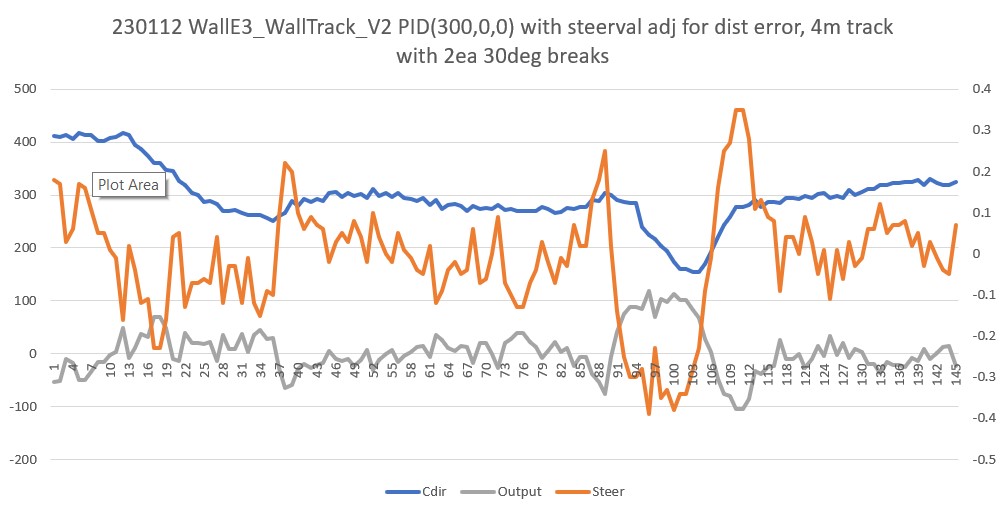
WallE3_WallTrack_V2’s tracking algorithm uses the difference between the desired and measured offset distances to ‘tweak’ the steering value, as discussed above, so clearly this works – or at least doesn’t screw things up too badly. In the above telemetry output, the ‘Steer’ column is the steering value after the offset distance adjustment shown here
|
1 2 |
//have to weight value by both angle and wall offset WallTrackSteerVal = glLeftSteeringVal + (glLidar_LeftCenter - 10 * WALL_OFFSET_TGTDIST_CM) / 1000.f; |
So at the point where the robot hit the minimum center distance of about 154mm, the steering value adjustment would be (154-400)/1000 = -0.246. The total steering value term at this point was 0.23, which means the ‘raw’ steering value was +0.016 and the offset distance error term accounted for ~97% of the total. This is good evidence that including the the distance offset term works.
My new new new plan is to focus on my October 2022 post that uses the orientation angle corrected offset distance as the input to the PID engine, and see if I can incorporate this, along with all my recent updates/bugfixes into WallE3_WallTrackTuning_V5