posted 18 March 2020
This post describes my efforts to troubleshoot an I2C communications problem between an Arduino Mega control board and a Teensy 3.2 IR beam demodulation module.
Background:
My Wall-E2 autonomous wall-following robot homes in on a modulated IR beacon to connect to a charging station. The IR beacon modulation is decoded by a dedicated Teensy 3.2 and provides left/right and combined steering values to an Arduino Mega main controller over an I2C link.
During my recent work to update the robot after some enhancements, I discovered that the main controller was no longer receiving steering information from the Teensy, even though both seemed to be operating properly. Initial efforts to troubleshoot the problem did not bear fruit, so I was forced to back up and start over from scratch.
Troubleshooting:
Initially I thought the problem was a loose connection, as the system was working before. However, I am now pretty sure that I have eliminated all the obvious culprits, so I am left with the non-obvious ones.
To start with, I resurrected an old example project to demonstrate I2C master/slave operation between two Teensy modules.
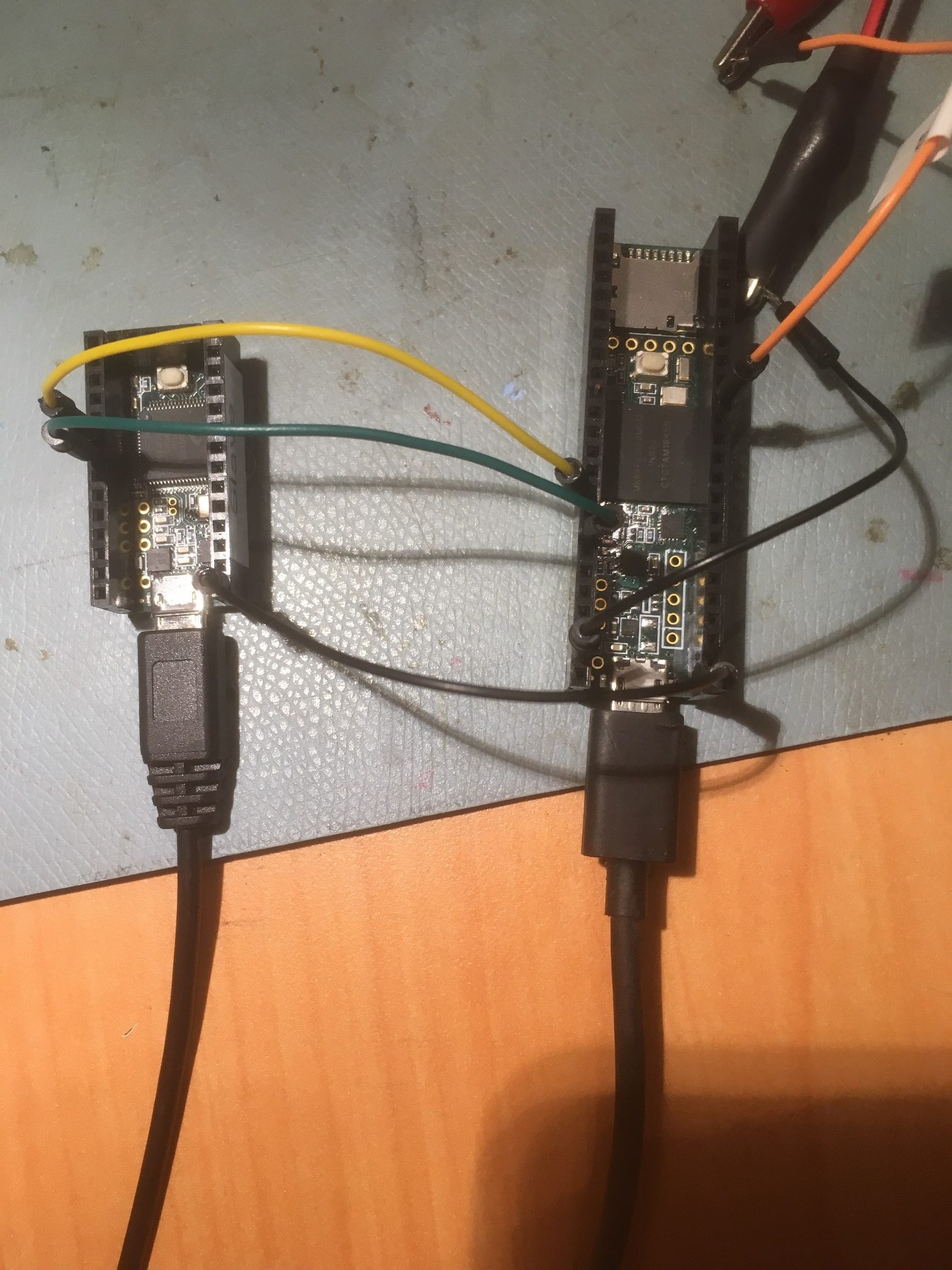
Teensy 3.2 Slave (left) and Teensy 3.5 Master (right)
Here’s the Teensy ‘Master’ code:
|
1 2 3 4 5 6 7 8 9 10 11 12 13 14 15 16 17 18 19 20 21 22 23 24 25 26 27 28 29 30 31 32 33 34 35 36 37 38 39 40 41 42 43 44 45 46 47 48 49 50 51 52 53 54 55 56 57 58 59 60 61 62 63 64 65 66 67 68 69 70 71 72 73 74 75 76 77 78 79 80 81 82 83 84 85 86 87 88 89 90 91 92 93 94 95 96 97 98 99 100 101 102 103 104 105 106 107 108 109 110 111 |
// ------------------------------------------------------------------------------------------- // Basic Master // ------------------------------------------------------------------------------------------- // // This creates a simple I2C Master device which when triggered will send/receive a text // string to/from a Slave device. It is intended to pair with a Slave device running the // basic_slave sketch. // // Pull pin12 input low to send. // Pull pin11 input low to receive. // // This example code is in the public domain. // // ------------------------------------------------------------------------------------------- #include <i2c_t3.h> #include <T3_I2C_Anything.h> // Memory #define MEM_LEN 256 char databuf[MEM_LEN]; int count; float xmtfloat = 1.2344; void setup() { pinMode(LED_BUILTIN, OUTPUT); // LED digitalWrite(LED_BUILTIN, LOW); // LED off pinMode(12, INPUT_PULLUP); // Control for Send pinMode(11, INPUT_PULLUP); // Control for Receive // Setup for Master mode, pins 18/19, external pullups, 400kHz, 200ms default timeout //Wire.begin(I2C_MASTER, 0x00, I2C_PINS_18_19, I2C_PULLUP_EXT, 400000); Wire.begin(I2C_MASTER, 0x00, I2C_PINS_18_19, I2C_PULLUP_INT, 400000); Wire.setDefaultTimeout(200000); // 200ms // Data init memset(databuf, 0, sizeof(databuf)); count = 0; //Serial.begin(115200); unsigned long now = millis(); Serial.begin(1); //rate value ignored int idx = 0; while (!Serial && (millis() - now) < 3000) { delay(500); idx++; } Serial.printf("Serial available after %lu mSec\n", millis() - now); Serial.printf("loop idx = %d\n", idx); Serial.printf("I2C_Master Example\n"); Serial.printf("\nGround Pin 12 to transmit a float value to the slave\n"); Serial.printf("\nGround Pin 11 to request a float value from the slave\n\n"); } void loop() { count++; uint8_t target = 0x66; // target Slave address //size_t idx; // Send string to Slave // if (digitalRead(12) == LOW) { digitalWrite(LED_BUILTIN, HIGH); // LED on // Transmit to Slave //Serial.printf("Sending to Slave: %3.3f\n", xmtfloat*count); float a = xmtfloat * count; Serial.printf("Sending to Slave: %3.6f (0x%x)\n", a , *(unsigned int*)&a); Wire.beginTransmission(target); // Slave address I2C_writeAnything(xmtfloat*count); Wire.endTransmission(); // Transmit to Slave // Check if error occured if (Wire.getError()) Serial.print("FAIL\n"); else Serial.print("OK\n"); digitalWrite(LED_BUILTIN, LOW); // LED off delay(100); // Delay to space out tests } // Read string from Slave if (digitalRead(11) == LOW) { digitalWrite(LED_BUILTIN, HIGH); // LED on Serial.print("Reading from Slave: ");// Print message // Read from Slave Wire.requestFrom(target, (size_t)MEM_LEN); // Read from Slave (string len unknown, request full buffer) if (Wire.getError()) Serial.print("FAIL\n"); else { float slave_val = 0; I2C_readAnything(slave_val); Serial.printf("Received %f from Slave\n", slave_val); } digitalWrite(LED_BUILTIN, LOW); // LED off delay(100); // Delay to space out tests } } |
And the Teensy ‘Slave’ code:
|
1 2 3 4 5 6 7 8 9 10 11 12 13 14 15 16 17 18 19 20 21 22 23 24 25 26 27 28 29 30 31 32 33 34 35 36 37 38 39 40 41 42 43 44 45 46 47 48 49 50 51 52 53 54 55 56 57 58 59 60 61 62 63 64 65 66 67 68 69 70 71 72 73 74 75 76 77 78 79 80 81 82 83 84 85 86 87 88 89 90 91 |
// ------------------------------------------------------------------------------------------- // Basic Slave // ------------------------------------------------------------------------------------------- // // This creates a simple I2C Slave device which will print whatever text string is sent to it. // It will retain the text string in memory and will send it back to a Master device if // requested. It is intended to pair with a Master device running the basic_master sketch. // // This example code is in the public domain. // // ------------------------------------------------------------------------------------------- /* 03/07/20 Modified to be Teensy-specific, and to use 'I2C_Anything' for I2C communications */ #include <i2c_t3.h> #include <T3_I2C_Anything.h> // Function prototypes void receiveEvent(size_t count); void requestEvent(void); // Memory volatile uint8_t received; volatile float rcvfloat = 0; // // Setup // void setup() { pinMode(LED_BUILTIN, OUTPUT); // LED // Setup for Slave mode, address 0x66, pins 18/19, internal pullups, 400kHz //Wire.begin(I2C_SLAVE, 0x66, I2C_PINS_18_19, I2C_PULLUP_INT, 400000); //Wire.begin(I2C_SLAVE, 0x66, I2C_PINS_18_19, I2C_PULLUP_INT, 100000); Wire.begin(I2C_SLAVE, 0x66, I2C_PINS_18_19, I2C_PULLUP_EXT, 100000); // register events Wire.onReceive(receiveEvent); Wire.onRequest(requestEvent); //Serial.begin(115200); unsigned long now = millis(); Serial.begin(1); //rate value ignored int idx = 0; while (!Serial && (millis() - now) < 3000) { delay(500); idx++; } Serial.printf("Serial available after %lu mSec\n", millis() - now); Serial.printf("I2C Slave Example\n"); } void loop() { // print received data - this is done in main loop to keep time spent in I2C ISR to minimum if (received) { digitalWrite(LED_BUILTIN, HIGH); Serial.printf("Slave received: %f\n", rcvfloat); received = 0; digitalWrite(LED_BUILTIN, LOW); } } // // handle Rx Event (incoming I2C data) // void receiveEvent(size_t count) { received = count; // set received flag to count, this triggers print in main loop I2C_readAnything(rcvfloat); } // // handle Tx Event (outgoing I2C data) // void requestEvent(void) { Serial.printf("Sending %f to Master\n", rcvfloat); const byte* p = (const byte*)&rcvfloat; unsigned int i; for (i = 0; i < sizeof rcvfloat; i++) Wire.write(*p++); delay(5); //experiment //I2C_writeAnything(rcvfloat); } |
With this configuration I got the following output:
Master:
|
1 2 3 4 5 6 7 8 9 10 11 12 13 14 15 16 17 |
Opening port Port open Sending to Slave: 812935680.000000 (0x4e41d1a8) OK Sending to Slave: 812935680.000000 (0x4e41d1a8) OK Sending to Slave: 812935680.000000 (0x4e41d1a8) OK Sending to Slave: 812935680.000000 (0x4e41d1a8) OK ... ... Reading from Slave: Received 812935744.000000 from Slave Reading from Slave: Received 812935744.000000 from Slave Reading from Slave: Received 812935744.000000 from Slave Reading from Slave: Received 812935744.000000 from Slave Reading from Slave: Received 812935744.000000 from Slave |
Slave:
|
1 2 3 4 5 6 7 8 9 10 11 12 |
Opening port Port open Slave received: 812935680.000000 Slave received: 812935680.000000 Slave received: 812935680.000000 Slave received: 812935680.000000 ... ... Sending 812935744.000000 to Master Sending 812935744.000000 to Master Sending 812935744.000000 to Master Sending 812935744.000000 to Master |
So this seems to be working OK.
Then I added in a third Teensy module (T3.5) running my newly developed I2C-Sniffer code, so that I could ‘sniff’ the I2C traffic between the two Teensy’s. This will give me a ‘known-good’ baseline for when I move back to the non-working Arduino Mega Master and Teensy Slave condition that is causing me problems.
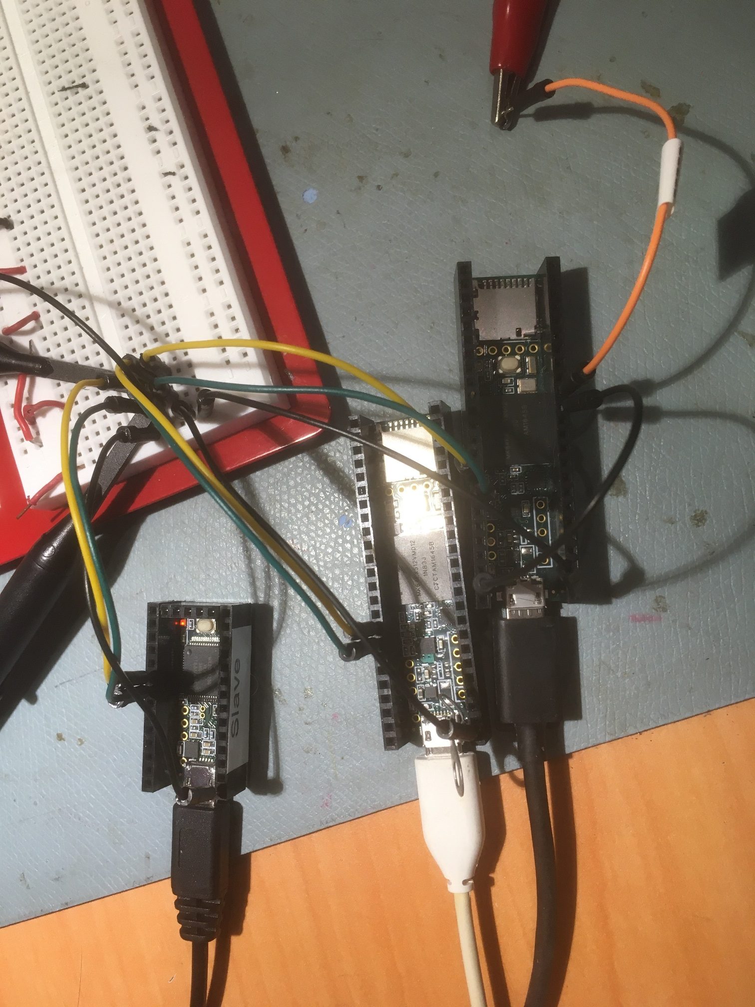
Teensy 3.2 Slave (left), Teensy 3.5 I2C Sniffer (middle), Teensy 3.5 Master (right)
Here’s the Teensy ‘Sniffer’ code:
|
1 2 3 4 5 6 7 8 9 10 11 12 13 14 15 16 17 18 19 20 21 22 23 24 25 26 27 28 29 30 31 32 33 34 35 36 37 38 39 40 41 42 43 44 45 46 47 48 49 50 51 52 53 54 55 56 57 58 59 60 61 62 63 64 65 66 67 68 69 70 71 72 73 74 75 76 77 78 79 80 81 82 83 84 85 86 87 88 89 90 91 92 93 94 95 96 97 98 99 100 101 102 103 104 105 106 107 108 109 110 111 112 113 114 115 116 117 118 119 120 121 122 123 124 125 126 127 128 129 130 131 132 133 134 135 136 137 138 139 140 141 142 143 144 145 146 147 148 149 150 151 152 153 154 155 156 157 158 159 160 161 162 163 164 165 166 167 168 169 170 171 172 173 174 175 176 177 178 179 180 181 182 183 184 185 186 187 188 189 190 191 192 193 194 195 196 197 198 199 200 201 202 203 204 205 206 207 208 209 210 211 212 213 214 215 216 217 218 219 220 221 222 223 224 225 226 227 228 229 230 231 232 233 234 235 236 237 238 239 240 241 242 243 244 245 246 247 248 249 250 251 252 253 254 255 256 257 258 259 260 261 262 263 264 265 266 267 268 269 270 271 272 273 274 275 276 277 278 279 280 281 282 283 284 285 286 287 288 289 290 291 292 293 294 295 296 297 298 299 300 301 302 303 304 305 306 307 308 309 310 311 312 313 314 315 316 317 318 319 320 321 322 323 324 325 326 327 328 329 330 331 332 333 334 335 336 337 338 339 340 341 342 343 344 345 346 347 348 349 350 351 352 353 354 355 356 357 358 359 360 361 362 363 364 365 366 367 368 369 370 371 372 373 374 375 376 377 378 379 380 381 382 383 384 385 386 387 388 389 390 391 392 393 394 395 396 397 398 399 400 401 402 403 404 405 406 407 408 409 410 411 412 413 414 415 416 417 418 419 420 421 422 423 424 425 426 427 428 429 430 431 432 433 434 435 436 437 438 439 440 441 442 443 444 445 446 447 448 449 450 451 452 453 454 455 456 457 458 459 460 461 462 463 464 465 466 467 468 469 470 471 472 473 474 475 476 477 478 479 480 481 482 483 484 485 486 487 488 489 490 491 492 493 494 495 496 497 498 499 500 501 502 503 504 505 506 507 508 509 510 511 512 513 514 515 516 517 518 519 520 521 522 523 524 525 526 527 528 529 530 531 532 533 534 535 536 537 538 539 540 541 542 543 544 545 546 547 548 549 550 551 552 553 554 555 556 557 558 559 560 561 562 563 564 565 566 567 568 569 570 571 572 573 574 575 576 577 578 579 580 581 582 583 584 585 586 587 588 589 590 591 592 593 594 595 596 597 598 599 600 601 602 603 604 605 606 607 608 609 610 611 612 613 614 615 616 617 618 619 620 621 622 623 624 625 626 627 628 629 630 631 632 633 634 635 636 637 638 639 640 641 642 643 644 645 646 647 648 649 650 651 652 653 654 655 656 657 658 659 660 661 662 663 664 665 666 667 668 669 670 671 672 673 674 675 676 677 678 679 680 681 682 683 684 685 686 687 688 689 690 691 692 693 694 695 696 697 698 699 700 701 702 703 704 705 706 707 708 709 710 711 712 713 714 715 716 717 718 719 720 721 722 723 724 725 726 727 728 729 730 731 732 733 734 735 736 737 738 739 740 741 742 743 744 745 746 747 748 749 750 751 752 753 754 755 756 757 758 759 760 761 762 763 764 765 766 767 768 769 770 771 772 |
/* Name: Teensy_I2C_Sniffer_V11.ino Created: 1/18/2020 10:55:55 AM Author: FRANKNEWXPS15\Frank */ /* 'Notes: A typical I2C sentence when communicating with a MPU6050 IMU module goes something like: "I2C(68) wrote 1 byte to 75 - C0 Done." "I2C(68) wrote 3 bytes to 72 - C0 0C 10 Done." "I2C(68) read 5 bytes from 6A - C0 0C 10 14 03 Done." To form a sentence, we need: Device addr: 68 in the above examples Read/Write direction To/From register address: 75, 72 and 6A in the above examples Data: C0, C0 0C 10, and C0 0C 10 14 03 in the above examples number of bytes written/read: 1,3 & 5 in the above examples Each I2C communication proceeds as follows (assuming a START from an IDLE condition): A START or RESTART condition, denoted by SDA & SCL HIGH, followed by SDA LOW, SCL HIGH A 7-bit device address, MSB first (0x8/0xC = 1, 0x0/0x4 = 0) A R/W bit (0x8/0xC = read, 0x0/0x4 = write) An ACK bit (0x8/0xC = NAK, 0x0/0x4 = ACK) If the bus direction is WRITE, then A register address for read/write zero or more additional data bytes Else (the bus direction is READ) One or more additional data bytes Endif This version uses a fixed-size (2048 bytes) array instead of tonton81's circular buffer library. To generalize for any I2C slave device rather than just the MPU6050 IMU, comment out the "#define MPU6050_SPECIFIC line below. This will remove all MPU6050 specific code */ //#define MPU6050_SPECIFIC #include <TimerOne.h> //needed for ISR #ifdef MPU6050_SPECIFIC #include "helper_3dmath.h" //Arduino\Libraries\i2cdevlib\Arduino\MPU6050\ needed to compute yaw from MPU6050 DMP packet #endif #define PARSE_LOOP_DEBUG const uint16_t CAPTURE_ARRAY_SIZE = 2048; const uint16_t VALID_DATA_ARRAY_SIZE = 2048; const int WAITING_PRINT_INTERVAL_MSEC = 200;//interval timer for 'Waiting for data...' printout #define MONITOR_OUT1 2 //so can monitor ISR activity with O'scope #define MONITOR_OUT2 3 //so can monitor ISR activity with O'scope #define MONITOR_OUT3 4 //so can monitor ISR activity with O'scope #define SDA_PIN 18 #define SCL_PIN 19 #pragma region PROCESSING_VARIABLES uint8_t devAddr; uint8_t regAddr; uint8_t databytes[2048]; //holds multiple databytes for later output sentence construction uint16_t numbytes = 0; //number of data bytes extracted from data stream int ACKNAKFlag; //can be negative uint16_t databyte_idx = 0; //index into databyte_array uint8_t killbuff[2]; //used to consume start/stop bytes elapsedMillis mSecSinceLastWaitingPrint; uint8_t valid_data[2048]; uint16_t numvalidbytes = 0; //number of valid bytes in this burst uint16_t read_idx = 0; //pointer to next byte pair to be processed //added for bus direction labels enum BUSDIR { WRITE, READ, UNKNOWN = -1 } RWDir; BUSDIR BusDir = BUSDIR::UNKNOWN; #pragma endregion ProcVars #pragma region ISR_SUPPORT uint8_t raw_data[CAPTURE_ARRAY_SIZE]; //holds data captured from I2C bus volatile uint16_t write_idx = 0; volatile uint8_t current_portb = 0xFF; volatile uint8_t last_portb = 0xFF; volatile uint16_t mult0xCCount = 0; const uint16_t MAX_IDLE_COUNT = 2500; volatile bool bDone = false; volatile bool bWaitingForStart = true; volatile bool bIsData = true; volatile bool bIsStart = false; volatile bool bIsStop = false; volatile uint8_t last_current; #pragma endregion ISR Support #ifdef MPU6050_SPECIFIC //01/21/20 these forward declarations are required to force the preprocessor //to handle #ifdef MPU6050_SPECIFIC properly uint8_t dmpGetQuaternion(int16_t* data, const uint8_t* packet); uint8_t dmpGetQuaternion(Quaternion* q, const uint8_t* packet); uint8_t dmpGetYawPitchRoll(float* data, Quaternion* q, VectorFloat* gravity); uint8_t dmpGetGravity(VectorFloat* v, Quaternion* q); Quaternion q; // [w, x, y, z] quaternion container VectorInt16 aa; // [x, y, z] accel sensor measurements VectorInt16 aaReal; // [x, y, z] gravity-free accel sensor measurements VectorInt16 aaWorld; // [x, y, z] world-frame accel sensor measurements VectorFloat gravity; // [x, y, z] gravity vector float ypr[3]; // [yaw, pitch, roll] yaw/pitch/roll container and gravity vector float global_yawval = 0; //updated by GetIMUHeadingDeg() #endif // MPU6050_SPECIFIC void setup() { unsigned long now = millis(); Serial.begin(1); //rate value ignored int idx = 0; while (!Serial && (millis() - now) < 3000) { delay(500); idx++; } Serial.printf("Serial available after %lu mSec\n", millis() - now); pinMode(MONITOR_OUT1, OUTPUT); digitalWrite(MONITOR_OUT1, LOW); pinMode(MONITOR_OUT2, OUTPUT); digitalWrite(MONITOR_OUT2, LOW); pinMode(MONITOR_OUT3, OUTPUT); digitalWrite(MONITOR_OUT3, LOW); pinMode(SCL_PIN, INPUT); pinMode(SDA_PIN, INPUT); //reset port byte vars & start timer last_portb = current_portb = 0; write_idx = 0; memset(raw_data, 255, CAPTURE_ARRAY_SIZE); //PrintNextArrayBytes(raw_data, 255, 20); Timer1.initialize(1); // run every mico second Timer1.attachInterrupt(capture_data); mSecSinceLastWaitingPrint = 0; } //------------------------------------------------------------------------------- //-------------------------------- ISR ------------------------------------ //------------------------------------------------------------------------------- FASTRUN void capture_data() //void capture_data() { last_portb = current_portb; current_portb = GPIOB_PDIR & 12; //reads state of SDA (18) & SCL (19) at same time if (!bDone && last_portb != current_portb) { mult0xCCount = 0; //reset IDLE counter digitalWriteFast(MONITOR_OUT1, HIGH); //01/17/20: joepasquariello suggestion last_current = (last_portb << 4) | (current_portb); bIsStart = (last_current == 0xC4); bIsStop = (last_current == 0x4C); bIsData = (last_current == 0x04) || (last_current == 0x8C); if (bIsStart) //START { digitalWriteFast(MONITOR_OUT2, HIGH); if (bWaitingForStart) { digitalWriteFast(MONITOR_OUT3, HIGH); //start of entire capture bWaitingForStart = false; } } else if (bIsStop) //STOP { digitalWriteFast(MONITOR_OUT2, LOW); } if (!bWaitingForStart && (bIsData || bIsStart || bIsStop)) { //digitalWriteFast(MONITOR_OUT3, HIGH); raw_data[write_idx] = last_portb; write_idx++; raw_data[write_idx] = current_portb; write_idx++; if (write_idx >= CAPTURE_ARRAY_SIZE) { bDone = true; digitalWriteFast(MONITOR_OUT3, LOW); } } digitalWriteFast(MONITOR_OUT1, LOW); } else if (!bDone && mult0xCCount < MAX_IDLE_COUNT && last_portb == 0xc && current_portb == 0xc) { mult0xCCount++; if (mult0xCCount >= MAX_IDLE_COUNT) { digitalWriteFast(MONITOR_OUT3, LOW); bDone = true; } } } //------------------------------------------------------------------------------- //-------------------------------- END ISR --------------------------------- //------------------------------------------------------------------------------- void loop() { if (bDone) { if (write_idx > 14) { //OK, we have some data to process. IDLE detection must have been EOM Timer1.stop(); unsigned long startMsec = millis(); //Serial.printf("%lu\t %d\t", millis(), write_idx); //PrintNextArrayBytes(raw_data, 0, 50); //Serial.printf(" - %lu\n", millis()); uint16_t numprocessed = DecodeAndPrintValidData(raw_data); //decode and print everything captured so far unsigned long endMsec = millis(); Serial.printf("%lu: processed = %d elements in %lu mSec\n\n", startMsec, numprocessed, endMsec-startMsec); Timer1.start(); } read_idx = 0; bDone = false; mult0xCCount = 0; write_idx = 0; bWaitingForStart = true; } else { //no data to process, but don't blow prints out every mSec... if (mSecSinceLastWaitingPrint > WAITING_PRINT_INTERVAL_MSEC) { mSecSinceLastWaitingPrint -= WAITING_PRINT_INTERVAL_MSEC; Serial.printf("%lu: Waiting for Data...\n", millis()); } } } void PrintNextArrayBytes(uint8_t* data, uint16_t startidx, uint16_t numbytes) { Serial.printf("%d bytes starting at %d: ", numbytes, startidx); for (uint16_t i = 0; i < numbytes; i++) { Serial.printf("%x ", data[i + startidx]); } } uint16_t DecodeAndPrintValidData(byte* data) { //Purpose: decode and print I2C conversation held in raw_data array //Inputs: // cb = 2048 element FIFO //Outputs: // returns number of bytes processed, or -1 for failure // outputs structured I2C sentence to serial monitor //Plan: // Step1: Cull out invalid bytes // Step2: Determine if there is anything to do (have to have more than one transition in FIFO) // Step3: Parse transitions into I2C sentence structure // Step4: Output sentence to serial monitor memset(valid_data, 0, VALID_DATA_ARRAY_SIZE); #ifdef PARSE_LOOP_DEBUG PrintNextArrayBytes(valid_data, 0, 20); //print out first 20 bytes for verification #endif numvalidbytes = RemoveInvalidBytes(raw_data, valid_data); #ifdef PARSE_LOOP_DEBUG Serial.printf("Removed %d invalid bytes, leaving %d remaining\n", write_idx + 1 - numvalidbytes, numvalidbytes); PrintNextArrayBytes(valid_data, 0, numvalidbytes); //print out first 20 bytes of valid_data array #endif if (numvalidbytes < 2) { return 0; } while (read_idx < numvalidbytes) { #ifdef PARSE_LOOP_DEBUG Serial.printf("At top of while (read_idx < numvalidbytes): read_idx = %d\n", read_idx); Serial.printf("Next two bytes in valid_data are %x, %x\n", valid_data[read_idx], valid_data[read_idx + 1]); #endif //Find a START sequence (0xC followed by 0x4) while (!IsStart(valid_data, read_idx) && read_idx < numvalidbytes) { //Serial.printf("looking for start...\n"); read_idx++; } //at this point, read_idx should point to next valid byte pair #ifdef PARSE_LOOP_DEBUG Serial.printf("Start sequence found at %d\n", read_idx - 2); //PrintNextFIFOBytes(valid_data, 20); #endif if (numvalidbytes - read_idx > 14)//14 entries required for 7-bit address { //Get 7-bit device address devAddr = Get7BitDeviceAddr(valid_data, read_idx); #ifdef PARSE_LOOP_DEBUG Serial.printf("devAddr = %x\n", devAddr); #endif } else { #ifdef PARSE_LOOP_DEBUG Serial.printf("ran out of data at readidx = %d - exiting!\n", read_idx); #endif break; } //get read/write flag 1 = Read, 0 = Write, -1 = error BusDir = (BUSDIR)GetReadWriteFlag(valid_data, read_idx); #ifdef PARSE_LOOP_DEBUG Serial.printf("BusDir = %s\n", ((BusDir == BUSDIR::WRITE) ? "WRITE" : "READ")); //PrintNextFIFOBytes(valid_data, 20); #endif //get ACK/NAK flag ACKNAKFlag = GetACKNAKFlag(valid_data, read_idx); numbytes = GetDataBytes(valid_data, read_idx, databytes); //terminates on a START, but the start bytes are not consumed #ifdef PARSE_LOOP_DEBUG Serial.printf("Got %d bytes from GetDataBytes() --> ", numbytes); for (size_t i = 0; i < numbytes; i++) { Serial.printf(" %x ", databytes[i]); } Serial.printf("\n"); //PrintNextFIFOBytes(cb_trans, 20); #endif //If the bus direction is WRITE, then extract // A register address for read / write // zero or more additional data bytes if (BusDir == BUSDIR::WRITE) { regAddr = databytes[0]; #ifdef PARSE_LOOP_DEBUG Serial.printf("regAddr = %x, read_idx = %d\n", regAddr, read_idx); #endif //check for additional data if (numbytes > 1) { #ifdef PARSE_LOOP_DEBUG Serial.printf("Additional data found!\n"); for (size_t i = 0; i < numbytes; i++) { Serial.printf("data[%d] = %x\n", i, databytes[i]); } #endif //1st byte is register addr, subsequent bytes are data OutputFormattedSentence(BusDir, devAddr, regAddr, numbytes, databytes, 1); } } else //all bytes are data { #ifdef PARSE_LOOP_DEBUG Serial.printf("In data block: got %d bytes of data\n", numbytes); for (size_t i = 0; i < numbytes; i++) { Serial.printf("data[%d] = %x\n", i, databytes[i]); } #endif OutputFormattedSentence(BusDir, devAddr, regAddr, numbytes, databytes, 0); } #ifdef PARSE_LOOP_DEBUG Serial.printf("At end of while (read_idx < numvalidbytes): read_idx = %d\n", read_idx); #endif }//while (read_idx < numvalidbytes) return numvalidbytes; } #pragma region Support Functions bool IsStart(byte* data, uint16_t& readidx) { bool result = false; //Serial.printf("IsStart[%d] = %x, IsStart[%d] = %x\n", // readidx, data[readidx], readidx + 1, data[readidx + 1]); if (data[readidx] == 0xC && data[readidx + 1] == 0x4) { result = true; readidx += 2; //bump to next byte pair } return result; } bool IsStop(byte* data, uint16_t& readidx) { bool result = false; //Serial.printf("IsStop[%d] = %x, IsStop[%d] = %x\n", //readidx, data[readidx], readidx + 1, data[readidx + 1]); if (data[readidx] == 0x4 && data[readidx + 1] == 0xC) { result = true; readidx += 2; //bump to next byte pair } return result; } uint8_t Get7BitDeviceAddr(byte* data, uint16_t& readidx) { //Purpose: Construct a 7-bit address starting from dataidx //Inputs: // data = pointer to valid data array // readidx = starting index of 7-bit address sequence (MSB first) //Outputs: // returns the address as an 8-bit value with the MSB = 0, or 0x0 if unsuccessful // dataidx = pointer to next data entry //Plan: // Step1: Convert a pair of data entries into a 0 or 1 // Step2: Add the appropriate value to an ongoing sum // Step3: return the total. //Notes: // A '0' is coded as a 0x0 followed by a 0x4 // A '1' is coded as a 0x8 followed by a 0xC uint8_t devAddr = 0x0; //failure return value //Serial.printf("Get7BitDeviceAddr: readidx = %d\n",readidx); //devAddr is exactly 7 bits long, so 8 bits with MSB = 0 for (size_t i = 0; i < 7; i++) { if (data[readidx] == 0x0 && data[readidx + 1] == 0x4) { readidx += 2; //advance the pointer, but don't add to sum } else if (data[readidx] == 0x8 && data[readidx + 1] == 0xC) { //Serial.printf("Get7BitDeviceAddr: '1' found at i = %d, adding %x to devAddr to get %x\n", // i, 1 << (7 - i), devAddr + (1 << (7-i))); readidx += 2; //advance the pointer devAddr += (1 << (7 - i)); //add 2^(7-i) to sum } } devAddr = devAddr >> 1; //divide result by 2 to get 7-bit addr from 8 bits return devAddr; } int Get8BitDataByte(byte* data, uint16_t& readidx) { //Purpose: Construct a 8-bit data byte starting from dataidx //Inputs: // data = pointer to valid data array // readidx = starting index of 8-bit data byte (MSB first) //Outputs: // returns the address as an 8-bit value, or 0x0 if unsuccessful // dataidx = pointer to next data entry //Plan: // Step1: Convert a pair of data entries into a 0 or 1 // Step2: Add the appropriate value to an ongoing sum // Step3: return the total. //Notes: // A '0' is coded as a 0x0 followed by a 0x4 // A '1' is coded as a 0x8 followed by a 0xC // 12/29/19 - changed return val to int, so can return -1 when a 'short byte' is detected int dataval = 0x0; //failure return value #ifdef GET_8BIT_DATABYTE_DEBUG Serial.printf("Get8BitDataByte: data[%d] = %x, data[%d] = %x\n", readidx, data[readidx], readidx + 1, data[readidx + 1]); #endif //8 bits with MSB = 0 int numbytes = 0; for (size_t i = 0; i < 8; i++) { if (data[readidx] == 0x0 && data[readidx + 1] == 0x4) { readidx += 2; //advance the pointer, but don't add to sum numbytes++; } else if (data[readidx] == 0x8 && data[readidx + 1] == 0xC) { #ifdef GET_8BIT_DATABYTE_DEBUG Serial.printf("Get8BitDataByte: '1' found at i = %d, adding %x to devAddr to get %x\n", i, 1 << (7 - i), dataval + (1 << (7 - i))); #endif readidx += 2; //advance the pointer dataval += (1 << (7 - i)); //add 2^(8-i) to sum numbytes++; } } #ifdef GET_8BIT_DATABYTE_DEBUG Serial.printf("Get8BitDataByte: numbytes = %d\n", numbytes); #endif if (numbytes != 8) { dataval = -1; //error return value } return dataval; } int GetReadWriteFlag(byte* data, uint16_t& readidx) { //Purpose: decode R/W byte pair //Inputs: // data = pointer to valid data array // readidx = index into data to start of R/W byte pair //Outputs: // readidx = if successful, points to next byte pair in data // returns 1 for Read (0x8/0xC), 0 for Write (0x0/0x4), -1 for failure //Notes: // //Serial.printf("GetReadWriteFlag: readidx = %d, data[readidx] = %x, data[readidx+1]= %x\n", // readidx, data[readidx], data[readidx + 1]); int result = 0; if (data[readidx] == 0x8 && data[readidx + 1] == 0xC) { result = 1; //read detected readidx += 2; //point to next byte pair } else if (data[readidx] == 0x0 && data[readidx + 1] == 0x4) { result = 0; //write detected readidx += 2; //point to next byte pair } else { result = -1; //failed to detect read or write } return result; } int GetACKNAKFlag(byte* data, uint16_t& readidx) { //Purpose: decode ACK/NAK byte pair //Inputs: // data = pointer to valid data array // readidx = index into data to start of ACK/NAK byte pair //Outputs: // readidx = if successful, points to next byte pair in data // returns 1 for NAK (0x8/0xC), 0 for ACK (0x0/0x4), -1 for failure //Notes: // //Serial.printf("GetACKNAKFlag: readidx = %d, data[readidx] = %x, data[readidx+1]= %x\n", // readidx, data[readidx], data[readidx + 1]); int result = 0; if (data[readidx] == 0x8 && data[readidx + 1] == 0xC) { result = 1; //NAK detected readidx += 2; //point to next byte pair } else if (data[readidx] == 0x0 && data[readidx + 1] == 0x4) { result = 0; //ACK detected readidx += 2; //point to next byte pair } else { result = -1; //failed to detect ACK or NAK } return result; } int GetDataBytes(uint8_t* data, uint16_t& readidx, uint8_t* databytes) { //Notes: // 01/01/2020: removed databyteidx from sig - always starts at zero uint16_t numbytes = 0; uint16_t databyte_idx = 0; bool StartFlag = false; bool StopFlag = false; do { int dataval = Get8BitDataByte(data, readidx); //watch out for 'short byte' reads if (dataval >= 0) { uint8_t databyte = (uint8_t)dataval; databytes[databyte_idx] = databyte; databyte_idx++; numbytes++; } ACKNAKFlag = GetACKNAKFlag(data, readidx); StartFlag = IsStart(data, readidx); StopFlag = IsStop(data, readidx); #ifdef PARSE_LOOP_DEBUG Serial.printf("IsStart returned %d, IsStop returned %d, dataidx = %d\n", StartFlag, StopFlag, readidx); #endif } while (!StartFlag && !StopFlag && readidx < numvalidbytes); readidx -= 2;//back readidx up so loop top is positioned correctly. return numbytes; } void OutputFormattedSentence(int RW, uint8_t dev, uint8_t reg, uint8_t numbytes, uint8_t* bytearray, uint16_t startidx) { Serial.printf("%lu I2C(%x) %s %d bytes %s %x... ", millis(), dev, (RW == 0 ? "writing" : "reading"), numbytes - startidx, (RW == 0 ? "to" : "from"), reg); //for (size_t i = startidx; i < numbytes; i++) //{ // Serial.printf("%x ", bytearray[i]); //} //Serial.printf(". Done\n"); #ifdef MPU6050_SPECIFIC //01/18/20 experiment to decode 28-byte packet into yaw value if (numbytes == 28) { dmpGetQuaternion(&q, bytearray); dmpGetGravity(&gravity, &q); dmpGetYawPitchRoll(ypr, &q, &gravity); //compute the yaw value global_yawval = ypr[0] * 180 / M_PI; Serial.printf("yawval = %3.2f\n", global_yawval); } else { Serial.printf(". Done\n"); } #endif // MPU6050_SPECIFIC } uint16_t RemoveInvalidBytes(uint8_t* rawdata, uint8_t* validdata) { uint16_t numvalid = 0; uint16_t valididx = 0; //Serial.printf("raw data array contains %d bytes\n", write_idx + 1); //PrintNextArrayBytes(raw_data, 0, 20); //OK, now go back through the array, excising invalid sequences for (uint16_t rawidx = 0; rawidx < write_idx;/*rawidx incremented internally*/) { uint8_t firstByte = raw_data[rawidx]; //get the first byte uint8_t secondByte = raw_data[rawidx + 1]; //get the next byte bool validpair = ( (firstByte == 0xC && secondByte == 0x4) //START or RESTART || (firstByte == 0x4 && secondByte == 0xC) //STOP || (firstByte == 0x0 && secondByte == 0x4) //0 OR ACK || (firstByte == 0x8 && secondByte == 0xC) //1 or NAK ); //Serial.printf("rawidx %d: Considering %x and %x: validity = %d\n", //rawidx, firstByte, secondByte, validpair); if (validpair) { //save valid bytes to valid_bytes array validdata[valididx] = firstByte; validdata[valididx + 1] = secondByte; numvalid += 2; //Serial.printf("Added %x & %x at idx = %d & %d\n", firstByte, secondByte, valididx, valididx + 1); //PrintNextArrayBytes(validdata,0,numvalid); rawidx += 2; valididx += 2; } else { rawidx++; //on invalid, just go to next byte } } return numvalid; } #pragma endregion Support Functions #ifdef MPU6050_SPECIFIC //#pragma region YAW_COMPUTATIONS ////01/18/2020: I copied these functions from MPU6050_6Axis_MotionApps_V6_12.h and //// modified them to be called directly instead of from an 'mpu' object // uint8_t dmpGetQuaternion(int16_t* data, const uint8_t* packet) { // TODO: accommodate different arrangements of sent data (ONLY default supported now) if (packet != 0) { data[0] = ((packet[0] << 8) | packet[1]); data[1] = ((packet[4] << 8) | packet[5]); data[2] = ((packet[8] << 8) | packet[9]); data[3] = ((packet[12] << 8) | packet[13]); } return 0; } uint8_t dmpGetQuaternion(Quaternion* q, const uint8_t* packet) { // TODO: accommodate different arrangements of sent data (ONLY default supported now) int16_t qI[4]{ 0,0,0,0 }; uint8_t status = dmpGetQuaternion(qI, packet); if (status == 0) { q->w = (float)qI[0] / 16384.0f; q->x = (float)qI[1] / 16384.0f; q->y = (float)qI[2] / 16384.0f; q->z = (float)qI[3] / 16384.0f; return 0; } return status; // int16 return value, indicates error if this line is reached } uint8_t dmpGetYawPitchRoll(float* data, Quaternion* q, VectorFloat* gravity) { // yaw: (about Z axis) data[0] = atan2(2 * q->x * q->y - 2 * q->w * q->z, 2 * q->w * q->w + 2 * q->x * q->x - 1); // pitch: (nose up/down, about Y axis) data[1] = atan2(gravity->x, sqrt(gravity->y * gravity->y + gravity->z * gravity->z)); // roll: (tilt left/right, about X axis) data[2] = atan2(gravity->y, gravity->z); if (gravity->z < 0) { if (data[1] > 0) { data[1] = PI - data[1]; } else { data[1] = -PI - data[1]; } } return 0; } uint8_t dmpGetGravity(VectorFloat* v, Quaternion* q) { v->x = 2 * (q->x * q->z - q->w * q->y); v->y = 2 * (q->w * q->x + q->y * q->z); v->z = q->w * q->w - q->x * q->x - q->y * q->y + q->z * q->z; return 0; } //#pragma endregion YAW_COMPUTATIONS #endif //MPU6050_SPECIFIC |
With this setup with the master sending data to the slave, I got the following outputs:
Master
|
1 2 3 4 5 6 7 8 9 10 11 12 13 14 15 16 17 18 19 20 21 22 23 24 25 26 27 28 29 30 |
Sending to Slave: 1048.005615 (0x4483002e) i = 0: I2C_WriteAnything() sending 2E i = 1: I2C_WriteAnything() sending 0 i = 2: I2C_WriteAnything() sending 83 i = 3: I2C_WriteAnything() sending 44 OK Sending to Slave: 1049.239990 (0x448327ae) i = 0: I2C_WriteAnything() sending AE i = 1: I2C_WriteAnything() sending 27 i = 2: I2C_WriteAnything() sending 83 i = 3: I2C_WriteAnything() sending 44 OK Sending to Slave: 1050.474487 (0x44834f2f) i = 0: I2C_WriteAnything() sending 2F i = 1: I2C_WriteAnything() sending 4F i = 2: I2C_WriteAnything() sending 83 i = 3: I2C_WriteAnything() sending 44 OK Sending to Slave: 1051.708862 (0x448376af) i = 0: I2C_WriteAnything() sending AF i = 1: I2C_WriteAnything() sending 76 i = 2: I2C_WriteAnything() sending 83 i = 3: I2C_WriteAnything() sending 44 OK Sending to Slave: 1052.943237 (0x44839e2f) i = 0: I2C_WriteAnything() sending 2F i = 1: I2C_WriteAnything() sending 9E i = 2: I2C_WriteAnything() sending 83 i = 3: I2C_WriteAnything() sending 44 OK |
Slave:
|
1 2 3 4 5 |
Slave received: 1048.005615 Slave received: 1049.239990 Slave received: 1050.474487 Slave received: 1051.708862 Slave received: 1052.943237 |
I2C Sniffer:
|
1 2 3 4 5 6 7 8 9 10 11 12 13 14 15 16 17 18 19 20 |
Start sequence found at 0 devAddr = 66 BusDir = WRITE Got 4 bytes from GetDataBytes() --> 2e 0 83 44 Start sequence found at 0 devAddr = 66 BusDir = WRITE Got 4 bytes from GetDataBytes() --> ae 27 83 44 Start sequence found at 0 devAddr = 66 BusDir = WRITE Got 4 bytes from GetDataBytes() --> 2f 4f 83 44 Start sequence found at 0 devAddr = 66 BusDir = WRITE Got 4 bytes from GetDataBytes() --> af 76 83 44 Start sequence found at 0 devAddr = 66 BusDir = WRITE Got 4 bytes from GetDataBytes() --> 2f 9e 83 44 |
In the other direction, with the slave sending data to the master, I got the following:
Slave:
|
1 2 3 4 |
Sending 28398426.000000 to Master Sending 28398426.000000 to Master Sending 28398426.000000 to Master Sending 28398426.000000 to Master |
Master:
|
1 2 3 |
Reading from Slave: Received 28398426.000000 from Slave Reading from Slave: Received 28398426.000000 from Slave Reading from Slave: Received 28398426.000000 from Slave |
I2C Sniffer:
|
1 2 3 4 5 6 7 8 9 10 11 12 13 14 15 16 17 18 19 20 21 22 23 |
In data block: got 112 bytes of data data[0] = ad data[1] = a9 data[2] = d8 data[3] = 4b data[4] = 0 data[5] = 0 .... In data block: got 112 bytes of data data[0] = ad data[1] = a9 data[2] = d8 data[3] = 4b data[4] = 0 data[5] = 0 ..... In data block: got 112 bytes of data data[0] = ad data[1] = a9 data[2] = d8 data[3] = 4b data[4] = 0 data[5] = 0 |
Where the HEX sequence 4B D8 A9 AD converted to a IEEE float = 2.83984e+07
So, the Teensy-to-Teensy I2C connection is clearly working in both directions, and the Teensy I2C Sniffer is successfully capturing and decoding the I2C traffic between the two modules – cool!
So, the next step is to replace the ‘Master’ Teensy with an Arduino Mega and repeat the process. Hopefully this will allow me to figure out why the slave-to-master data transfer isn’t working
21 March 2020 Update:
Based on the above results, I formed a hypothesis that the problem with sending I2C data from a Teensy slave to an Arduino Mega master might be due to the Mega not being able to properly interpret 0-3.3V transitions from the Teensy. So, I decided to construct a low-to-high level converter to make sure that SDA data from the Teensy was presented to the Mega as 0-5V transitions rather than the Teensy’s ‘raw’ 0-3.3V ones. To do this I used the circuit shown below, except with a 1K instead of 10K resistor for R2 to clean up the transitions at 100KHz.
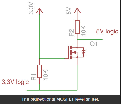
Bidirectional 3.3-5V level shifter using 2N7000 MosFet
Here’s a scope photo of the 3.3V input to and the 5V output from the 2N7000-based level shifter. The top trace is the Teensy 0-3.3V output, and the bottom trace is the 0-5V level-shifted version. Both traces are 1V/cm, and the horizontal time scale is 20 uSec/cm.
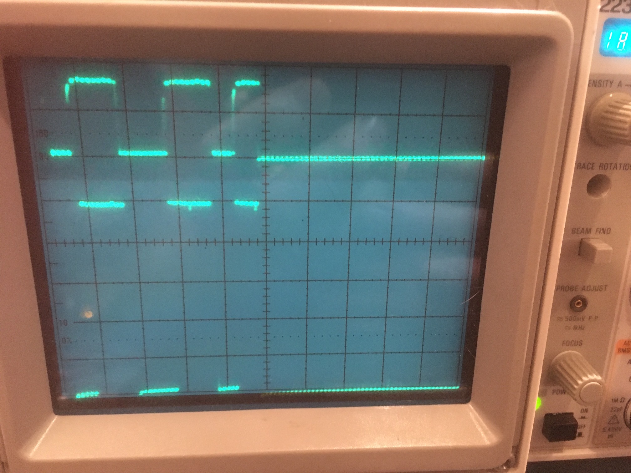
Teensy slave, Mega master: Top: 0-3.3V input. Bottom: 0-5V output. Both traces are 1V/cm vertical, 20 uSec cm horizontally
To verify that the above circuit worked properly, I used it in the SDA line (the SCL line doesn’t require any level shifting as it is from the 5V Mega to the 3.3V Teensy) with a Teensy slave and a Teensy master. This is OK, as Teensy 3.x’s can handle 5V inputs, and it worked properly in both directions. Here’s a shot of the SDA line
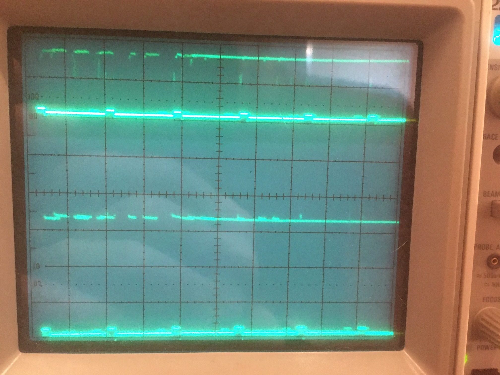
Teensy slave, Teensy master: Top: 0-3.3V input. Bottom: 0-5V output. Both traces are 1V/cm vertical, 20 uSec cm horizontally
However, after replacing the Teensy master with the Mega one, I had the same problem as before – I can successfully transfer data from Mega master to Teensy slave, but not in the other direction. There is still a problem somewhere, and I no longer think it’s due to level-shifting problems. From the above scope photos, it is clear that only a few bytes are transmitted by the Teensy slave each time it services the OnRequest() interrupt, while that same function transmits MUCH more data when servicing the same request from the Teensy 3.5 master.
Stay tuned!
23 March 2020 Update:
OK, back to the basics: I downloaded the code for a very basic Arduino-Arduino I2C tutorial, and verified that it worked OK. I also took a scope shot of SDA/SCL activity during the two-way data transfers, as shown below:
Basic Arduino-Arduino tutorial layout
I2C line activity for the ‘Basic Arduino – Arduino I2C Tutorial’
So now that I have a working baseline for the Arduino-Arduino I2C case, I plan to incrementally modify it toward duplicating the non-working Arduino-Arduino I2C case until it breaks, and then I’ll know that the last incremental modification is the culprit. At the moment, I’m leaning toward the use of the I2CDev & SBWIRE libraries as they are the only significant difference between the working and non-working setups. We’ll see….
24 March 2020 Update:
I created a new Arduino project called ‘I2C_Master_Tut_Mod1’ initially identical to ‘I2C_Master_Tutorial’ and verified that it worked properly with the unmodified ‘I2C_Slave_Tutorial’ project, and then started modifying it.
- Added #include <PrintEx.h> //allows printf-style printout syntax
StreamEx mySerial = Serial; //added 03/18/18 for printf-style printing, and changed all occurrences of ‘Serial’ to ‘mySerial’ and modified print statements to ‘printf’ format. All worked fine. - Added #include <I2C_Anything.h> and changed loop() to write a float value to the slave. However, this caused a compile error. When I started tracking it down I realized that I had previously modified ‘I2C_Anything.h’ to #include SBWIRE.h rather than the original #include Wire.h. So, this could be the culprit, assuming that there is something about SBWIRE that causes Arduino I2C slaves to misbehave.
- Copied I2C_Anything.h/cpp from the Libraries folder to my new ‘I2C_Master_Tut_Mod1’ folder, and un-modified it to reference back Wire.h vs SBWIRE.h.
25 March 2020 Update:
As it turns out, I was never able to get the ‘I2C_Master_Tut_Mod1’ project working with #include <I2C_Anything.h> , no matter what I did, including copying the #include <I2C_Anything.h> to the local folder and including it as a resource int the VS2019 project, build cleans, removing the _vm folder created by Visual Micro, etc. To make it even stranger, I created a new Arduino project in VS2019 called ‘I2C_Master_Tut_Mod2’, copied the ‘I2C_Anything.h’ file to the local folder, and it compiles without error! So now I have two almost completely identical Arduino projects, one of which compiles fine and the other of which blows a bunch of errors about twi.c. I’m currently working with Tim Leek at VisualMicro to sort out what I did wrong.
27 March 2020 Update:
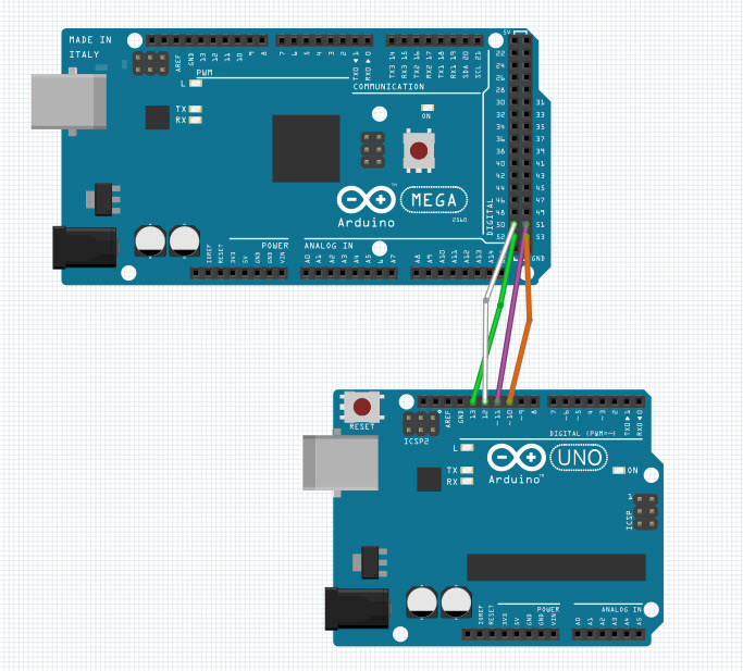
Ok, I now have the Arduino Mega master to Arduino Uno slave setup working, with I2C_Anything. I can transfer a float value in either direction with no problem. The master and slave code sets and the corresponding outputs are shown below.
Master Sketch:
|
1 2 3 4 5 6 7 8 9 10 11 12 13 14 15 16 17 18 19 20 21 22 23 24 25 26 27 28 29 30 31 32 33 34 35 36 37 38 39 40 41 42 43 44 45 46 47 48 49 50 51 52 53 54 55 56 57 58 59 60 61 62 63 64 65 66 67 68 69 70 71 72 73 74 75 76 77 78 |
/* Name: I2C_Master_Tut_Mod2.ino Created: 3/25/2020 8:54:55 AM Author: FRANKNEWXPS15\Frank */ /* Name: I2C_Master_Tutorial.ino Created: 3/23/2020 1:20:08 PM Author: FRANKNEWXPS15\Frank */ /* I2C Master Demo i2c-master-demo.ino Demonstrate use of I2C bus Master sends character and gets reply from Slave DroneBot Workshop 2019 https://dronebotworkshop.com */ // Include Arduino Wire library for I2C #include <Wire.h> #include "PrintEx.h" #include "I2C_Anything.h" // Define Slave I2C Address #define SLAVE_ADDR 9 StreamEx mySerial = Serial; //added 03/18/18 for printf-style printing // Define Slave answer size #define ANSWERSIZE 5 const float sendval = 3.14159f; float rcvval = 0; void setup() { // Initialize I2C communications as Master Wire.begin(); // Setup serial monitor Serial.begin(115200); Serial.println("I2C Master Demonstration"); } void loop() { delay(50); //Serial.println("Write data to slave"); mySerial.printf("Sent %3.5f: ",sendval); // Write a charatre to the Slave Wire.beginTransmission(SLAVE_ADDR); //Wire.write(0); I2C_writeAnything(sendval); Wire.endTransmission(); //Serial.println("Receive data"); //// Read response from Slave //// Read back 5 characters //Wire.requestFrom(SLAVE_ADDR, ANSWERSIZE); //// Add characters to string //String response = ""; //while (Wire.available()) { // char b = Wire.read(); // response += b; //} //// Print to Serial Monitor //Serial.println(response); //03/26/2020 gfp rev to retrieve float value Wire.requestFrom(SLAVE_ADDR, sizeof(float)); I2C_readAnything(rcvval); mySerial.printf("Received %4.1f\n",rcvval); } |
Slave Sketch:
|
1 2 3 4 5 6 7 8 9 10 11 12 13 14 15 16 17 18 19 20 21 22 23 24 25 26 27 28 29 30 31 32 33 34 35 36 37 38 39 40 41 42 43 44 45 46 47 48 49 50 51 52 53 54 55 56 57 58 59 60 61 62 63 64 65 66 67 68 69 70 71 72 73 74 75 76 77 78 79 80 81 82 83 84 85 86 87 88 89 90 91 92 93 94 95 |
/* Name: I2C_Slave_Tutorial.ino Created: 3/23/2020 1:23:40 PM Author: FRANKNEWXPS15\Frank */ /* I2C Slave Demo i2c-slave-demo.ino Demonstrate use of I2C bus Slave receives character from Master and responds DroneBot Workshop 2019 https://dronebotworkshop.com */ // Include Arduino Wire library for I2C #include <Wire.h> #include "PrintEx.h" StreamEx mySerial = Serial; //added 03/18/18 for printf-style printing //03/26/2020 experiment with I2C_Anything #include "I2C_Anything.h" float rcvval = 0; float sendval = 95141.3; //3.14159 written backwards // Define Slave I2C Address #define SLAVE_ADDR 9 // Define Slave answer size #define ANSWERSIZE 5 // Define string with response to Master String answer = "Hello"; void setup() { // Initialize I2C communications as Slave Wire.begin(SLAVE_ADDR); // Function to run when data requested from master Wire.onRequest(requestEvent); // Function to run when data received from master Wire.onReceive(receiveEvent); // Setup Serial Monitor Serial.begin(115200); Serial.println("I2C Slave Demonstration"); } void receiveEvent() { //Serial.println("Receive event"); // Read while data received //while (0 < Wire.available()) { // byte x = Wire.read(); //} //03/26/2020 experiment with I2C_Anything I2C_readAnything(rcvval); // Print to Serial Monitor //Serial.print("Received "); Serial.print(rcvval, 6); Serial.println(" From Master"); mySerial.printf("Received %3.6f: ", rcvval); } void requestEvent() { //// Setup byte variable in the correct size //byte response[ANSWERSIZE]; //// Format answer as array //for (byte i = 0; i < ANSWERSIZE; i++) { // response[i] = (byte)answer.charAt(i); //} //// Send response back to Master //Wire.write(response, sizeof(response)); //// Print to Serial Monitor //Serial.println("Request event"); //03/26/2020 experiment with I2C_Anything //Serial.print("Sending "); Serial.print(sendval, 6); Serial.println(" to Master"); mySerial.printf("Sent %6.1f\n",sendval); I2C_writeAnything(sendval); } void loop() { // Time delay in loop delay(50); } |
Master & Slave Output:
|
1 2 3 4 5 6 7 8 9 10 11 12 13 14 15 16 17 18 19 20 |
Opening port Port open I2C Master Demonstration Sent 3.14159: Received 95141.3 Sent 3.14159: Received 95141.3 Sent 3.14159: Received 95141.3 Sent 3.14159: Received 95141.3 Sent 3.14159: Received 95141.3 Sent 3.14159: Received 95141.3 Opening port Port open I2C Slave Demonstration Received 3.141590: Sent 95141.3 Received 3.141590: Sent 95141.3 Received 3.141590: Sent 95141.3 Received 3.141590: Sent 95141.3 Received 3.141590: Sent 95141.3 Received 3.141590: Sent 95141.3 |
So now I have a working Arduino-Arduino I2C master/slave setup, using I2C_Anything.h to transfer float values back and forth, and a working Teensy-Teensy I2C master/slave setup, using I2C_Anything.h to transfer float values back and forth.
The next step was to replace the Arduino Uno I2C slave with the Teensy 3.2 I2C slave and see if I can get that combination working. This turned out to be surprisingly easy – basically plug-and-pray (oops, I meant ‘play’).
Now that I have a simple Arduiono Mega Master – Teensy 3.2 Slave setup working, I can start to explore why my 4WD robot setup doesn’t work. Some possibilities:
- It could be that the SBWire version of the Wire library has some hidden bugs in the slave-related code. The SBWire library eliminates the well-known and well-hated ‘hang’ bug in the Arduino wire library.
- It could be that some other library I am using, like the RTC library or the Adafruit FRAM library is interfering with the Arduino-Teensy interrupts needed for master-slave communication.
- It could be that the IR demod program running on the slave Teensy is somehow interfering with master-slave communications (this is very unlikely as this same program had been working flawlessly for several months).
- Something else…
To start with, I copied the current ‘I2C_Master_Tut2’ VS2019 project to a new one – ‘I2C_Master_Tut3’ before making any modifications. I plan to keep a ‘breadcrumb trail’ of incrementally modified projects so that I can go backwards in case I get lost at some point (and, in my fairly long 50+ years as a practicing engineer, I have learned that ‘getting lost’ is part and parcel of any non-trivial troubleshooting project).
Once I verified that ‘Tut3’ properly communicated with the Teensy slave, I started making modifications.
- Replaced #include <Wire.h> with #include SBWire.h. This failed in compile with a linker error, but succeeded after I did a ‘Build -> Clean’. After uploading the new ‘Tut3’ version to the Mega, I found that master-slave communications still worked properly. This is actually a welcome development, as that now eliminates SBWire as the culprit for lost Mega-Teensy I2C capability on the robot.
- Replaced ‘#include “SBWire” with #include “MPU6050_6Axis_MotionApps_V6_12.h” and include “I2Cdev.h” (this includes SBWire.h). These two libraries are required for interfacing to the MPU6050 IMU module.
29 March 2020 Update:
So I created a new copy of the I2C master, ‘I2C_Master_Tut4’ and started adding things from the original non-working robot program.
- Added all the remaining #include’s. Still works fine with the Teensy 3.2 slave
- Added all the #defines. Still works fine
- Added all the IRHOMING parameters. OK
- Added all ENUMs, Battery constants, distance measurement support constants & array declarations, motor parameters, wheel direction constants and variables, and heading based turn parameters. No problem
- Added pin assignments. No problem.
- Added all the other pre-setup stuff. No problem
- Added ‘ Serial1.begin(9600); //03/04/16 bugfix’. This isn’t actually used anymore in the robot project, but it is there, so it could be the culprit. Nope – master/slave comms still OK.
- Added RTC initialization and support function. Still no problem
- Added FRAM initialization. No problem.
- Added MPU6050 initialization. No problem
- Added PID distance array and incremental variance initialization. No problem
- Added I/O pin initialization. No problem
- Added the rest of Setup(), and all the support functions required for the POST check to run. Compiles and runs fine. Of course, no peripherals are attached, so not much happens.
At this point I have all the pre-setup and setup code incorporated into the master/slave example, and everything is still happily plugging away. So obviously the culprit hasn’t yet been identified. However, before going any farther, I think I’ll drop ‘Tut4’ into the safe-deposit box and create a ‘Tut5’ to continue on into the loop() function.
OK, so I have a ‘Tut5’ project now, with everything up to loop() incorporated from the ‘FourWD_WallE2_V2’ robot project. Now the question is, ‘What next?’. I need to figure out what is causing I2C comms between the Mega master and the Teensy 3.2 slave to fail, so I need a way to faithfully replicate/simulate/emulate the actual robot code for this function.
The current robot algorithm as pertaining to the Teensy IR Demod module
- Each time through the loop, the current operating mode is determined.
- If IsIRBeamAvail() returns TRUE, the IR HOMING mode is activated
- IsIRBeamAvail() gets three float values from the Teensy 3.2, and returns TRUE if the total of the first two values (Fin1 & Fin2) is above a set threshold. It is this function that is failing to communicate with the Teensy. More specifically, it is this function that is not successfully acquiring the three float values, and subsequently always returns FALSE.
- If IsIRBeamAvail() returns TRUE, the IR HOMING mode is activated
So, it may be that all I have to do is to call IsIRBeamAvail() by itself, and modify the slave code to send back three floats as expected. If this works, then I’ll have to start suspecting the robot’s Teensy or the I2C wiring, or something else entirely.
2 April 2020 Update:
After some additional fumbling around with I2C_Anything and the PrintEx library printf() formats, I now have a working ‘IsIRBeamAvail()’ function in ‘Tut5’, as follows:
|
1 2 3 4 5 6 7 8 9 10 11 12 13 14 15 16 17 18 19 20 21 22 23 24 25 26 27 28 29 30 |
bool IsIRBeamAvail() { //Purpose: Determine whether or not an IR beam is available for homing //Inputs: call from loop() //Outputs: true if an IR beam is detected, false otherwise //Plan: // Step1: Get analog levels from all 4 IR detectors // Step2: return true if any of the 4 show detection level //Notes: // Might need some hysteresis here to avoid toggling in and out of the TRACKING_IRBEAM mode // 02/21/17 read each det 3 times. If any sum is less than 3 X threshold, return true. Otherwise return false // 10/15/17 rewritten to use info from IR Demod Module //get latest info from IR Demod Module long Fin1 = 0; //03/30/20 needs to be 'long int' (4 bytes) here to match Teensy int (4 bytes) long Fin2 = 23; //03/30/20 needs to be 'long int' (4 bytes) here to match Teensy int (4 bytes) float SteeringValue; mySerial.printf("\n<<<<<<< In IsIRBeamAvail() >>>>>>>>>>>>>>>>>>>>\n\n"); Wire.requestFrom(SLAVE_ADDR, sizeof(Fin1) + sizeof(Fin2)+ sizeof(SteeringValue)); I2C_readAnything(Fin1); I2C_readAnything(Fin2); I2C_readAnything(SteeringValue); mySerial.printf("Fin1 = %ld, Fin2 = %ld, SteeringValue = %3.2f\n", Fin1, Fin2, SteeringValue); return false; } |
Which, when connected to my basic Teensy 3.2 I2C slave program produces the following (correct) output:
|
1 2 3 4 5 6 7 8 9 10 11 |
<<<<<<< In IsIRBeamAvail() >>>>>>>>>>>>>>>>>>>> Fin1 = 469, Fin2 = 938, SteeringValue = 1473.41 <<<<<<< In IsIRBeamAvail() >>>>>>>>>>>>>>>>>>>> Fin1 = 470, Fin2 = 940, SteeringValue = 1476.55 <<<<<<< In IsIRBeamAvail() >>>>>>>>>>>>>>>>>>>> Fin1 = 471, Fin2 = 942, SteeringValue = 1479.69 |
At this point we have a working robot code emulation that communicates successfully with a basic Teensy 3.2 slave. So, the available culprits have been reduced significantly to
- Something about the Teensy IR demod code
- The I2C Wiring
- A hardware problem at either the robot’s Mega controller or the robot’s Teensy 3.2 controller
- Something else.
For the next step, I modified the Teensy IR Demod code to emulate the IR detector response and loaded this code into the Teensy 3.2 slave connected to the Mega master. After some initial mis-steps, it started working nicely, with the following (correct) output from the Mega master:
|
1 2 3 4 5 6 7 8 9 10 11 12 13 |
<<<<<<< In IsIRBeamAvail() >>>>>>>>>>>>>>>>>>>> Fin1 = 6400, Fin2 = 3200, SteeringValue = 0.33 <<<<<<< In IsIRBeamAvail() >>>>>>>>>>>>>>>>>>>> Fin1 = 6400, Fin2 = 3200, SteeringValue = 0.33 <<<<<<< In IsIRBeamAvail() >>>>>>>>>>>>>>>>>>>> Fin1 = 6400, Fin2 = 3200, SteeringValue = 0.33 Port closed |
So this eliminates the ‘Something about the Teensy IR demod code’ possibility from the above list.
Next, I replaced the direct SCL/SDA jumpers with the daisy-chain wiring from the robot, and miracle of miracles, I2C comms failed – YAY!!. Now hopefully I can figure out (and fix) the problem.
- First, I un-replaced the daisy-chain wiring to confirm that I2C comms were still working, and they were.
- Unplugged the daisy-chain from the FRAM, 6050IMU, and RTC modules – now working OK
- Plugged back in to FRAM unit (now have FRAM and Teensy 3.2 in chain)- – still OK
- Plugged back in to 6050 IMU (now have IMU, FRAM, and Teensy 3.2 in chain)- failed
- Plugged back in to RTC (now have RTC, FRAM, and Teensy 3.2 in chain)- failed
3 April 2020 Update:
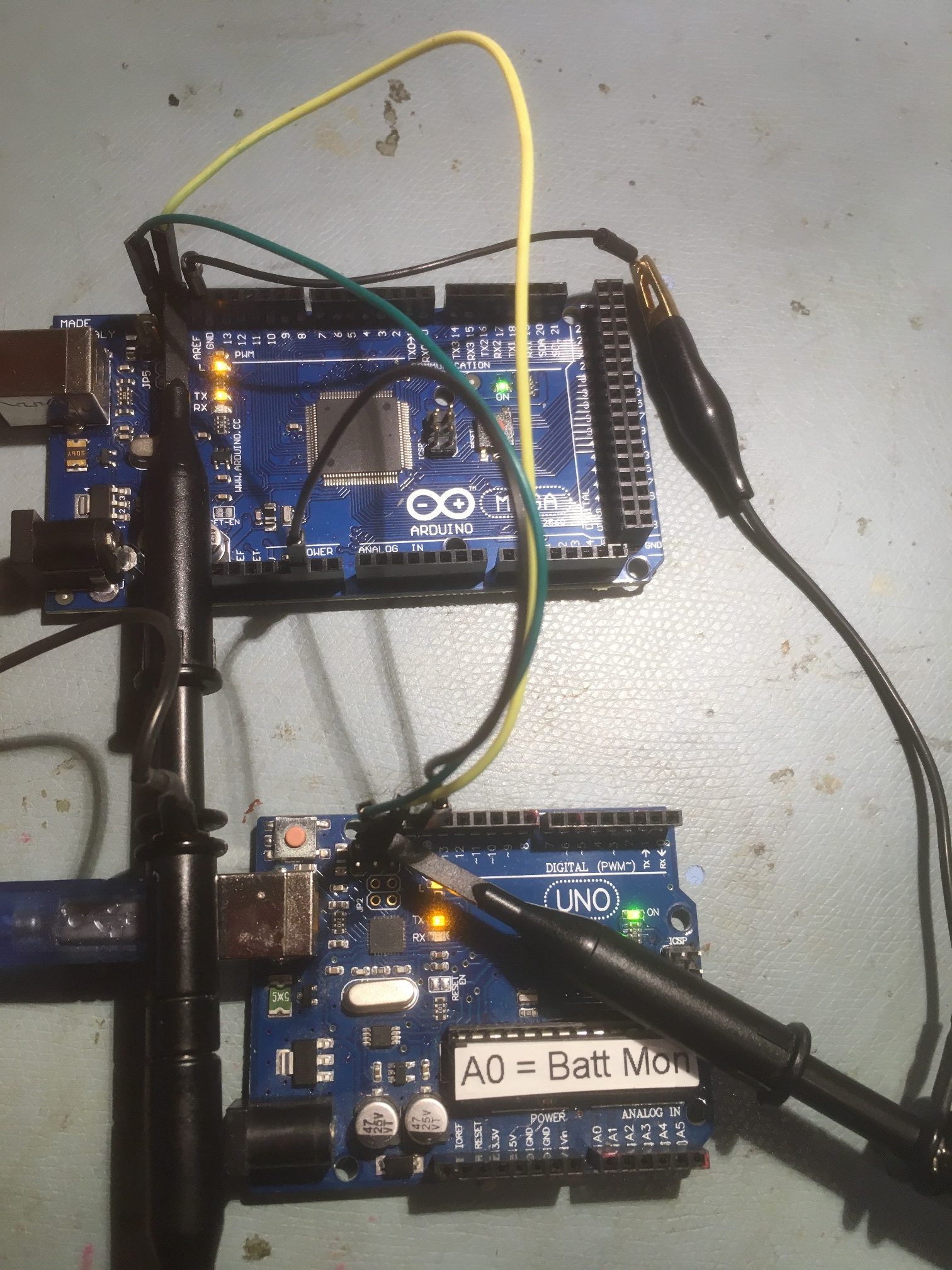
The next step in the saga was to load the ‘Tut5’ code onto the robot’s Mega 2560 controller, with the slave code still running on the original (off-robot) Teensy 3.2. Setting things up in this fashion allowed the sensors to receive power from the robot’s Mega controller as in normal operation.
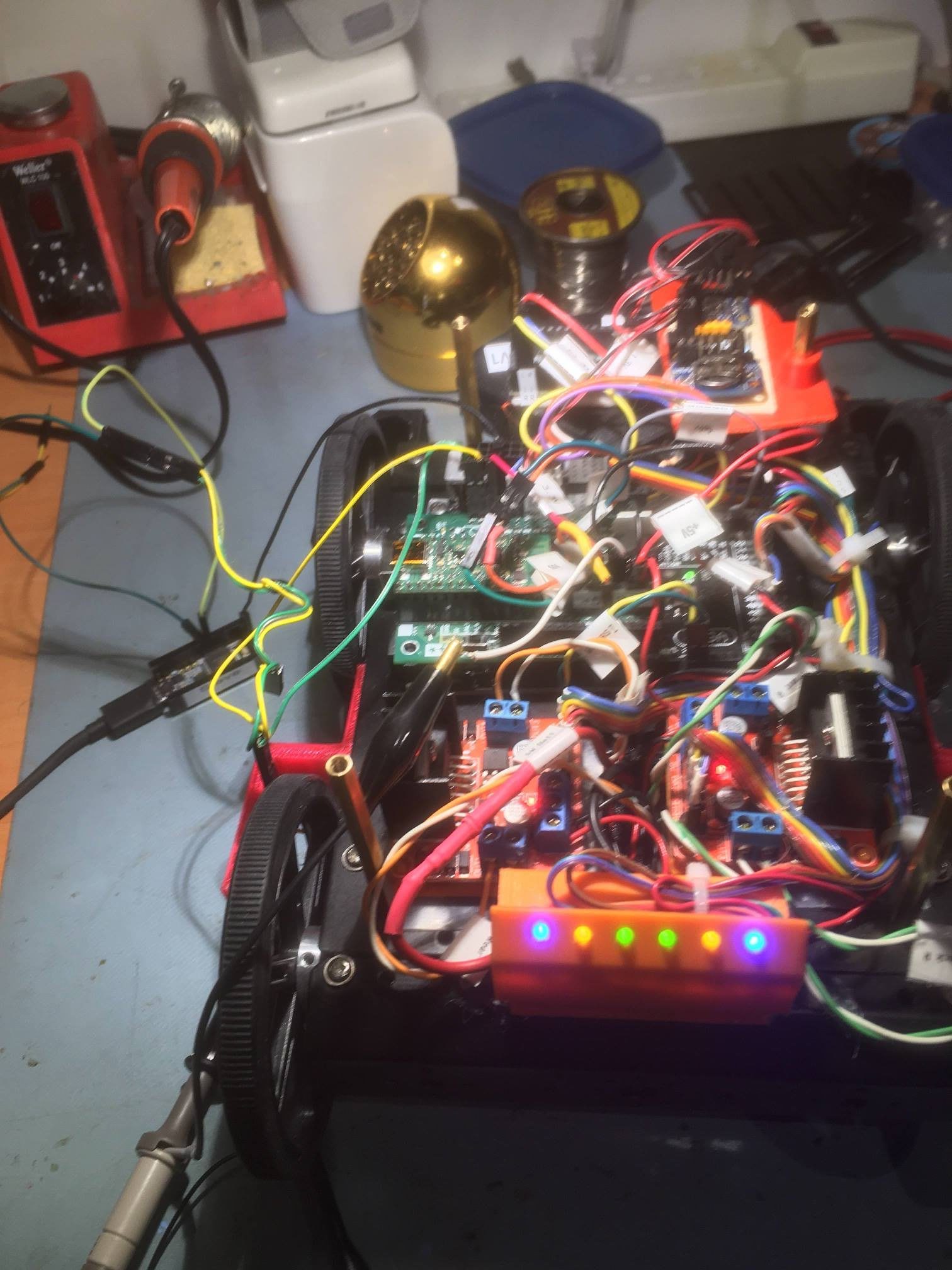
In the photo above, the Teensy 3.2 slave is shown to the left of the robot. The I2C ‘daisy-chain’ cable starts at the Mega controller (just to the right of the front left wheel), and goes through three ‘hops’ to the Teensy. With this setup, the I2C comms code still ran fine, with direct I2C jumper wires or with the daisy-chain wiring setup (with no connections to the other I2C sensors) as shown above.
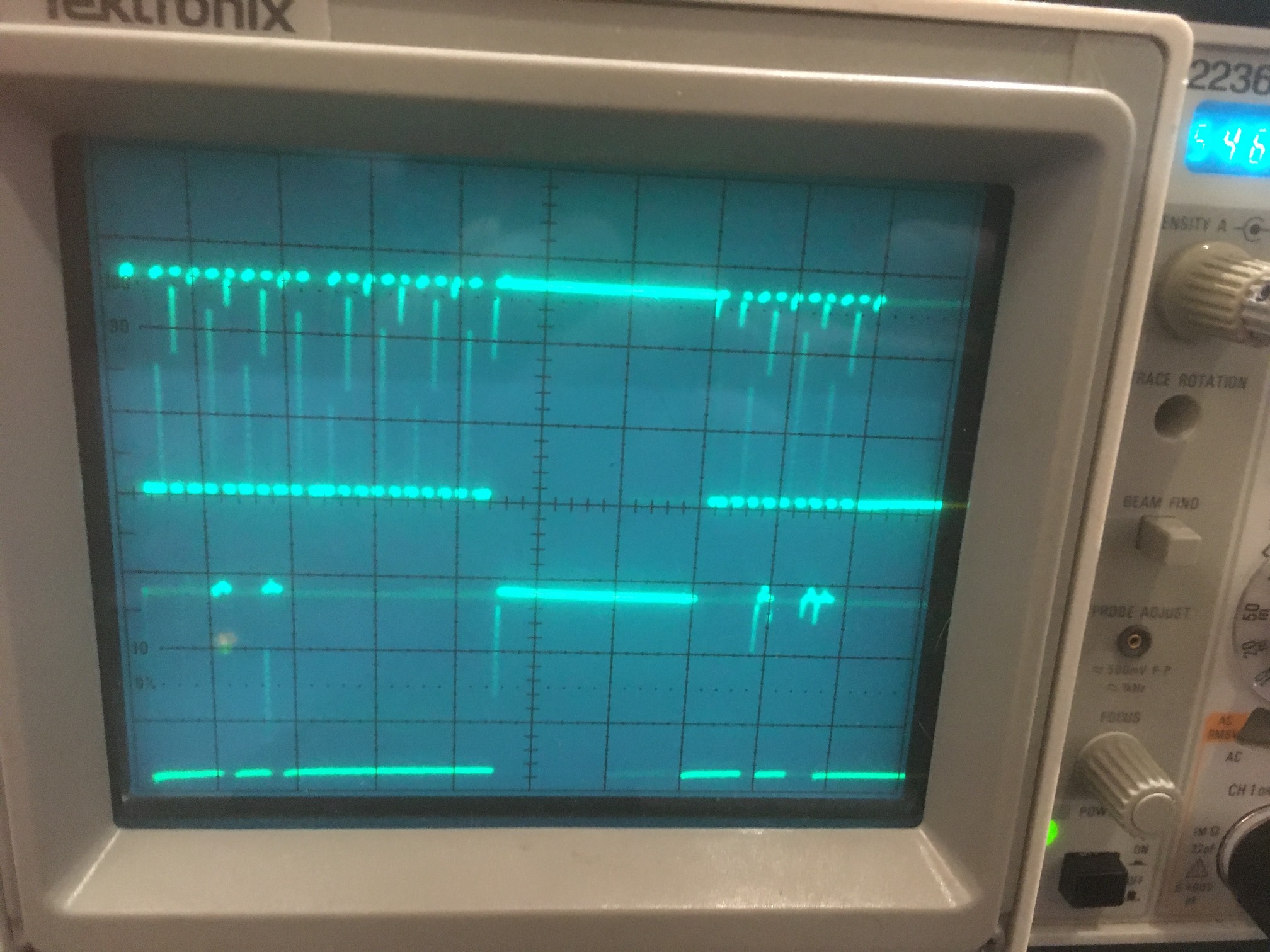
The next step was to connect the robot’s Mega controller to the robot’s Teensy 3.2 running the unmodified IR Demodulation code, with the I2C daisy-chain cable, but without anything else connected. This actually worked! So now I have a working robot system again, so something about the connections with the other sensors must be killing the I2C link to the Teensy. Here’s a scope photo of the SDA line showing the data activity. The vertical scale is 1V/cm, showing the HIGH value is about 3.8V, so the Mega must be comfortable with that value as a HIGH logic level
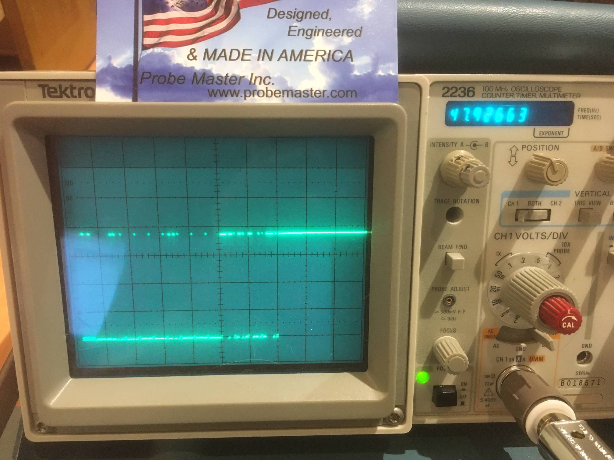
In the above photo, notice the business card for Probe Master, Inc (www.probemaster.com). These folks were kind enough to replace my ten year old scope probe with a new upgraded version at no cost – thank you Probe Master!
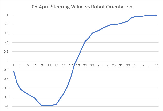
At this point I have the ‘Tut5’ program running on the Mega, and the unmodified IR Demod code running on the robot’s Teensy 3.2, and the Mega appears to be acquiring valid demod data from the Teensy. To further validate the data, I fired up my charging station with it’s square-wave modulated IR beam, and was pleased to see that the acquired data from the Teensy varied appropriately as I manually rotated the robot, as shown in the following Excel chart.
So, after all this work, the whole thing came down to a bad I2C ‘daisy-chain’ cable. This particular cable has been on the robot for a while, and was the soldering graduation exercise of my grandson Danny when he was here a couple of summers ago. It wasn’t the best job I’ve ever seen, but it was pretty good for a 15 year old ;-). In any case, I took the opportunity to build a new cable with smaller diameter wire so things would fit a little bit better into the Pololu pins, sockets, and 2-pin header sleeves as shown in the following photo.
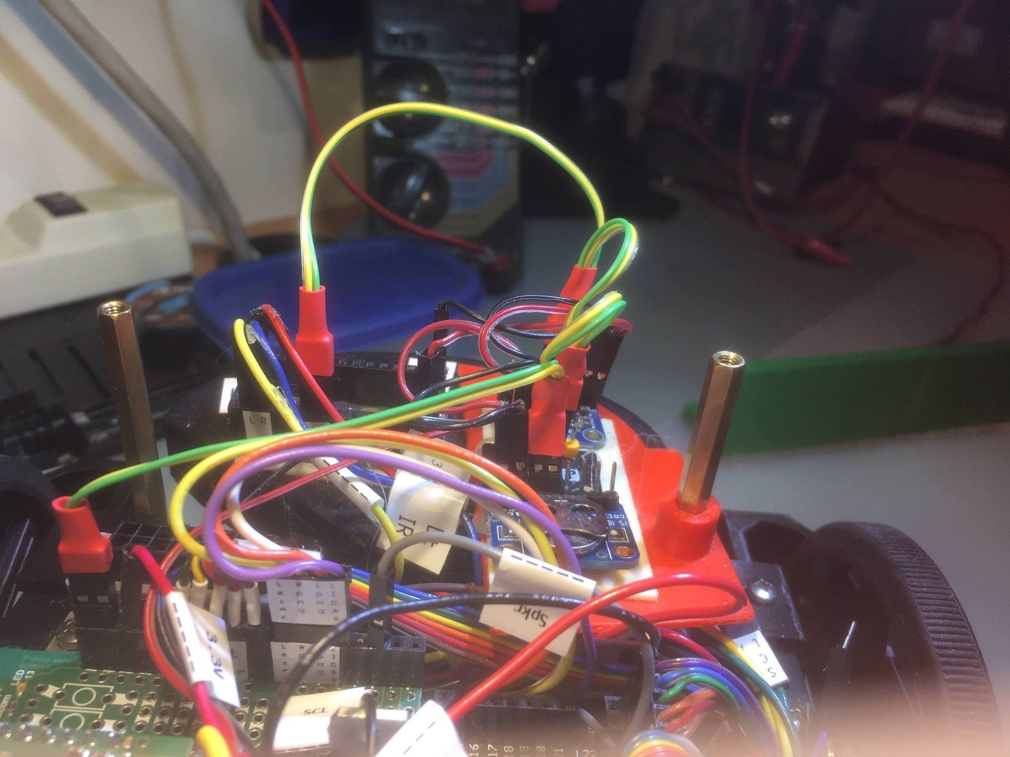
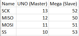
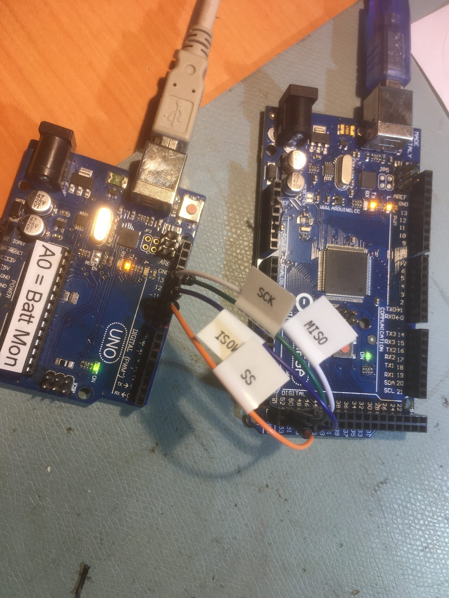
New I2C ‘daisy-chain’ cable. Run starts from the Mega connector at bottom left, then to the RTC, IMU and FRAM modules in that order, then last to the Teensy 3.2 IR Demod module.
05 April 2020 Epilogue:
Well, there was one last ‘gotcha’ in all this. When I loaded the original ‘FourWD-WallE2_V2.ino’ program back onto the Mega, it still refused to acquire valid data from the Teensy IR Demod module. So, I compared the ‘Tut5’ code to the ‘_V2’ code, and noticed three significant differences:
- In the ‘_V2’ code, the ‘Fin1/2’ variables had at some time been changed from ‘long’ to ‘int’. While this sounds reasonable, it isn’t – because a Teensy ‘int’ is 4 bytes – the same as a Mega ‘long’.
- In the ‘_V2’ code, the Wire.requestFrom() call asks for 32 bytes, but the Teensy only sends 12.
- In the ‘_V2’ code there is a loop that waits for either a timeout or receiving an entire 32-byte buffer from the Teensy. Apparently the Teensy (and/or the Mega) is slow enough so that Wire.Available() never reports a non-zero buffer size, so the loop times out.
Replacing the line
|
1 |
uint8_t numbytes = Wire.requestFrom(slaveAddr, (size_t)32); //this works, with Wire.Available() reporting 32 |
with the line
|
1 |
Wire.requestFrom(slaveAddr, sizeof(Fin1) + sizeof(Fin2) + sizeof(SteeringValue)); |
did the trick, but I have no idea why.
Replacing the debug printout lines
|
1 2 3 4 5 |
Serial.print("in IsIRBeamAvail(): got "); Serial.print(Fin1); Serial.print(", "); Serial.print(Fin2); Serial.print(", total = "); //Serial.print(SteeringValue); Serial.println(" from slave"); Serial.println(total); |
with the line
|
1 |
mySerial.printf("Fin1 = %ld, Fin2 = %ld, SteeringValue = %3.2f\n", Fin1, Fin2, SteeringValue); |
Produced lines like this one from the ‘_V2’ program
|
1 2 |
Fin1 = 390556, Fin2 = 153386, SteeringValue = 0.44 IR Beam Detected with Battery Voltage = 7.32DateTime Batt FinVal1 |
Which appear to be the correct values for the given robot orientation with respect to the charging station.
With no other changed except removing power from the charging station, the output became
|
1 2 3 4 |
Fin1 = 14, Fin2 = 28, SteeringValue = -0.33 Fin1 = 66, Fin2 = 42, SteeringValue = 0.22 Fin1 = 26, Fin2 = 48, SteeringValue = -0.30 Fin1 = 54, Fin2 = 30, SteeringValue = 0.29 |
showing definitively that the ‘_V2’ program correctly identified and decoded the square-wave modulated IR beam.
So, after a two-week off-road trip to I2C comms hell and back, I think I finally have that particular issue put to bed. It wasn’t exactly what I wanted to do, but it was at least interesting, and more important – consumed a lot of coronavirus quarantine time ;-).
Stay tuned!
Frank