Posted 20 May 2020
In a recent post, I described the issue I had discovered with the HC-SR04 ultrasonic ‘Ping’ distance sensors – namely that they don’t provide reliable distance information for off-perpendicular orientations, making them unusable for determining when Wall-E2, my autonomous wall-following robot, is oriented parallel to the nearest wall.
In the same post, I described my discovery of the STMicroelectronics VL53L0X infrared laser ‘Time-of-Flight’ distance sensor, and the thought that this might be a replacement for the HC-SR04. After running some basic experiments with one device, I became convinced that I should be able to use an array of three sensors oriented at 30 degree angles to each other to provide an accurate relative orientation to a nearby wall.
So, this post is intended to document my attempt to integrate two 3-sensor arrays into Wall-E2, starting with just the right side. If the initial results look promising, then I’ll add them to the left side as well.
Physical layout:
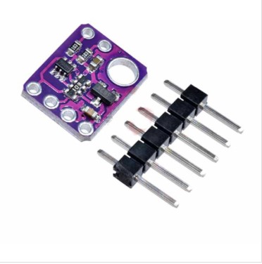
The VL53L0X sensors can be found in several different packages. The one I’m trying to use is the GY530/VL53L0X module available from multiple vendors. Here’s a shot from eBay
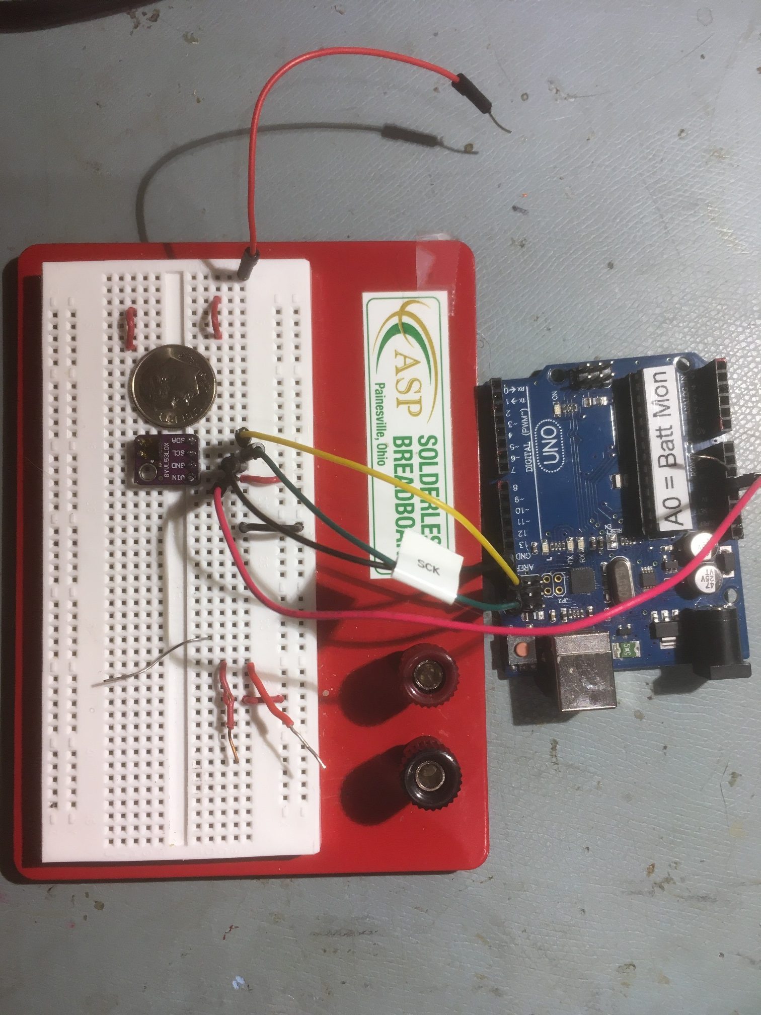
GY530/VL53L0X test setup with Arduino. Note size relative to U.S. Dime coin
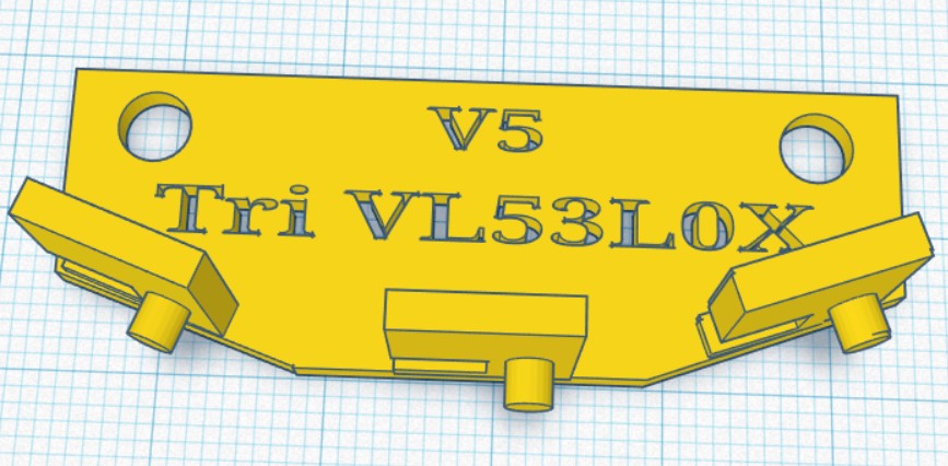
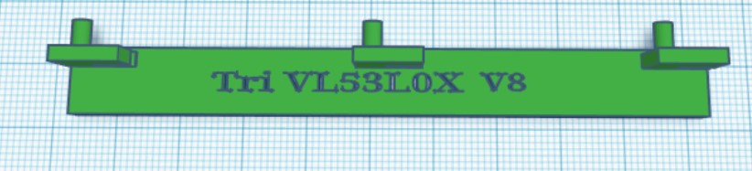
The basic idea is to mount three of the above sensors in an array oriented to cover about 60 degrees. So, I designed and printed a bracket that would fit in the same place as the HC-SR04 ‘ping’ sensor, as shown below:
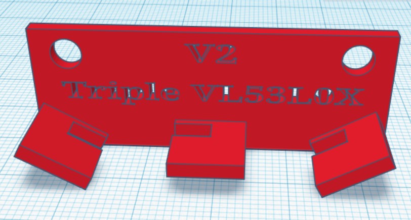
TinkerCad design for triple sensor mounting bracket
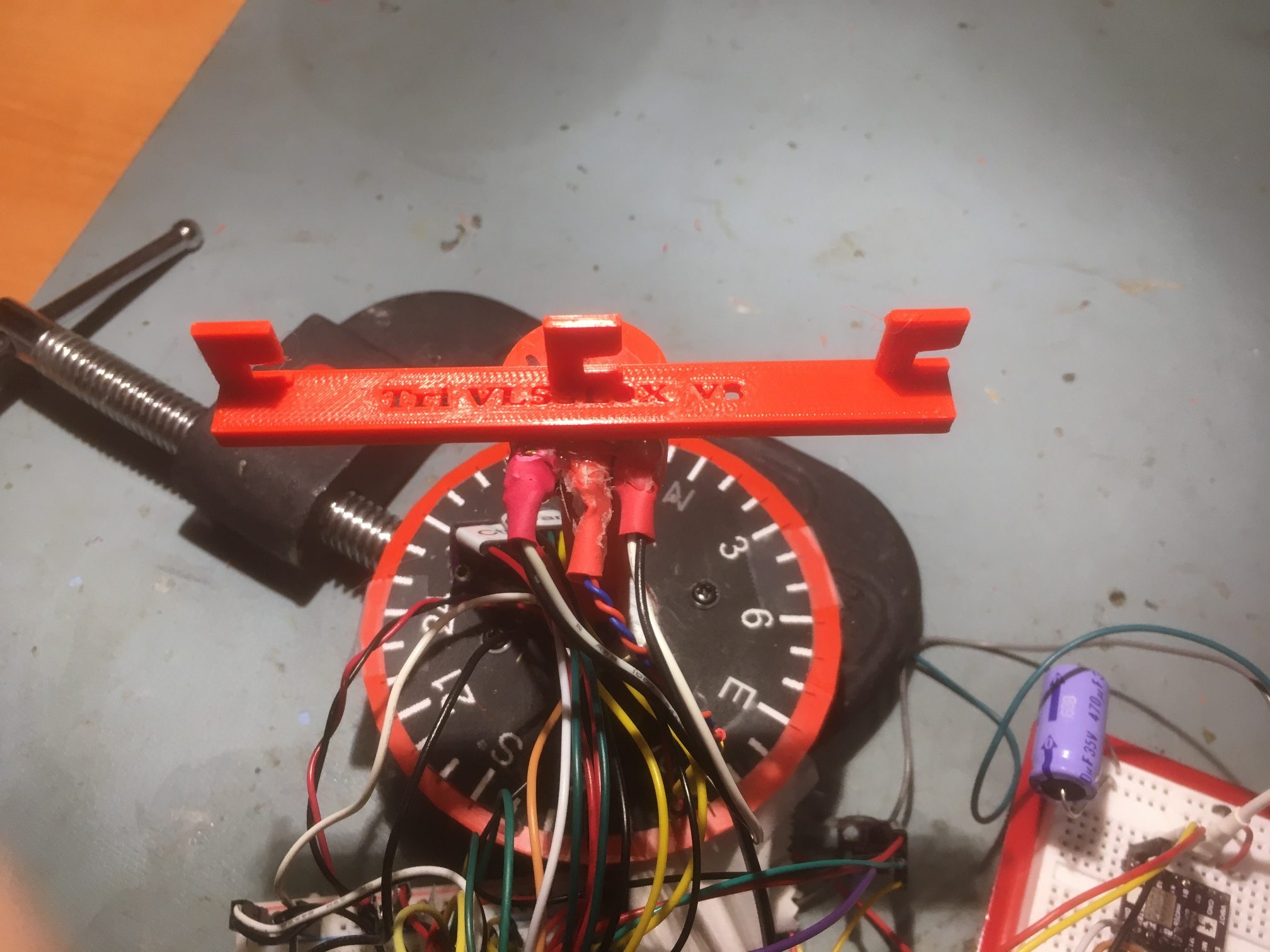
And here is the finished bracket with the center sensor installed (I haven’t received the others yet)
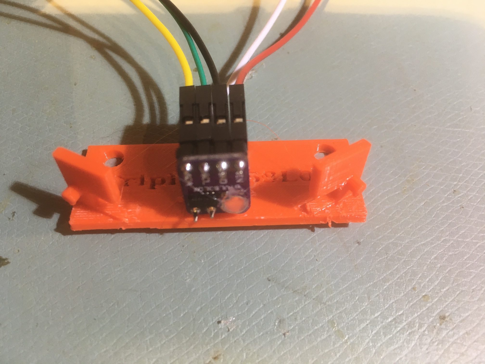
VL53L0X module mounted at the center position on triple-sensor bracket
System Integration:
The VL53L0X chip has a default I2C address of 0x29. While this address can be changed in software to allow multiple V53L0X modules to be used, the chips don’t remember the last address used, and so must be reprogrammed at startup each time. The procedure requires the use of the chip’s XSHUT input, which means that a digital I/O line must be dedicated to each of the six modules planned for this configuration, in addition to the power, ground and I2C SCL/SDA lines. This doesn’t pose an insurmountable obstacle, as there are still plenty of unused I/O lines on the Arduino Mega 2560 controlling the robot, but since I want to mount the sensor arrays on the robot’s second deck in place of the existing HC-SR04 ‘ping’ sensors, those six additional wires will have to be added through the multiple-pin connector pair I installed some time ago. Again, not a deal-breaker, but a PITA all the same.
So, I started thinking about some alternate ideas for managing the sensor arrays. I already have a separate micro-controller (a Teensy 3.5) managing the IR sensor array used for homing to charging stations, so I started thinking I could mount a second Teensy 3.2 on the second deck, and cut down on the requirement for intra-deck wiring. Something like the following:
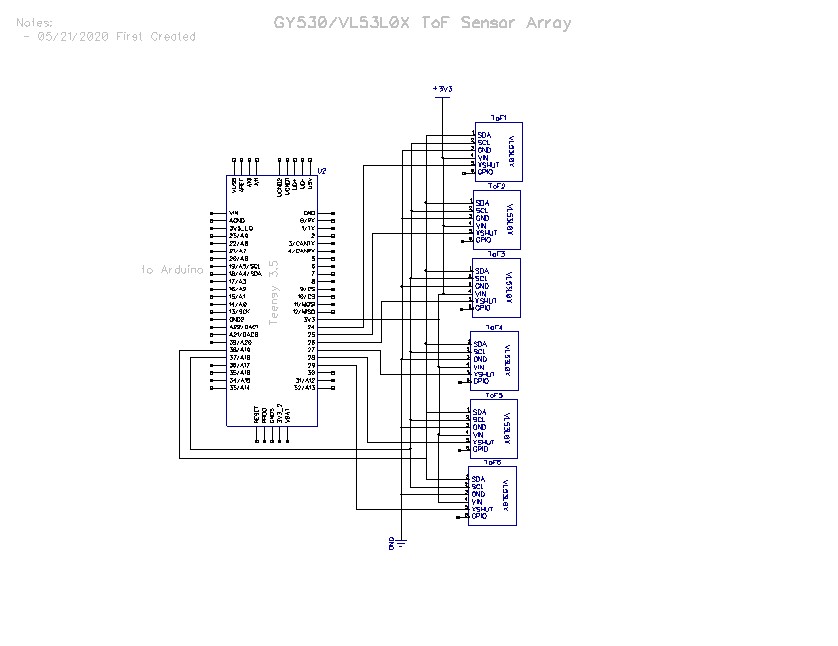
The Teensy would manage startup I2C address assignments for each of the six VL53L0X sensor modules via a secondary I2C bus, and would communicate distance and steering values to the Arduino Mega 2560 main controller via the system I2C bus.
22 May 2020 Update:
After some fumbling around and some quality time with the great folks on the Teensy forum, I managed to get a 3-sensor array working on a Teensy 3.5’s Wire1 I2C bus (SCL1/SDA1), using the Adafruit VL53L0X library. The code as it stands capitalizes on the little-known fact that when a Teensy 3.x is the compile target, there are three more ‘TwoWire’ objects availble – Wire1, Wire2, and Wire3. So, I was able to use the following code to instantiate and configure three VL53L0X objects:
January 18 2022 Note:
The ‘magic’ that creates the ‘Wire1’, ‘Wire2’, and ‘Wire3’ objects occurs in WireKinetis.h/cpp in the Arduino\hardware\teensy\avr\libraries\Wire folder.
1 2 3 4 5 6 7 8 9 10 11 12 13 14 15 16 17 18 19 20 21 22 23 24 25 26 27 28 29 30 31 32 33 34 35 36 37 38 39 40 41 42 43 44 45 46 47 48 49 50 51 52 53 54 55 56 57 58 59 60 61 62 63 64 65 66 67 68 69 70 71 72 73 74 75 76 77 78 79 80 81 82 83 84 85 86 87 88 89 90 91 92 93 94 95 96 97 98 99 100 101 102 103 104 105 106 107 108 109 110 111 112 113 114 115 116 117 118 119 120 121 122 123 124 125 126 127 128 129 130 131 132 |
/* Name: Triple_VL53L0X_Demo.ino Created: 5/19/2020 9:56:56 PM Author: FRANKNEWXPS15\Frank */ /* This code copied from the following post on the Adafruit forum: https://forums.adafruit.com/viewtopic.php?f=19&t=164589&p=808693&hilit=vl53l0x#p808693 And adapted to use it on the Wire1 I2C bus on a Teensy 3.5 */ #include <Wire.h> #include "Adafruit_VL53L0X.h" Adafruit_VL53L0X lidar_RF = Adafruit_VL53L0X(); //Right-front LIDAR (angled 30 deg forward) Adafruit_VL53L0X lidar_RC = Adafruit_VL53L0X(); //Center LIDAR Adafruit_VL53L0X lidar_RR = Adafruit_VL53L0X(); //Right-rear LIDAR (angled 30 deg rearward) //XSHUT required for I2C address init const int RF_XSHUT_PIN = 23; const int RC_XSHUT_PIN = 22; const int RR_XSHUT_PIN = 21; const int MAX_LIDAR_RANGE_MM = 1000; //make it obvious when nearest object is out of range uint16_t RF_Dist_mm; uint16_t RC_Dist_mm; uint16_t RR_Dist_mm; void setup() { Serial.begin(115200); //Teensy ignores rate parameter pinMode(RF_XSHUT_PIN, OUTPUT); pinMode(RC_XSHUT_PIN, OUTPUT); pinMode(RR_XSHUT_PIN, OUTPUT); // wait until serial port opens for native USB devices while (!Serial) { delay(1); } Serial.println("Teensy Adafruit Triple VL53L0X test"); //initialize 3 LIDAR sensors // 1. Reset all sensors by setting all of their XSHUT pins low for delay(10), then set // all XSHUT high to bring out of reset digitalWrite(RF_XSHUT_PIN, LOW); delay(10); digitalWrite(RC_XSHUT_PIN, LOW); delay(10); digitalWrite(RR_XSHUT_PIN, LOW); delay(10); digitalWrite(RF_XSHUT_PIN, HIGH); digitalWrite(RC_XSHUT_PIN, HIGH); digitalWrite(RR_XSHUT_PIN, HIGH); // 2. Keep sensor #1 awake by keeping XSHUT pin high, and put all other sensors into // shutdown by pulling XSHUT pins low digitalWrite(RC_XSHUT_PIN, LOW); digitalWrite(RR_XSHUT_PIN, LOW); // 4. Initialize sensor #1 with lox.begin(new_i2c_address) Pick any number but 0x29 and it // must be under 0x7F. Going with 0x30 to 0x3F is probably OK. if (!lidar_RF.begin(VL53L0X_I2C_ADDR+1, false, &Wire1)) { Serial.println(F("Failed to boot lidar_RF")); while (1); } // 5. Keep sensor #1 awake, and now bring sensor #2 out of reset by setting its XSHUT pin high. // 6. Initialize sensor #2 with lox.begin(new_i2c_address) Pick any number but 0x29 and whatever // you set the first sensor to digitalWrite(RC_XSHUT_PIN, HIGH); if (!lidar_RC.begin(VL53L0X_I2C_ADDR + 2, false, &Wire1)) { Serial.println(F("Failed to boot lidar_RC")); while (1); } // 7. Repeat for each sensor, turning each one on, setting a unique address. digitalWrite(RR_XSHUT_PIN, HIGH); if (!lidar_RR.begin(VL53L0X_I2C_ADDR + 3, false, &Wire1)) { Serial.println(F("Failed to boot lidar_RR")); while (1); } Serial.println(F("Init complete\n\nVL53L0X API Simple Ranging example\n\n")); Serial.printf("Time\tFront\tCenter\tRear\n"); } void loop() { VL53L0X_RangingMeasurementData_t measure; lidar_RF.rangingTest(&measure, false); // pass in 'true' to get debug data printout! if (measure.RangeStatus != 4) // phase failures have incorrect data { RF_Dist_mm = measure.RangeMilliMeter; if (RF_Dist_mm > MAX_LIDAR_RANGE_MM) RF_Dist_mm = MAX_LIDAR_RANGE_MM; } else RF_Dist_mm = 0; //delay(100); lidar_RC.rangingTest(&measure, false); // pass in 'true' to get debug data printout! if (measure.RangeStatus != 4) // phase failures have incorrect data { RC_Dist_mm = measure.RangeMilliMeter; if (RC_Dist_mm > MAX_LIDAR_RANGE_MM) RC_Dist_mm = MAX_LIDAR_RANGE_MM; } else RC_Dist_mm = 0; //delay(100); lidar_RR.rangingTest(&measure, false); // pass in 'true' to get debug data printout! if (measure.RangeStatus != 4) // phase failures have incorrect data { RR_Dist_mm = measure.RangeMilliMeter; if (RR_Dist_mm > MAX_LIDAR_RANGE_MM) RR_Dist_mm = MAX_LIDAR_RANGE_MM; } else RR_Dist_mm = 0; Serial.printf("%lu\t%d\t%d\t%d\n", millis(), RF_Dist_mm, RC_Dist_mm, RR_Dist_mm); delay(100); } |
Here’s some sample output:
1 2 3 4 5 6 7 8 9 10 11 12 13 14 15 16 17 18 19 20 |
Opening port Port open Teensy Adafruit Triple VL53L0X test Init complete VL53L0X API Simple Ranging example Time Front Center Rear 29366 446 566 133 29584 453 126 123 29802 449 83 111 30020 442 59 91 30237 435 60 85 30455 431 58 85 30673 427 53 86 30890 416 56 85 31108 413 57 83 31325 406 56 83 31543 400 54 84 31761 388 54 82 31978 366 51 84 32196 367 50 81 |
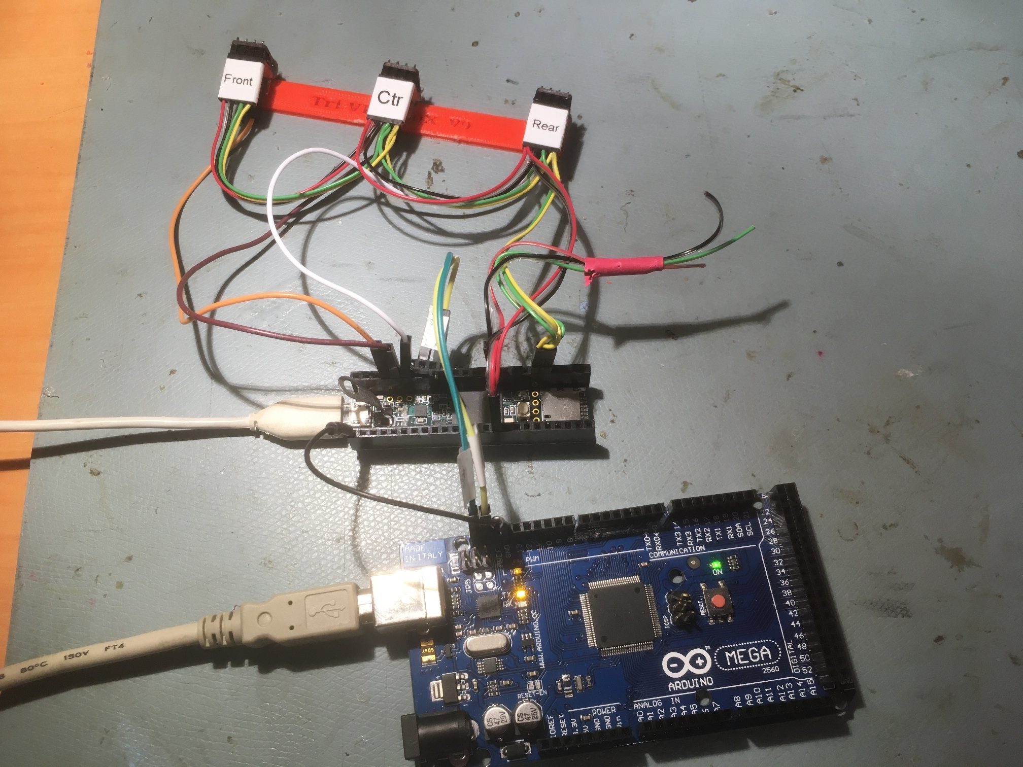
And the physical setup:
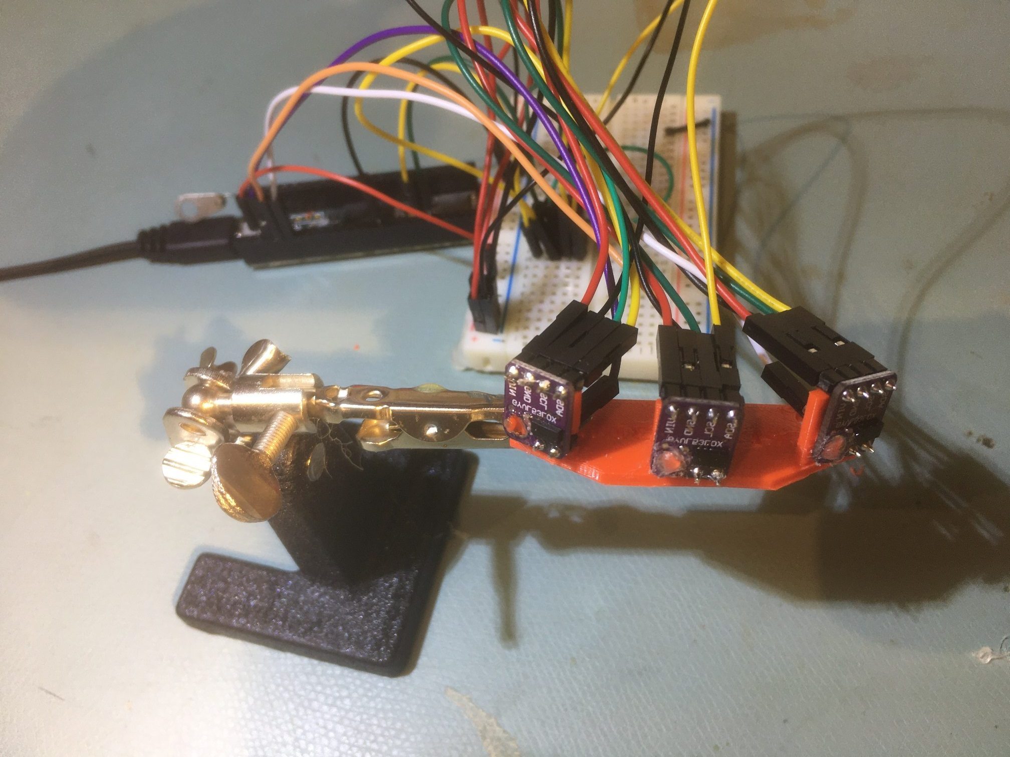
Triple VL53L0X LIDAR array. The two outside sensors are angled at 30 degrees. Teensy 3.5 in background
The next big questions are whether or not this 3-sensor array can be used to determine when Wall_E2 is oriented parallel to the nearest wall, and whether or not the steering value proposed in my previous post, namely
where the ‘l’, ‘r’ and ‘c’ subscripts denote the left/forward, right/rearward, and center sensor measured distances respectively.
23 May Update:
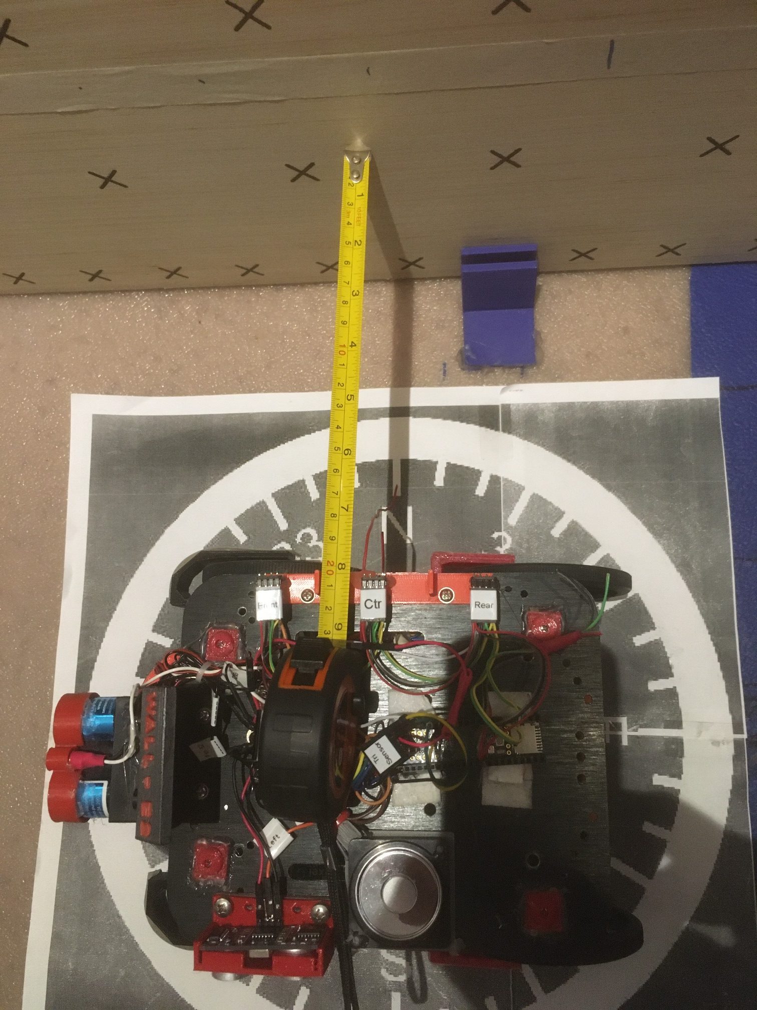
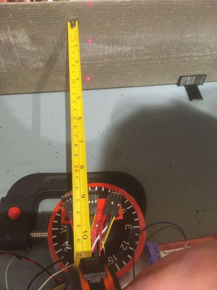
I’ve been improving my understanding of my triple-VL53L0X setup, and I think I’m to the point where I can try out the steering idea. Here’s the experimental setup:
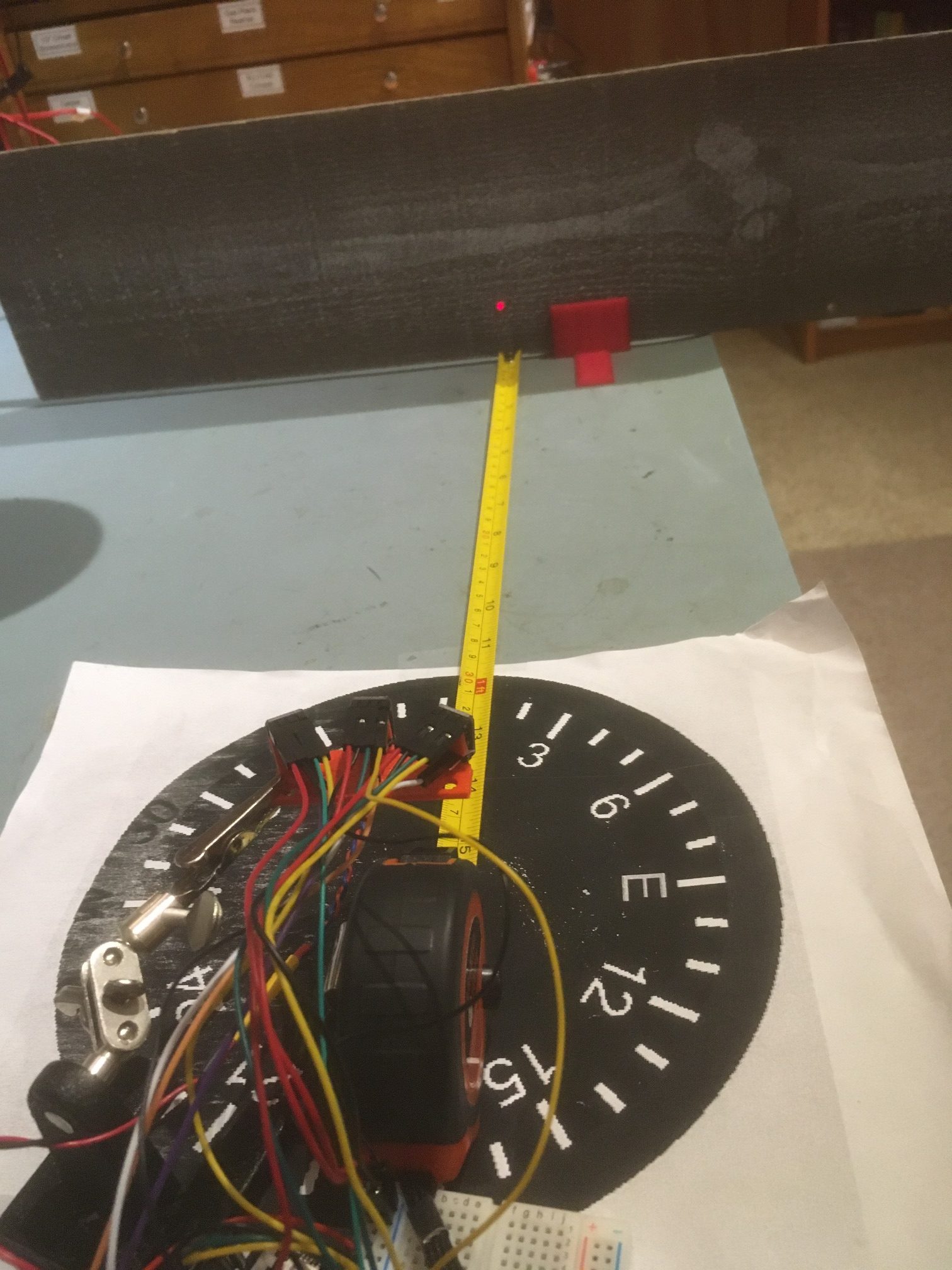
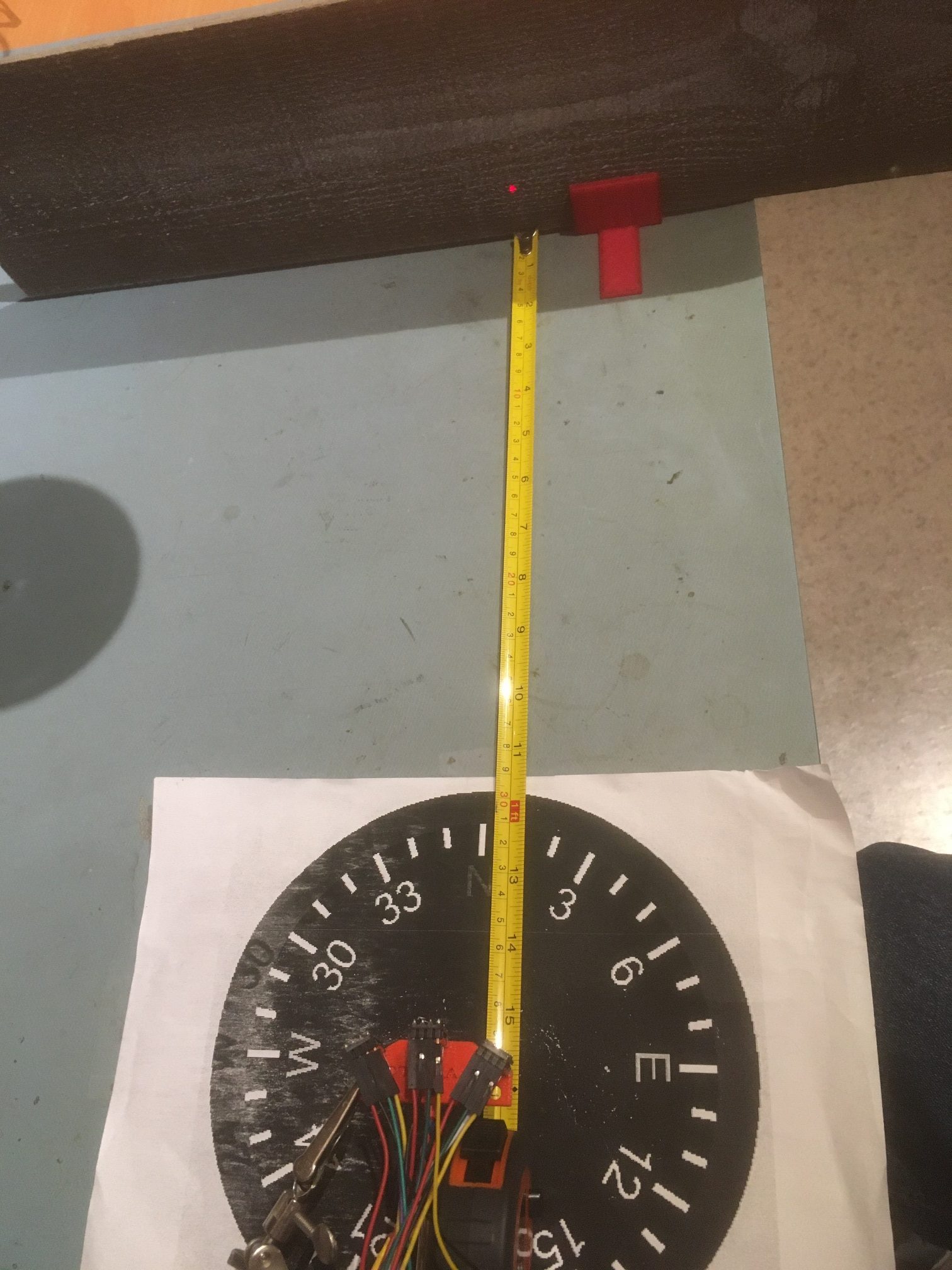
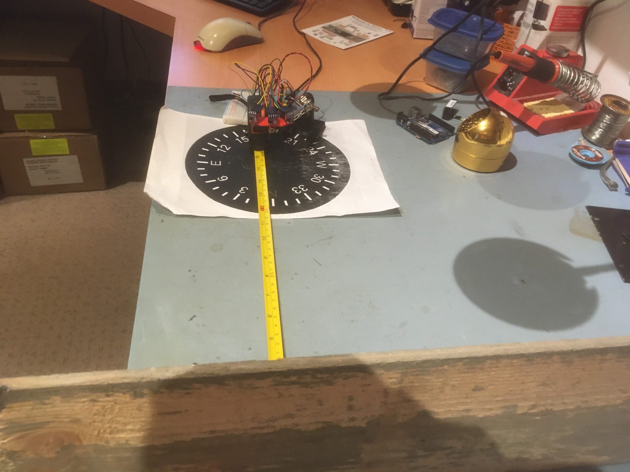
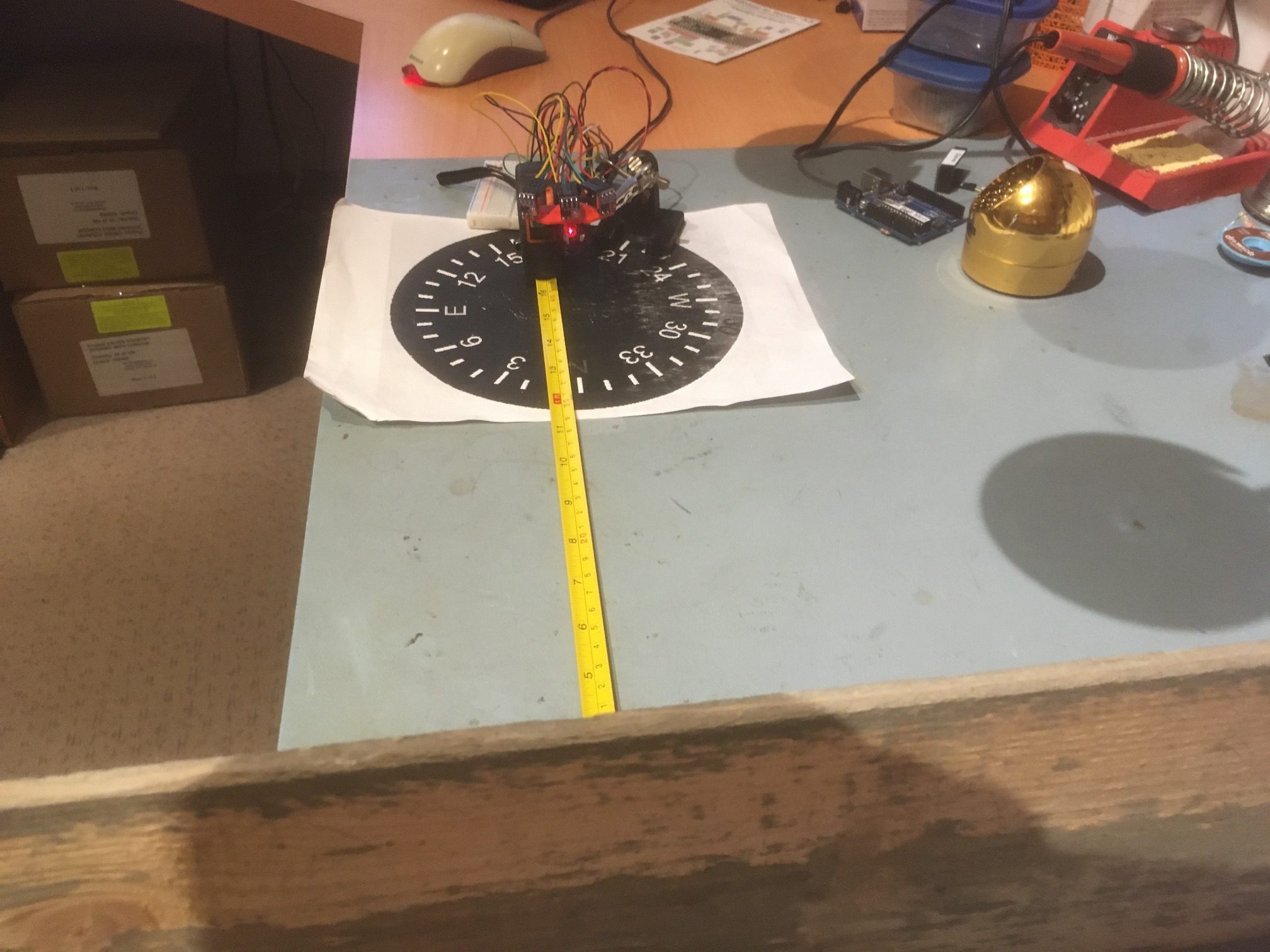
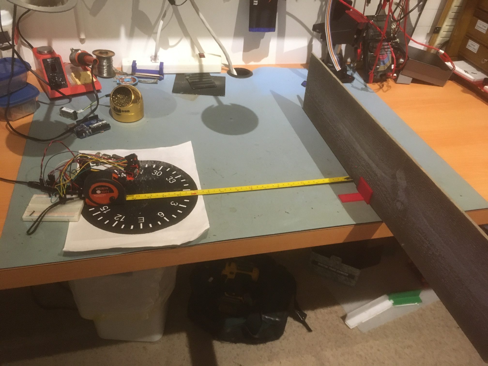
I have a wood barrier set up with a 40 cm offset from the center of the compass rose. Before getting started, I checked each sensor’s measured distance from the barrier by manually placing each sensor at the center of the compass rose, aligned as closely as possible with the perpendicular to the barrier. When I did this, the measured offsets were within a few mm of the actual distance as measured by the tape measure.
The plan is to rotate the sensor bracket from -30 degrees to +30 degrees relative to the normal perpendicular orientation, while recording the left, center, and right measured distances. Then I should be able to determine if the steering idea is going to work. In this experiment, I manually rotated the array from 0 (i.e. the center sensor aligned with the perpendicular to the barrier) to -30 degrees, and then in 10 degree steps from -30 to 30 degrees. The rotation was paused for a few seconds at each orientation. As shown in the plot below, the Steering Value looks very symmetric, and surprisingly linear – yay!
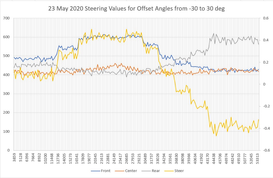
Steering values resulting from manualy rotating the triple VL53L0X array from -30 to 30 degrees
However, the above experiment exposed a significant problem with my array design. The 30 degree angular offset between the center sensor and the outer two sensors is too large; when the center sensor is oriented 30 degrees off perpendicular, the line-of-sight distance from the ‘off’ sensor to the wall is very near the range limit for the sensors, with the 40 cm nominal offset chosen for the test. I could reduce the problem by reducing the initial offset, but in the intended application the initial offset might be more than 40 cm, not less.
So, back to TinkerCad for yet another bracket rev. Isn’t having a 3D printer (or two, in my case) WONDERFUL! The new version has a 20 deg relative angle rather than 30, so when the center sensor is at 30 degrees relative to the wall, the outside one will be at 50 deg. Hopefully this will still allow good steering while not going ‘off the wall’ literally.
Revised sensor carrier with 20-deg offsets vs 30-deg
04 June 2020 Update:
In order to make accurate measurements of the triple-VL53L0X array performance, I needed a way to accurately and consistently rotate the array with respect to a nearby wall, while recording the distance measurements from each array element. A few years ago I had created a rotary table program to run a stepper motor for this purpose, but I hadn’t documented it very well, so I had to take some time away from this project to rebuild the tool I needed. The result was a nice, well-documented (this time) rotary scan table controlled by a Teensy 3.2, and a companion measurement program. The rotary scan table program can be synchronized with the measurement program via control pins, and the current step # and relative pointing angle can be retrieved from the scan table via I2C.
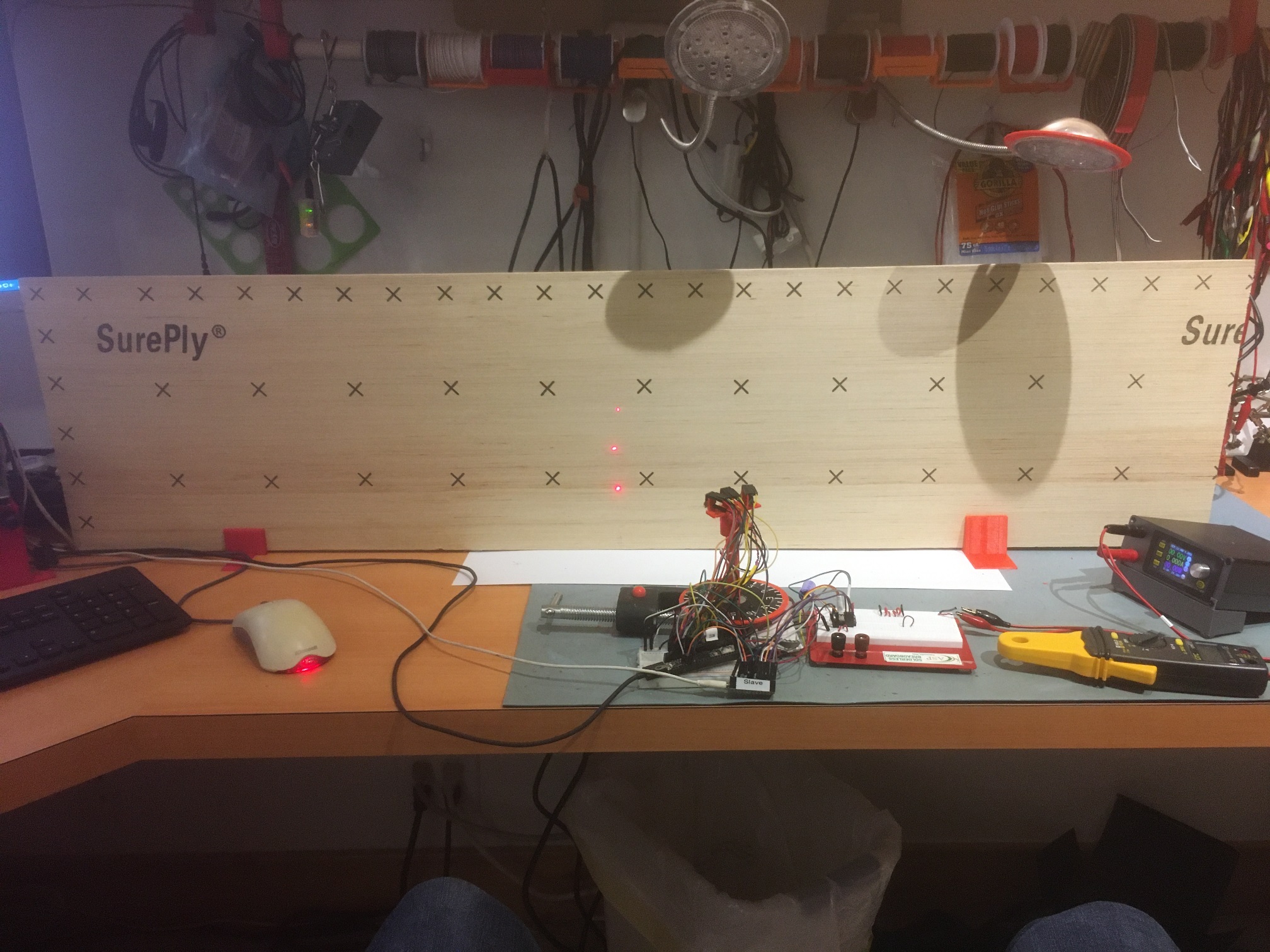
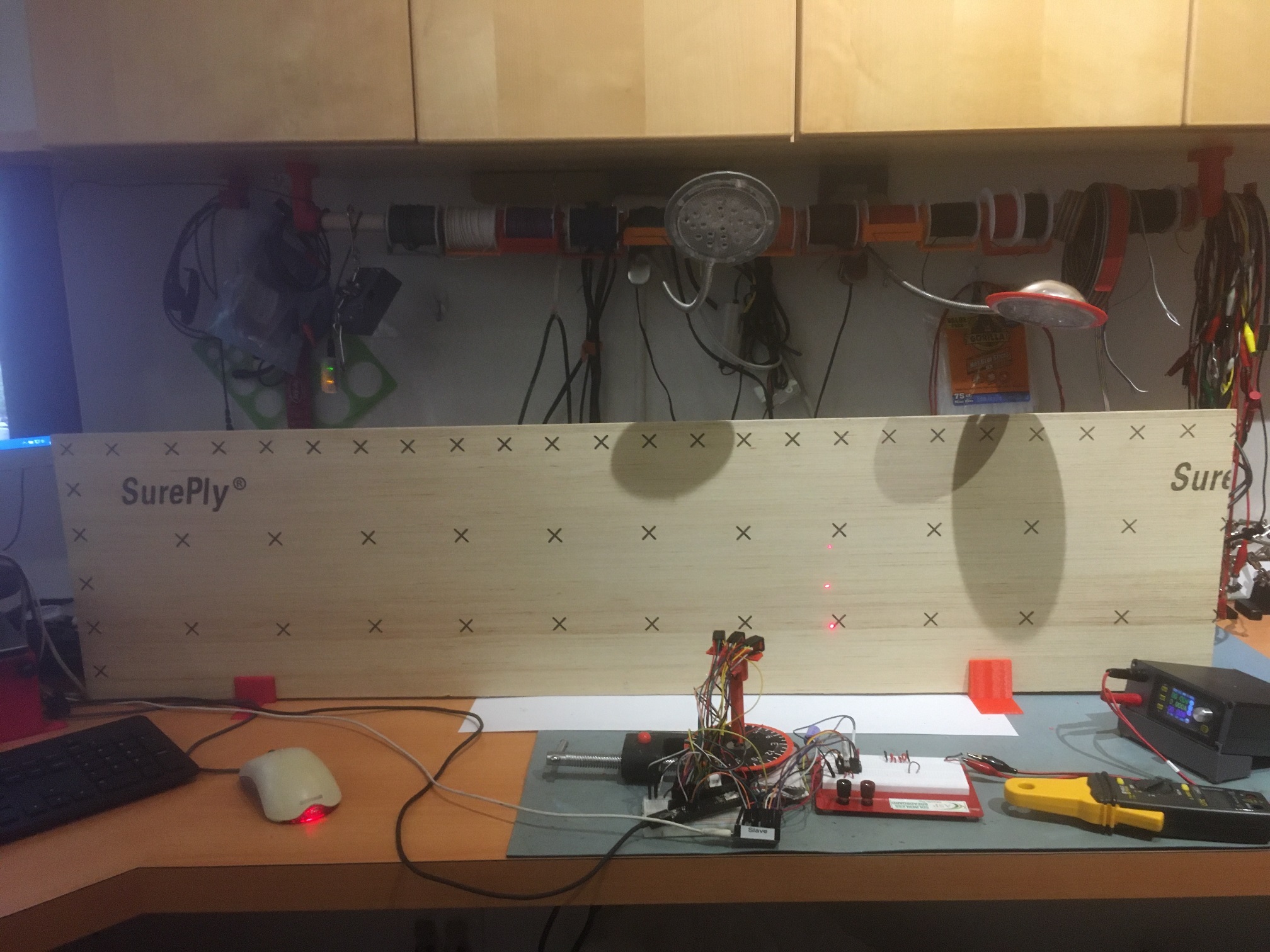
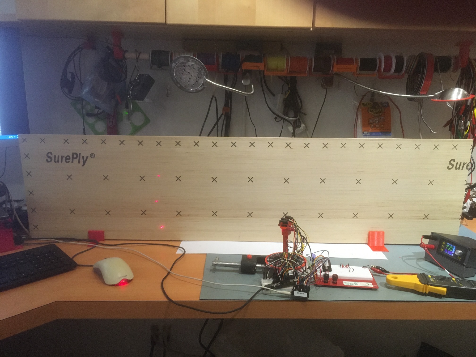
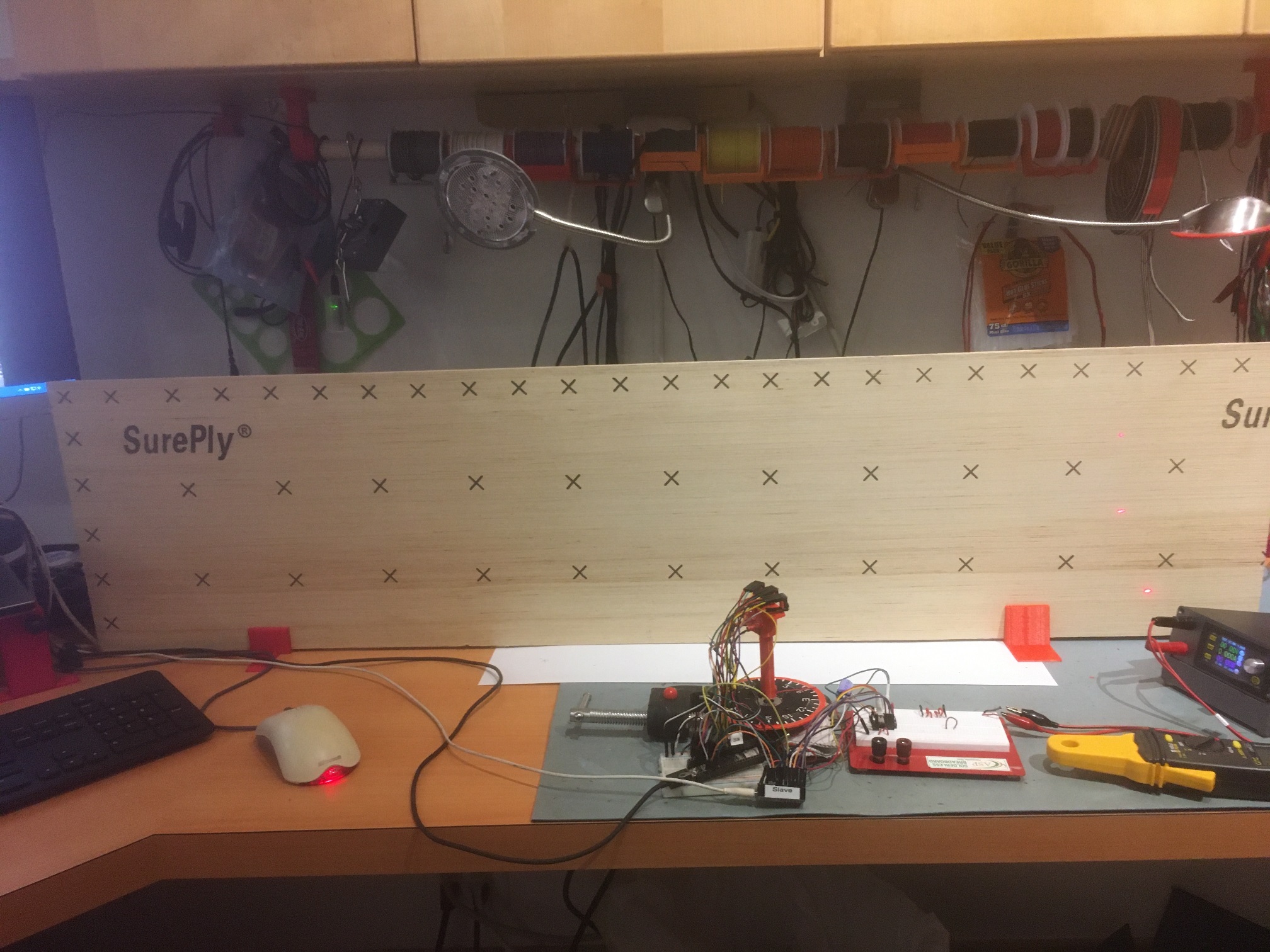
Here’s the test setup:
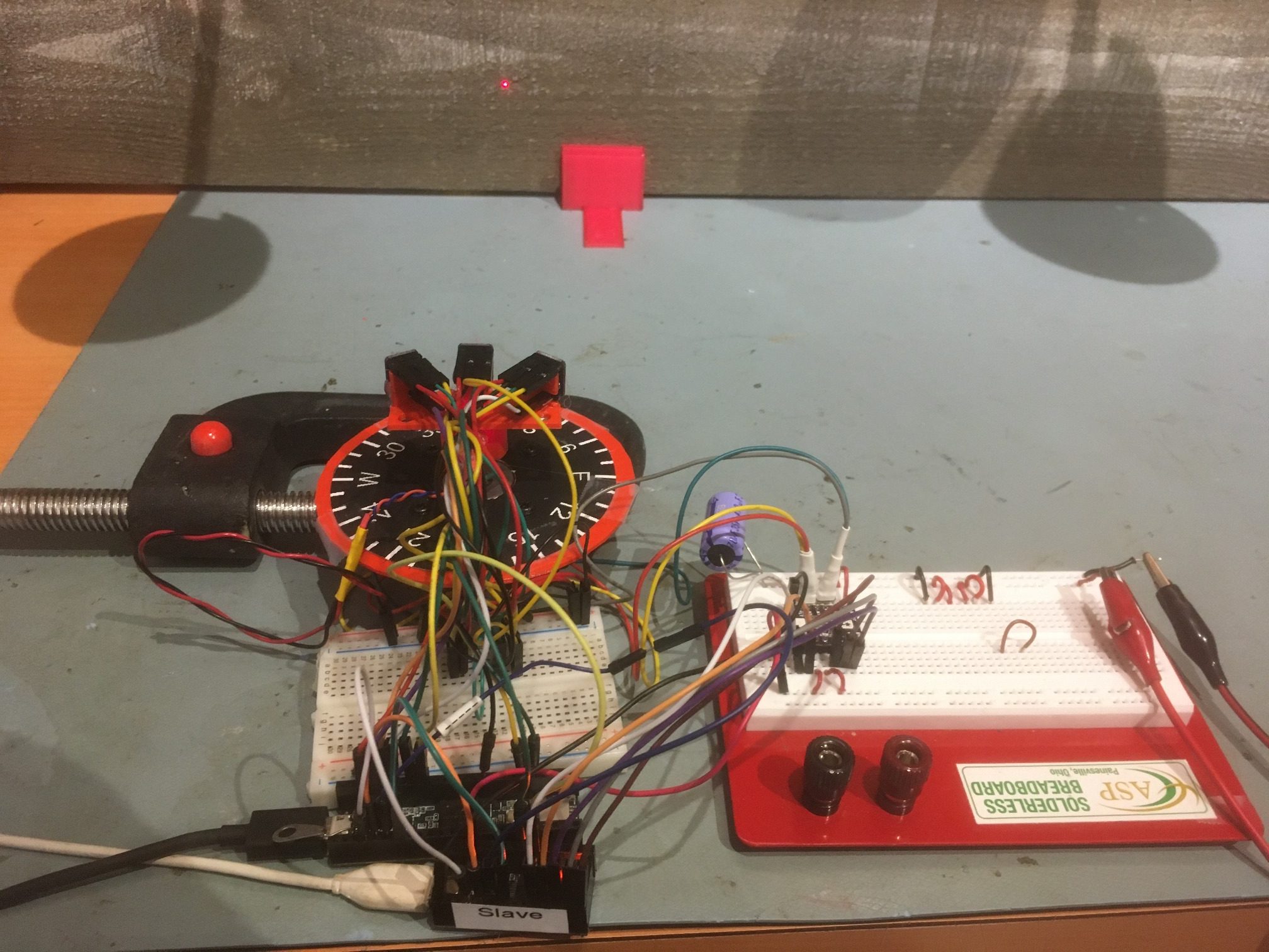
Test setup for triple VL53L0X angle sweeps. Board in background extends about .5m left and right of center.
And here’s a short video showing one scan (-20 to +20 deg)
I ran two scans – one from -30 to +30 deg, and another from -20 to +20 deg. Unfortunately, my test ‘wall’ isn’t quite long enough for the -30/+30 scan, and in addition the left-most sensor started picking up clutter from my PC in the -30 position. In any case, both scans showed a predictable ‘steering’ value transition from positive to negative at about +10 deg.
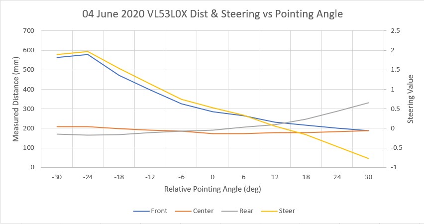
-30 to +30 deg scan. Note the steering value crosses zero at about +10 deg
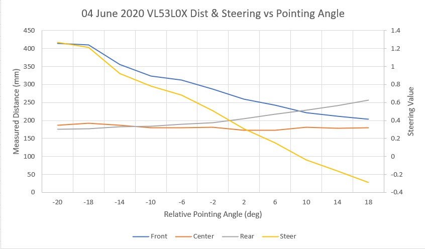
-20 to +20 deg scan. Note the steering value crosses zero at about +10 deg
09 June 2020 Update:
After this first series of scans, I discovered that my scan setup was not producing consistent results, and so all the data taken to this point was suspect. So, back to the drawing board.
Based on a comment on an earlier experiment made by john kvam of ST Microlectronics, regarding the 27 degree cone coverage of the photo beam from the LIDAR unit, I thought at least part of the problem was that the beam might be picking up the ‘floor’ (actually my desk surface in these first experiments). As a way of illuminating (literally) the issue, I created a new stepper motor mount assembly with holes for mounting three laser diodes – one straight ahead, one tilted down at 14 degrees, and one tilted up at 14 degrees. The combination of all three allows me to visualize the extents of the VL53L0X beam coverage on the target surface, as shown in the following photos.
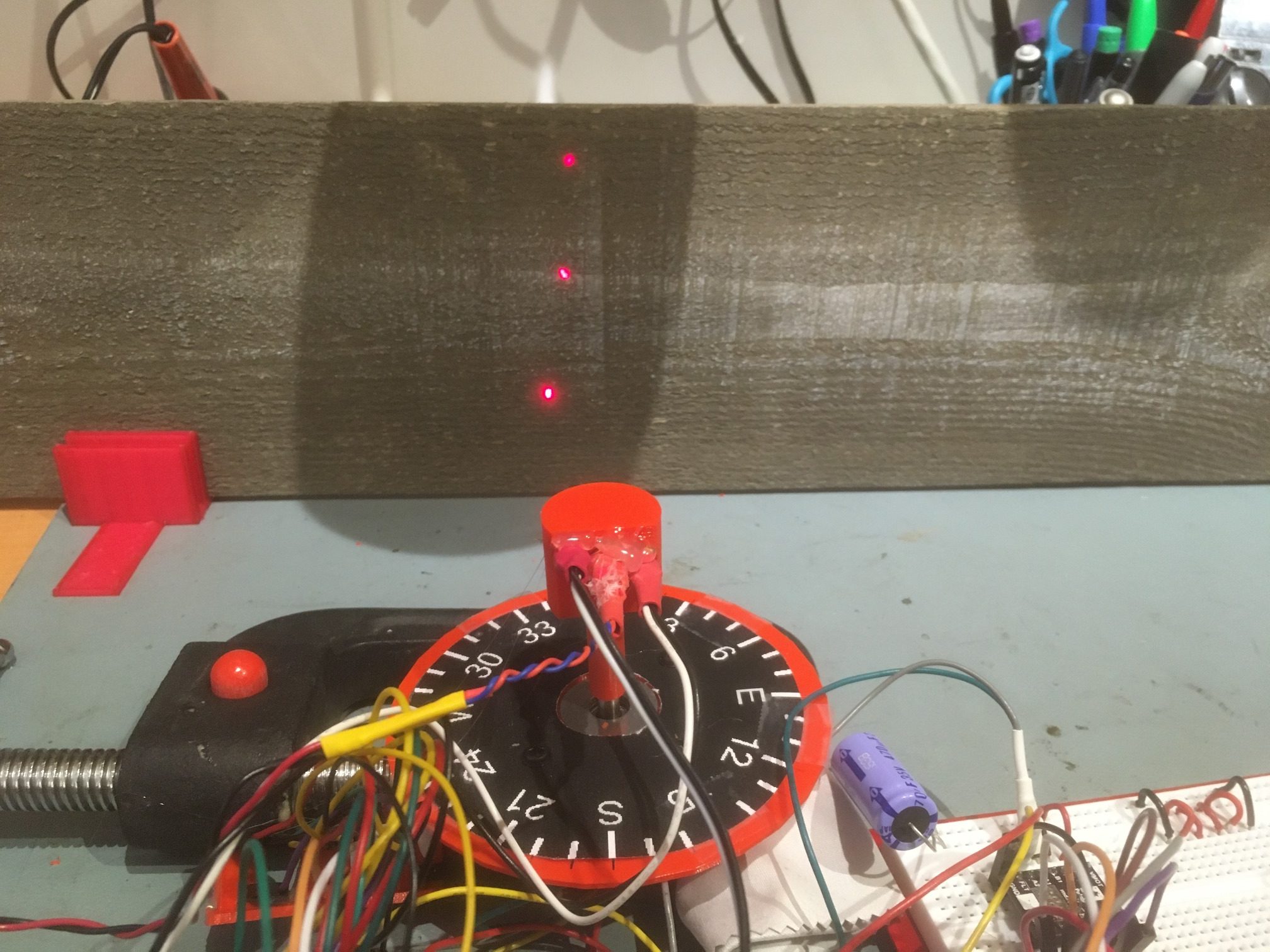
The second photo shows the situation with the ‘wall’ moved away until the beam extent indicator dots are just captured, with the distance measured to be about 220 mm. The following short video shows how the beam coverage changes as the relative angle between the center sensor and the wall changes.
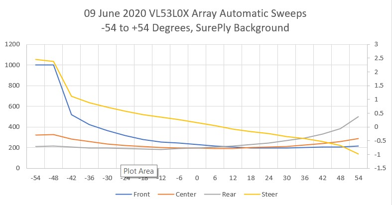
As shown in the video, the beam extents are fully intercepted by the 6″ wall only during the center portion of the scan, so the off-axis results start to get a little suspect after about 50 degrees off bore-sight. However, for +/- 30 to 40 degrees, the beam extents are fully on the ‘wall’, so those measurements should be OK. However, the actual measurements have a couple of serious problems, as follows:
- As shown in the above Excel plots, the ‘steering’ value, calculated as (Front-Rear)/Center crosses the zero line well to the right of center, even though the sensors themselves are clearly symmetric with the ‘wall’ at 0 degrees
- The scans aren’t repeatable; when I placed a pencil mark on the ‘wall’ at the center laser dot, ran a scan, and then looked at the laser dot placement after the ‘return to start position’ movement, the laser dot was well to the left of the pencil mark. After each scan, the start position kept moving left, farther and farther from the original start position.
So, I started over with the rotary table program; After some more research on the DRV8825, I became convinced that some or all of the problem was due to micro-stepping errors – or more accurately, to the user (me) not correctly adjusting the DRV8825 current-limiting potentiometer for proper micro-stepping operation. According to Pololu’s description of DRV8825 operation, if the current limit isn’t set properly, then micro-stepping may not operate properly. To investigate this more thoroughly, I revised my rotary table program to use full steps rather than micro-steps by setting the microstepping parameter to ‘1’. Then I carefully set the scan parameters so the scan would traverse from -30 to +30 steps (not degrees). When I did this, the scan was completely repeatable, with the ‘return to starting position’ maneuver always returning to the same place, as shown in the following short video
The above experiment was conducted with the DRV8825 current limit set for about 1A (VREF = 0.5V). According to information obtained from a Pololu support post on a related subject, I came to believe this current limit should be much lower – around 240-250 mA for proper microstepping operation, so I re-adjusted the current limiting pot for VREF = 0.126V.
After making this adjustment, I redid the full-step experiment and confirmed that I hadn’t screwed anything up with the current limit change – Yay!
Then I changed the micro-stepping parameter to 2, for ‘half-step’ operation, and re-ran the above experiment with the same parameters. The ‘2’ setting for micro-stepping should enable micro-stepping operation. As shown in the following video, the scan performed flawlessly, covering the -54 to 54 degree span using 60 micro-steps per scan step instead of the 30 previously, and returning precisely to the starting position – double Yay!
Next I tried a microstepping value of 8, with the same (positive) results. Then I tried a stepping value of 32, the value I started with originally. This also worked fine.
So, at this point I’m convinced that microstepping is working fine, with the current limit set to about 240 mA as noted above. This seems to fully address the second bullet above, but as shown in the plot below taken with microstepping = 32 and with data shown from -30 to +54 degrees), I still have a problem with the ‘steering’ value not being synchronized with the actual pointing angle of the array sensor.
Next I manually acquired sensor data from -30 to +30 degrees by rotating the de-energized stepper motor shaft by hand and recording the data from all three sensors. After recording them in Excel and plotting the result, I got the following chart.
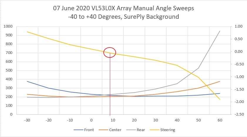
This looks pretty good, except for two potentially serious problems:
- The ‘steering’ value, defined as (Front Distance – Rear Distance)/Center Distance, is again skewed to the right of center, this time about 8 degrees. Not a killer, but definitely unwanted.
- Rotation beyond 30 degrees left of center is not possible without getting nonsense data from the Front (left-hand) sensor, but I can rotate 60 degrees to the right while still getting good data, and this is with much more ‘wall’ available to the left than to the right, as shown in the following photo
-30 deg relative to center
+30 deg relative to center
-60 deg relative to center
+60 deg relative to center
After finishing this, I received a reply to a question I had asked on the Pololu support forum about micro-stepping and current limiting with the Pololu DRV8825. The Pololu guy recommended that the current limit be set to the coil current rating (350 mA for the Adafruit NEMA 17 stepper motor I’m using), or 0.175V on VREF. So, I changed VREF from 0.122V to 0.175V and re-verified proper micro-stepping performance. Here’s a plot using the new setup, micro-stepping set to 32, -54 to +54 deg sweep, 18 steps of 6 deg each.
and a short video showing the sweep action.
In the video, note that at the end, the red wire compass heading pointer and the laser dots return precisely to their starting points – yay!
So, at this point everything is working nicely, except I still can’t figure out why the steering value zero doesn’t occur when the sensor array is oriented parallel to the ‘wall’. I’m hoping John, the ST Micro guy, can shed some light (pun intended) on this 😉
11 June 2020 Update.
I think I figured out why the steering value zero didn’t occur when the sensor array was oriented parallel to the wall, and it was, as is usually the case, a failure of the gray matter between my ears ;-).
The problem was the way I was collecting the data with the scanner program that runs the rotary table program. The scanner program wasn’t properly synchronizing the sensor measurements with the rotary table pointing angle. Once I corrected this software error, I got the following plot (the test setup for this plot still has the left & right sensors physically reversed).
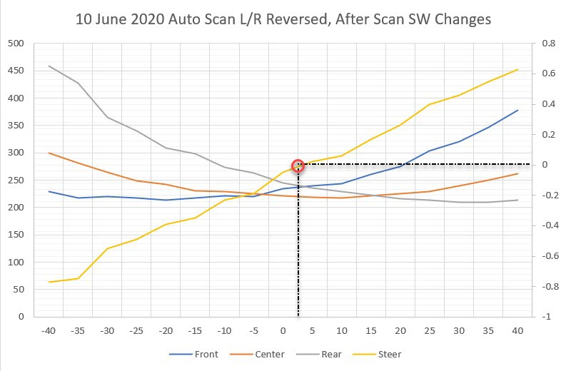
As can be seen in the above plot, the steering value y-axis crossover now occurs very close to zero degrees, where the sensor array is oriented parallel to the wall.
12 June 2020 Update
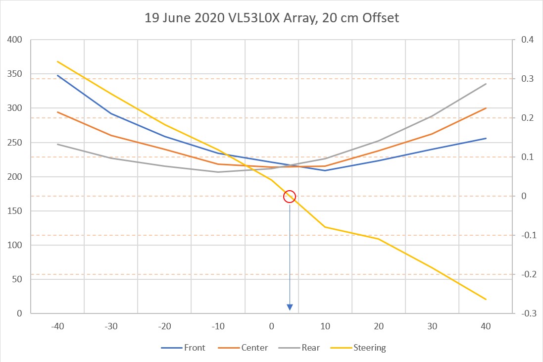
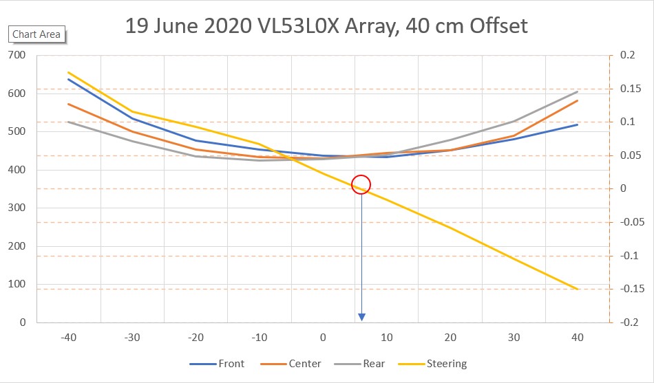
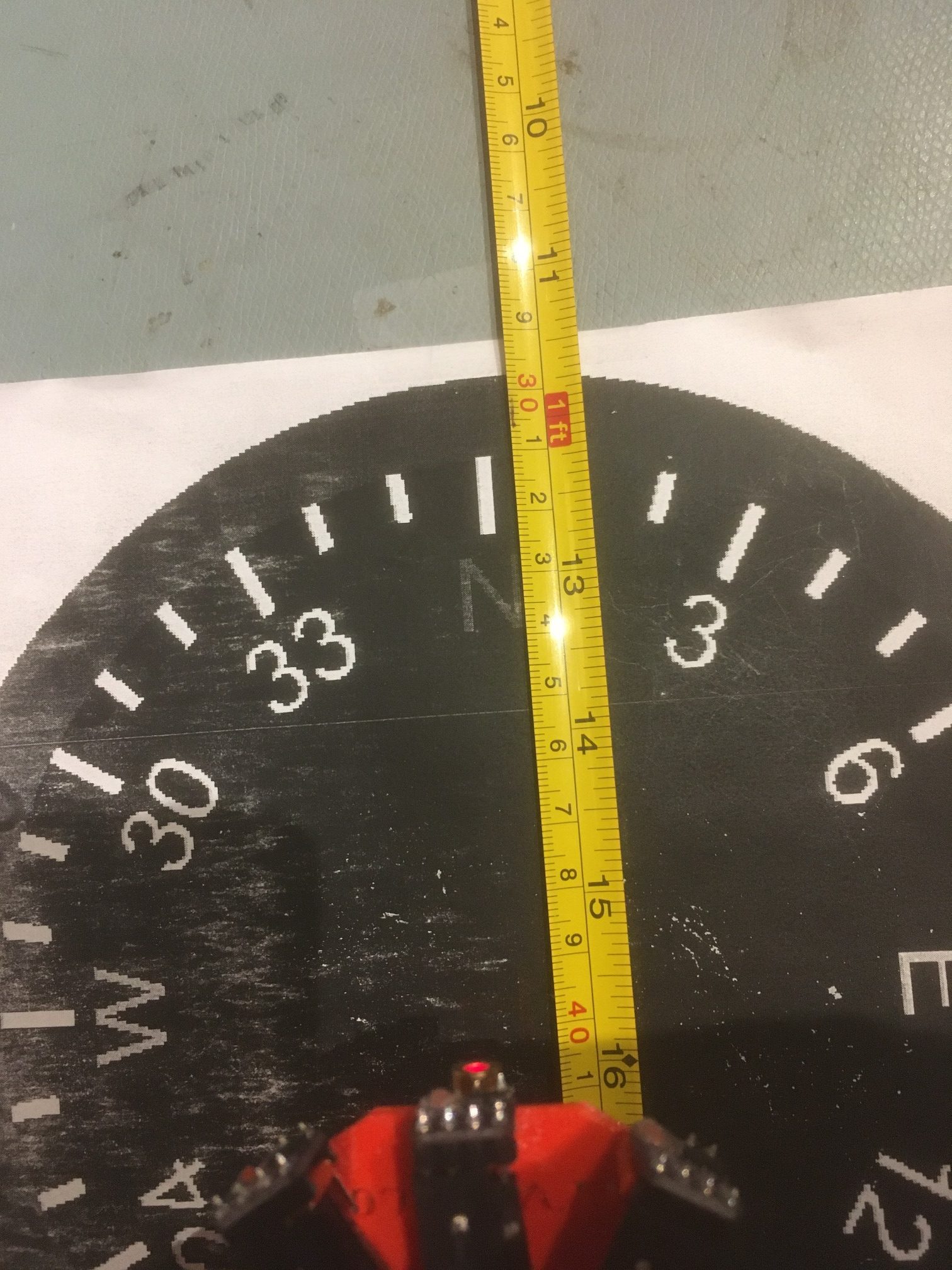
After numerous additional steering value vs angle scans, I’m reaching the conclusion that the VL53L0X sensors have the same sort of weakness as the ‘ping’ sensors – they aren’t particularly accurate off-perpendicular. To verify this, I removed the sensors from my 3-sensor array bracket and very carefully measured the distance from each sensor position to the target ‘wall’ using a tape measure and a right-angle draftsman’s triangle, with the results shown in the following Excel plot. Measuring the off-perpendicular distances turned out to be surprisingly difficult due to the very small baseline presented by the individual sensor mounting surfaces and the width of the tape measure tape. I sure wish I had a better way to make these measurements – oh, wait – that’s what I was trying to do with the VL53L0X sensors! ;-).
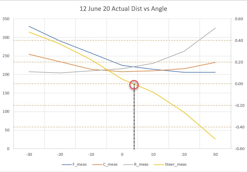
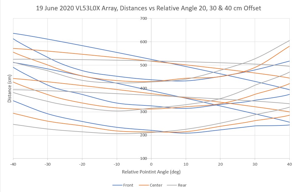
With just the physical measurements, the steering value crosses the y-axis very close to zero degrees relative to parallel, plus/minus measurement error as expected. One would expect even better accuracy when using a sensor that can measure distances with milometer accuracy, but that doesn’t seem to be the case. In the following Excel plot, the above tape measure values are compared to an automatic scan using the VL53L0X sensors. As can be seen, there are significant differences between what the sensors report and the actual distance, and these errors aren’t constant with angular orientation (otherwise they could be compensated out).
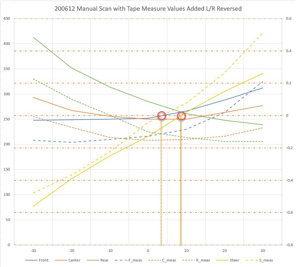
For example, in the above plot the difference between the solid green (rear sensor distance) and dashed green (rear sensor mounting surface tape measure distance) is about 80 mm at -30 degrees, but only about 30 mm at +30 degrees. The difference between the measurements for the blue (front) sensor and the tape measure numbers is even more dramatic.
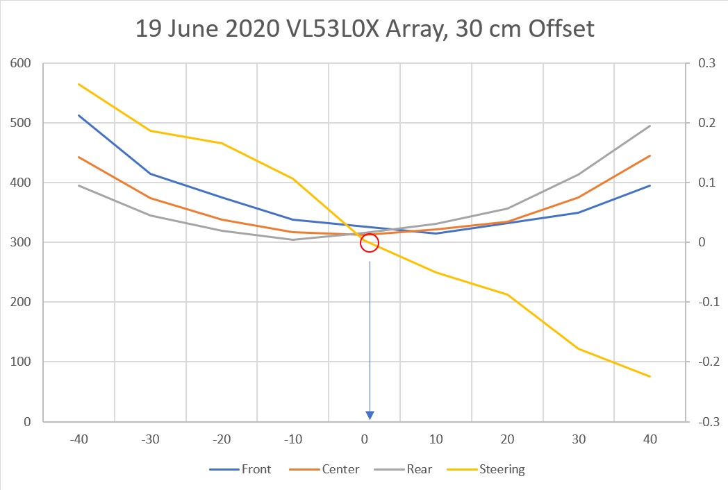
So it is clear that my idea of orienting the sensors at angles to each other is fundamentally flawed, as this arrangement exacerbates the relative angle between the ‘outside’ sensor orientations and the target wall when the robot isn’t oriented parallel to the wall. For instance, with the robot oriented at 30 degrees to the wall, one of the sensors will have an orientation of at least 50 degrees relative to the wall.
So my next idea is to try a three sensor array again, but this time they will all be oriented at the same angle, as shown below:
The idea here is that this will reduce the maximum relative angle between any sensor and the target wall to just the robot’s orientation.
3-sensor linear array
I attached the three VL53L0X sensors to the linear array mount and ran an automatic scan from -30 to +30 degrees, with much better results than with the angled-off array, as shown in the Excel plot below:
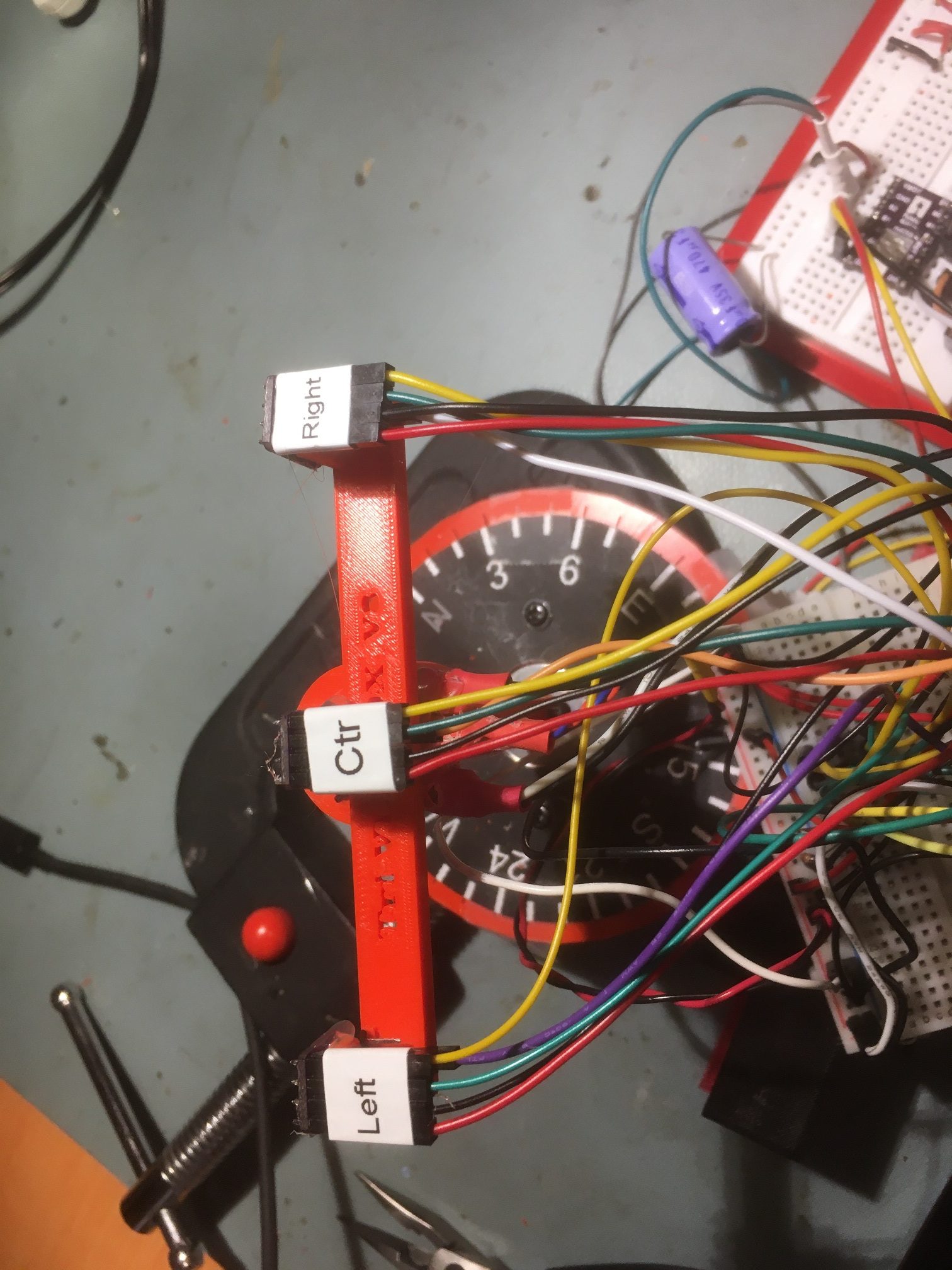
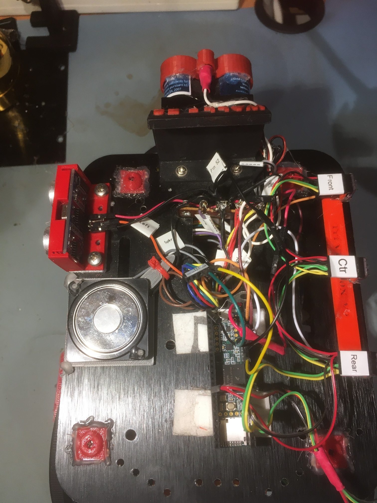
VL53L0X sensors attached to the linear array mount. Note the nomeclature change
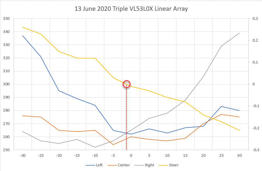
Triple sensor linear array automatic scan. Left/Right curve are very symmetric
So, the linear array performance is much better than the previous ‘angled-off’ arrangement, probably because the off-perpendicular ‘look’ angle of the outside sensors is now never more than the scan angle; at -30 and +30 degrees, the look angle is still only -30 and +30 degrees. Its clear that keeping the off-perpendicular angle as low as possible provides significantly greater accuracy. As an aside, the measured perpendicular distance from the sensor surface to the target ‘wall’ was almost exactly 250 mm, and the scan values at 0 degrees were 275, 238, and 266 mm for the left, center, and right sensors respectively. so the absolute accuracy isn’t great, but I suspect most of that error can be calibrated out.
13 June 2020 Update:
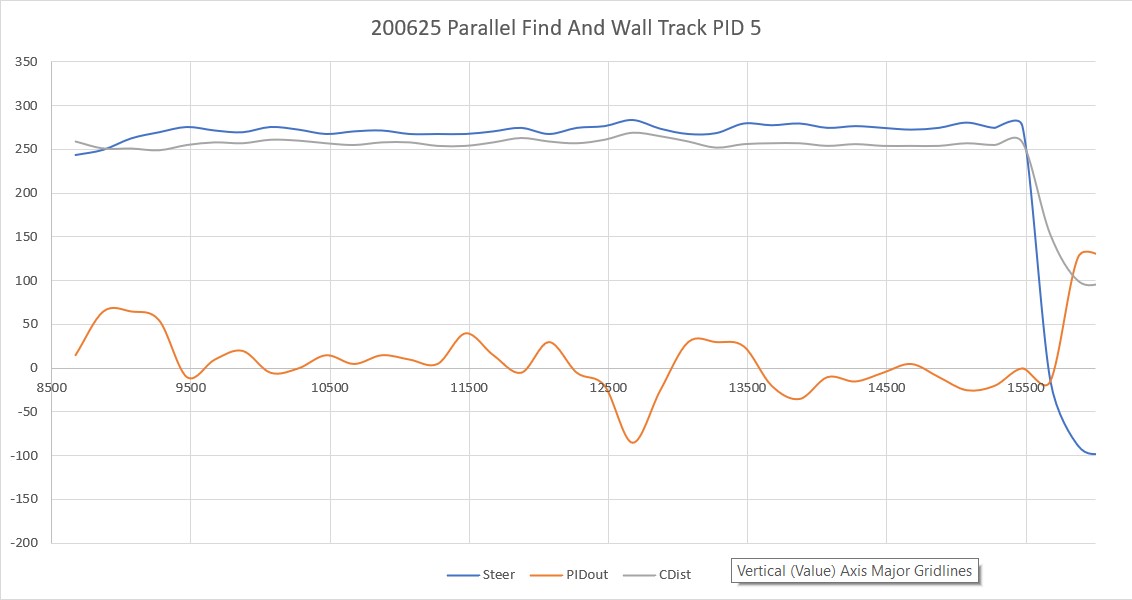
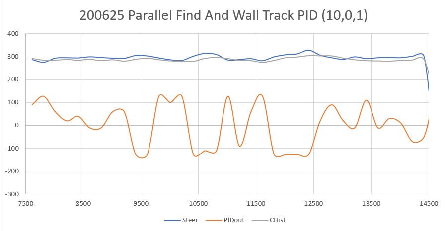
So, now that I have a decently-performing VL53L0X sensor array, the next step is to verify that I can actually use it to orient the robot parallel to the nearest wall, and to track the wall at a specified offset using a PID engine.
My plan is to create a short Arduino/Teensy program that will combine the automated scan program and the motor driver program to drive the stepper motor to maintain the steering value at zero, using a PID engine. On the actual robot, this algorithm will be used to track the wall at a desired offset. For my test program, I plan to skew the ‘wall’ with respect to the stepper motor and verify that the array orientation changes to maintain a wall-parallel orientation.
14 June 2020 Update:
I got the tracking program running last night, and was able to demonstrate effective ‘parallel tracking’ with my new triple VL53L0X linear sensor array, as shown in the following video
If anyone is interested in the tracking code, here it is: It’s pretty rough and has lots of bugs, but it shows the method.
1 2 3 4 5 6 7 8 9 10 11 12 13 14 15 16 17 18 19 20 21 22 23 24 25 26 27 28 29 30 31 32 33 34 35 36 37 38 39 40 41 42 43 44 45 46 47 48 49 50 51 52 53 54 55 56 57 58 59 60 61 62 63 64 65 66 67 68 69 70 71 72 73 74 75 76 77 78 79 80 81 82 83 84 85 86 87 88 89 90 91 92 93 94 95 96 97 98 99 100 101 102 103 104 105 106 107 108 109 110 111 112 113 114 115 116 117 118 119 120 121 122 123 124 125 126 127 128 129 130 131 132 133 134 135 136 137 138 139 140 141 142 143 144 145 146 147 148 149 150 151 152 153 154 155 156 157 158 159 160 161 162 163 164 165 166 167 168 169 170 171 172 173 174 175 176 177 178 179 180 181 182 183 184 185 186 187 188 189 190 191 192 193 194 195 196 197 198 199 200 201 202 203 204 205 206 207 208 209 210 211 212 213 214 215 216 217 218 219 220 221 222 223 224 225 226 227 228 229 230 231 232 233 234 235 236 237 238 239 240 241 242 243 244 245 246 247 248 249 250 251 252 253 254 255 256 257 258 259 260 261 262 263 264 265 266 267 268 269 270 271 272 273 274 275 276 277 278 279 280 281 282 283 284 285 286 287 288 289 290 291 292 293 294 295 296 297 298 299 300 301 302 303 304 305 306 307 308 309 310 311 312 313 |
/* Name: TriVL53L0XAutoOrient.ino Created: 6/13/2020 5:40:27 PM Author: FRANKNEWXPS15\Frank This program is intended to verify that I can use my new triple VL53L0X linear array to track angular orientation changes in a nearby wall. The idea is to calculate a steering value from the array values and use the value to drive a stepper motor to zero the steering value. The program uses the sensor measurment code from TeensyTripleVL53L0XAngleScanV1.ino and the stepper motor control code from Teensy_DRV8825_Rotary_Scan_Table.ino */ #include <Wire.h> #include "Adafruit_VL53L0X.h" #include "I2C_Anything.h" #include <PID.h> //moved here 02/09/19 #include "DRV8825.h"//From Teensy_DRV8825_Rotary_Scan_Table.ino Adafruit_VL53L0X lidar_RF = Adafruit_VL53L0X(); //Right-front LIDAR (angled 30 deg forward) Adafruit_VL53L0X lidar_RC = Adafruit_VL53L0X(); //Center LIDAR Adafruit_VL53L0X lidar_RR = Adafruit_VL53L0X(); //Right-rear LIDAR (angled 30 deg rearward) //XSHUT required for I2C address init const int RF_XSHUT_PIN = 23; const int RC_XSHUT_PIN = 22; const int RR_XSHUT_PIN = 21; const int RED_LASER_PIN = 0; const int MAX_LIDAR_RANGE_MM = 1000; //make it obvious when nearest object is out of range uint16_t RF_Dist_mm; uint16_t RC_Dist_mm; uint16_t RR_Dist_mm; //experiment with PID control for wall tracking double Setpoint, SteeringVal, Output;//10/06/17 chg input variable name to something more descriptive PID myPID(&SteeringVal, &Output, &Setpoint, 200, 0.0, 0.0, REVERSE);//10/15/17 'final' setup const int STEP_MULT_FACTOR = 10; int motorStepsToMove = 0; //used to steer array for parallel orientation //const int PID_OUTPUT_LIMIT = 100; //06/13/20 just a guess for now //const int PID_OUTPUT_LIMIT = 500; //06/13/20 just a guess for now const int PID_OUTPUT_LIMIT = 1000; //06/13/20 just a guess for now //From Teensy_DRV8825_Rotary_Scan_Table.ino #pragma region MOTOR_CONSTANTS // Motor steps per revolution. Most steppers are 200 steps or 1.8 degrees/step //06/02/20 now using Pololu DRV8825 const int MOTOR_STEPS_PER_REV = 200; //const int MICROSTEPS_PER_STEP = 32; const int MICROSTEPS_PER_STEP = 8; //have to reduce microstepping to get max RPM up past 20 //const int MICROSTEPS_PER_STEP = 4; //have to reduce microstepping to get max RPM up past 20 const int MICROSTEPS_PER_REV = MICROSTEPS_PER_STEP * MOTOR_STEPS_PER_REV; const float DEG_PER_MICROSTEP = 360 / (float)MICROSTEPS_PER_REV; //const int DEFAULT_RPM = 6; //const int DEFAULT_RPM = 20; const int DEFAULT_RPM = 40; //const int DEFAULT_RPM = 60; const int POSITIONING_SPEED_RPM = 20; const int DEFAULT_MOTOR_STEPS_TO_MOVE = 10; #pragma endregion Motor Constants //const int SENSOR_MEASUREMENT_INTERVAL_MSEC = 100; //const int SENSOR_MEASUREMENT_INTERVAL_MSEC = 10; const int SENSOR_MEASUREMENT_INTERVAL_MSEC = 1; #pragma region PIN_ASSIGNMENTS const int DIR = 8; const int STEP = 9; const int SLEEP = 13; // optional (just delete SLEEP from everywhere if not used) const int MODE0 = 10; const int MODE1 = 11; const int MODE2 = 12; #pragma endregion Pin Assignments DRV8825 stepper(MOTOR_STEPS_PER_REV, DIR, STEP, SLEEP, MODE0, MODE1, MODE2); bool bGoingUp = true; int dirSign = 1; elapsedMillis mSecSinceLastMeasurement = 0; void setup() { //from scan program Wire.begin(); Wire.setClock(100000); Wire.setSCL(18); Wire.setSDA(19); Serial.begin(115200); //Teensy ignores rate parameter // wait until serial port opens for native USB devices while (!Serial) { delay(1); } delay(5000); //05/28/20 - this delay is necessary AFTER Serial instantiation! Serial.printf("Teensy Triple VL53L0X Angle Scan Program\n"); pinMode(RF_XSHUT_PIN, OUTPUT); pinMode(RC_XSHUT_PIN, OUTPUT); pinMode(RR_XSHUT_PIN, OUTPUT); pinMode(RED_LASER_PIN, OUTPUT); //initialize 3 LIDAR sensors // 1. Reset all sensors by setting all of their XSHUT pins low for delay(10), then set // all XSHUT high to bring out of reset digitalWrite(RF_XSHUT_PIN, LOW); delay(10); digitalWrite(RC_XSHUT_PIN, LOW); delay(10); digitalWrite(RR_XSHUT_PIN, LOW); delay(10); digitalWrite(RF_XSHUT_PIN, HIGH); digitalWrite(RC_XSHUT_PIN, HIGH); digitalWrite(RR_XSHUT_PIN, HIGH); // 2. Keep sensor #1 awake by keeping XSHUT pin high, and put all other sensors into // shutdown by pulling XSHUT pins low digitalWrite(RC_XSHUT_PIN, LOW); digitalWrite(RR_XSHUT_PIN, LOW); // 3. Initialize sensor #1 if (!lidar_RF.begin(VL53L0X_I2C_ADDR + 1, false, &Wire1)) { Serial.println(F("Failed to boot lidar_RF")); while (1); } // 4. Keep sensor #1 awake, and now bring sensor #2 out of reset by setting its XSHUT pin high. // 5. Initialize sensor #2 with lox.begin(new_i2c_address) Pick any number but 0x29 and whatever // you set the first sensor to digitalWrite(RC_XSHUT_PIN, HIGH); if (!lidar_RC.begin(VL53L0X_I2C_ADDR + 2, false, &Wire1)) { Serial.println(F("Failed to boot lidar_RC")); while (1); } // 6. Repeat for last sensor. digitalWrite(RR_XSHUT_PIN, HIGH); if (!lidar_RR.begin(VL53L0X_I2C_ADDR + 3, false, &Wire1)) { Serial.println(F("Failed to boot lidar_RR")); while (1); } //From Teensy_DRV8825_Rotary_Scan_Table.ino stepper.begin(DEFAULT_RPM); // if using enable/disable on ENABLE pin (active LOW) instead of SLEEP uncomment next line // stepper.setEnableActiveState(LOW); stepper.enable(); /* * Microstepping mode: 1, 2, 4, 8, 16 or 32 (where supported by driver) * Mode 1 is full speed. * Mode 32 is 32 microsteps per step. * The motor should rotate just as fast (at the set RPM), * but movement precision is increased, which may become visually apparent at lower RPMs. */ stepper.setMicrostep(MICROSTEPS_PER_STEP); // Set microstep mode //PID initialization //Step1: Initialize PID for homing //set the target value Setpoint = 0.05; //10/15/17 this seems to be the best value for now //turn the PID on myPID.SetMode(AUTOMATIC); //set the limits myPID.SetOutputLimits(-PID_OUTPUT_LIMIT, PID_OUTPUT_LIMIT); //myPID.SetSampleTime(50); //decrease sampling interval from default 100 mSec myPID.SetSampleTime(10); //decrease sampling interval from default 100 mSec //DEBUG!! //print out PID parameters Serial.printf("myPID Parameters (Kp,Ki,Kd,DIR) = (%2.2f,%2.2f,%2.2f,%d)\n", myPID.GetKp(), myPID.GetKi(), myPID.GetKd(), myPID.GetDirection()); //DEBUG!! //turn the laser OFF digitalWrite(RED_LASER_PIN, LOW); Serial.printf("\nInit complete\n \n"); Serial.printf("Left\tCenter\tRight\tSteer\n"); } void loop() { //experiment with using PID for auto-orientation //By default, computes new output approx 10 times/sec (use SetSampleTime() to change) //if (myPID.Compute())//if Compute returns TRUE, Output has new value //{ // motorStepsToMove = STEP_MULT_FACTOR * (int)Output; // stepper.move(motorStepsToMove); //} if (mSecSinceLastMeasurement >= SENSOR_MEASUREMENT_INTERVAL_MSEC) { mSecSinceLastMeasurement -= SENSOR_MEASUREMENT_INTERVAL_MSEC; TakeAndDisplayMeasurement(); if (myPID.Compute())//if Compute returns TRUE, Output has new value { //Serial.printf("SteeringVal = %2.3f, New output value = %2.3f\n", SteeringVal, Output); stepper.move((int)Output); } ////motor movement test //dirSign = -dirSign; //stepper.move(dirSign * motorStepsToMove); //if (bGoingUp) //{ // if (motorStepsToMove < 1000) // { // motorStepsToMove += 100; // } // else // { // bGoingUp = false; // } //} //else //{ // if (motorStepsToMove > 0) // { // motorStepsToMove -= 100; // } // else // { // bGoingUp = true; // } //} //Serial.printf("%lu: motorStepsToMove = %d\n", millis(), motorStepsToMove); } } void GetVL53L0XValues() { //Serial.printf("In GetVL53L0XValues()\n"); VL53L0X_RangingMeasurementData_t measure; //turn the laser ON digitalWrite(RED_LASER_PIN, HIGH); lidar_RF.rangingTest(&measure, false); // pass in 'true' to get debug data printout! if (measure.RangeStatus != 4) // phase failures have incorrect data { RF_Dist_mm = measure.RangeMilliMeter; if (RF_Dist_mm > MAX_LIDAR_RANGE_MM) RF_Dist_mm = MAX_LIDAR_RANGE_MM; } else RF_Dist_mm = 0; lidar_RC.rangingTest(&measure, false); // pass in 'true' to get debug data printout! if (measure.RangeStatus != 4) // phase failures have incorrect data { RC_Dist_mm = measure.RangeMilliMeter; if (RC_Dist_mm > MAX_LIDAR_RANGE_MM) RC_Dist_mm = MAX_LIDAR_RANGE_MM; } else RC_Dist_mm = 0; lidar_RR.rangingTest(&measure, false); // pass in 'true' to get debug data printout! if (measure.RangeStatus != 4) // phase failures have incorrect data { RR_Dist_mm = measure.RangeMilliMeter; if (RR_Dist_mm > MAX_LIDAR_RANGE_MM) RR_Dist_mm = MAX_LIDAR_RANGE_MM; } else RR_Dist_mm = 0; SteeringVal = (RF_Dist_mm - RR_Dist_mm) / (float)RC_Dist_mm; //turn the laser OFF digitalWrite(RED_LASER_PIN, LOW); //delay(100); } void TakeAndDisplayMeasurement() { //take measurement GetVL53L0XValues(); //05/30/20 get current step# & relative pointing angle //Wire.requestFrom(SLAVE_ADDR, sizeof(curStepVal) + sizeof(curAngleDeg)); //I2C_readAnything(curStepVal); //I2C_readAnything(curAngleDeg); //Serial.printf("%lu\t%d\t%3.2f\t%d\t%d\t%d\t%3.2f\n", // millis(), curStepVal, curAngleDeg, // RF_Dist_mm, RC_Dist_mm, RR_Dist_mm, SteeringVal); //Serial.printf("%lu\t%d\t%d\t%d\t%3.2f\n", // millis(), RF_Dist_mm, RC_Dist_mm, RR_Dist_mm, SteeringVal); } |
At this point, I’m pretty confident I can use the linear array arrangement and a PID engine to track a nearby wall at a specified distance, so the next step will be to replace the ‘ping’ ultrasonic sonar sensor on Wall-E2, my autonomous wall-following robot, with the 3-sensor array, and see if I can successfully integrate it into the ‘real world’ environment.
Stay tuned!
Frank