/*
Name: T35_WallE3_V2.ino
Created: 11/20/2021 4:41:25 PM
Author: FRANKNEWXPS15\Frank
*/
/*
Name: T35_WallE3_V1.ino
Created: 10/25/2021 2:37:04 PM
Author: FRANKNEWXPS15\Frank
10/30/21 - Added TeensyOTADemo code for basic OTA updates
*/
/*
Name: TeensyOTADemo.ino
Created: 10/9/2021 11:18:19 AM
Author: FRANKNEWXPS15\Frank
This program demonstrates the use of 'board.txt' post-build instructions in
conjunction with a small C# command-line program for seamless 'over-the-air' (OTA)
firmware update for Teensy modules.
Implementation of OTA update requires that Joe Pasquariello's 'FlasherX'
code be added to the Teensy sketch as it is below, and some code to allow
an external serial communications program to trigger the update process.
In the demo sketch below, the 'FlasherX' additions are the '#include FlasherTxx.h'
line and the addition of the FlasherX specific code at the bottom. The trigger
mechanism is provided by the 'CheckForUserInput();' call in loop. If the ASCII
code for 'U' or 'u' is present on Serial1, the update process will be launched.
*/
#pragma region INCLUDES
#include "FlashTxx.h" // TLC/T3x/T4x flash primitives
#include <elapsedMillis.h>
#include "MPU6050_6Axis_MotionApps_V6_12.h" //changed to this version 10/05/19
#pragma endregion Includes
#pragma region DEFINES
//02/29/16 hardware defines
//#define NO_MOTORS
//#define IR_HOMING_ONLY
//#define NO_LIDAR
//#define NO_PINGS
//#define NO_IRDET //added 04/05/17 for daytime in-atrium testing (too much ambient IR)
//#define DISTANCES_ONLY //added 11/14/18 to just display distances in infinite loop
#define NO_STUCK //added 03/10/19 to disable 'stuck' detection
//#define BATTERY_DISCHARGE //added 03/04/20 to discharge battery safely
#define NO_POST //added 04/12/20 to skip all the POST checks
//11/07/2020 moved all I2C Address declarations here
#define IRDET_I2C_ADDR 0x08
#define MPU6050_I2C_ADDR 0x68
#pragma endregion Program #Defines
#pragma region PRE_SETUP
MPU6050 mpu(MPU6050_I2C_ADDR);
elapsedMillis MsecSinceLastLEDToggle; //used for LED blink timer
const double ADC_REF_VOLTS = 3.3; //teensy default for analog inputs
const double AmpsPerVolt = 1.00; //default 10K Rs
const int MAX_AD_COUNT = 1023;
const double VoltsPerCount = ADC_REF_VOLTS / MAX_AD_COUNT;
//Battery constants
const float ZENER_VOLTAGE_OFFSET = 5.84; //measured zener voltage
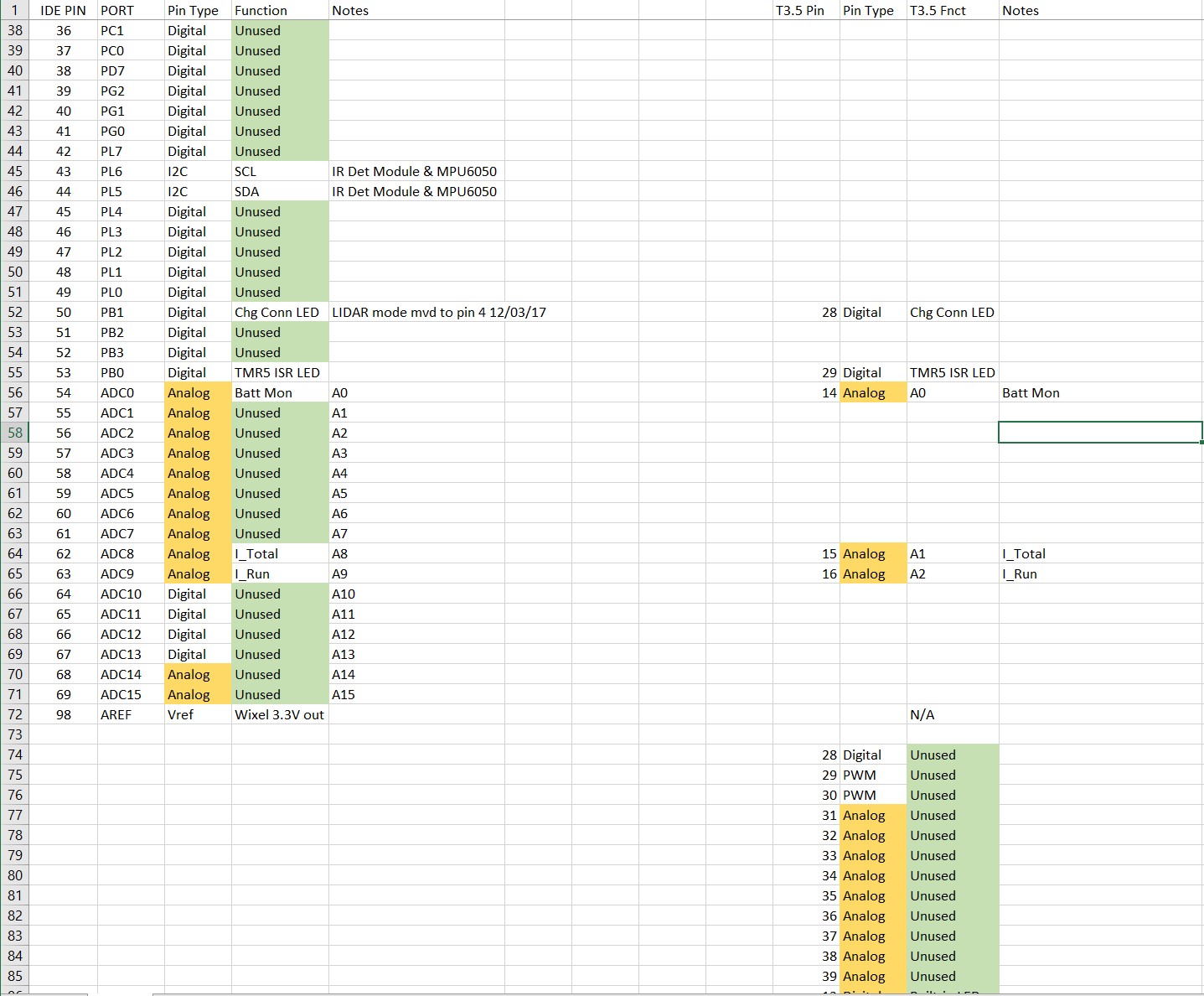
#pragma region PIN ASSIGNMENTS
//vvvvvvvvvvvvvvvvvvvvvvvvvvvvvvvvvvvvvvvvvvvvvvvvvvvvvvvvvvvvvv//
//=================== START PIN ASSIGNMENTS ===================//
//vvvvvvvvvvvvvvvvvvvvvvvvvvvvvvvvvvvvvvvvvvvvvvvvvvvvvvvvvvvvvv//
#pragma region MOTOR_PINS
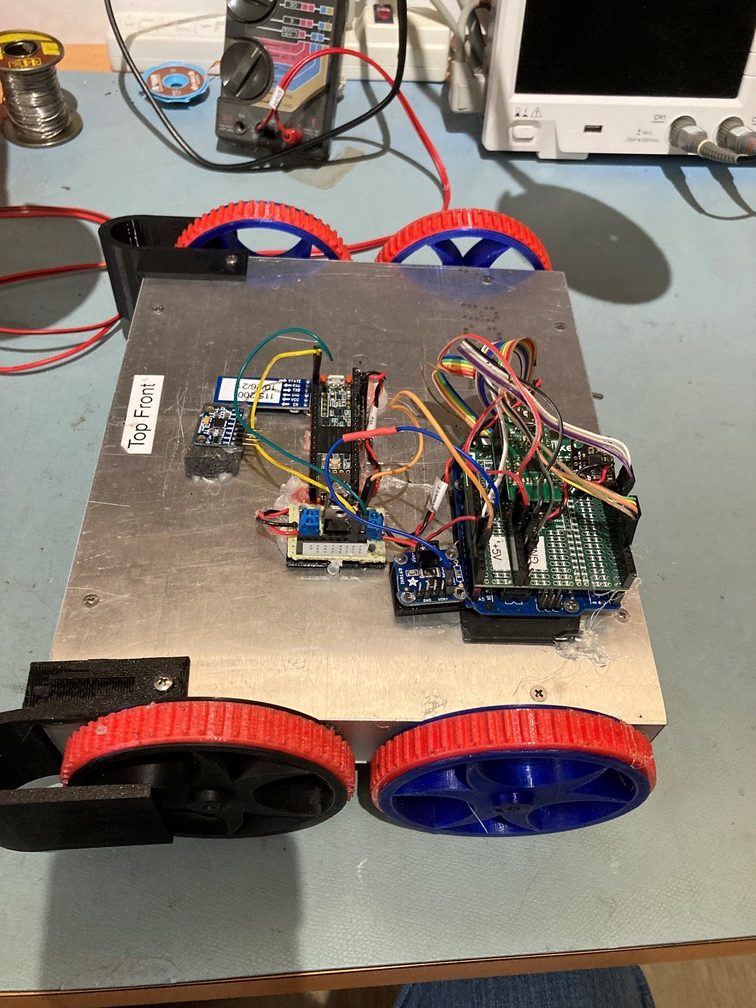
//11/04/21 Now using Pololu VNH5019 drivers for all 4 motors
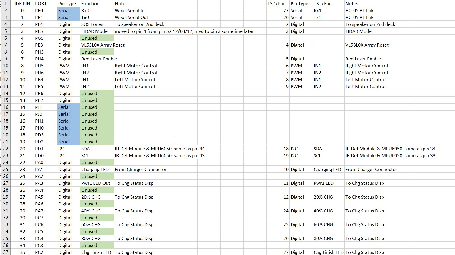
const int InA_Left = 22;
const int InB_Left = 21;
const int Spd_Left = 23;
const int InA_Right = 34;
const int InB_Right = 33;
const int Spd_Right = 35;
#pragma endregion Motor Pin Assignments
const int ChgConnectPin = 36;
const int ItotPin = A1;
const int IRunPin = A2;
const int BATT_MON_PIN = A0;
#pragma endregion PIN ASSIGNMENTS
#pragma region MOTOR_PARAMETERS
//drive wheel speed parameters
const int MOTOR_SPEED_FULL = 200; //range is 0-255
const int MOTOR_SPEED_MAX = 255; //range is 0-255
const int MOTOR_SPEED_HALF = 127; //range is 0-255
const int MOTOR_SPEED_QTR = 75; //added 09/25/20
const int MOTOR_SPEED_LOW = 50; //added 01/22/15
const int MOTOR_SPEED_OFF = 0; //range is 0-255
const int MOTOR_SPEED_CAPTURE_OFFSET = 75; //added 06/21/20 for offset capture
const int TURN_START_SPEED = MOTOR_SPEED_QTR; //added 11/14/21
//drive wheel direction constants
const boolean FWD_DIR = true;
const boolean REV_DIR = !FWD_DIR;
const bool TURNDIR_CCW = true;
const bool TURNDIR_CW = false;
//Motor direction variables
bool bIsForwardDir = true; //default is foward direction
#pragma endregion Motor Parameters
#pragma region MPU6050_SUPPORT
uint8_t mpuIntStatus; // holds actual interrupt status byte from MPU. Used in Homer's Overflow routine
uint8_t devStatus; // return status after each device operation (0 = success, !0 = error)
uint16_t packetSize; // expected DMP packet size (default is 42 bytes)
uint16_t fifoCount; // count of all bytes currently in FIFO
uint8_t fifoBuffer[64]; // FIFO storage buffer
// orientation/motion vars
Quaternion q; // [w, x, y, z] quaternion container
VectorInt16 aa; // [x, y, z] accel sensor measurements
VectorInt16 aaReal; // [x, y, z] gravity-free accel sensor measurements
VectorInt16 aaWorld; // [x, y, z] world-frame accel sensor measurements
VectorFloat gravity; // [x, y, z] gravity vector
float euler[3]; // [psi, theta, phi] Euler angle container
float ypr[3]; // [yaw, pitch, roll] yaw/pitch/roll container and gravity vector
int GetPacketLoopCount = 0;
int OuterGetPacketLoopCount = 0;
//MPU6050 status flags
bool bMPU6050Ready = true;
bool dmpReady = false; // set true if DMP init was successful
volatile float IMUHdgValDeg = 0; //updated by UpdateIMUHdgValDeg()//11/02/20 now updated in ISR
const uint16_t MAX_GETPACKET_LOOPS = 100; //10/30/19 added for backup loop exit condition in GetCurrentFIFOPacket()
uint8_t GetCurrentFIFOPacket(uint8_t* data, uint8_t length, uint16_t max_loops = MAX_GETPACKET_LOOPS); //prototype here so can define a default param
bool bFirstTime = true;
//#define MPU6050_CCW_INCREASES_YAWVAL //added 12/05/19 commented out 11/22/21 as now the MPU6050 module is mounted 'Z-up'
#pragma endregion MPU6050 Support
#pragma region HEADING_AND_RATE_BASED_TURN_PARAMETERS
elapsedMillis MsecSinceLastTurnRateUpdate;
const int MAX_SPIN_MOTOR_SPEED = 250;
const int MIN_SPIN_MOTOR_SPEED = 50;
const int TURN_RATE_UPDATE_INTERVAL_MSEC = 30; //30 mSec is as fast as it can go
double TurnRateOutput;
double TurnRateSetPoint_DPS;
double Ival = 0;
double lastErr = 0;
double lastTurnRateVal_DPS;
double TurnRateVal_DPS;
double Prev_HdgDeg = 0;
float tgt_deg;
float timeout_sec;
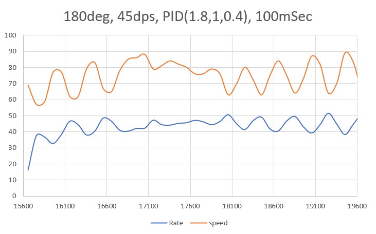
//11/16/21 almost perfect for 45 deg/sec, 100mSec
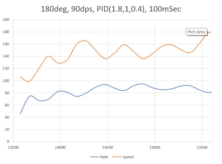
//11/17/21 and pretty good for 90 deg/sec too!
double TurnRate_Kp = 1.8;
double TurnRate_Ki = 1.0;
double TurnRate_Kd = 0.4;
//ported from FourWD_PulseTurnRateTest.ino
double TurnRatePIDOutput;
//06/02/
const float HDG_NEAR_MATCH_VAL = 0.8; //slow the turn down here
const float HDG_FULL_MATCH_VAL = 0.99; //stop the turn here //rev 06/01/21
const float HDG_MIN_MATCH_VAL = 0.6; //added 09/08/18: don't start checking slope until turn is well started
#pragma endregion HEADING_AND_RATE_BASED_TURN_PARAMETERS
#pragma region OTA UPDATE
//******************************************************************************
// hex_info_t struct for hex record and hex file info
//******************************************************************************
typedef struct { //
char* data; // pointer to array allocated elsewhere
unsigned int addr; // address in intel hex record
unsigned int code; // intel hex record type (0=data, etc.)
unsigned int num; // number of data bytes in intel hex record
uint32_t base; // base address to be added to intel hex 16-bit addr
uint32_t min; // min address in hex file
uint32_t max; // max address in hex file
int eof; // set true on intel hex EOF (code = 1)
int lines; // number of hex records received
} hex_info_t;
void read_ascii_line(Stream* serial, char* line, int maxbytes);
int parse_hex_line(const char* theline, char* bytes,
unsigned int* addr, unsigned int* num, unsigned int* code);
int process_hex_record(hex_info_t* hex);
void update_firmware(Stream* serial, uint32_t buffer_addr, uint32_t buffer_size);
uint32_t buffer_addr, buffer_size; //09/20/21 copied from FlasherX - loop()
#pragma endregion OTA UPDATE
#pragma endregion PRE_SETUP
void setup()
{
Serial.begin(115200);
delay(2000); //10/06/21 - just use fixed delay instead
Serial1.begin(115200); //used HC-05 'AT' commands to set this speed
//while (!Serial1) {}
delay(2000); //11/20/21 use fixed delay instead of waiting
Wire.begin(I2C_MASTER, 0x00, I2C_PINS_18_19, I2C_PULLUP_EXT, 400000);
//DEBUG!!
if (Serial)
{
Serial.printf("Serial = %p, Serial1 = %p\n", &Serial, &Serial1);
}
//DEBUG!!
//
//DEBUG!!
if (Serial1)
{
Serial.printf("Serial = %p, Serial1 = %p\n", &Serial, &Serial1);
}
//DEBUG!!
#pragma region PIN INITIALIZATION
pinMode(LED_BUILTIN, OUTPUT);
pinMode(ItotPin, INPUT); //I_total 1V/Amp
pinMode(BATT_MON_PIN, INPUT); //Battery voltage monitor
//motor pins
pinMode(InA_Left, OUTPUT);
pinMode(InB_Left, OUTPUT);
pinMode(Spd_Left, OUTPUT);
pinMode(InA_Right, OUTPUT);
pinMode(InB_Right, OUTPUT);
pinMode(Spd_Right, OUTPUT);
#pragma endregion PIN INITIALIZATION
#pragma region MPU6050
Serial.printf("\nChecking for MPU6050 IMU at I2C Addr 0x%x\n", MPU6050_I2C_ADDR);
mpu.initialize();
// verify connection
Serial.println(mpu.testConnection() ? F("MPU6050 connection successful") : F("MPU6050 connection failed"));
float StartSec = 0; //used to time MPU6050 init
Serial.println(F("Initializing DMP..."));
devStatus = mpu.dmpInitialize();
// make sure it worked (returns 0 if successful)
if (devStatus == 0)
{
// turn on the DMP, now that it's ready
Serial.println(F("Enabling DMP..."));
mpu.setDMPEnabled(true);
// set our DMP Ready flag so the main loop() function knows it's okay to use it
Serial.println(F("DMP ready! Waiting for MPU6050 drift rate to settle..."));
dmpReady = true;
// get expected DMP packet size for later comparison
packetSize = mpu.dmpGetFIFOPacketSize();
Serial.printf("Just after MPU6050 Init\n");
Serial.printf("Calibrating...\n");
mpu.CalibrateGyro(); //using default value of 15
Serial.printf("Retrieving Calibration Values\n\n");
mpu.PrintActiveOffsets();
//loop heading display until stabilized
Serial.printf("\nMsec\tHdg\n");
UpdateIMUHdgValDeg();
Prev_HdgDeg = IMUHdgValDeg;
delay(100);
UpdateIMUHdgValDeg();
Serial.printf("%lu\t%2.3f\t%2.3f\n", millis(), IMUHdgValDeg, Prev_HdgDeg);
while (abs(IMUHdgValDeg - Prev_HdgDeg) > 0.1f)
{
Serial.printf("%lu\t%2.3f\n", millis(), IMUHdgValDeg);
Prev_HdgDeg = IMUHdgValDeg;
delay(100);
UpdateIMUHdgValDeg();
}
StartSec = millis() / 1000.f;
Serial.printf("MPU6050 Ready at %2.2f Sec with delta = %2.3f\n", StartSec, IMUHdgValDeg - Prev_HdgDeg);
bMPU6050Ready = true;
delay(1000);
}
else //MPU6050 Init failed for some reason
{
// ERROR!
// 1 = initial memory load failed
// 2 = DMP configuration updates failed
// (if it's going to break, usually the code will be 1)
Serial.print(F("DMP Initialization failed (code "));
Serial.print(devStatus);
Serial.println(F(")"));
//08/29/21 print out battery voltage on failure
float batV = GetBattVoltage();
Serial.printf("Battery Voltage = %2.2f\n", batV);
bMPU6050Ready = false;
}
#pragma endregion MPU6050
analogReadAveraging(4); //applies to all analogRead() operations?
MsecSinceLastLEDToggle = 0;
Serial1.printf("Msec\tBattV\tTotAmps\tRunAmps\tHdgDeg\n");
}
void loop()
{
//if (Serial1.available())
if (Serial1.available()||Serial.available())
{
CheckForUserInput();
}
if (MsecSinceLastLEDToggle >= 200)
{
MsecSinceLastLEDToggle -= 200;
digitalWrite(LED_BUILTIN, !digitalRead(LED_BUILTIN));
//11/01/21 read I_tot value & cvt to current
int ItotVal = analogRead(ItotPin);
double ItotVolts = ItotVal * VoltsPerCount;
double ItotAmps = ItotVolts * AmpsPerVolt;
//Get battery voltage
float calc_volts = GetBattVoltage();
//print out battery voltage & charge current
Serial1.printf("%lu\t%2.2f\t%2.2f\n", millis(), calc_volts, ItotAmps);
Serial.printf("%lu\t%2.2f\t%2.2f\n", millis(), calc_volts, ItotAmps);
}
}
float GetBattVoltage()
{
//02/18/17 get corrected battery voltage. Voltage reading is 1/3 actual Vbatt value
//int analog_batt_reading = GetAverageAnalogReading(BATT_MON_PIN, VOLTS_AVERAGE_NUMBER);//rev 03/01/19 to average readings
int analog_batt_reading = analogRead(BATT_MON_PIN);//analogReadAveraging(4) in setup() does internal averaging
float calc_volts = ZENER_VOLTAGE_OFFSET + ADC_REF_VOLTS * (double)analog_batt_reading / (double)MAX_AD_COUNT;
////DEBUG!!
// Serial1.printf("a/d = %d, calc = %2.2f\n", analog_batt_reading,calc_volts);
////DEBUG!!
return calc_volts;
}
//void CheckForUserInput()
//{
// //Notes:
// // 11/21/21 rev to accomodate cmd input from either serial, and output to both
//
// const int bufflen = 80;
// char buff[bufflen];
// memset(buff, 0, bufflen);
// float OffsetCm;
// float Kp, Ki, Kd;
// const char s[2] = ",";
// char* token;
// byte incomingByte = 0; //moved here 11/21/21
//
// if (Serial.available() > 0)
// {
// // read the incoming byte:
// //int incomingByte = Serial.read();
// incomingByte = Serial.read();
//
// // say what you got:
// Serial.print("I received: ");
// Serial.println(incomingByte, HEX); //chg to HEX 02/18/20
// }
//
// //11/21/21 now input can come from Serial1 too
// else if (Serial1.available() > 0)
// {
// // read the incoming byte:
// incomingByte = Serial1.read();
//
// // say what you got:
// Serial1.print("I received: ");
// Serial1.println(incomingByte, HEX); //chg to HEX 02/18/20
// }
//
// //11/21/21 incomingByte can come from either serial input
// if (incomingByte != 0)
// {
// //02/18/20 experiment with multiple commands
// switch (incomingByte)
// {
// case 0x55: //ASCII 'U'
// case 0x75: //ASCII 'u'
//#pragma region FIRMWARE UPDATE
// Serial1.println(F("Start Program Update - Send new HEX file!"));
//
//
// //09/20/21 copied from FlasherX - loop()
// if (firmware_buffer_init(&buffer_addr, &buffer_size) == 0)
// {
// Serial1.printf("unable to create buffer\n");
// Serial1.flush();
// for (;;) {}
// }
//
// Serial1.printf("buffer = %1luK %s (%08lX - %08lX)\n",
// buffer_size / 1024, IN_FLASH(buffer_addr) ? "FLASH" : "RAM",
// buffer_addr, buffer_addr + buffer_size);
//
// //09/20/21 clear the serial buffer
// while (Serial1.available())
// {
// Serial1.read();
// }
//
// // receive hex file via serial, write new firmware to flash, clean up, reboot
// update_firmware(&Serial1, buffer_addr, buffer_size); // no return if success
//
// // return from update_firmware() means error or user abort, so clean up and
// // reboot to ensure that static vars get boot-up initialized before retry
// Serial1.printf("erase FLASH buffer / free RAM buffer...\n");
// firmware_buffer_free(buffer_addr, buffer_size);
// Serial1.flush();
// REBOOT;
// break;
//#pragma endregion FIRMWARE UPDATE
// case 0x43: //ASCII 'C'
// case 0x63: //ASCII 'c'
//#pragma region MANUALCONTROL
// //enter infinite loop for direct remote control
// Serial.println(F("ENTERING COMMAND MODE:"));
// Serial.println(F("0 = 180 deg CCW Turn"));
// Serial.println(F("1 = 180 deg CW Turn"));
// Serial.println(F("A = Back to Auto Mode"));
// Serial.println(F("S = Stop"));
// Serial.println(F("F = Forward"));
// Serial.println(F("R = Reverse"));
// Serial.println(F(""));
// Serial.println(F(" Faster"));
// Serial.println(F("\t8"));
// Serial.println(F("Left 4\t5 6 Right"));
// Serial.println(F("\t2"));
// Serial.println(F(" Slower"));
//
// Serial1.println(F("ENTERING COMMAND MODE:"));
// Serial1.println(F("0 = 180 deg CCW Turn"));
// Serial1.println(F("1 = 180 deg CW Turn"));
// Serial1.println(F("A = Back to Auto Mode"));
// Serial1.println(F("S = Stop"));
// Serial1.println(F("F = Forward"));
// Serial1.println(F("R = Reverse"));
// Serial1.println(F(""));
// Serial1.println(F(" Faster"));
// Serial1.println(F("\t8"));
// Serial1.println(F("Left 4\t5 6 Right"));
// Serial1.println(F("\t2"));
// Serial1.println(F(" Slower"));
//
// StopBothMotors();
// int speed = 0;
//
// bool bAutoMode = false;
// while (!bAutoMode)
// {
// if (Serial.available() > 0)
// {
// // read the incoming byte:
// incomingByte = Serial.read();
//
// // say what you got:
// Serial.print("I received: ");
// Serial.println(incomingByte, HEX); //chg to HEX 02/18/20
// }
//
// //11/21/21 now input can come from Serial1 too
// else if (Serial1.available() > 0)
// {
// // read the incoming byte:
// incomingByte = Serial1.read();
//
// // say what you got:
// Serial1.print("I received: ");
// Serial1.println(incomingByte, HEX); //chg to HEX 02/18/20
// }
//
// //11/21/21 incomingByte can come from either serial input
// if (incomingByte != 0)
// {
// switch (incomingByte)
// {
// case 0x30: //Dec '0'
// Serial.println(F("CCW 180 deg Turn"));
// Serial1.println(F("CCW 180 deg Turn"));
// SpinTurn(true, 180, 90);
// MoveAhead(speed, speed);
// break;
// case 0x31: //Dec '1'
// Serial.println(F("CW 180 deg Turn"));
// Serial1.println(F("CW 180 deg Turn"));
// SpinTurn(false, 180, 45);
// break;
// case 0x34: //Turn left 10 deg and keep moving
// Serial.println(F("CCW 10 deg Turn"));
// Serial1.println(F("CCW 10 deg Turn"));
// SpinTurn(true, 10, 30);
//
// if (bIsForwardDir)
// {
// MoveAhead(speed, speed);
// }
// else
// {
// MoveReverse(speed, speed);
// }
// break;
// case 0x36: //Turn right 10 deg and keep moving
// Serial.print("CW 10 deg Turn\n");
// Serial1.print("CW 10 deg Turn\n");
// SpinTurn(false, 10, 30);
//
// //added 05/03/20
// if (bIsForwardDir)
// {
// MoveAhead(speed, speed);
// }
// else
// {
// MoveReverse(speed, speed);
// }
// break;
// case 0x38: //Speed up
// speed += 50;
// speed = (speed >= MOTOR_SPEED_MAX) ? MOTOR_SPEED_MAX : speed;
// Serial.printf("Speeding up: speed now %d\n", speed);
// Serial1.printf("Speeding up: speed now %d\n", speed);
// if (bIsForwardDir)
// {
// MoveAhead(speed, speed);
// }
// else
// {
// MoveReverse(speed, speed);
// }
// break;
// case 0x32: //Slow down
// speed -= 50;
// speed = (speed < 0) ? 0 : speed;
// Serial.printf("Slowing down: speed now %d\n", speed);
// Serial1.printf("Slowing down: speed now %d\n", speed);
// if (bIsForwardDir)
// {
// MoveAhead(speed, speed);
// }
// else
// {
// MoveReverse(speed, speed);
// }
// break;
// case 0x35: //05/07/20 changed to use '5' vs 'S'
// Serial.println(F("Stopping Motors!"));
// Serial1.println(F("Stopping Motors!"));
// StopBothMotors();
// speed = 0;
// break;
// case 0x41: //ASCII 'A'
// case 0x61: //ASCII 'a'
// StopBothMotors();
// Serial.println(F("Re-entering AUTO mode"));
// Serial1.println(F("Re-entering AUTO mode"));
// bAutoMode = true;
// break;
// case 0x52: //ASCII 'R'
// case 0x72: //ASCII 'r'
// Serial.println(F("Setting both motors to reverse"));
// Serial1.println(F("Setting both motors to reverse"));
// bIsForwardDir = false;
// //MoveReverse(speed, speed);
// break;
// case 0x46: //ASCII 'F'
// case 0x66: //ASCII 'f'
// Serial.println(F("Setting both motors to forward"));
// Serial1.println(F("Setting both motors to forward"));
// bIsForwardDir = true;
// MoveAhead(speed, speed);
//#pragma endregion MANUALCONTROL
// break;
//
//#pragma region WALL OFFSET TRACKING CASES
// //left side wall tracking
// case 0x4C: //ASCII 'L'
// case 0x6C: //ASCII 'l'
// StopBothMotors();
// Serial.println(F("Setting Kp value"));
//
// //consume CR/LF chars
// while (Serial.available() > 0)
// {
// int byte = Serial.read();
// Serial.printf("consumed %d\n", byte);
// }
//
// while (!Serial.available())
// {
// }
//
// Serial.readBytes(buff, bufflen);
// Serial.printf("%s\n", buff);
//
// /* extract Kp */
// token = strtok(buff, s);
// Kp = atof(token);
//
// /* extract Ki */
// token = strtok(NULL, s);
// Ki = atof(token);
//
// /* extract Kd */
// token = strtok(NULL, s);
// Kd = atof(token);
//
// /* extract Offset in cm */
// token = strtok(NULL, s);
// OffsetCm = atof(token);
//
// Serial.printf("Kp,Ki,Kd,OffsetCm = %2.2f, %2.2f, %2.2f, %2.2f\n",
// Kp, Ki, Kd, OffsetCm);
//
// //TrackLeftWallOffset(Kp, Ki, Kd, OffsetCm);
// break;
// case 0x4D: //ASCII 'M'
// case 0x6D: //ASCII 'm'
// StopBothMotors();
// Serial.println(F("Setting Kp value"));
//
// //consume CR/LF chars
// while (Serial.available() > 0)
// {
// int byte = Serial.read();
// Serial.printf("consumed %d\n", byte);
// }
//
// while (!Serial.available())
// {
// }
//
// Serial.readBytes(buff, bufflen);
// Serial.printf("%s\n", buff);
//
// /* extract Kp */
// token = strtok(buff, s);
// Kp = atof(token);
//
// /* extract Ki */
// token = strtok(NULL, s);
// Ki = atof(token);
//
// /* extract Kd */
// token = strtok(NULL, s);
// Kd = atof(token);
//
// /* extract Offset in cm */
// token = strtok(NULL, s);
// OffsetCm = atof(token);
//
// Serial.printf("Kp,Ki,Kd,OffsetCm = %2.2f, %2.2f, %2.2f, %2.2f\n",
// Kp, Ki, Kd, OffsetCm);
//
// //TrackRightWallOffset(Kp, Ki, Kd, OffsetCm);
// break;
//#pragma endregion WALL OFFSET TRACKING CASES
// default:
// Serial.println(F("In Default Case: Stopping Motors!"));
// Serial1.println(F("In Default Case: Stopping Motors!"));
// StopBothMotors();
// while (true)
// {
//
// }
// }
// }
// }
// }
// }
//}
void CheckForUserInput()
{
//Notes:
// 11/21/21 rev to accomodate cmd input from either serial, and output to both
const int bufflen = 3;
char buff[bufflen];
memset(buff, 0, bufflen);
byte incomingByte = 0; //moved here 11/21/21
int numchars = 0;
if (Serial.available() > 0)
{
// read the incoming byte:
//incomingByte = Serial.read();
numchars = Serial.readBytesUntil('\n', buff, sizeof(buff));
incomingByte = buff[0];
// say what you got:
Serial.printf("I received %d chars, first char 0X%X on Serial\n", numchars, incomingByte);
}
//11/21/21 now input can come from Serial1 too
else if (Serial1.available() > 0)
{
// read the incoming byte:
//incomingByte = Serial1.read();
numchars = Serial1.readBytesUntil('\n', buff, sizeof(buff));
incomingByte = buff[0];
// say what you got:
Serial1.printf("I received %d chars, first char 0X%X on Serial1\n", numchars, incomingByte);
}
//11/21/21 incomingByte can come from either serial input
if (incomingByte != 0)
{
//02/18/20 experiment with multiple commands
switch (incomingByte)
{
case 0x55: //ASCII 'U'
case 0x75: //ASCII 'u'
#pragma region FIRMWARE UPDATE
Serial1.println(F("Start Program Update - Send new HEX file!"));
//09/20/21 copied from FlasherX - loop()
if (firmware_buffer_init(&buffer_addr, &buffer_size) == 0)
{
Serial1.printf("unable to create buffer\n");
Serial1.flush();
for (;;) {}
}
Serial1.printf("buffer = %1luK %s (%08lX - %08lX)\n",
buffer_size / 1024, IN_FLASH(buffer_addr) ? "FLASH" : "RAM",
buffer_addr, buffer_addr + buffer_size);
//09/20/21 clear the serial buffer
while (Serial1.available())
{
Serial1.read();
}
// receive hex file via serial, write new firmware to flash, clean up, reboot
update_firmware(&Serial1, buffer_addr, buffer_size); // no return if success
// return from update_firmware() means error or user abort, so clean up and
// reboot to ensure that static vars get boot-up initialized before retry
Serial1.printf("erase FLASH buffer / free RAM buffer...\n");
firmware_buffer_free(buffer_addr, buffer_size);
Serial1.flush();
REBOOT;
break;
#pragma endregion FIRMWARE UPDATE
case 0x43: //ASCII 'C'
case 0x63: //ASCII 'c'
#pragma region MANUALCONTROL
//enter infinite loop for direct remote control
Serial.println(F("ENTERING COMMAND MODE:"));
Serial.println(F("0 = 180 deg CCW Turn"));
Serial.println(F("1 = 180 deg CW Turn"));
Serial.println(F("A = Back to Auto Mode"));
Serial.println(F("S = Stop"));
Serial.println(F("F = Forward"));
Serial.println(F("R = Reverse"));
Serial.println(F(""));
Serial.println(F(" Faster"));
Serial.println(F("\t8"));
Serial.println(F("Left 4\t5 6 Right"));
Serial.println(F("\t2"));
Serial.println(F(" Slower"));
Serial1.println(F("ENTERING COMMAND MODE:"));
Serial1.println(F("0 = 180 deg CCW Turn"));
Serial1.println(F("1 = 180 deg CW Turn"));
Serial1.println(F("A = Back to Auto Mode"));
Serial1.println(F("S = Stop"));
Serial1.println(F("F = Forward"));
Serial1.println(F("R = Reverse"));
Serial1.println(F(""));
Serial1.println(F(" Faster"));
Serial1.println(F("\t8"));
Serial1.println(F("Left 4\t5 6 Right"));
Serial1.println(F("\t2"));
Serial1.println(F(" Slower"));
StopBothMotors();
int speed = 0;
bool bAutoMode = false;
while (Serial.available())
{
incomingByte = Serial.read();
//Serial.printf("I removed 0X%X from Serial\n",incomingByte);
}
while (Serial1.available())
{
incomingByte = Serial1.read();
//Serial1.printf("I removed 0X%X from Serial1\n", incomingByte);
}
incomingByte = 0;
while (!bAutoMode)
{
if (Serial.available() > 0)
{
// read the incoming bytes:
numchars = Serial.readBytesUntil('\n', buff, sizeof(buff));
incomingByte = buff[0];
// say what you got:
Serial.printf("I received %d chars, first char 0X%X on Serial\n", numchars, incomingByte);
while (Serial.available())
{
Serial.read();
Serial.printf("I removed 0X%X from Serial\n",incomingByte);
}
}
//11/21/21 now input can come from Serial1 too
else if (Serial1.available() > 0)
{
// read the incoming bytes:
numchars = Serial1.readBytesUntil('\n', buff, sizeof(buff));
incomingByte = buff[0];
// say what you got:
Serial1.printf("I received %d chars, first char 0X%X on Serial1\n", numchars, incomingByte);
while (Serial1.available())
{
Serial1.read();
Serial1.printf("I removed 0X%X from Serial1\n", incomingByte);
}
}
//11/21/21 incomingByte can come from either serial input
if (incomingByte != 0)
{
switch (incomingByte)
{
case 0x30: //Dec '0'
Serial.println(F("CCW 180 deg Turn"));
Serial1.println(F("CCW 180 deg Turn"));
SpinTurn(true, 180, 90);
MoveAhead(speed, speed);
break;
case 0x31: //Dec '1'
Serial.println(F("CW 180 deg Turn"));
Serial1.println(F("CW 180 deg Turn"));
SpinTurn(false, 180, 45);
break;
case 0x34: //Turn left 10 deg and keep moving
Serial.println(F("CCW 10 deg Turn"));
Serial1.println(F("CCW 10 deg Turn"));
SpinTurn(true, 10, 30);
if (bIsForwardDir)
{
MoveAhead(speed, speed);
}
else
{
MoveReverse(speed, speed);
}
break;
case 0x36: //Turn right 10 deg and keep moving
Serial.print("CW 10 deg Turn\n");
Serial1.print("CW 10 deg Turn\n");
SpinTurn(false, 10, 30);
//added 05/03/20
if (bIsForwardDir)
{
MoveAhead(speed, speed);
}
else
{
MoveReverse(speed, speed);
}
break;
case 0x38: //Speed up
speed += 50;
speed = (speed >= MOTOR_SPEED_MAX) ? MOTOR_SPEED_MAX : speed;
Serial.printf("Speeding up: speed now %d\n", speed);
Serial1.printf("Speeding up: speed now %d\n", speed);
if (bIsForwardDir)
{
MoveAhead(speed, speed);
}
else
{
MoveReverse(speed, speed);
}
break;
case 0x32: //Slow down
speed -= 50;
speed = (speed < 0) ? 0 : speed;
Serial.printf("Slowing down: speed now %d\n", speed);
Serial1.printf("Slowing down: speed now %d\n", speed);
if (bIsForwardDir)
{
MoveAhead(speed, speed);
}
else
{
MoveReverse(speed, speed);
}
break;
case 0x35: //05/07/20 changed to use '5' vs 'S'
Serial.println(F("Stopping Motors!"));
Serial1.println(F("Stopping Motors!"));
StopBothMotors();
speed = 0;
break;
case 0x41: //ASCII 'A'
case 0x61: //ASCII 'a'
StopBothMotors();
Serial.println(F("Re-entering AUTO mode"));
Serial1.println(F("Re-entering AUTO mode"));
bAutoMode = true;
break;
case 0x52: //ASCII 'R'
case 0x72: //ASCII 'r'
Serial.println(F("Setting both motors to reverse"));
Serial1.println(F("Setting both motors to reverse"));
bIsForwardDir = false;
//MoveReverse(speed, speed);
break;
case 0x46: //ASCII 'F'
case 0x66: //ASCII 'f'
Serial.println(F("Setting both motors to forward"));
Serial1.println(F("Setting both motors to forward"));
bIsForwardDir = true;
MoveAhead(speed, speed);
#pragma endregion MANUALCONTROL
break;
default:
Serial.println(F("In Default Case: Stopping Motors!"));
Serial1.println(F("In Default Case: Stopping Motors!"));
StopBothMotors();
//while (true)
//{
//}
}
incomingByte = 0;
}
}
}
}
}
#pragma region MOTOR SUPPORT
//09/08/20 modified for DRV8871 motor driver
void MoveReverse(int leftspeednum, int rightspeednum)
{
//Purpose: Move in reverse direction continuously - companion to MoveAhead()
//ProvEnA_Pinnce: G. Frank Paynter 09/08/18
//Inputs:
// leftspeednum = integer denoting speed (0=stop, 255 = full speed)
// rightspeednum = integer denoting speed (0=stop, 255 = full speed)
//Outputs: both drive Motors energized with the specified speed
//Plan:
// Step 1: Set reverse direction for both wheels
// Step 2: Run both Motors at specified speeds
//Notes:
// 01/22/20 now using Adafruit DRV8871 drivers
//Step 1: Set reverse direction and speed for both wheels
SetLeftMotorDirAndSpeed(REV_DIR, leftspeednum);
SetRightMotorDirAndSpeed(REV_DIR, rightspeednum);
}
//09/08/20 modified for DRV8871 motor driver
void MoveAhead(int leftspeednum, int rightspeednum)
{
//Purpose: Move ahead continuously
//ProvEnA_Pinnce: G. Frank Paynter and Danny Frank 01/24/2014
//Inputs:
// leftspeednum = integer denoting speed (0=stop, 255 = full speed)
// rightspeednum = integer denoting speed (0=stop, 255 = full speed)
//Outputs: both drive Motors energized with the specified speed
//Plan:
// Step 1: Set forward direction for both wheels
// Step 2: Run both Motors at specified speeds
//Notes:
// 01/22/20 now using Adafruit DRV8871 drivers
//Serial1.printf("InMoveAhead(%d,%d)\n", leftspeednum, rightspeednum);
//Step 1: Set forward direction and speed for both wheels
SetLeftMotorDirAndSpeed(true, leftspeednum);
SetRightMotorDirAndSpeed(true, rightspeednum);
}
//09/08/20 modified for DRV8871 motor driver
//11/04/21 modified for Pololu VNH5019 motor driver
void StopLeftMotors()
{
digitalWrite(InA_Left, LOW);
digitalWrite(InB_Left, LOW);
analogWrite(Spd_Left, MOTOR_SPEED_OFF);
}
//11/04/21 modified for Pololu VNH5019 motor driver
void StopRightMotors()
{
digitalWrite(InA_Right, LOW);
digitalWrite(InB_Right, LOW);
analogWrite(Spd_Right, MOTOR_SPEED_OFF);
}
//09/08/20 added bool bisFwd param for DRV8871 motor driver
void RunBothMotors(bool bisFwd, int leftspeednum, int rightspeednum)
{
//Purpose: Run both Motors at left/rightspeednum speeds
//Inputs:
// speednum = speed value (0 = OFF, 255 = full speed)
//Outputs: Both Motors run for timesec seconds at speednum speed
//Plan:
// Step 1: Apply drive to both wheels
//Notes:
// 01/14/15 - added left/right speed offset for straightness compensation
// 01/22/15 - added code to restrict fast/slow values
// 01/24/15 - revised for continuous run - no timing
// 01/26/15 - speednum modifications moved to UpdateWallFollowmyMotorspeeds()
// 12/07/15 - chg args from &int to int
//Step 1: Apply drive to both wheels
//DEBUG!!
//Serial1.printf("In RunBothMotors(%s, %d,%d)\n", bisFwd? "FWD":"REV", leftspeednum, rightspeednum);
//DEBUG!!
SetLeftMotorDirAndSpeed(bisFwd, leftspeednum);
SetRightMotorDirAndSpeed(bisFwd, rightspeednum);
}
void RunBothMotorsBidirectional(int leftspeed, int rightspeed)
{
//Purpose: Accommodate the need for independent bidirectional wheel motion
//Inputs:
// leftspeed - integer denoting left wheel speed. Positive value is fwd, negative is rev
// rightspeed - integer denoting right wheel speed. Positive value is fwd, negative is rev
//Outputs:
// left/right wheel motors direction and speed set as appropriate
//Plan:
// Step1: Set left wheel direction and speed
// Step2: Set right wheel direction and speed
//Step1: Set left wheel direction and speed
//DEBUG!!
//Serial1.printf("In RunBothMotorsBidirectional(%d, %d)\n", leftspeed, rightspeed);
if (leftspeed < 0)
{
SetLeftMotorDirAndSpeed(false, -leftspeed); //neg value ==> reverse
}
else
{
SetLeftMotorDirAndSpeed(true, leftspeed); //pos or zero value ==> fwd
}
//Step2: Set right wheel direction and speed
if (rightspeed < 0)
{
SetRightMotorDirAndSpeed(false, -rightspeed); //neg value ==> reverse
}
else
{
SetRightMotorDirAndSpeed(true, rightspeed); //pos or zero value ==> fwd
}
}
//09/08/20 added bool bisFwd param for DRV8871 motor driver
void RunBothMotorsMsec(bool bisFwd, int timeMsec, int leftspeednum, int rightspeednum)
{
//Purpose: Run both Motors for timesec seconds at speednum speed
//Inputs:
// timesec = time in seconds to run the Motors
// speednum = speed value (0 = OFF, 255 = full speed)
//Outputs: Both Motors run for timesec seconds at speednum speed
//Plan:
// Step 1: Apply drive to both wheels
// Step 2: Delay timsec seconds
// Step 3: Remove drive from both wheels.
//Notes:
// 01/14/15 - added left/right speed offset for straightness compensation
// 01/22/15 - added code to restrict fast/slow values
// 11/25/15 - rev to use motor driver class object
// 09/08/20 added bool bisFwd param for DRV8871 motor driver
RunBothMotors(bisFwd, leftspeednum, rightspeednum);
//Step 2: Delay timsec seconds
delay(timeMsec);
//Step3: Stop motors added 04/12/21
StopBothMotors();
}
//11/25/15 added for symmetry ;-).
void StopBothMotors()
{
StopLeftMotors();
StopRightMotors();
}
void SetLeftMotorDirAndSpeed(bool bIsFwd, int speed)
{
//DEBUG!!
//Serial.printf("In SetLeftMotorDirAndSpeed(%s, %d)\n",
// (bIsFwd == true) ? "true" : "false", speed);
//Serial1.printf("In SetLeftMotorDirAndSpeed(%s, %d)\n",
// (bIsFwd == true) ? "true" : "false", speed);
//DEBUG!!
//11/04/21 fwd for right motors is CCW when looking at shaft
#ifndef NO_MOTORS
if (bIsFwd)
{
digitalWrite(InA_Left, LOW);
digitalWrite(InB_Left, HIGH);
analogWrite(Spd_Left, speed);
//DEBUG!!
//Serial.printf("In TRUE block of SetLeftMotorDirAndSpeed(%s, %d)\n",
// (bIsFwd == true) ? "true" : "false", speed);
//Serial1.printf("In TRUE block of SetLeftMotorDirAndSpeed(%s, %d)\n",
// (bIsFwd == true) ? "true" : "false", speed);
//DEBUG!!
}
else
{
//DEBUG!!
//Serial.printf("In FALSE block of SetLeftMotorDirAndSpeed(%s, %d)\n",
// (bIsFwd == true) ? "true" : "false", speed);
//Serial1.printf("In FALSE block of SetLeftMotorDirAndSpeed(%s, %d)\n",
// (bIsFwd == true) ? "true" : "false", speed);
//DEBUG!!
digitalWrite(InA_Left, HIGH);
digitalWrite(InB_Left, LOW);
analogWrite(Spd_Left, speed);
}
#endif // !NO_MOTORS
}
void SetRightMotorDirAndSpeed(bool bIsFwd, int speed)
{
//DEBUG!!
//Serial.printf("In SetRightMotorDirAndSpeed(%s, %d)\n",
// (bIsFwd == true) ? "true" : "false", speed);
//Serial1.printf("In SetRightMotorDirAndSpeed(%s, %d)\n",
// (bIsFwd == true) ? "true" : "false", speed);
//DEBUG!!
//11/04/21 fwd for right motors is CW when looking at shaft
#ifndef NO_MOTORS
if (bIsFwd)
{
//DEBUG!!
//Serial.printf("In TRUE block of SetRighttMotorDirAndSpeed(%s, %d)\n",
// (bIsFwd == true) ? "true" : "false", speed);
//Serial1.printf("In TRUE block of SetRighttMotorDirAndSpeed(%s, %d)\n",
// (bIsFwd == true) ? "true" : "false", speed);
//DEBUG!!
digitalWrite(InA_Right, HIGH);
digitalWrite(InB_Right, LOW);
analogWrite(Spd_Right, speed);
}
else
{
//DEBUG!!
//Serial.printf("In FALSE block of SetRightMotorDirAndSpeed(%s, %d)\n",
// (bIsFwd == true) ? "true" : "false", speed);
//Serial1.printf("In FALSE block of SetRightMotorDirAndSpeed(%s, %d)\n",
// (bIsFwd == true) ? "true" : "false", speed);
//DEBUG!!
digitalWrite(InA_Right, LOW);
digitalWrite(InB_Right, HIGH);
analogWrite(Spd_Right, speed);
}
#endif // !NO_MOTORS
}
#pragma endregion Motor Support Functions
#pragma region HDG_BASED_TURN_SUPPORT
bool SpinTurn(bool b_ccw, float numDeg, float degPersec) //04/25/21 added turn-rate arg (default = TURN_RATE_TARGET_DEGPERSEC)
{
//Purpose: Make a numDeg CW or CCW 'spin' turn
//Inputs:
// b_ccw - True if turn is to be ccw, false otherwise
// numDeg - angle to be swept out in the turn
// ROLLING_TURN_MAX_SEC_PER_DEG = const used to generate timeout proportional to turn deg
// IMUHdgValDeg = IMU heading value updated by UpdateIMUHdgValDeg() //11/02/20 now updated in ISR
// degPerSec = float value denoting desired turn rate
//Plan:
// Step1: Get current heading as starting point
// Step2: Disable TIMER5 interrupts
// Step3: Compute new target value & timeout value
// Step4: Run motors until target reached, using inline PID algorithm to control turn rate
// Step5: Re-enable TIMER5 interrupts
//Notes:
// 06/06/21 we-written to remove PID library - now uses custom 'PIDCalcs()' function
// 06/06/21 added re-try for 180.00 return from IMU - could be bad value
// 06/11/21 added code to correct dHdg errors due to 179/-179 transition & bad IMU values
// 06/12/21 cleaned up & commented out debug code
// 11/14/21 removed 'first time skip' block; added motor start before entering loop
float tgt_deg;
float timeout_sec;
bool bDoneTurning = false;
bool bTimedOut = false;
bool bResult = true; //04/21/20 added so will be only one exit point
//DEBUG!!
Serial.printf("In SpinTurn(%s, %2.2f, %2.2f)\n", b_ccw == TURNDIR_CCW ? "CCW" : "CW", numDeg, degPersec);
Serial1.printf("In SpinTurn(%s, %2.2f, %2.2f)\n", b_ccw == TURNDIR_CCW ? "CCW" : "CW", numDeg, degPersec);
//Serial.printf("TurnRatePID started with Kp/Ki/Kd = %2.1f,%2.1f,%2.1f, SampleTime(mSec) = %d\n",
//TurnRate_Kp, TurnRate_Ki, TurnRate_Kd, TURN_RATE_UPDATE_INTERVAL_MSEC);
//DEBUG!!
//no need to continue if the IMU isn't available
if (!dmpReady)
{
Serial.printf("DMP Failure - returning FALSE\n");
return false;
}
//Step1: Get current heading as starting point
//06/06/21 it is possible for IMU to return 180.00 on failure
//so try again. If it really IS 180, then
//it will eventually time out and go on
//08/26/21 re-wrote using 3-value array to make sure initial heading is a steady value
UpdateIMUHdgValDeg();
int retries = 0;
if ((IMUHdgValDeg == 180.f || IMUHdgValDeg == 0.f) && retries < 5)
{
//DEBUG!!
Serial.printf("Got 180.00 or 0.00 exactly (%2.3f) from IMU - retrying %d...\n", IMUHdgValDeg, retries);
Serial1.printf("Got 180.00 or 0.00 exactly (%2.3f) from IMU - retrying %d...\n", IMUHdgValDeg, retries);
//DEBUG!!
UpdateIMUHdgValDeg();
retries++;
delay(100);
}
//Step2: Compute new target value & timeout value
//timeout_sec = 3 * numDeg / degPersec; //05/29/21 rev to use new turn rate parmeter
timeout_sec = 2 * numDeg / degPersec; //05/29/21 rev to use new turn rate parmeter
//05/17/20 limit timeout_sec to 1 sec or more
timeout_sec = (timeout_sec < 1) ? 1.f : timeout_sec;
//12/05/19 added #define back in to manage which direction increases yaw values
#ifdef MPU6050_CCW_INCREASES_YAWVAL
tgt_deg = b_ccw ? IMUHdgValDeg + numDeg : IMUHdgValDeg - numDeg;
#else
tgt_deg = b_ccw ? IMUHdgValDeg - numDeg : IMUHdgValDeg + numDeg;
#endif // MPU6050_CCW_INCREASES_YAWVAL
//correct for -180/180 transition
if (tgt_deg < -180)
{
tgt_deg += 360;
}
//07/29/19 bugfix
if (tgt_deg > 180)
{
tgt_deg -= 360;
}
//DEBUG!!
Serial.printf("Init hdg = %4.2f deg, Turn = %4.2f deg, tgt = %4.2f deg, timeout = %4.2f sec\n\n",
IMUHdgValDeg, numDeg, tgt_deg, timeout_sec);
Serial1.printf("Init hdg = %4.2f deg, Turn = %4.2f deg, tgt = %4.2f deg, timeout = %4.2f sec\n\n",
IMUHdgValDeg, numDeg, tgt_deg, timeout_sec);
//DEBUG!!
float curHdgMatchVal = 0;
//09/08/18 added to bolster end-of-turn detection
float prevHdgMatchVal = 0;
float matchSlope = 0;
//Step3: Run motors until target reached, using PID algorithm to control turn rate
Prev_HdgDeg = IMUHdgValDeg; //06/10/21 synch Prev_HdgDeg & IMUHdgValDeg just before entering loop
//11/14/21 start motors before entering loop. For CCW turn, left motors go backwards, right ones forward
int startSpd = (degPersec <= 45) ? TURN_START_SPEED : 2 * TURN_START_SPEED;
SetLeftMotorDirAndSpeed(!b_ccw, startSpd);
SetRightMotorDirAndSpeed(b_ccw, startSpd);
elapsedMillis sinceLastTimeCheck = 0;
elapsedMillis sinceLastComputeTime = 0;
double lastError = 0;
double lastInput = 0;
double lastIval = 0;
double lastDerror = 0;
//bool bFirstIMUHdg = true;
//DEBUG!!
Serial.printf("Msec\tHdg\tPrvHdg\tdHdg\tRate\ttgtDPS\terr\tKp*err\tIval\tKd*Derr\tspeed\tMatch\tSlope\n");
Serial1.printf("Msec\tHdg\tPrvHdg\tdHdg\tRate\ttgtDPS\terr\tKp*err\tIval\tKd*Derr\tspeed\tMatch\tSlope\n");
//DEBUG!!
while (!bDoneTurning && !bTimedOut)
{
//11/06/20 now just loops between PID calcs
CheckForUserInput();
if (sinceLastComputeTime >= TURN_RATE_UPDATE_INTERVAL_MSEC)
{
sinceLastComputeTime -= TURN_RATE_UPDATE_INTERVAL_MSEC;
UpdateIMUHdgValDeg(); //update IMUHdgValDeg
double dHdg = IMUHdgValDeg - Prev_HdgDeg;
if (dHdg > 180)
{
dHdg -= 360;
//Serial.printf("dHdg > 180 - subtracting 360\n");
}
else if (dHdg < -180)
{
dHdg += 360;
//Serial.printf("dHdg < -180 - adding 360\n");
}
//watch for turn rates that are wildly off
double rate = abs(1000 * dHdg / TURN_RATE_UPDATE_INTERVAL_MSEC);
//if (rate > 3 * degPersec)
//{
// //DEBUG!!
// Serial.printf("hdg/prevhdg/dHdg/rate = %2.2f\t%2.2f\t%2.2f\t%2.2f, excessive rate - replacing with %2.2f\n", IMUHdgValDeg, Prev_HdgDeg, dHdg, rate, degPersec);
// //DEBUG!!
// rate = degPersec;
//}
TurnRatePIDOutput = PIDCalcs(rate, degPersec, TURN_RATE_UPDATE_INTERVAL_MSEC, lastError, lastInput, lastIval, lastDerror, TurnRate_Kp, TurnRate_Ki, TurnRate_Kd);
int speed = 0;
(TurnRatePIDOutput > MOTOR_SPEED_MAX) ? speed = MOTOR_SPEED_MAX : speed = (int)TurnRatePIDOutput;
(TurnRatePIDOutput <= MOTOR_SPEED_LOW) ? speed = MOTOR_SPEED_LOW : speed = (int)TurnRatePIDOutput;
SetLeftMotorDirAndSpeed(!b_ccw, speed);
SetRightMotorDirAndSpeed(b_ccw, speed);
//check for nearly there and all the way there
curHdgMatchVal = GetHdgMatchVal(tgt_deg, IMUHdgValDeg);
matchSlope = curHdgMatchVal - prevHdgMatchVal;
Serial.printf("%lu\t%2.2f\t%2.2f\t%2.2f\t%2.2f\t%2.2f\t%2.2f\t%2.2f\t%2.2f\t%2.2f\t%d\t%2.2f\t%2.2f\n",
millis(),
IMUHdgValDeg,
Prev_HdgDeg,
dHdg,
rate,
degPersec,
lastError,
TurnRate_Kp * lastError,
lastIval,
TurnRate_Kd * lastDerror,
speed,
curHdgMatchVal,
matchSlope);
Serial1.printf("%lu\t%2.2f\t%2.2f\t%2.2f\t%2.2f\t%2.2f\t%2.2f\t%2.2f\t%2.2f\t%2.2f\t%d\t%2.2f\t%2.2f\n",
millis(),
IMUHdgValDeg,
Prev_HdgDeg,
dHdg,
rate,
degPersec,
lastError,
TurnRate_Kp * lastError,
lastIval,
TurnRate_Kd * lastDerror,
speed,
curHdgMatchVal,
matchSlope);
//DEBUG!!
Prev_HdgDeg = IMUHdgValDeg; //re-synch prev to curr hdg for next time
//look for full match
bDoneTurning = (curHdgMatchVal >= HDG_FULL_MATCH_VAL
|| (prevHdgMatchVal >= HDG_MIN_MATCH_VAL && matchSlope <= -0.01)); //have to use < vs <= as slope == 0 at start
//Serial.printf("curHdgMatchVal = %2.2f, prevHdgMatchVal = %2.2f, matchslope = %2.2f, bDoneTurning = %d\n",
// curHdgMatchVal,
// prevHdgMatchVal,
// matchSlope,
// bDoneTurning);
prevHdgMatchVal = curHdgMatchVal; //07/31/21 moved below bDoneTurning chk so can use prevHdgMatchVal vs curHdgMatchVal in slope check
bTimedOut = (sinceLastTimeCheck > timeout_sec * 1000);
if (bTimedOut)
{
//DEBUG!!
Serial.printf("timed out with yaw = %3.2f, tgt = %3.2f, and match = %1.3f\n", IMUHdgValDeg, tgt_deg, curHdgMatchVal);
Serial1.printf("timed out with yaw = %3.2f, tgt = %3.2f, and match = %1.3f\n", IMUHdgValDeg, tgt_deg, curHdgMatchVal);
//DEBUG!!
bResult = false;
break;
}
if (bDoneTurning)
{
Serial.printf("Completed turn with yaw = %3.2f, tgt = %3.2f, and match = %1.3f\n", IMUHdgValDeg, tgt_deg, curHdgMatchVal);
Serial1.printf("Completed turn with yaw = %3.2f, tgt = %3.2f, and match = %1.3f\n", IMUHdgValDeg, tgt_deg, curHdgMatchVal);
bResult = true;
break;
}
}
}
StopBothMotors();
delay(1000); //added 04/27/21 for debug
return bResult;
}
double PIDCalcs(double input, double setpoint, uint16_t sampleTime, double& lastError, double& lastInput, double& lastIval, double& lastDerror, double Kp, double Ki, double Kd)
{
//Purpose: Encapsulate PID algorithm so can get rid of PID library. Library too cumbersome and won't synch with TIMER5 ISR
//Inputs:
// input = double denoting current input value (turn rate, speed, whatever)
// setpoint = double denoting desired setpoint in same units as input
// sampleTime = int denoting sample time to be used in calcs.
// lastError = ref to double denoting error saved from prev calc
// lastInput = ref to double denoting input saved from prev calc
// Kp/Ki/Kd = doubles denoting PID values to be used for calcs
// Output = ref to double denoting output from calc
double error = setpoint - input;
//double dInput = (input - lastInput);
//lastIval += (error);
lastIval += (Ki * error);
//11/16/21 rev to clamp integral term
lastIval = (lastIval > MOTOR_SPEED_MAX) ? MOTOR_SPEED_MAX : lastIval;
lastIval = (lastIval < MOTOR_SPEED_OFF) ? MOTOR_SPEED_OFF : lastIval;
double dErr = (error - lastError);
//Serial.printf("PIDCalcs: error/dInput/lastIval/dErr/kp/ki/kd = %2.2f\t%2.2f\t%2.2f\t%2.2f\t%2.2f\t%2.2f\t%2.2f\n", error, dInput, lastIval, dErr,
// Kp,Ki,Kd);
/*Compute PID Output*/
//11/16/21 rev to subtract differential term rather than add.
//double output = Kp * error + Ki * lastIval + Kd * dErr;
double output = Kp * error + lastIval - Kd * dErr;
//11/16/21 now clamping output value as well as I term
output = (output > MOTOR_SPEED_MAX) ? MOTOR_SPEED_MAX : output;
output = (output < MOTOR_SPEED_OFF) ? MOTOR_SPEED_OFF : output;
/*Remember some variables for next time*/
lastError = error;
lastInput = input;
lastDerror = dErr;
return output; //added 09/03/21
}
float GetHdgMatchVal(float tgt_deg, float cur_deg)
{
//Purpose: Compute the match ratio between two compass headings
//Inputs:
// tgt_deg = float representing target heading in +/-180 range
// IMUHdgValDeg = float representing sensor yaw value in +/-180 deg range
//Outputs:
// returns result of 1 - abs(Tgt_deg - Hdg_deg)/180, all angles in 0-360 deg range
//Plan:
// Step1: convert both inputs to 0-360 deg range
// Step2: compute match ratio
//Notes:
// formula from https://gis.stackexchange.com/questions/129954/comparing-compass-bearings
//Step1: convert both inputs to 0-360 deg range
float tgthdg = (tgt_deg < 0) ? tgt_deg + 360 : tgt_deg;
float curhdg = (cur_deg < 0) ? cur_deg + 360 : cur_deg;
//Step2: compute match ratio
float match_ratio = 1 - abs(tgthdg - curhdg) / 180;
//DEBUG!!
//Serial1.printf("tgt\tcur\tmatch = %4.2f\t%4.2f\t%1.3f\n", tgthdg, curhdg, match_ratio);
//DEBUG!!
return abs(match_ratio);
}
float UpdateIMUHdgValDeg()
{
//Purpose: Get latest yaw (heading) value from IMU
//Inputs: None. This function should only be called after mpu.dmpPacketAvailable() returns TRUE
//Outputs:
// returns true if successful, otherwise false
// IMUHdgValDeg updated on success
//Plan:
//Step1: check for overflow and reset the FIFO if it occurs. In this case, wait for new packet
//Step2: read all available packets to get to latest data
//Step3: update IMUHdgValDeg with latest value
//Notes:
// 10/08/19 changed return type to boolean
// 10/08/19 no longer need mpuIntStatus
// 10/21/19 completely rewritten to use Homer's algorithm
// 05/05/20 changed return type to float vs bool.
int flag = GetCurrentFIFOPacket(fifoBuffer, packetSize, MAX_GETPACKET_LOOPS); //get the latest mpu packet
if (flag != 0) //0 = error exit, 1 = normal exit, 2 = recovered from an overflow
{
// display Euler angles in degrees
mpu.dmpGetQuaternion(&q, fifoBuffer);
mpu.dmpGetGravity(&gravity, &q);
mpu.dmpGetYawPitchRoll(ypr, &q, &gravity);
//compute the yaw value
IMUHdgValDeg = ypr[0] * 180 / M_PI;
}
return IMUHdgValDeg;//05/05/20 now returns updated value for use convenience
}
uint8_t GetCurrentFIFOPacket(uint8_t* data, uint8_t length, uint16_t max_loops)
{
mpu.resetFIFO();
delay(1);
//int countloop = 0;
fifoCount = mpu.getFIFOCount();
GetPacketLoopCount = 0;
//Serial1.printf("In GetCurrentFIFOPacket: before loop fifoC = %d\t", fifoCount);
while (fifoCount < packetSize && GetPacketLoopCount < max_loops)
{
GetPacketLoopCount++;
fifoCount = mpu.getFIFOCount();
delay(2);
}
//Serial1.printf("In GetCurrentFIFOPacket: after loop fifoC = %d, loop count = %d\n", fifoCount, GetPacketLoopCount);
if (GetPacketLoopCount >= max_loops)
{
return 0;
}
//if we get to here, there should be exactly one packet in the FIFO
mpu.getFIFOBytes(data, packetSize);
return 1;
}
//void BackupAndTurn90Deg(bool b_ccw, bool b_fwd, int motor_speed)
//{
// //Purpose: Backup 1 second and then turn 90 degrees
// //Provenance: G. Frank Paynter 06/27/2020
// //Inputs:
// // bIsCCW = bool denoting direction for the turn
// // bIsFwd = bool denoting fwd/bkwd direction for the turn
// // motor_speed = int denoting motor speed to use for the maneuver
// //Outputs:
// // Robot backs up 1 sec, then turns 90 deg in the specified direction
// //Plan:
// // Step1: Back up for 1 sec
// // Step2: Turn 90 deg in specified direction
// //Notes:
// // 06/27/20 Replaces BackupAndTurn in all Tracking modes
// //10/13/20 rev to terminate backup at Wall Offset Distance
//
////Step1: Back up for 1 sec
// BackupSignal(true); //turn backup LEDs ON
// MoveReverse(MOTOR_SPEED_HALF, MOTOR_SPEED_HALF);
// //delay(1000);
//
// //10/13/20 rev to terminate backup at Wall Offset Distance
// while (frontdistval < WALL_OFFSET_TGTDIST_CM && !bIsStuck)
// {
// if (bTimeForNavUpdate) //wait for next ISR hit
// {
// bTimeForNavUpdate = false;
// Serial.print(F("BackupAndTurn90Deg: ")); Serial1.printf("%lu\t% d\n", millis(), frontdistval);
// }
// }
// BackupSignal(false);//turn them back OFF
//
// //Serial1.printf("BackupAndTurn90Deg terminated with frontdist = %d\n", frontdistval);
// Serial.print(F("BackupAndTurn90Deg terminated with frontdist = ")); Serial1.printf("%d\n", frontdistval);
//
// //Step2: Turn 90 deg fwd or backward in specified direction
// SpinTurn(b_ccw, 90); //06/27/20 experiment
//}
#pragma endregion HDG_BASED_TURN_SUPPORT
#pragma region FLASHER_X
//09/20/21 copied from FlasherX
//******************************************************************************
// update_firmware() read hex file and write new firmware to program flash
//******************************************************************************
void update_firmware(Stream* serial, uint32_t buffer_addr, uint32_t buffer_size)
{
static char line[96]; // buffer for hex lines
static char data[32] __attribute__((aligned(8))); // buffer for hex data
hex_info_t hex = { // intel hex info struct
data, 0, 0, 0, // data,addr,num,code
0, 0xFFFFFFFF, 0, // base,min,max,
0, 0 // eof,lines
};
serial->printf("waiting for hex lines...\n");
// read and process intel hex lines until EOF or error
//DEBUG!!
//int line_num = 0;
//DEBUG!!
long int start_msec = 0;
bool bFirstTime = true;
while (!hex.eof) {
read_ascii_line(serial, line, sizeof(line));
if (bFirstTime)
{
start_msec = millis();
bFirstTime = false;
}
//DEBUG!!
//serial->printf("%d: %s\n", line_num, line);
//line_num++;
//DEBUG!!
//10/02/21 gfp added for visual xfer confirmation
if (hex.lines % 10 == 0)
{
digitalWriteFast(LED_BUILTIN, !digitalReadFast(LED_BUILTIN));
}
// reliability of transfer via USB is improved by this printf/flush
if (serial == (Stream*)&Serial)
{
serial->printf("%s\n", line);
serial->flush();
}
if (parse_hex_line((const char*)line, hex.data, &hex.addr, &hex.num, &hex.code) == 0) {
serial->printf("abort - bad hex line %s\n", line);
return;
}
else if (process_hex_record(&hex) != 0) { // error on bad hex code
serial->printf("abort - invalid hex code %d\n", hex.code);
return;
}
else if (hex.code == 0) { // if data record
uint32_t addr = buffer_addr + hex.base + hex.addr - FLASH_BASE_ADDR;
if (hex.max > (FLASH_BASE_ADDR + buffer_size)) {
serial->printf("abort - max address %08lX too large\n", hex.max);
return;
}
else if (!IN_FLASH(buffer_addr)) {
memcpy((void*)addr, (void*)hex.data, hex.num);
}
else if (IN_FLASH(buffer_addr)) {
int error = flash_write_block(addr, hex.data, hex.num);
if (error) {
serial->printf("abort - error %02X in flash_write_block()\n", error);
return;
}
}
}
hex.lines++;
}
//serial->printf("\nhex file: %1d lines %1lu bytes (%08lX - %08lX)\n",
// hex.lines, hex.max - hex.min, hex.min, hex.max);
serial->printf("\nhex file: %1d lines %1lu bytes (%08lX - %08lX), %lu Msec\n",
hex.lines, hex.max - hex.min, hex.min, hex.max, millis() - start_msec);
// check FSEC value in new code -- abort if incorrect
#if defined(KINETISK) || defined(KINETISL)
uint32_t value = *(uint32_t*)(0x40C + buffer_addr);
if (value == 0xfffff9de) {
serial->printf("new code contains correct FSEC value %08lX\n", value);
}
else {
serial->printf("abort - FSEC value %08lX should be FFFFF9DE\n", value);
return;
}
#endif
// check FLASH_ID in new code - abort if not found
if (check_flash_id(buffer_addr, hex.max - hex.min)) {
serial->printf("new code contains correct target ID %s\n", FLASH_ID);
}
else {
serial->printf("abort - new code missing string %s\n", FLASH_ID);
return;
}
// get user input to write to flash or abort
int user_lines = -1;
while (user_lines != hex.lines && user_lines != 0) {
serial->printf("enter %d to flash or 0 to abort\n", hex.lines);
read_ascii_line(serial, line, sizeof(line));
sscanf(line, "%d", &user_lines);
}
if (user_lines == 0) {
serial->printf("abort - user entered 0 lines\n");
return;
}
// move new program from buffer to flash, free buffer, and reboot
//serial->printf("user entered %d lines\n", user_lines);
flash_move(FLASH_BASE_ADDR, buffer_addr, hex.max - hex.min);
// should not return from flash_move(), but put REBOOT here as reminder
REBOOT;
}
//******************************************************************************
// read_ascii_line() read ascii characters until '\n', '\r', or max bytes
//******************************************************************************
void read_ascii_line(Stream* serial, char* line, int maxbytes)
{
int c = 0, nchar = 0;
while (nchar < maxbytes && !(c == '\n' || c == '\r')) {
if (serial->available()) {
c = serial->read();
line[nchar++] = c;
}
}
line[nchar - 1] = 0; // null-terminate
}
//******************************************************************************
// process_hex_record() process record and return okay (0) or error (1)
//******************************************************************************
int process_hex_record(hex_info_t* hex)
{
if (hex->code == 0) { // data -- update min/max address so far
if (hex->base + hex->addr + hex->num > hex->max)
hex->max = hex->base + hex->addr + hex->num;
if (hex->base + hex->addr < hex->min)
hex->min = hex->base + hex->addr;
}
else if (hex->code == 1) { // EOF (:flash command not received yet)
hex->eof = 1;
}
else if (hex->code == 2) { // extended segment address (top 16 of 24-bit addr)
hex->base = ((hex->data[0] << 8) | hex->data[1]) << 4;
}
else if (hex->code == 3) { // start segment address (80x86 real mode only)
return 1;
}
else if (hex->code == 4) { // extended linear address (top 16 of 32-bit addr)
hex->base = ((hex->data[0] << 8) | hex->data[1]) << 16;
}
else if (hex->code == 5) { // start linear address (32-bit big endian addr)
hex->base = (hex->data[0] << 24) | (hex->data[1] << 16)
| (hex->data[2] << 8) | (hex->data[3] << 0);
}
else {
return 1;
}
return 0;
}
//******************************************************************************
// Intel Hex record foramt:
//
// Start code: one character, ASCII colon ':'.
// Byte count: two hex digits, number of bytes (hex digit pairs) in data field.
// Address: four hex digits
// Record type: two hex digits, 00 to 05, defining the meaning of the data field.
// Data: n bytes of data represented by 2n hex digits.
// Checksum: two hex digits, computed value used to verify record has no errors.
//
// Examples:
// :10 9D30 00 711F0000AD38000005390000F5460000 35
// :04 9D40 00 01480000 D6
// :00 0000 01 FF
//******************************************************************************
/* Intel HEX read/write functions, Paul Stoffregen, paul@ece.orst.edu */
/* This code is in the public domain. Please retain my name and */
/* email address in distributed copies, and let me know about any bugs */
/* I, Paul Stoffregen, give no warranty, expressed or implied for */
/* this software and/or documentation provided, including, without */
/* limitation, warranty of merchantability and fitness for a */
/* particular purpose. */
// type modifications by Jon Zeeff
/* parses a line of intel hex code, stores the data in bytes[] */
/* and the beginning address in addr, and returns a 1 if the */
/* line was valid, or a 0 if an error occured. The variable */
/* num gets the number of bytes that were stored into bytes[] */
#include <stdio.h> // sscanf(), etc.
#include <string.h> // strlen(), etc.
int parse_hex_line(const char* theline, char* bytes,
unsigned int* addr, unsigned int* num, unsigned int* code)
{
unsigned sum, len, cksum;
const char* ptr;
int temp;
*num = 0;
if (theline[0] != ':')
return 0;
if (strlen(theline) < 11)
return 0;
ptr = theline + 1;
if (!sscanf(ptr, "%02x", &len))
return 0;
ptr += 2;
if (strlen(theline) < (11 + (len * 2)))
return 0;
if (!sscanf(ptr, "%04x", (unsigned int*)addr))
return 0;
ptr += 4;
/* Serial1.printf("Line: length=%d Addr=%d\n", len, *addr); */
if (!sscanf(ptr, "%02x", code))
return 0;
ptr += 2;
sum = (len & 255) + ((*addr >> 8) & 255) + (*addr & 255) + (*code & 255);
while (*num != len)
{
if (!sscanf(ptr, "%02x", &temp))
return 0;
bytes[*num] = temp;
ptr += 2;
sum += bytes[*num] & 255;
(*num)++;
if (*num >= 256)
return 0;
}
if (!sscanf(ptr, "%02x", &cksum))
return 0;
if (((sum & 255) + (cksum & 255)) & 255)
return 0; /* checksum error */
return 1;
}
#pragma endregion FLASHER_X