Author Archives: paynterf

Better Battery Charging for Wall-E2

Posted 08 February 2019,

After recovering from my bout with #include file hell, I’m back to working on Wall-E2, my autonomous wall-following robot.  In a previous post I described the integration of the TP5100 charger module into Wall-E2’s system, but I have lately discovered that the TP5100 end-of-charge (EOC) detection scheme isn’t very reliable in my application.  The TP5100 uses a current threshold to determine EOC, which works fine in a normal application where the battery pack isn’t simultaneously supplying current to the load, but in my application, Wall-E2 stays active and alert while it’s docked at it’s feeding station; it has to, in order to be able to respond to the EOC signal and detach itself.  So, the current going through the TP5100 never goes below the idling current for Wall-E2, which is on the order of 300mA or so.  This is enough to keep the charging current above the TP5100 EOC threshold, and so Wall-E2 hangs on to the charging station forever – not what I had in mind!

Life would be good if I somehow measure Wall-E2’s idling current while on charge and the total charging current.  Then I could subtract the two values to get the excess current, i.e. the current going into the battery but not coming out – the current actually going into increasing the battery charge level. When this current falls below an appropriate threshold, then charging could be terminated. This scenario is complicated by the need to measure the current on the high side of the charging circuit and of the +Vbatt supply to the rest of the system.

Well, as it turns out, Adafruit (and I’m sure others) makes a high-side current sensor just for this purpose, based on the 1NA219 and INA169 chips. The INA219 module reports current via an I2C connection, while the 1NA169 module provides a open-emitter current source proportional to the current through an onboard 0.1Ω resistor (see this data sheet for details).  My plan is to use two of these modules; one at the charging circuit input, and a second one at the 8.4V +VBatt supply from the battery to the rest of the system. Since Wall-E2 stays awake during charging, it should be simple to monitor both currents and decide when charging is complete (or complete enough, anyway).  As a bonus, I should be able to extend the life of Wall-E2’s battery pack by terminating the charge at less than 100% capacity. See this very informative post by François Boucher for the details.

03 March 2019 Update:

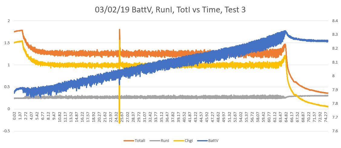
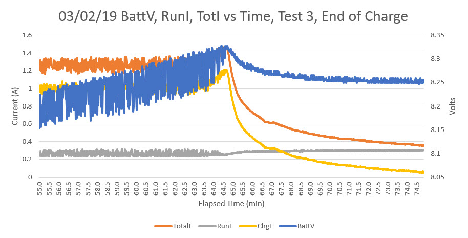
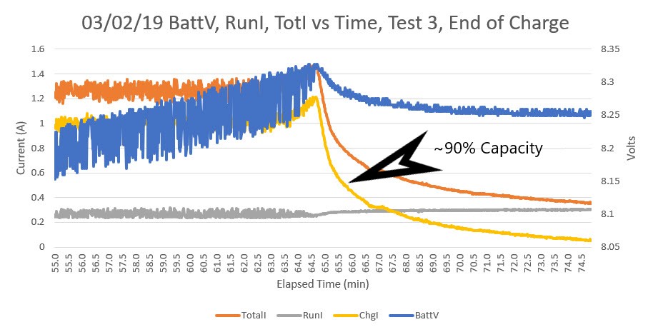
After the usual number of mistakes and setbacks, I think I have the dual current sensor feature working, and now WallE-2 charges by monitoring both the battery voltage and the actual charging current (total current measured at the charging connector minus the run current measured on WallE-2’s main power line).  As a final test, I discharged the main battery pack at about 1A for about 1 hour, and then charged it again using the two-current method. As shown in the Excel plots below, Charging terminated when the actual battery charging current fell below 50mA.

Complete charge cycle, after discharging at approx 1A for approx 1 Hr

Last 20 minutes or so of charge operation, showing detail of end-of-charge behavior

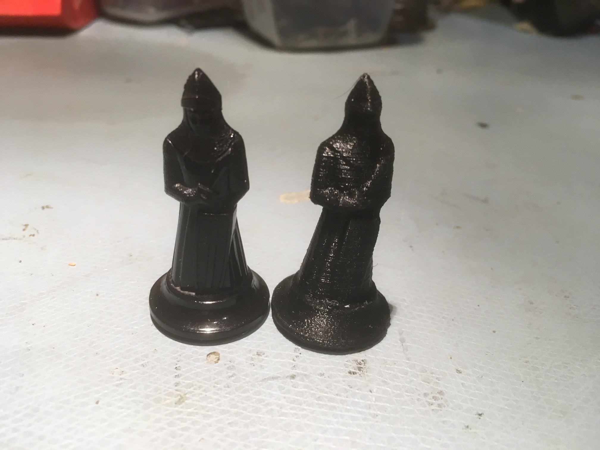
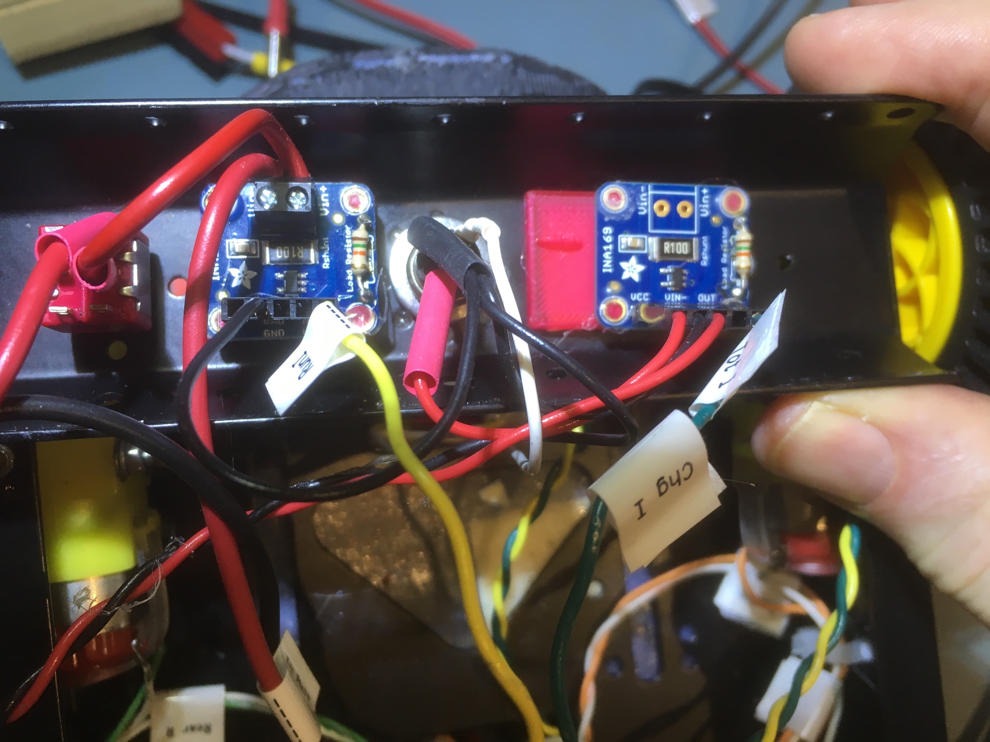
two 1NA169 high-side current sensors mounted in the battery/motor compartment.  Note the 3D-printed mounting plates.

Here is a showing the installation of the two 1NA169 sensor modules in WallE-2’s battery compartment.  The one on the left measures running current, and the one on the right measures total current (charging + running).

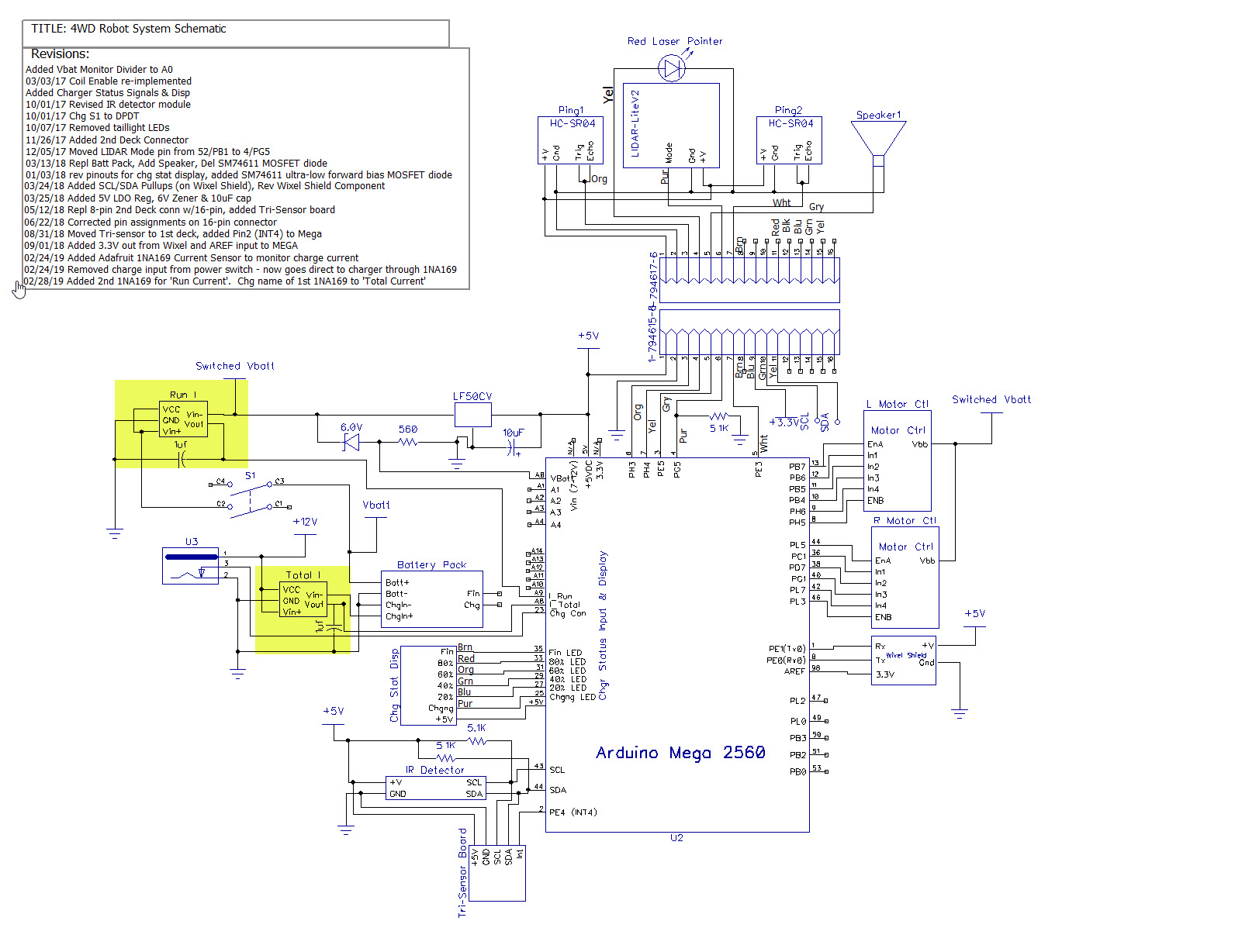
The following figure shows the system schematic for WallE-2, with the two new 1NA169 sensors highlighted

System schematic with locations of new current sensors highlighted

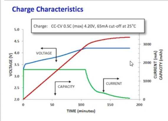
Now that I have the current sensors and the new charge algorithm working, it’s time to go back an take another look at the charge/discharge characteristics of the Panasonic 18650B cells I’m using to see if I can extend their life with a more intelligent charge/discharge scheme.  The following plot shows the charge characteristics for this cell.

Charge plot for the Panasonic 18650B LiPo cell

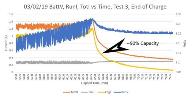
As noted by François Boucher, the red line above is the total energy returned to the battery during charge.  As he notes, the battery acquires about 90% of its total capacity in the first 105 minutes of the charge period, when charged at 0.5C at 25C.  My battery pack is a 2-cell parallel x 2-cell series stack, and currently I’m charging to a 50mA cutoff.  According to Boucher, this is way too low – I’m charging to almost 100% capacity and thereby limiting the cycle life of the battery pack.  Looking at the end-of-charge detail plot above (repeated below), I should probably use a charge current threshold of around 500mA charging current (250mA per cell in the parallel stack) for about 90% capacity charge.

End-of-charge detail with approximate 90% charge current highlighted

On the discharge side, Panasonic’s Discharge Characteristics plot below shows a discharge down to 2.50V/cell.  WallE-2’s typical current drain is about 1A or about 0.3 – 0.5C, and the cutoff I’m using is 3.0V cell.  From the plot, this gives about 3150mAH of the approximately 3300mAH available at 0.5C, or about 95%.  So, it looks like I should raise the discharge cutoff voltage to about 3.2V or about 3000mAH of the 3300mAH available, or about 90%.

Conclusion:

So revisiting WallE-2’s battery management seems to have paid off; I now have much better visibility into and control over charge/discharge of the 18650B battery pack, and at least some expectation that I can use WallE-2’s new found battery super powers for good rather than evil ;-).

Stay tuned!

Frank


Back to the future with Wall-E2. Wall-following Part II

Posted 09 February 2019

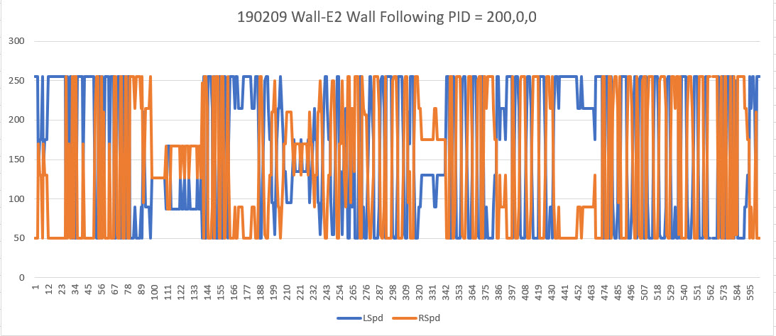
A long time ago in a galaxy far, far away, I set up a control algorithm for my autonomous wall-following robot Wall-E2.  After a lot of tuning, I wound up with basically a bang-bang system using a motor speed step function of about 50, where the full range of motor speeds is 0-255.  This works, but as you can see in the following chart & Excel diagram, it’s pretty clunky.  The algorithm is shown below, along with an Excel chart of motor speeds taken during a hallway run, and a video of the run.

for left wall tracking

for right wall tracking


Run 1, using homebrew algorithm

Note the row of LEDs on the rear. They display (very roughly) the turn direction and rate.

Since the time I set this up, I started using a PID algorithm for the code that homes the robot in on its charging station using a modulated IR beam, and it seems to work pretty well with a PID value of (Kp,Ki,Kd) = (200,0,0).  I’d like to use the knowledge gained for the IR homing subsystem to make Wall-E2 a bit more sophisticated and smooth during wall-following operations (which, after all, will be what Wall-E2 is doing most of the time).

In past work, I have not bothered to set a fixed distance from the wall being followed; I was just happy that Wall-E2 was following the wall at all, much less at a precise distance. Besides, I really didn’t know if having a preferred distance was a good idea.  However, with the experience gained so far, I now believe a 20-30 cm offset would probably work very well in our home.

So, my plan is to re-purpose the PID object used for IR homing whenever it isn’t actually in the IR homing mode, but with the PID values appropriate for wall-following rather than beam-riding.

PID Parameters:

For the beam-riding application I used a setpoint of zero, meaning the algorithm adjusts the control value (motor speed adjustment value) to drive the input value (offset from IR beam center) to zero.  This works very nicely as can be seen in the videos.  However, for the wall-following application I am going to use a setpoint of about 20-30cm, so that the algorithm will (hopefully) drive the motors to achieve this offset.  The Kp, Ki, & Kd values will be determined by experimentation.


13 February 2019 Update:

I got the PID controller working with a target offset of 25cm and Kp,Ki,Kd = 2,0,0 and ran some tests in my hallway.  In the first test I started with Wall-E2 approximately 25cm away from the wall. As can be seen in the following video, this worked quite well, and I thought “I’m a genius!”  Then I ran another test with Wall-E2 starting about 50cm away from the wall, and as can be seen in the second video, Wall-E2 promptly dived nose-first right into the wall, and I thought “I’m an idiot!”


The problem, of course, is the PID algorithm correctly turns Wall-E2 toward the wall to reduce the offset to the target value, but in doing so it changes the orientation of the ping sensor with respect to the wall, and the measured distance goes up instead of down.  The PID response is to turn Wall-E2 more, making the problem even worse, ending with Wall-E3 colliding nose-first with the wall it’s supposed to be following – oops!

So, it appears that I’ll need some sort of two stage approach the the constant-offset wall following problem, with an ‘approach’ stage and a ‘capture’ stage.  If the measured distance is outside a predefined capture window (say +/- 2cm or so), then either the PID algorithm needs to be disabled entirely in favor of a constant-angle approach, or the PID parameters need to change to something more like Kp,Ki,Kd = 0,1,1 or something.  More experimentation required.

Stay tuned,

Frank


WallE2 Robot in Arduino #include file hell

Posted 02 February 2019

After a vacation from my WallE2 autonomous wall-following robot code to recover from rotator cuff surgery (and creating/testing my new digital tensionometer), a week or so ago I decided it was time to get back into WallE2 mode.   At the time I thought this would be a piece of cake, as I had left WallE2 in pretty good shape, code-wise back in September 2018  (at least that’s what I thought!).

Instead, For the past couple of weeks I have been enduring what can only be described as “#include file hell”.   The first time I tried to compile my main program, I saw a couple of warnings in an i2cDev related library.   The code still compiled, but I take all warnings very seriously, and these weren’t there the last time I compiled the code.

So, I started trying to figure out what, if anything, had changed, and how to go about fixing whatever problem had caused the warnings to pop up.   Unfortunately, everything I did made things worse – and worse – and worse.   Nothing made sense.   Jeff Rowberg, the creator of the fine i2cDev collection of i2c device drivers was mystified, as was Tim Leek, the main guy on the Visual Micro forum.   Arggghhhh!

So, Jeff Rowberg suggested I try compiling the project in the Arduino IDE rather than in VS2017/Visual Micro, to eliminate any issues caused by that environment.   Up until this point I had actually  never used the Arduino IDE, much preferring the more helpful and feature rich VS2017/Visual Micro IDE. But, what the heck – how hard could it be?

Well, the answer was –  DAMNED HARD!   Using the Arduino IDE after the VS/VM environment was like moving backwards in time from the 21st century to the stone age –   having to rub sticks together to make a compile happen!   Moreover, the Arduino IDE created even more (and different) problems than I had experienced so far, meaning that I not only wasn’t draining the swamp, but the alligators were getting even more numerous!   Some of the ‘features’ of the Arduino IDE:

  • When the IDE is first launched, it comes up with the last .INO file loaded.   If you want a different file, it launches a new IDE instance with file->open; soon your desktop is littered with IDE instances.
  • When it tries to find a library based on a ‘#include <libraryName.h>’ line, it can’t handle [library name]-master as is common with libraries downloaded from GitHub
  • It requires exact name matching, including capitalization.   So ‘#include <libraryName>’ will not match with the ‘Arduino\Libraries\Libraryname’ folder.
  • Editing is clunky, and there’s no such thing as Intellisense.

After running around in circles with my hair on fire for the last week or so, making my wife miserable with my griping and inundating Tim Leek and Jeff Rowberg with ever-more-desperate cries for help, I finally decided that I was simply going to have to start over from scratch with my robot program (some 3000+ lines of code in the main program and over a dozen custom libraries), and just build it up piece by piece until everything works again – groan.   It’s not like I don’t have backups and wasn’t using revision control – I do and I was; it’s just that the programs that compiled cleanly back in September are generating warnings and errors now, and everything I do makes the problem worse!

Since the original problem seemed to be related to the library that runs the DFRobots MPU6050 module, I decided to start there.   After struggling up the learning curve on the Arduino IDE, I also decided I would make sure that each program step would compile cleanly in  both the VS/VM and Arduino IDE’s before proceeding to the next step.   I reasoned that since the Arduino IDE is much pickier about library locations and names, I could use it as sort of an editorial check on VS/VM; if it works in the Arduino IDE, the VS/VM setup will have  no problem.

For the DFRobots MPU6050 6DOF IMU module, I started with Jeff Rowberg’s ‘MPU6050_DMP6.INO’ example program buried way down in the ‘i2cdevlib-master\Arduino\MPU6050\examples\MPU6050_DMP6’.   According to the i2cDev ReadMe, I could either put the entire i2cDev-master folder in Arduino\Libraries and let the linker figure it out, or just put the required files in the project (solution folder for VS/VM, ‘sketchbook folder’ for Arduino IDE) folder.   I elected for the latter (local files) option, as I was at least a little suspicious that part or all of my original problem was caused by the compiler/linker loading from the wrong library folder in the i2dDev folder tree.   In addition, I completely removed the i2cDev folder tree from my PC and re-downloaded it from GitHub, placing it in a completely unrelated folder so that neither environment could possibly find it.   Then I copied the required header/.cpp files from the hidden i2cDev folder tree into the project folder.   In VS/VM I created a project called ‘MPU6050_DMP6_Example’ and copied the Arduino versions of I2Cdev.cpp/.h, MPU6050.cpp/.h, MPU6050_6Axis_Motion.h, and helper_3dmath.h into it. Then I started working to get this project to compile both in the VS/VM & Arduino IDE’s.

I’ve now gotten it to compile and link in the Arduino IDE (albeit with the same warnings I started with just before I went down the rabbit hole into header file hell).   However, I can’t get it to compile in VS/VM – it blows a whole bunch of errors of the form – apparently one error for each MP6050 function)

These errors proved impossible to correct, and nobody on either the Arduino or Visual Micro forums seemed to be able to help.   Finally in desperation I uninstalled and re-installed the Visual Micro extension to VS2017, and  that didn’t solve the problem either – exactly the same behavior.

So, last night I uninstalled VS2017 entirely from my system, and deleted the entire contents of the temp folder being used for temporary compile files.   On my system this was  C:\Users\Frank\AppData\Local\Temp.

03 February 2019

This morning I reinstalled VS2017CE and, using the Tools & Extensions menu, reinstalled Visual Micro. I left everything pretty much at the default settings (including the IDE selection and IDE location entries).   The only thing non-standard with the setup was the inclusion of ‘https://raw.githubusercontent.com/sparkfun/Arduino_Boards/master/IDE_Board_Manager/package_sparkfun_index.json’ in the ‘Optional additional boards manager urls’ field.   This was apparently left over from my previous installation.   I’m not worried about this particular setting, but it does indicate that not everything about the previous incarnation of Visual Micro was actually removed from my system.

After installing VS/VM, I ran through a few of my simpler projects, and so far they have all compiled w/o problems (or had understandable and easily fixable problems).   I also compiled each program in the Arduino IDE,  taking care to follow the Arduino IDE restrictions (no “-master” in library folder names, exact capitalization, etc).

  • BlinkTest.ino – very simple, no #includes
  • ClassTest.ino – Very simple class construction project – no #includes
  • DigitalScale.ino – Several #includes, including the HX-711 load cell library
  • StepperSpeedCtrl – uses   #include <Stepper.h>
  • AdaFruit_BTLE_UART_Test.ino – uses 7 different library #includes
  • Arduino_IMU6050_Test4.ino – uses i2cDev and MPU6050 libraries, along with SBWire, elapsedMillis, and PrintEx.   this compiled OK, but with the same warnings (overrun & ‘one definition rule’) as when I first started this odyssey.   Fortunately, that’s all that happened – I didn’t get the ‘(.text.startup+0x1e4): undefined reference to MPU6050::initialize()’ error – yay!   This program also compiles in the Arduino IDE, with the same exact warnings.   So, it appears I may be back where I started on this odyssey, with a program using the MPU6050 libraries that compiles OK but with one   understandable/fixable warning (the overrun warning) and one mystery warning (the ‘one definition rule’ warning)
  • MPU6050_DMP6_Example:   spoke too soon!   This program blows the same  ‘(.text.startup+0x1e4): undefined reference to MPU6050::initialize()’ errors as before in VM, but compiles fine (albeit with the same two warnings as always)   in the Arduino IDE.
  • Arduino_IMU6050_Test4:   This is a program I created some time ago, and I found that it compiles/links fine (stil with the overrun/ODR warnings), both VS/VM and Arduino IDE

In desperation, I decide to create a completely new Arduino project in VS/VM, copy the ‘known-good’ code from  Arduino_IMU6050_Test4 into it, and then start hacking it down to the point where it fails.   Surprise surprise, when I did this, the new project (UnDefTest2) failed right away in VS/VM, blowing LOTS of linker errors!   Moreover, it compiled/linked fine in Arduino IDE – how could this be?   There MUST be something different about the VS/VM environment between  Arduino_IMU6050_Test4 and UnDefTest4 – but what?   After putting the two projects up side-by-side (this is where a dual monitor setup comes in REAL handy), I finally twigged to the difference; in the ‘working’ version, the local header/cpp files had been ‘added’ to the project’s ‘Header Files’ and ‘Source Files’ folders via the Solution Explorer (right-click on the folder icon, select ‘Add Existing…’, select the desired files, click OK). As soon as I added the relevant files to the UnDefTest4 project, it compiled/linked fine – YAY!!

I could not believe what I was seeing!   For some reason, VS/VM refused to process header/cpp files in the same folder as the .INO file, even though I had carefully checked the ‘Local Files Override Library Files’ option in the ‘Vmicro->Compiler’ menu.   At the same time, the Arduino IDE  always searches the local folder before anything else, so simply placing the relevant files in the local folder does the trick.   The fact that Visual Micro requires an additional (and non-intuitive) step for this boggles the mind.

04 February 2019

OK, when I started all this foolishness I was trying to find out (and fix) whatever was causing the ‘One Definition Rule’ (ODR) violation warning I was getting on all my programs that used the MPU6050.   I really  really hate warnings, and I was determined to get to the bottom of this, and I finally did!

The ‘one definition rule’ (ODR) warning is caused when the compiler/linker sees code that can produce two different definitions for the same object. If that can happen, EVER, then an ODR violation warning is issued. Believe it or not, that is exactly what happens when the compiler processes MPU6050.H – it sees that there are some conditions for which two different descriptions of the MPU6050 class could exist – and says “no no”. The relevant portion of the class definition is shown below:

When the compiler sees these lines, it says to itself; “Hmm, the way this is written, it is theoretically possible for there to exist  two different versions  of ‘Class MPU6050’, one with just two private member variables (devAddr & buffer) and one with four (with the addition of dmpPacketBuffer & dmpPacketSize), and this is a strict no-no; I’m going to whack that programmer across the head with an ODR violation!”

If the #ifdefined and #endif lines are commented out – the ODR warning goes away

Now, I suspect nobody has ever had a problem with this issue, as it would be very unlikely to have a project where BOTH versions of MPU6050 are in play, but of course the compiler doesn’t see it this way.

On a slightly different, but related subject, the OTHER warning was due to a potential integer overrun in the dmpGetGravity() function, as shown below:

if the last line of the above calculation is changed to (note the addition of ‘UL’)
– (int32_t)qI[2] * qI[2] + (int32_t)qI[3] * qI[3]) / (2 * 16384UL);
then this warning goes away as well.

Mission accomplished!   I now have MPU6050 code that compiles without errors (or warnings!!) in both the VS/VM and Arduino IDE environments.   Along the way I learned more than I ever wanted to know about ‘One Definition Rule’ violations and the innards of both the VS/VM environment and the Arduino IDE.

to paraphrase a quote attributed to Abraham of Lincoln:

I feel like the man who was tarred and feathered and ridden out of town on a rail. To the man who asked him how he liked it, he said: “If it wasn’t for the honor of the thing, I’d rather walk.”


Stay tuned,


Frank


Digital Tension Scale, Part V

posted 09 January 2019,

In my previous post on this subject I described the components I planned to use for my Digital Tension Scale project, and also the design for a box that would mount directly on the S-shaped load cell assembly.

This post describes the ‘final’ (to the extent than anything I do can be considered final) assembly of the completed system into my 3D-printed housing, and the results of some initial battery-powered testing.

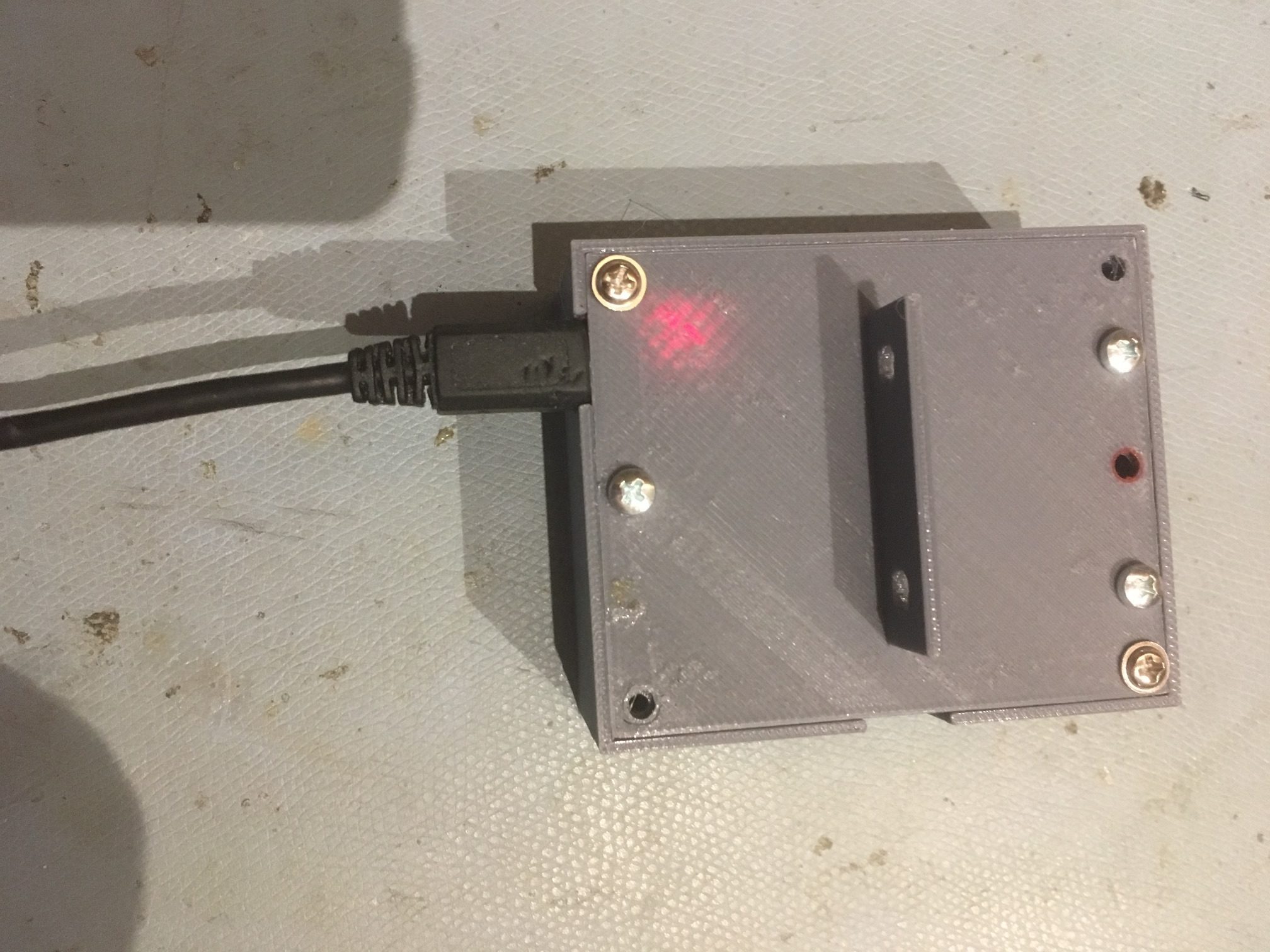
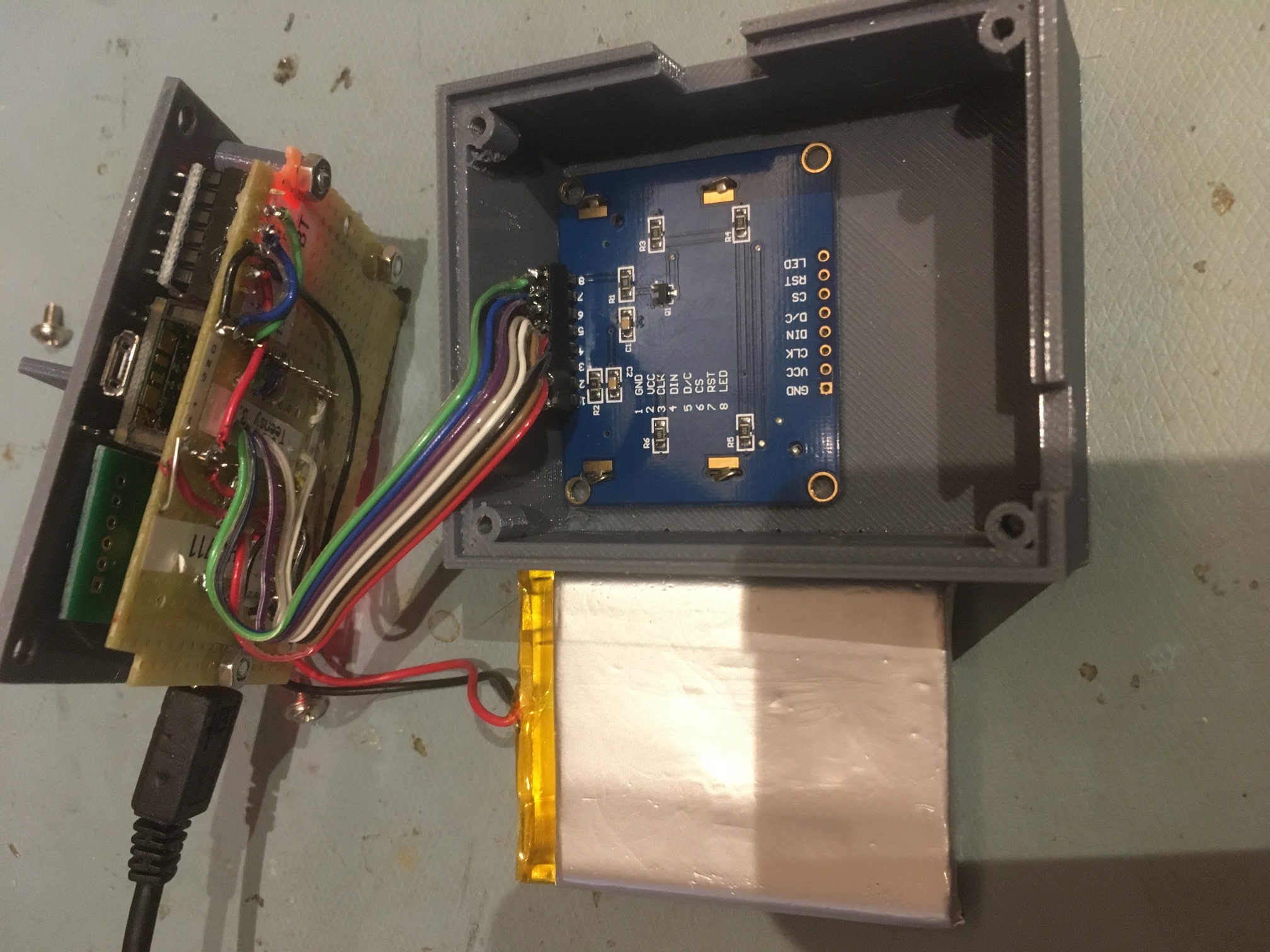
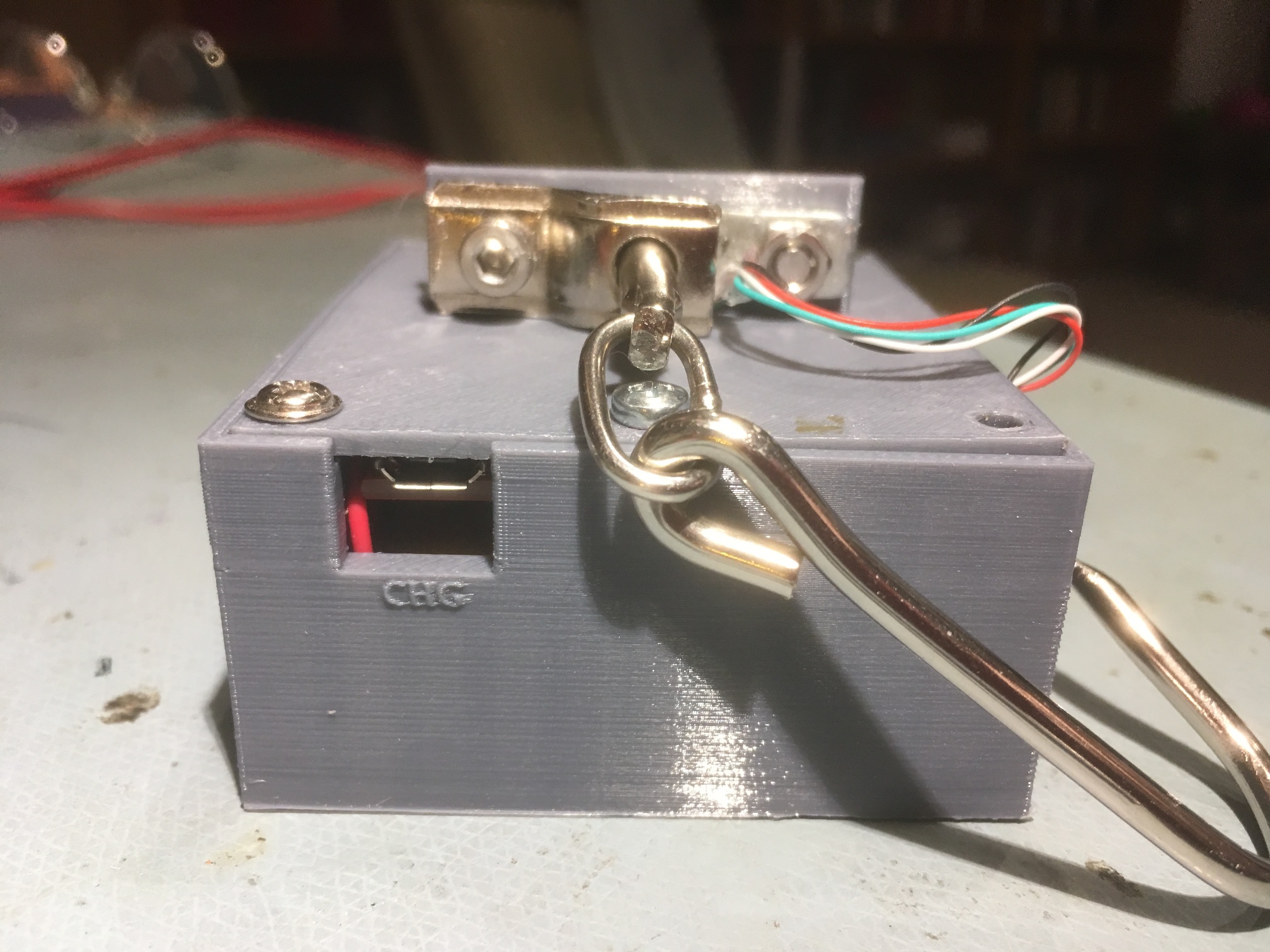
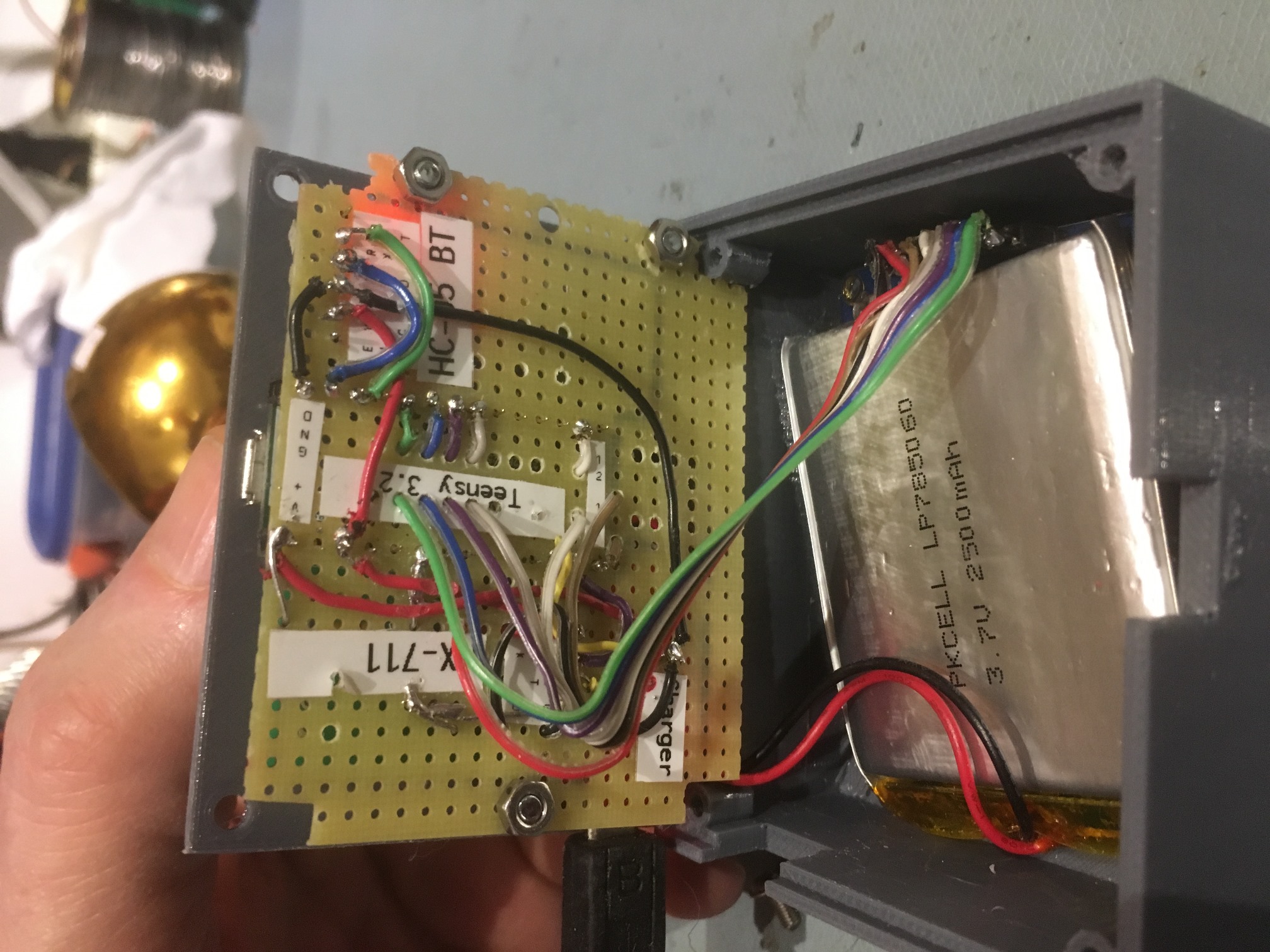
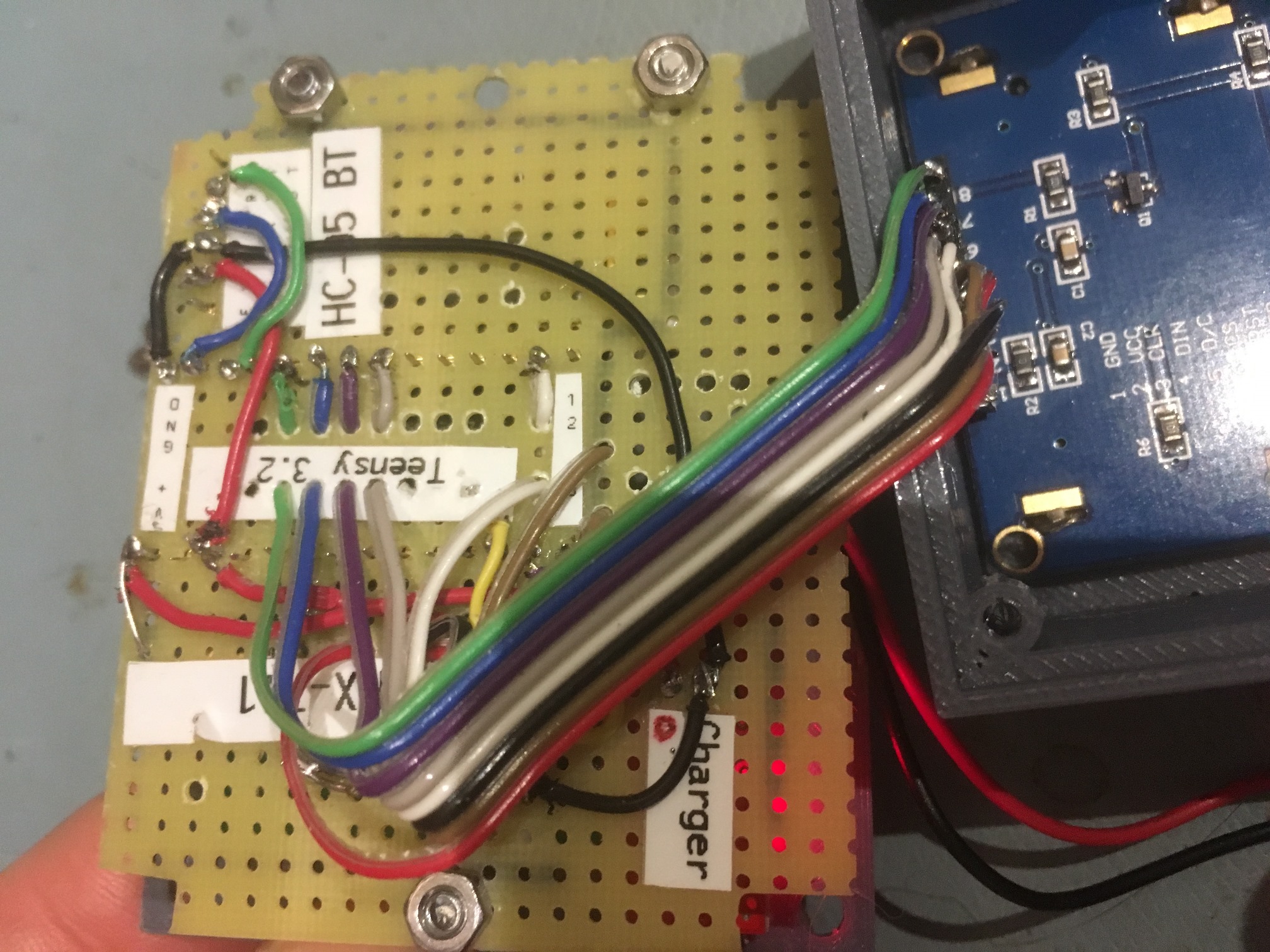
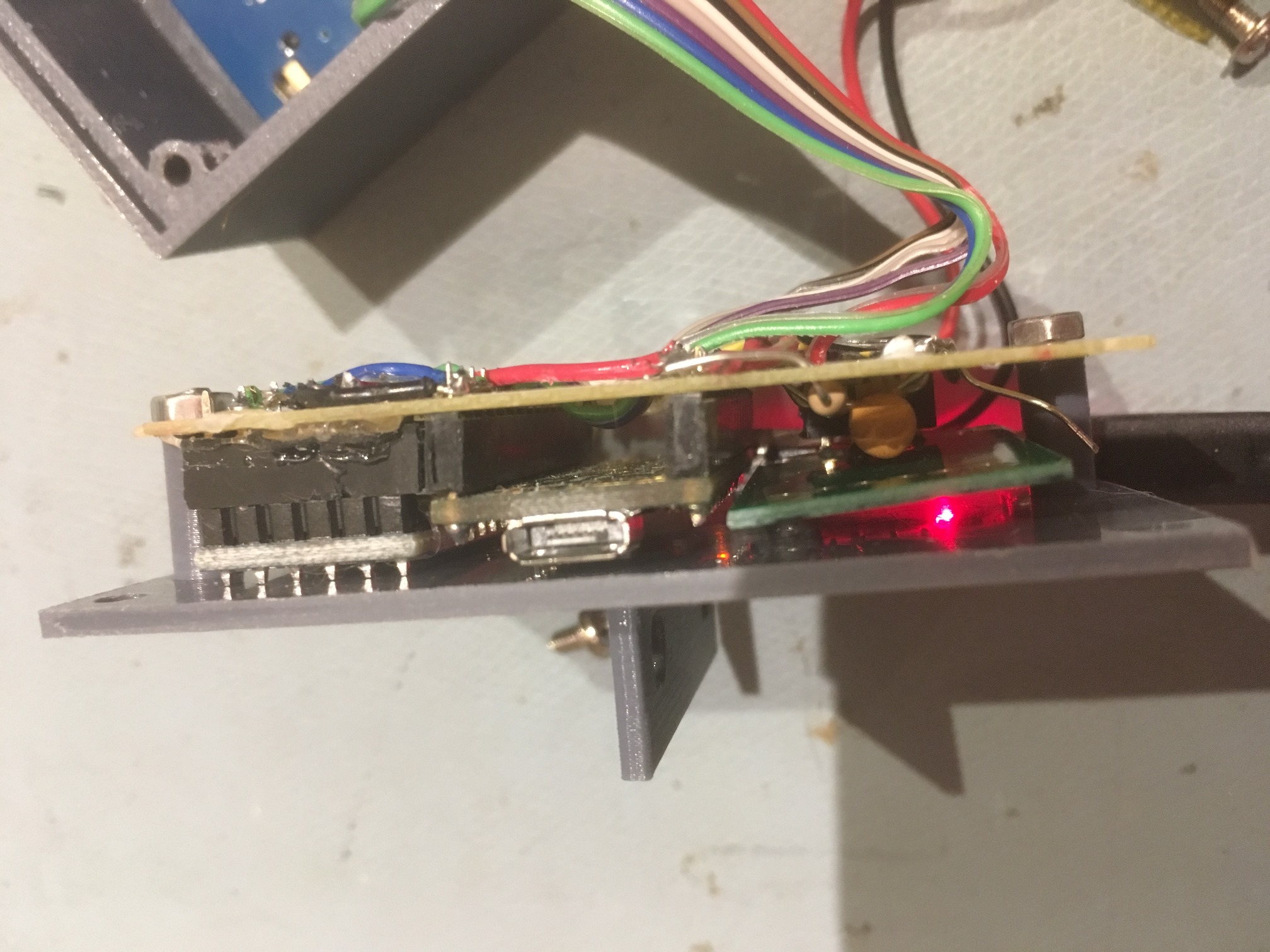
As shown in the following photos, the major components (Teensy 3.2 microcontroller, HC-05 Bluetooth Module, HX-711 load cell amp/A-D, and Sparkfun ‘Basic’ LiPo Charger) were mounted on perfboard, which was then in turn attached to the box lid via a set of custom-printed standoffs.   A short piece of ribbon cable connects the Teensy to the LCD display.   The general idea behind this physical layout is to allow easy access to the electronics for troubleshooting, and to allow for battery charging and/or Teensy programming without having to open the box.

3D-printed housing. Note the glow from the Sparkfun charger LED

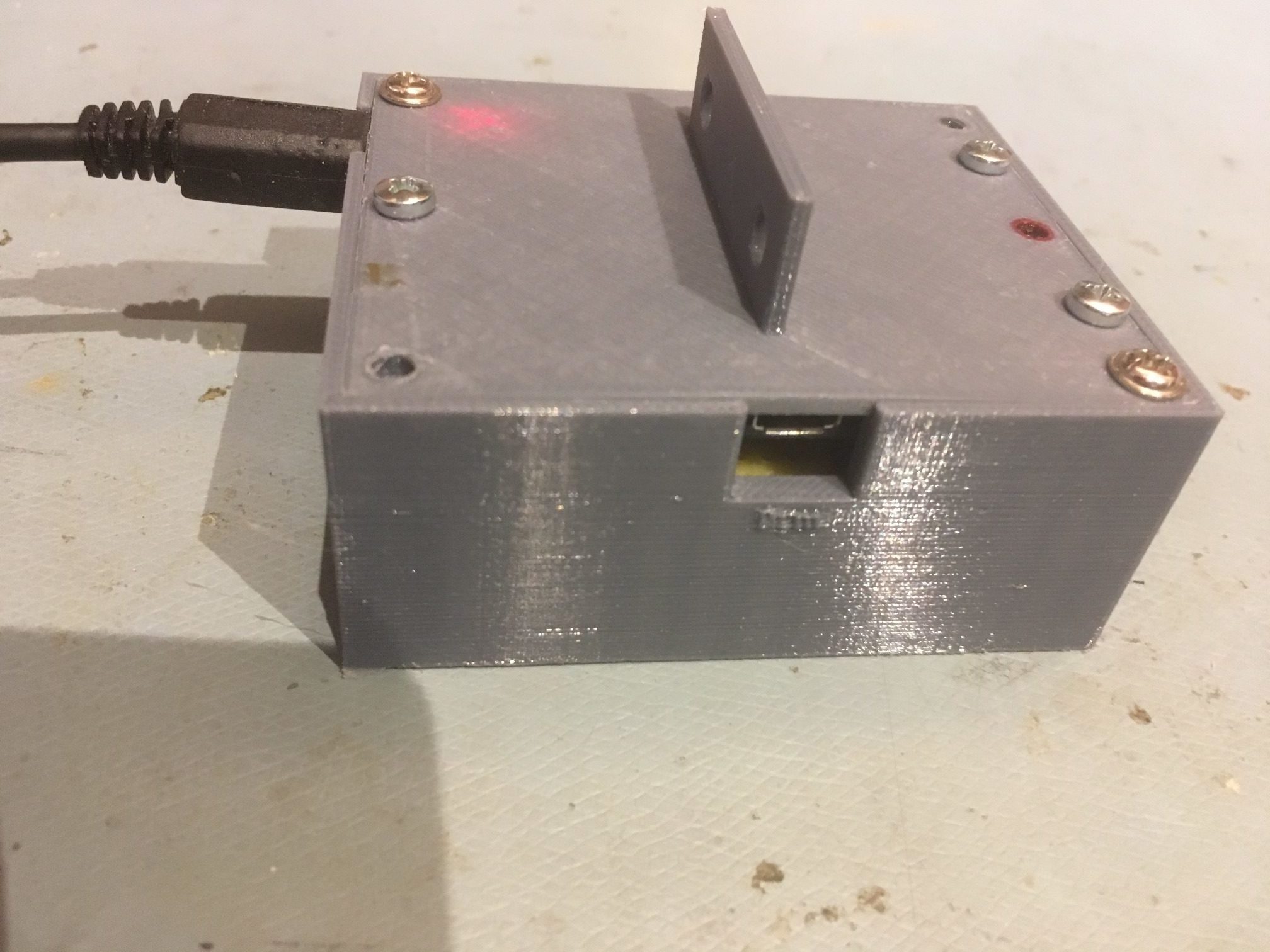
View of housing showing the access port for supplying USB power and/or programming the Teensy

View with the lid and electronics board removed. The LCD display is face down in its cutout

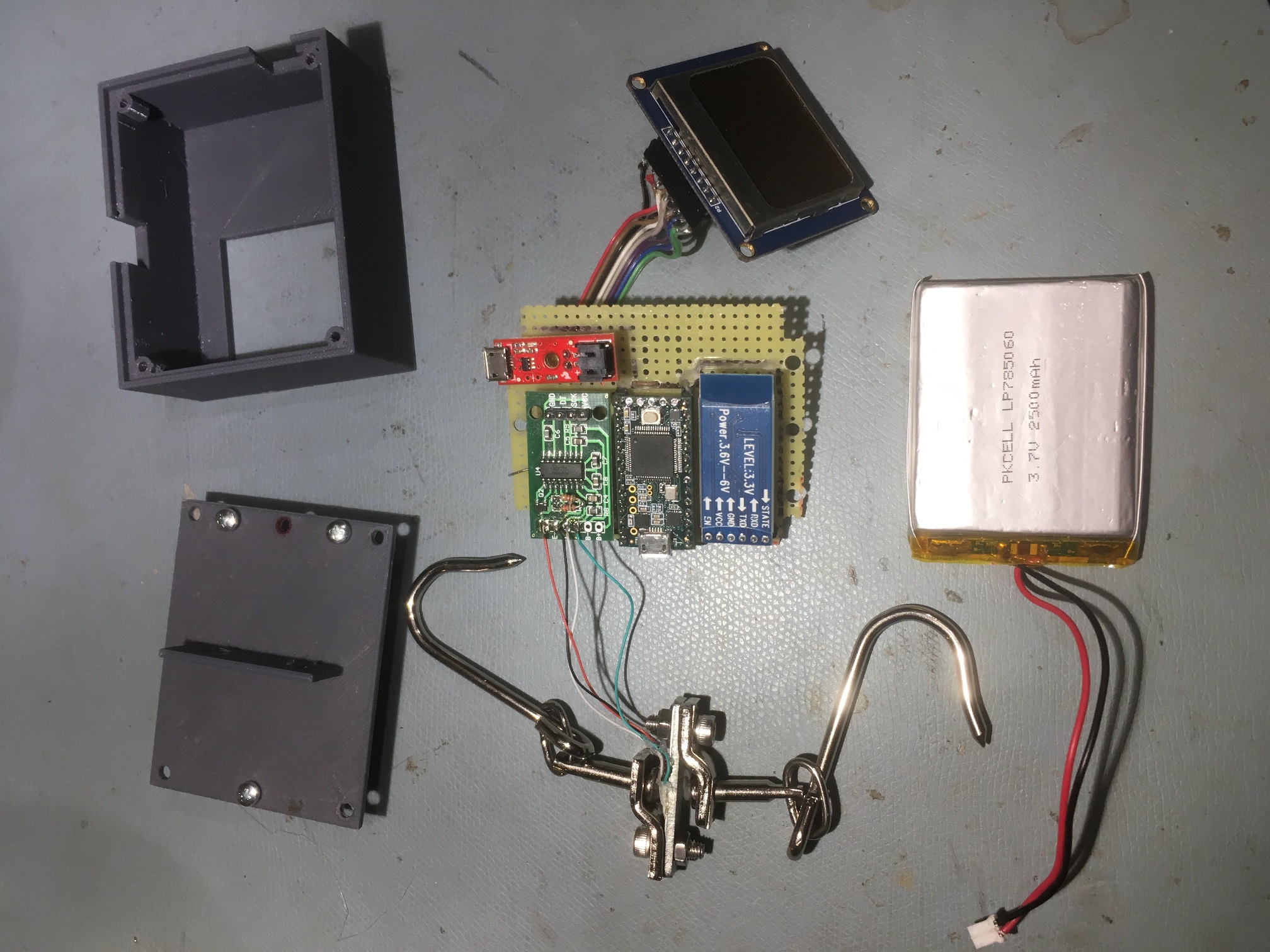
Exploded view showing all system components

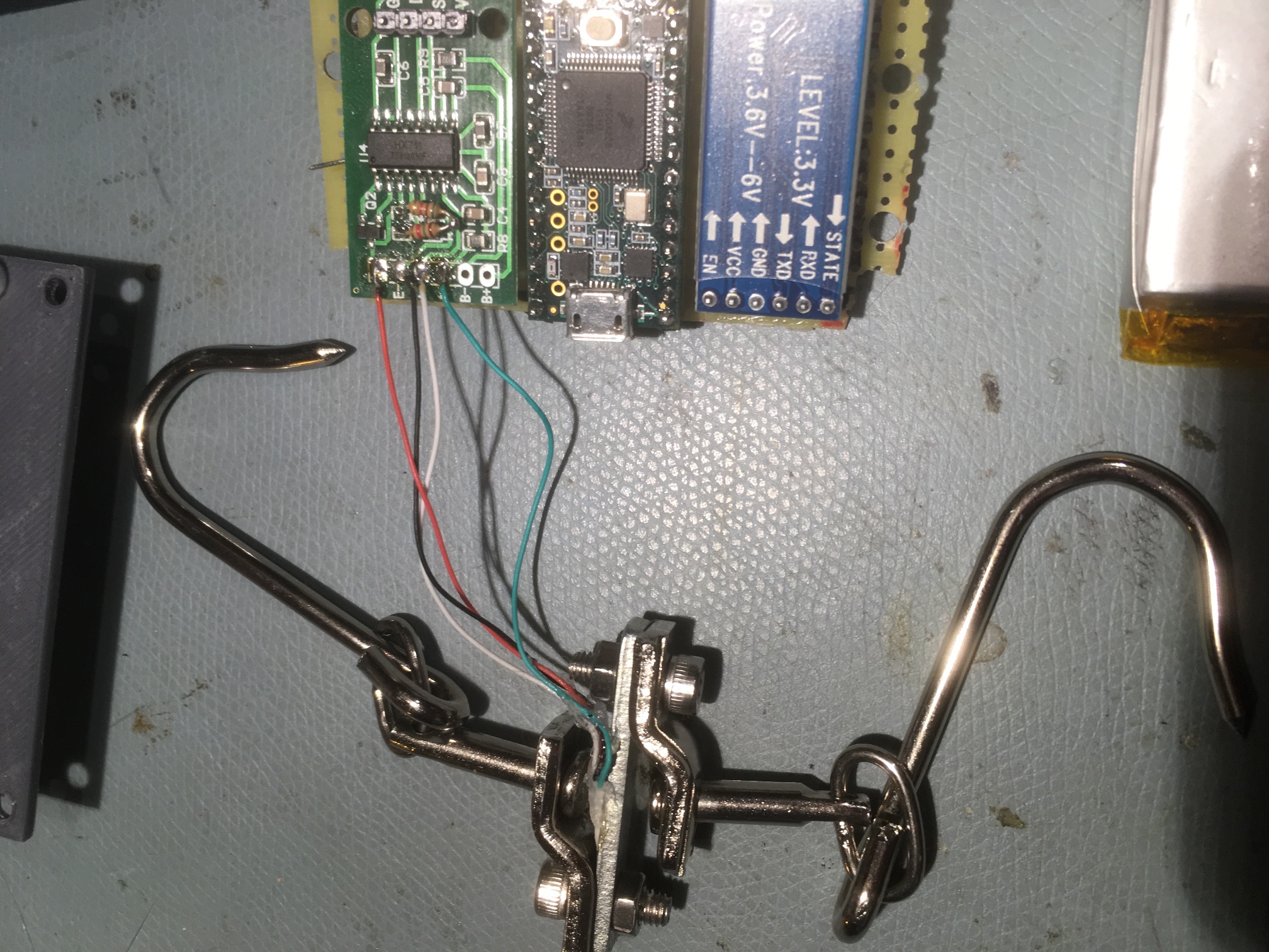
Showing connections from load cell to HX-711

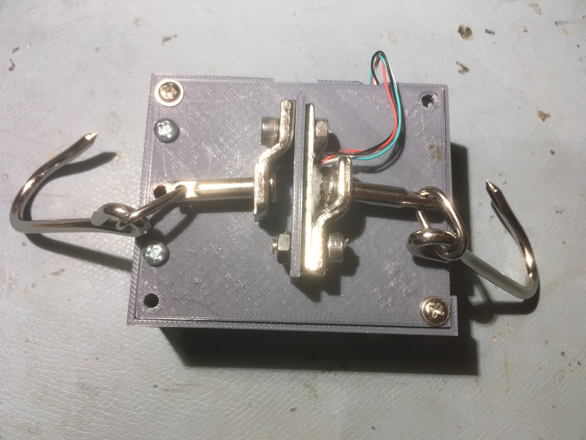
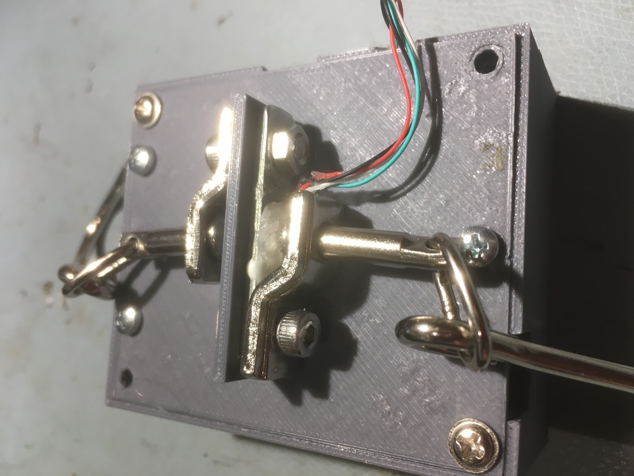
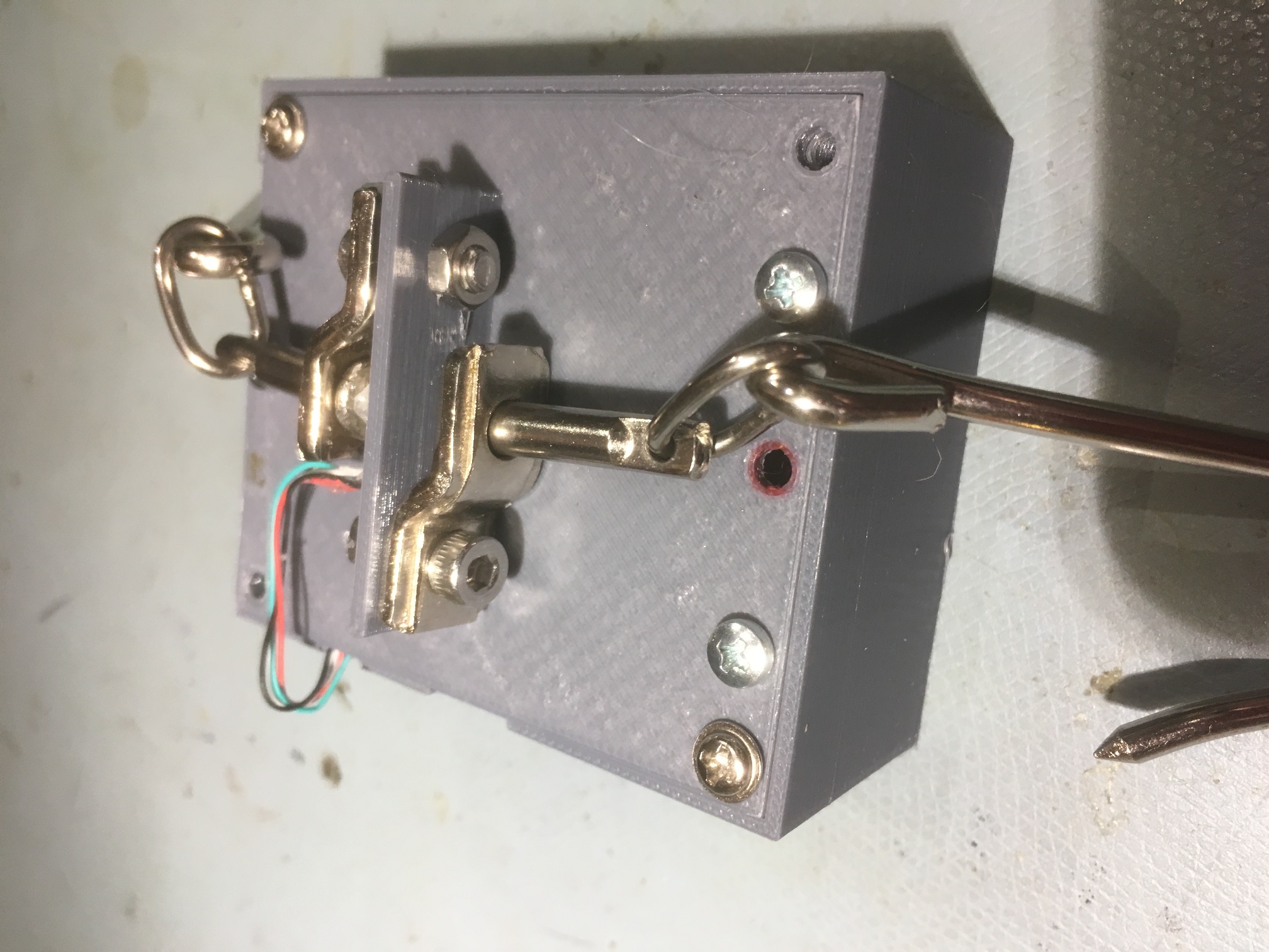
Top view showing how load cell attaches to the housing

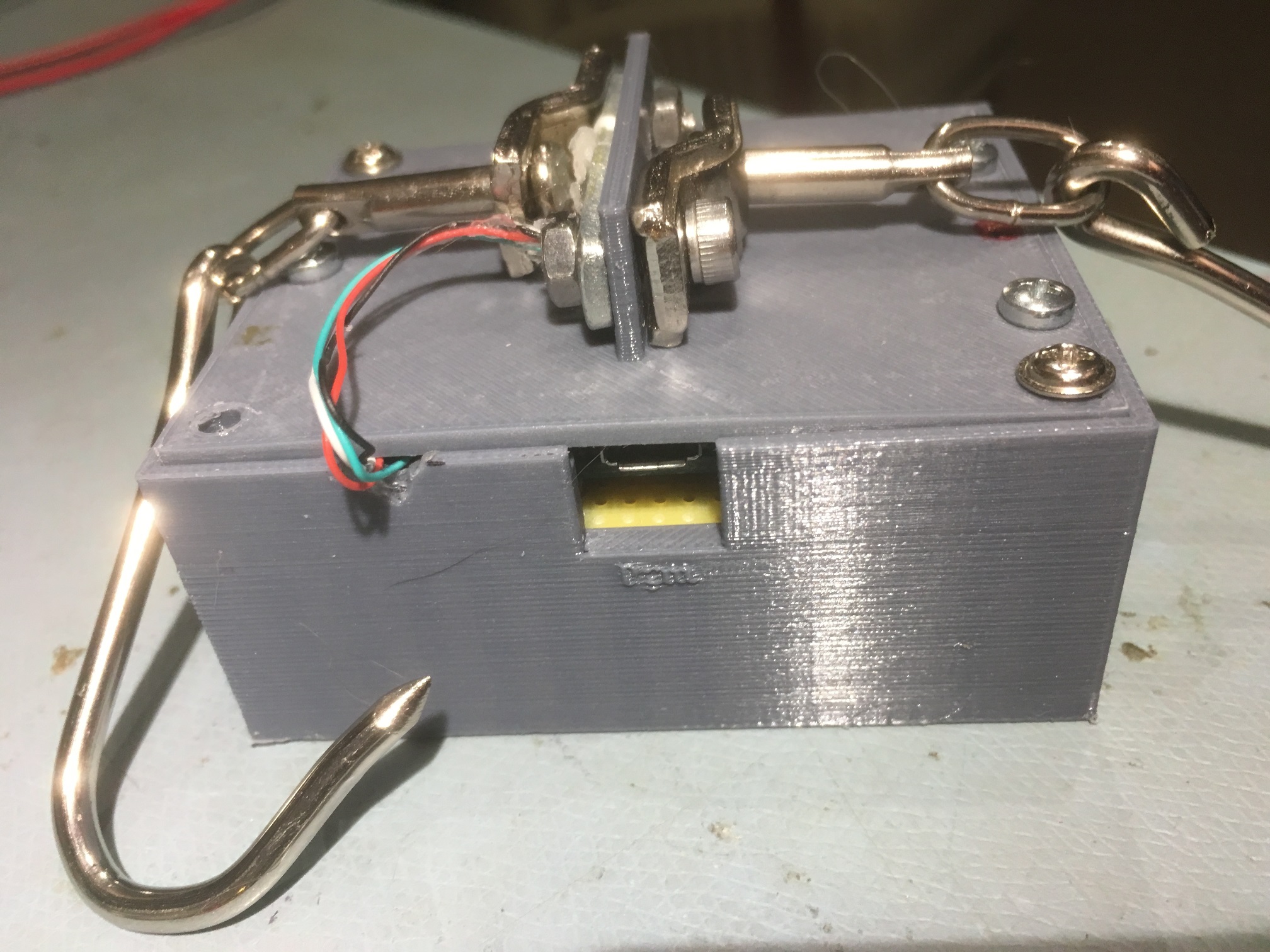
Closeup showing load cell lead routing and power/programming port

End view showing charging port


Preliminary Testing Results:

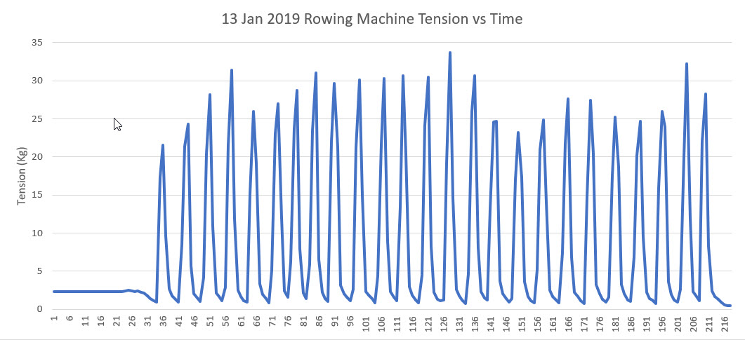
At this point I have everything running on battery power only inside the box, and I have been able to demonstrate remote data capture on my PC using the HC-05 BT link.   The following image shows the data taken from my rowing machine, and a short video demonstrating the setup.

Complete Code:

Here is the complete Teensy 3.2 program as it stands today.   As you can see if you inspect the code, I have the Teensy low-power stuff turned OFF for the moment (that’s the purpose of the ‘#define NO_SNOOZE’ statement.


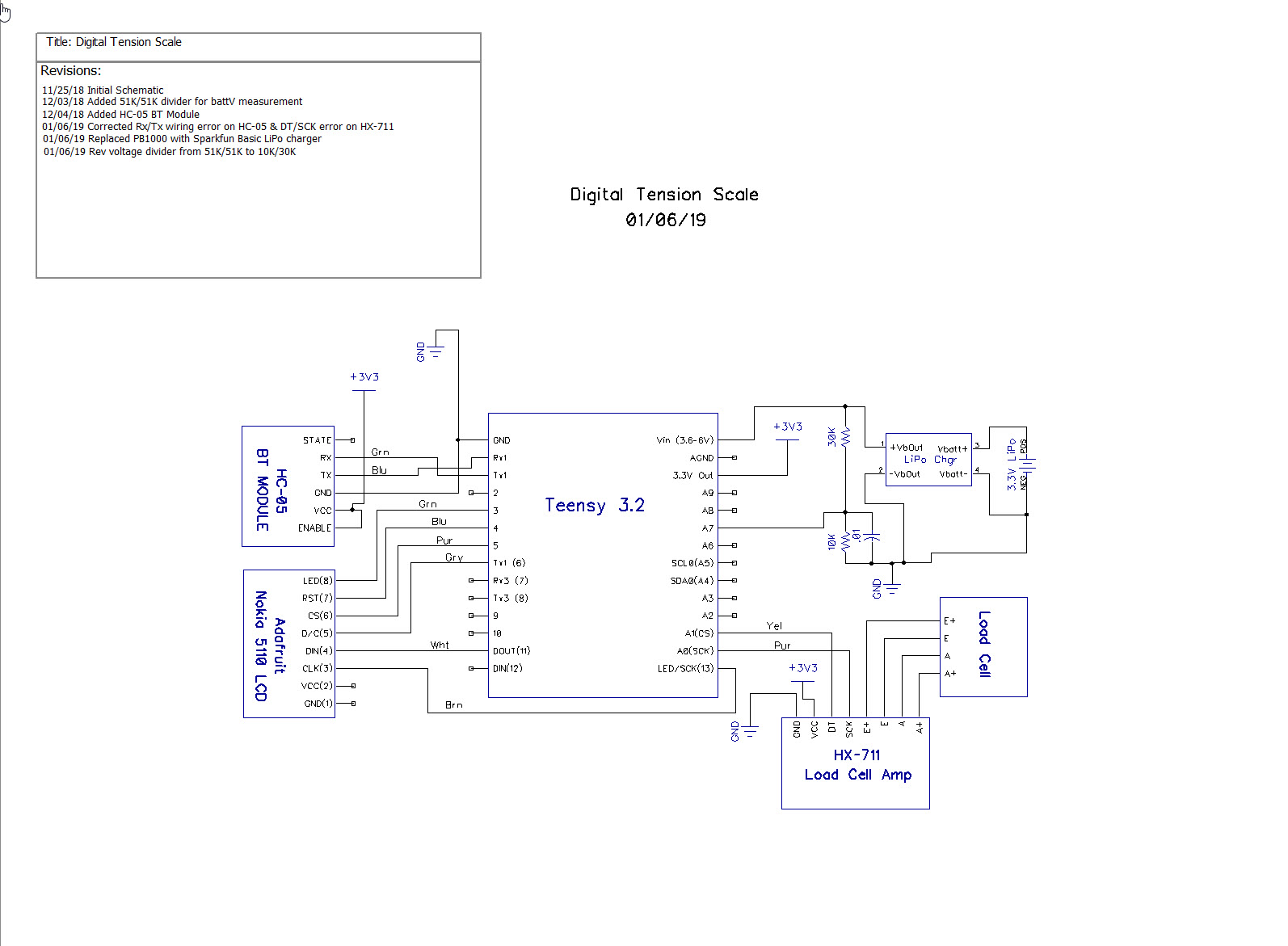
Schematic:

Future Work:

  • Do some more work to reduce power consumption to extend the battery life.   I got the ‘Snooze’ feature to work on the Teensy, but that only reduces the Teensy’s power consumption; it does nothing directly to reduce the power consumption of the other components.   I tried using a MOSFET to turn the HC-05 BT module on & off, and found this to be impractical, as then the module loses its connection to the remote data collection device.    I have also tried removing power from the LCD module, but that also turned out to be problematic.

Stay tuned,

Frank


Digital Tension Scale, Part IV

Posted 25 December 2018

In my copious free time I have been refining the design for a low power battery operated tensionometer.   In my last post on the subject, I had described the components I had planned to use, and in the ensuing weeks I have been working on implementing this design.   There are several challenges in this project:

Bluetooth Link:

There are a huge number of Bluetooth products out there in the Maker-verse, with varying degrees of Arduino support, and widely varying performance characteristics.   To add to the confusion, there is ‘regular’ Bluetooth and the more recent  ‘BLE’ (Bluetooth Low Energy) which are completely incompatible with each other.   As I now understand it, BLE is synonymous with Bluetooth 4.0+ (the iPhone 4S was the first smartphone to implement the new standard).   However, the most common product in use in the Arduino world seems to be the venerable HC-05 ‘regular’ Bluetooth module, available from your local grocery store (well, not quite, but from almost everywhere else!) for not much more than a few pennies

I had no previous experience with BT modules, so this part of the project took some time, and was the last major part to be accomplished.   After receiving my HC-05 modules from China, I used this tutorial to get started.   The real challenge for this part of the project wasn’t getting the HC-05 hooked up to the microcontroller – it was sorting through all the layers of BT-related settings on my Win 10 laptop to pair with the HC-05 device and determine which serial port did what.

  • In Windows 10, I used the ‘Bluetooth and other devices settings’ panel (Settings -> Devices -> Bluetooth and other devices) to find and pair to the HC-05.   The device shows up as ‘HC-05’ and the default pairing password is “1234”.
  • When the HC-05 is paired it automatically sets up at least two serial ports that show up in device manager as ‘Standard Serial over Bluetooth’ ports, as shown below.   However, only one of these ports is actually usable for two-way communication, and it isn’t clear to me why, or how to tell which is which;   I had to experiment with each available ‘SSoB’ port to figure out which to use  (so far, it seems like the highest-numbered port is the proper one).
  • After the HC-05 is paired and the com ports are set up, then any serial terminal app (I used RealTerm) can be used to communicate between the PC and the microcontroller via the HC-05.
  • On the microcontroller (I used a Teensy 3.2 with multiple hardware serial ports), I wired the HC-05 to Serial1 leaving Serial (Serial0) available for normal communication between the Teensy and my Visual Studio 2017 Community Edition/Visual Micro add-on for Arduino development platform.

Physical Layout:

The original idea behind this project was to create a self-contained battery-operated digital weight scale that could display weight values on a local display, but could also stream the data live to a remote recording station like a laptop or smartphone. The ‘self-contained’ part requires that all the electronics be mounted on the S-shaped load cell assembly itself, and to that end I designed a housing that connects to the two bolts that hold the arms of the load cell.   The idea is that all the electronics save the LCD display and the battery will be mounted to the underside of the box lid so that servicing would be easier.   Also, by mounting everything to the lid, I can make cutouts for the charger and Teensy USB connectors for easy charging and reprogramming.   After several iterations in TinkerCad, I came up with the following design

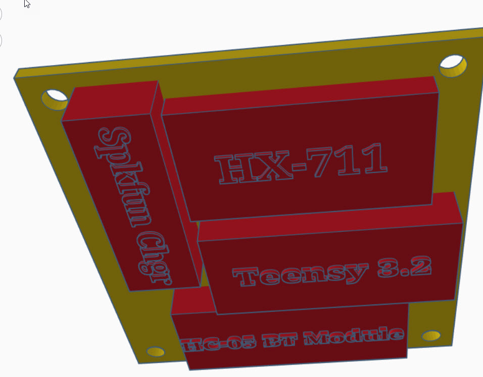
Looking up at the underside of the box lid, showing all modules except the battery and the LCD display

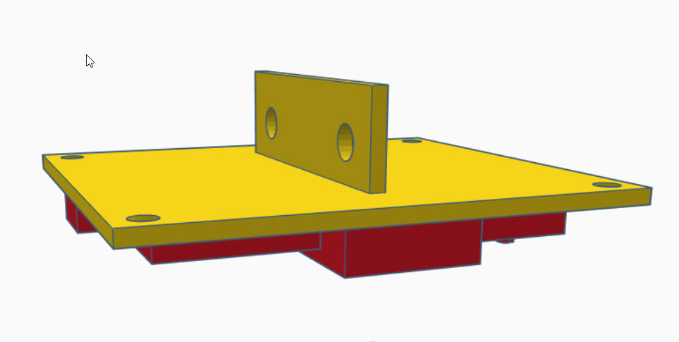
Showing the top of the lid with the mounting bracket for the load cell

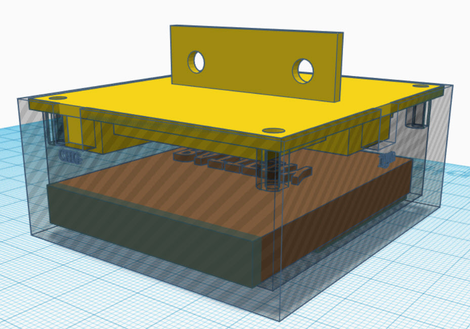
Isometric view with transparent box walls. The LCD display module is under the battery.   Note the cutouts for the charging and programming USB-C connections

Module Integration:

I had previously tested each module individually, but hadn’t had all of them working at the same time.   I had tested the HC-05 with an Arduino Mega, and I had tested the load cell with both a Sparkfun Pro Micro and with a Teensy 3.2, and I had tested the Nokia LCD display with a Teensy 3.2, but I hadn’t put everything together.   So I wired everything up on my half-size ASP plugboard and got it all working together with a simple program (included below) that exercised the LCD Display, the load cell, the BT module, and the battery charger, as shown in the following photos

RealTerm Serial Terminal Program showing load cell readouts collected wirelessly via the Bluetooth HC-05 modules

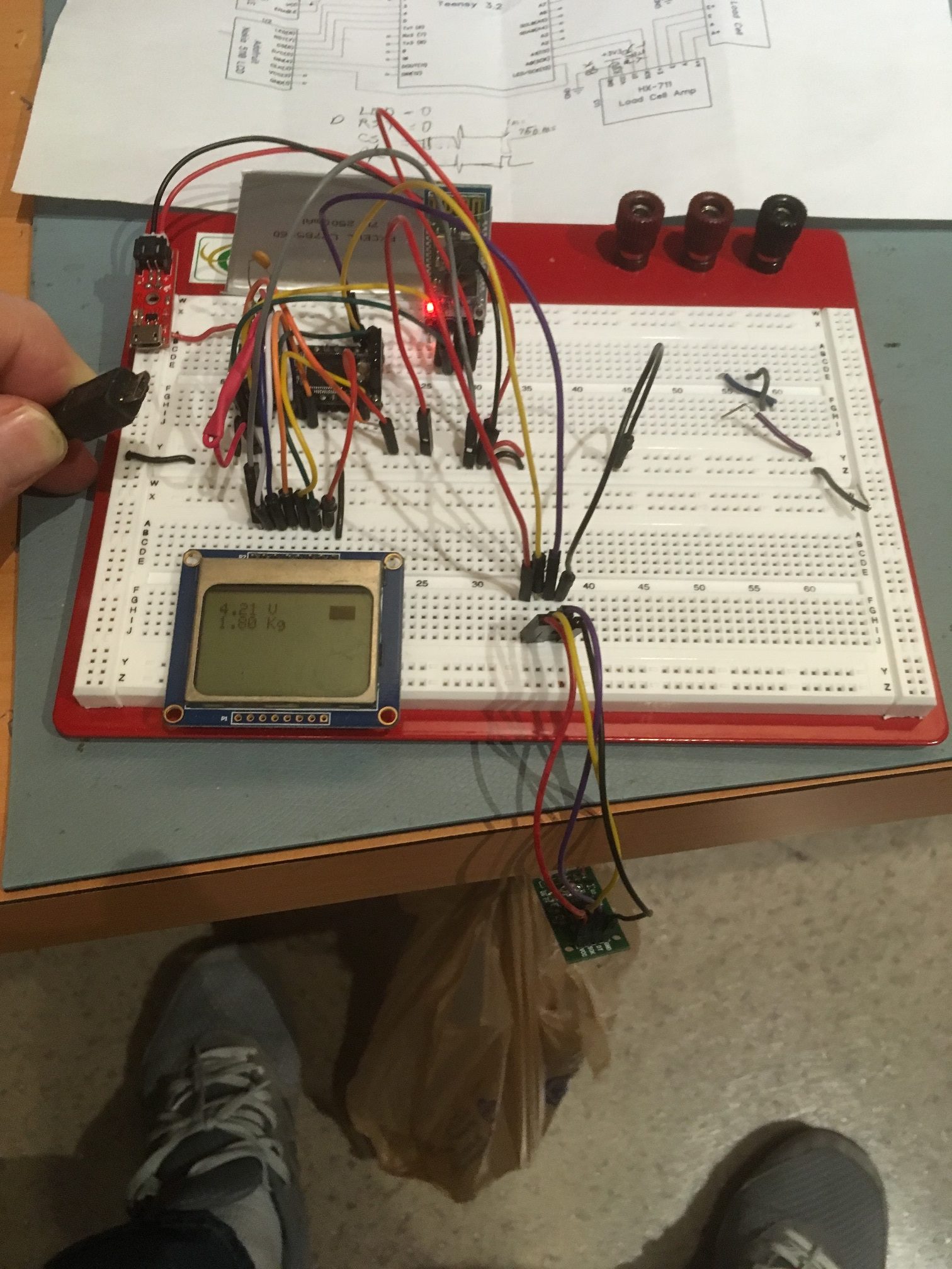
HC-05 Bluetooth, HX-711 Load Cell Amp, Sparkfun Charger, and Teensy Microcontroller modules integrated together. Note disconnected USB cable showing that the circuit is running on battery power. The scale is currently measuring 1.8 liters of water in the suspended plastic bag (note the ‘1.8 Kg’ reading on the LCD display)


Software:

The software used for the above integration tests is a reasonably complete sketch for day-to-day use of the digital weight scale.   It displays the measured weight on the LCD display, and also sends it to the USB serial port for display on a directly connected PC, and to the HC-05 Bluetooth module for display/capture via a BT-connected laptop or smartphone.   This program is shown below:

However, this program depends on the proper calibration of the load cell, which I have been doing with a separate sketch (also included below):

What I need to do now is to combine these two programs into a single sketch with ‘operating’ and ‘calibration’ modes.   My calibration program already does this to some degree, as it waits 5 seconds on startup for the operator to send the ‘y’ key via the direct-connect serial port. If the ‘y’ character is detected within this window, then the program starts the calibration sequence; otherwise it starts taking measurements as normal.   This behavior needs to be expanded somewhat in that it should accept a calibration command either through the direct-connect serial port (Serial) or via the BT port (Serial1).

Low Power Operation:

I have already done some experimentation on low-power operation of the Teensy 3.2, using Colin Duffy’s fine ‘Snooze’ library, and have determined that I can easily drop the Teensy’s operating current from around 20-30 mA to about 1-2 mA by putting it to sleep during periods of load cell inactivity.   Assuming I get the full 2500 mA hours out of the battery, then I can expect something like 1000 hours or about 40 days between recharges.   However, more work needs to be done to get the low power mode fully operational.


Stay Tuned!

Frank


Digital Tension Scale, Part III

Posted 25 November, 2018

Over the Thanksgiving weekend I had a chance to do some more work on my digital tension scale project.   My wife and I drove to St. Louis to visit our kids and grand-kids, and its a 6-hour drive each way.   I make sure we have an audio book going for my wife, and as a consequence I get 6 hours of (mostly) uninterrupted geek time to work on things like this project.

As I mentioned in Part II, my goal is to construct a battery-operated tensionometer that can be mounted directly on the dual-hook S-shaped tension block, as defined by the features delineated in Part II.   After doing some more web research, I came up with the following possible components for the system:

Display:

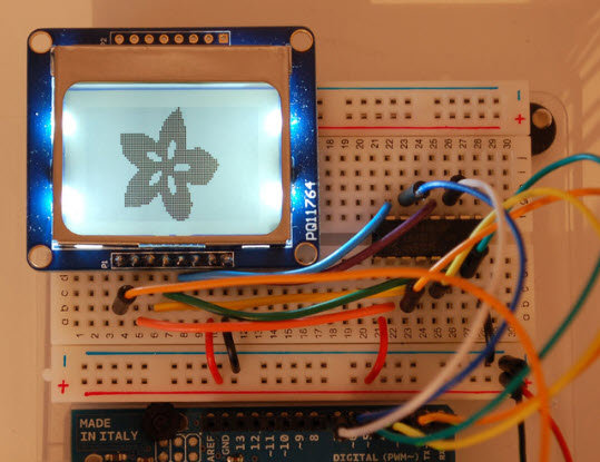
Apparently, the Nokia 5110 84×48 pixel monochrome LCD display used in prehistoric times as the display in Nokia cellphones has found a second career as a simple, low power display for battery-operated devices like the one I envision.


Nokia 5110 Monochrome LCD display

Battery & Battery Charger:

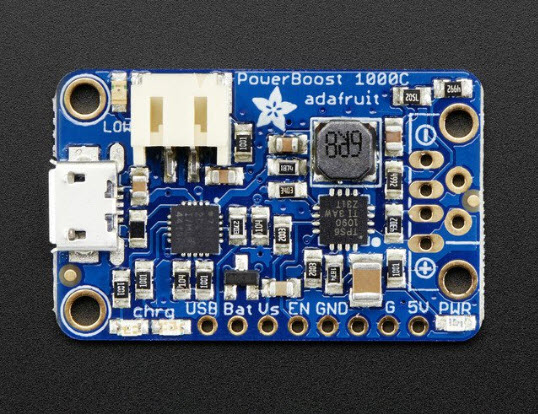
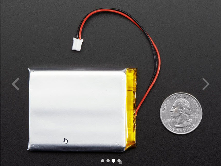
The LCD display will operate quite nicely from 3.3V, so as long as I can come up with a 3.3V micro-controller (like the Teensy 3.2) and a small, capable LiPo charger, I should be in business.   For this component, I plan to use the Adafruit PowerBoost 1000C and something like the 3.7V 2500 mAh battery as shown below

Adafruit PowerBoost 1000C single-cell LiPo charger

3.7V 2500 mAh LiPo battery


I don’t think I’ll need the 5V boosted output from the PB1000C and the entire thing may be a bit of overkill for this project, but I had them hanging around from a previous project, so…

MicroController:

For this I plan to use one of  Paul Stoffregen’s magical Teensy 3.2’s.   Again this is probably  way overkill for the project, but…

Wireless Connection:

This component is the one for which I have the least understanding and confidence.   I currently use a Pololu Wixel for wireless serial comms and programming with my autonomous robot, but I haven’t figured out how to use it with a Teensy, and I thought maybe there were better solutions out there by now anyway.   So, after some more web searching I found that many ‘makers’ are using the HC-05/6 Bluetooth modules for this purpose.   Hopefully with this module I’ll be able to use a Bluetooth connection from the tensionometer to my laptop or even my cellphone to perform calibrations and collect real-time tension data.

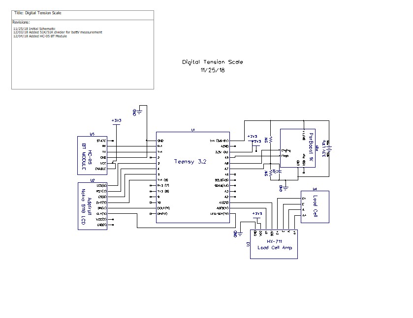
Combining all these with the HX-711 load cell amplifier, I came up with the following system schematic.


Stay tuned!

Frank


Digital Tension Scale, Part II

Posted 17 November 2018

In a previous post on this subject, I described a digital tension scale arrangement using a load cell incorporated into a 2-hook tension measurement setup, interfaced to a common HX711 ADC board, and a Sparkfun Pro Micro ATMega32U4 microcontroller.

After (finally) getting the setup to work and getting some initial real-time tension measurements on our rowing machine, I decided to see if I could improve the usability of the overall system, with the goal of constructing a fully automatic battery powered tension scale, with the ability to communicate wirelessly to my PC for data acquisition and programming.

Desired Features:

  • Easy calibration:   The system should offer a calibration option when connected to a PC/Smartphone, but otherwise should use the last calibration data (stored in EEPROM) for measurements.
  • Battery operated: This implies a low-power mode to extend battery life if using primary batteries, and/or a charging arrangement if using secondary (rechargeable) cells.
  • Local display:   A low power display (LCD?) for local tension measurement display
  • Wireless capability:   A wireless connection to a PC or smartphone for real-time data acquisition.
  • Small size:   I would like to mount the entire system on the 2-hook tension measurement assembly itself.

Easy Calibration:

The calibration procedure associated with my previous post was a PITA, to say the least, so I decided to attack this problem first.   I modified the software to allow the user to skip calibration entirely or to calibrate the tensionometer automatically using any known weight.   The new software is shown below:

When run on my PC, this produced the following output

Here are a couple of photos showing the calibration process with my current setup

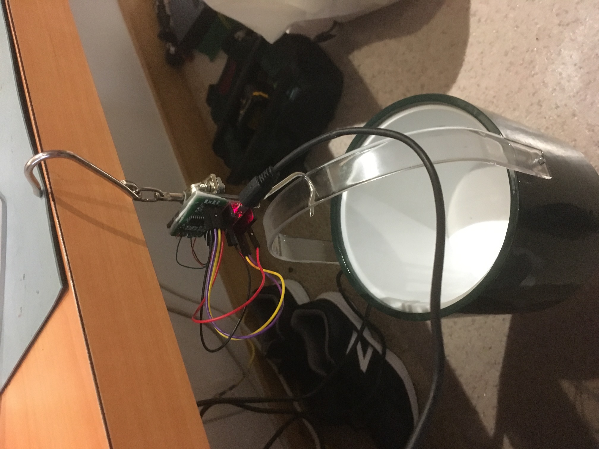
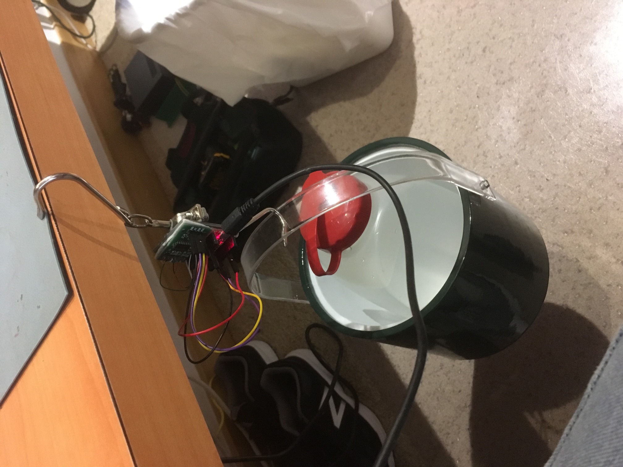
‘Tare Weight’ configuration, used to zero out the contribution from the bucket

Calibration configuration. Bucket now contains 1.8L water (1.8 Kg)

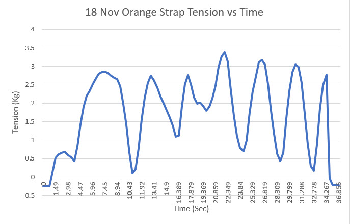
After calibrating, I tested the the system by measuring tension vs time with an elastic strap I am using as part of my rotator cuff surgery rehab, as shown in the following short video clip

The data from this experiment was captured on my PC and plotted in Excel, as shown below

Tension vs time for the orange elastic strap shown in the video

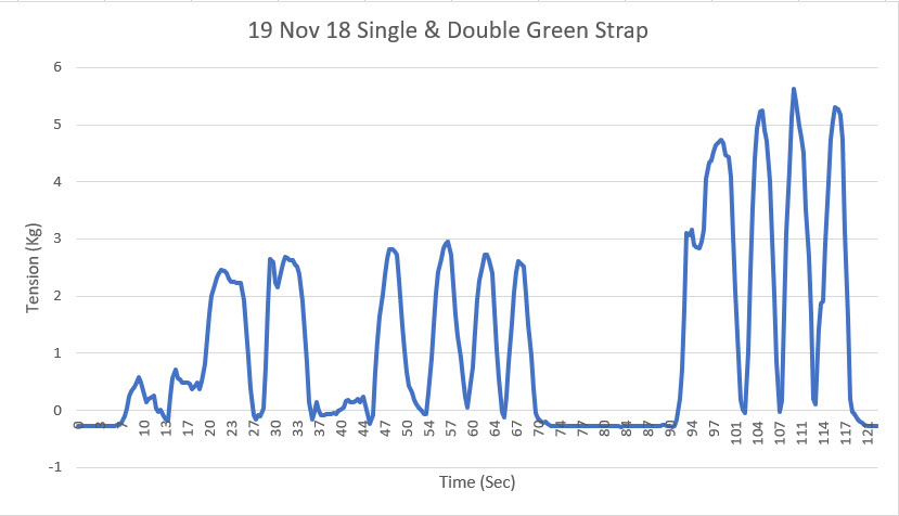
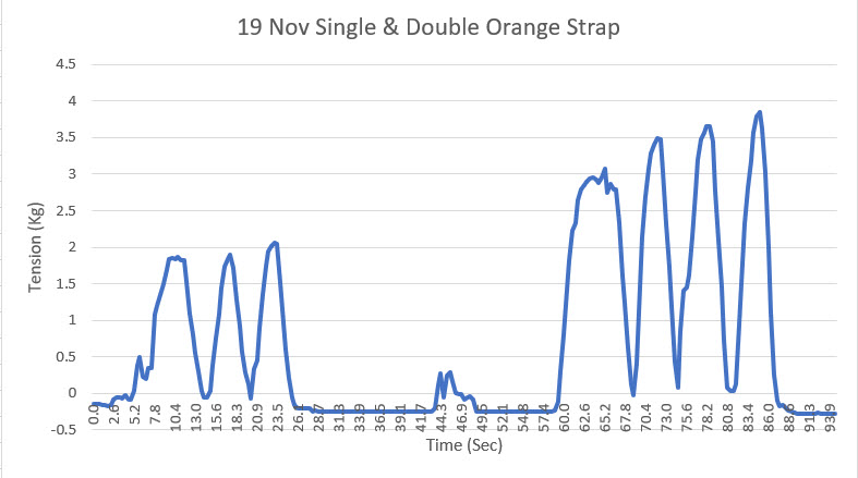
Then, at the request of my physical therapist, I measured the real-time tension for single & double orange straps, and single/double green straps, as shown below

Single and double green strap tension vs time

Single and double orange strap tension vs time


Stay tuned!

Frank


Digital Tension Scale

Posted 27 October 2018

I recently underwent rotator cuff repair surgery on my left (dominant) shoulder, and am now starting the rehab process.   My PT person was adamant that I not re-start my normal rowing routine for at least six weeks post-op, due to the possibility that I could re-tear the tendon.   This made me curious as to what the tension really was on my arms when rowing, so I decided to try and build a digital dynamic tension sensor, capable of plotting rowing strap tension in real time.

To start, I had to educate myself on the world of strain gauges and load cells, and what the differences are.   As I came to understand, what I wanted was a  load cell configured for tension measurement, with a  strain gauge as the active sensing element in the load cell.   So, I started searching for load cells, and was immediately inundated with ‘too much information’.   This deluge is certainly better than the old days where I had to search through paper (really, no internet!) magazines and catalogs, but at least you didn’t have to worry about overload headaches! ;-).

Anyway, I found this item ‘Degraw 40Kg Tension Load Cell and HX711 Combo Pack Kit‘, as shown in the screenshot below

Amazon catalog item for Degraw load cell

This looked perfect for my intended use, as I could hook one end onto my rowing machine strap, and connect some sort of handle to the other end.   Now all I had to do was figure out how to hook the thing up and get it to work.   Fortunately Degraw also provided a sketch of the hookup using an Arduino Uno, so that part was pretty easy.

Degraw-provided hookup diagram

After a bit more research, I found a nice HX711 library by bogde and some example programs, and got the whole thing to work using an Arduino Mega 2560.   Once I got a program running with some preliminary (but believable) results, I started thinking about how I was going to manage the physical aspects of hooking this assemblage to the rowing machine and recording dynamic tension.   I couldn’t really just let the HX711 board hang by the strain gauge wires while connected with jumpers to the Mega board, as the #28 strain gauge leads would surely break.   So, I came up with the idea of somehow attaching the HX711 board and a small microcontroller to the load cell assembly, and then connecting the whole thing to my laptop with a USB cable.   Hopefully the USB cable would be long enough to allow full extension of the rowing machine strap so I could collect full rowing cycle data.

After some digging around in my parts cabinets, I came up with two candidates for the ‘small microcontroller’ part of the plan; a 3.3V Teensy 3.2, and a 5V/16MHz Sparkfun Pro Micro.   I tried the Pro Micro at first, and almost immediately went down the rabbit hole (my term for getting lost in some technical wonderland without a clue how to get back) trying to figure out how to program the device – a challenge due to the way it handles com ports through the USB connector (it actually implements two different ones, depending on whether the boot loader or the user firmware is running – yowie!).   After climbing my way out of the rabbit hole, I decided to try the Teensy 3.2 instead, as I familiar with it from several other projects.   With the Teensy, I got a test program running and started taking data with known weights attached to the load cell. The way I did this was to suspend a plastic bucket from the load cell, and poured water into the bucket one liter (1Kg) at a time while recording data.   This was successful because I got good data, but unsuccessful because the data didn’t make much sense, as shown in the plot below

Results of pouring 1L (1Kg) water at a time into bucket suspended from load cell, using a 3.3VTeensy 3.2

As can be seen, the data was anything but the stairstep function I was expecting to see.   At this point I wasn’t sure if I had a hardware problem or a software problem, or something else entirely, so I sent an email to Degraw Product support with the above plot attached, asking if they had any insight into the problem.   Amazingly, they replied almost immediately, and offered to send me another load cell unit gratis so I could eliminate their hardware as the cause of the problem.   Although I was quite pleased with their offer of support, I thought maybe the 3.3V supply of the Teensy 3.2 might be causing the non-linearity (the HX711 advertises 2.7-5V operation but the lower voltage might be causing output linearity problems).   So, I tried again with the Sparkfun Pro Micro, and this time I managed to make the programming magic work. Then when I did the same test as above with the 5V Pro Micro instead of the 3.3V Teensy, I got the plot shown below.

Tension vs time plot created by pouring 1L (1Kg) of water at a time into bucket suspended from load cell, using Sparkfun 5V Pro Micro

So, now that I had the software and microcontroller problems solved, I started working on the mounting issue.   After a few minutes in TinkerCad and some quality time with my PowerSpec 3D PRO 3D printer, I had a mounting platform that clipped onto the two vertical rods in the ‘S-shaped’ tension load cell, as shown in the images below.

Reverse side of assembly, showing mounting plate clips attached to load cell vertical members

Sparkfun Pro Micro and HX711 board mounted on load cell

After getting all this set up, it was time to take some real data. Since I was still in the ‘no rowing’ zone after my surgery, I enlisted my lovely wife to do the honors while I recorded the data.   We have an Avari magnetic rowing machine, which thankfully doesn’t make much noise.   I recorded a total of 12 rowing cycles on two different ‘wave’ settings (I’m still not sure what the different ‘wave’ settings mean) at the lowest tension level, with the results shown below

As shown in the above plot, the peak tension reading was around 18Kg (about 40 lbs).    I’ve included a short video of the test below.

State memory for Wall-E2 – writing telemetry packets to FRAM

posted 28 September 2018

In previous posts, I have described my effort to give time, memory and relative heading super-powers to Wall-E2, my autonomous wall-following robot.   This posts describes a helper class I created to allow Wall-E2 to periodically write its current operating state to FRAM memory, for later readout by his human master(s), and a small test program to verify proper operation of the helper class.

My current conception of Wall-E2’s operational state consists of the current time/date, its tracking mode and submode, and the current left, right, and forward distances, and the current battery voltage. These parameters have been encapsulated in a CFramStatePacket class with methods for writing state packets to FRAM and reading them back out again.   The complete code for this class is shown below. Note that all the class code is contained in just one file – FramPacket.h.   There is no associated .cpp file, as I didn’t think that was necessary.

To test my new CFRAMStatePacket class, I created a small test program that periodically writes simulated state packets to FRAM using the helper class methods, and optionally (if the user creates an interrupt by grounding the appropriate pin) reads them back out again.   This program is designed to run on an Arduino Mega 2560.   If a Uno is used, the interrupt pin number would have to be changed.

The test code also looks for a low on the  CLEAR_FRAM_PIN (Pin 3) on startup.   If it finds one, it will clear  NUM_FRAM_BYTES_TO_CLEAR (currently 2000) FRAM bytes and then read them back out again, byte-by-byte.   Otherwise, the program will continue storing state packets where it left off the last time it was powered up.   Here’s the test code:

And here’s some output from a typical run:

And here is an Excel plot showing the simulated values

Plot of the simulated values generated by the test program


So now I have a way for Wall-E2 to write a minute-by-minute diary of its operating state to non-volatile storage, but I don’t yet have a good way to read it all back out again.   That’s the next step – stay tuned!

01 October Update:

I created a small program to read back telemetry packets from FRAM.   When I want to see what  Wall-E2 has been up to, I will replace his normal operating firmware with this sketch, which will allow me to read out all or parts of FRAM contents.   The sketch is included below:

and a typical output run is shown below.   Note that this program decodes the stored 4-byte unix time value into human-readable date/time format.   And yes, I know it’s in that funny ‘American’ mm/dd/yyyy format, but I’m an American, so … ;-).


Frank


Integrating Time, Memory, and Heading Capability, Part VIII

Posted 13 September 2018

Now that I have worked out most of the problems associated with the MPU6050 6DOF IMU module, it was time to integrate the new heading-based turn algorithm into the main Wall-E2 operating system.   As I have done in many past projects over the last half-century or so, I started this process by documenting the entire OS, with particular emphasis on how Wall-E2 currently navigates around his world.   When I started doing this in the 1970’s, the medium I used was an MIT Engineering notebook, hand-written in ink.   Over the ensuing decades the medium has changed, but not the basic idea – the process of putting coherent sentences and paragraphs onto paper (or screen) forces me to think through what is – and is not – important/true.   I have solved many a seemingly intractable problem not with an oscilloscope or debugging tool, but by simply writing things down.   In the current iteration of this process, I use Microsoft Word (not for any particular reason, except that it is available and familiar)   initially, and then dump the results into a post like this one – see below ;-).


Description of FourWD_WallE2_V1 Navigation Algorithm

09/04/18

At the start of each pass through loop(), the software determines the current OPMODE given the current environment and the immediately previous OPMODE.   The existing OPMODEs are NONE, CHARGING, IRHOMING, WALLFOLLOW, and DEADBATTERY

  • NONE: Default OPMODE when no other mode can be found to apply to the situation.   As of this writing, the only use for this OPMODE is to initialize the PrevOpMode and CurrentOpMode loop variables in Setings()
  • CHARGING: set in GetOpMode() if the charger is physically connected (CHG_CONNECT_PIN goes HIGH) and the CHG_SIG_PIN is active (LOW). In the CurrentOpMode Switch the PrevOpMode is also set to CHARGING (so that both prev and current op modes are CHARGING), the motors are stopped, and MonitorChargeUntilDone() is called.
    • MonitorChargeUntilDone() blocks until charging is complete, or the BATT_CHG_TIMEOUT value is reached or the charger is physically disconnected (manually pulled out for some reason).
  • IRHOMING: Set in GetOpMode() when the call to IRBeamAvail() (checks IR beacon signal strength) returns TRUE.   In the CurrentOpMode Switch the PrevOpMode is also set to IRHOMING (so that both prev and current op modes are IRHOMING).   A blocking call is made to IRHomeToChgStn() with an Avoidance Distance’ of 0 for hungry’ or 30cm (for full- no need to charge’. The idea here is that in the full’ case, the robot will continue to home until near the charging station, and then break off.
    • IRHomeToChgStn(): sets up a PID and enters a loop, exited only when either the charger connects, or the robot gets stuck or it gets too close to the charging station (this can only happen in the full’ case).   Is Stuck’ is determined in IsStuck() if the front distance variance gets too small (i.e. the front distance isn’t changing).
  • WALLFOLLOW: This is the OpMode that is assigned by GetOpMode() when none of the other mode conditions apply. IOW, this is what the robot does when it isn’t doing anything else.   In the WALLFOLLOW Case section of the CurrentOpMode Switch, the wall-following operation is further broken down into a TrackingCase Switch, with   TRACKING_LEFT, TRACKING_RIGHT, TRACKING_NEITHER sub-modes, with state mode variables maintained for both the current and previous tracking modes.   Each time through the loop(), the various tracking cases make one adjustment to the left/right motor speeds. there are no blocking calls at all in the entire WALLFOLLOW section, with the exception of the BackupAndTurn()’ calls in the TRACKING_LEFT and TRACKING_RIGHT cases when an obstruction or the stuck’ condition is detected.
    • BackupAndTurn( bool bIsLeft, int motor_speed): The idea here is for the robot to back up and do a course change to extract itself from some situation. Up until now, this has been accomplished by making a timed turn one way or the other, but this hasn’t worked well because the correct time for turning on carpet is wildly different than the correct time on hard flooring.   The new heading sensor is intended to solve this problem.
    • Now that Wall-E2 can make accurate turns, the question becomes “what’s the best way to do obstruction-avoidance or stuck-recovery turns?”. If Wall-E2 is following a wall when it gets stuck, maybe it should back up slightly and try to go around, or maybe it should just turn around and go back the way it came.   Maybe a simple obstruction should be treated one way, but a stuck’ condition treated another?   The go back the way I came’ model is simple enough but might result in an uninteresting ping-pong’ shuttle track where it stays until it runs out of battery.   A more complex response might allow the robot to go around obstacles and continue its journey?   Maybe it backs up slightly (wall-following in reverse, maybe?), and then makes an X degree turn away from the wall, runs straight for a second, and then starts wall following again.

09/05/18

The current BackupAndTurn()’ routine takes bIsLeft, a Boolean representing the current tracking direction (left or right) and a motor speed.   All it does is call RollingTurnRev(bIsLeft, 1500), where 1500 is the time in millisecond to run the motors.

RollingTurnRev() just calls RunBothMotorsMsec() with the motor speed on one side set to MAX and on the other to OFF (we know this won’t work on Wall-E2, because the wheelbase is too wide – he just locks up.

RollingTurnRev() is called in two places; ExecDiscManeuver() and   BackupAndTurn(). BackupAndTurn() is called from 4 places;   TRACKING_NEITHER/RIGHT/LEFT, and IRHomeToChgStn().   In all these cases, the robot knows which (if any) wall is closer, so it can execute the proper rolling turn

From what I see so far, it appears all these cases can be handled by a turn routine that does the following:

  1. Moves straight backward for just a second or so (or maybe even less)
  2. Makes a 45 ° forward rolling turn away from the nearest wall. If there is no nearest wall, go opposite the way it went last time (requires a global Boolean to save this value)
  3. Makes another 45 turn in the opposite direction to the first one.   This will have the effect of a side-step maneuver, as shown in this post.

After this review, it was clear that all I had to do to integrate the new heading-based turn capability into Wall-E2’s OS was to replace the RollingTurnRev() function with a new ‘RollingTurn()’ function that takes flags for FWD/REV and for CCW/CW, and a parameter for the number of degrees to turn.   Since I had already demonstrated all the code blocks in stand-alone test programs, all I had to do was copy the appropriate code pieces into the appropriate spots in Wall-E2’s OS, and then spiff things up a bit here and there.   When I was done, I had a single function that could facilitate a range of maneuvers.

To test the newly integrated capability, I added some code to Wall-E2’s setup() function to perform a series of S-turns, each of which demonstrates a typical avoidance maneuver. For convenience, I told Wall-E2 to execute a ‘K-turn’ reversal and then S-turn his way back to me.   As can be seen in the following short video, this worked fairly well!

Now that I have the basic heading-based turn capability integrated into Wall-E2, the next step will be to demonstrate that Wall-E2 can use its new superpowers to avoid obstacles in ‘the real world’ (as real as it gets for Wall-E2, anyway).

Stay tuned!

Frank