Tag Archives: IR Follower

Charging Station System Integration. Part II

Posted 07 April 2017

After getting the wall-following mode re-implemented in the ‘new-improved’ Wall-E2 operating system, I re-enabled the IR homing part of the code, only to discover that Wall-E2 thought it could see the IR homing beam  everywhere, in the atrium, even though the IR homing LED wasn’t even in the room (and was turned OFF, besides)!  This didn’t make a whole lot of sense, until I realized Wall-E2’s sensors were ‘seeing’ IR from the overhead floodlamps.  I confirmed this by having my ‘lovely assistant’ wife turn the atrium lights on & off and monitoring the detector outputs.  Same thing for the entry hallway (see data below)

I thought I had solved this problem way back when I first started working with the IR detection/homing idea back in October of last  year.  In that initial post  where I investigated  the  OSEPP IR Light Follower’, I found I had to turn OFF the LED track lights in my lab in order to avoid swamping the detector array.  Over the next month or so this project evolved into a custom designed array of  Oshram SFH309FA-4 phototransistors (see  http://gfpbridge.com/2016/11/ir-light-follower-wall-e2-part-vi/), and as part of this I discovered that the Oshram devices weren’t at all sensitive to the LED track lighting in my lab.  From this I concluded (erroneously as it now turns out!) that I didn’t need a ‘sunshade’ at all, which allowed for a much simpler installation on the robot (see  http://gfpbridge.com/2016/11/ir-light-follower-wall-e2-part-vii/).  Finally, when this module was transferred from the 3-wheel test bed to the Wall-E2 and combined with the charging status display panel, we arrived at the ‘final’ arrangement shown in the following photo

IR detector module (red) shown beneath charging status display panel (blue)

This worked great for all my in-lab IR homing tests with my all-LED overhead track lighting, but as soon as I started testing out in the rest of the house, the overhead incandescent and halogen lamps swamped out the detectors. So, it was back to the drawing board – again :-(.

The first thing I did was to confirm that the IR detectors were indeed getting swamped by the overhead lighting, and that it was possible to prevent this by some sort of shielding.  I started with a wrap-around cardboard shield that completely covered the IR detector module, as shown below, and placed the robot on the floor of the entry hallway in a normal ‘wall-following’ position

Sunshade V0. Not very practical, but does set the baseline for the rest of the tests

Test position for 07 April 2017 sunshade tests


With this setup, Wall-E2 was pretty much deaf to the overhead lamps, showing no reaction to cycling the lights.  Of course, this configuration would also completely prevent it from detecting the charging station IR beam, but….

Next I modified the above V0 cover to allow a bit more visibility, as shown below:

Sunshade V1 oblique view

Sunshade V1 front view

This version is still a bit too restrictive for normal IR beam detection/homing, but was worth a shot for testing purposes.  With this setup, the overhead lighting  is noticeable, as shown below.

Sunshade V1 at sunshade test position. Lights ON four times for 5, 5, 5 and 10 sec

As can be seen from the plot, the V1 sunshade responds to the overhead lamp IR with an average A/D reading about 700 out of 1024.

Next, I modified  the sunshade again so that it would just allow the IR detector module to ‘see’ straight ahead, on the theory that that would be the minimum requirement for successful IR beam detection/homing.  With this setup, the overhead lamp response was stronger, but still not completely overbearing;  the IR detector response to the overhead lights averages A/D values of about 600 out of 1024.

Sunshade V2 oblique view

Sunshade V2 front view.  Note IR detectors visible from directly in front

IR detector response to overhead lamps. ON three times for 5 sec each

When I ran a homing test  with the V2 sunshade in my lab (with LED overheads, not incandescent), the robot homed successfully from about 1 m away, with the following IR detector/homing performance

In-lab (LED overhead lighting) charging station homing performance with V2 sunshade

In the above homing test, the IR detector values started out at approximately 900, 200, 450 and 750, respectively.  This means I could set the IR beam detection threshold at, say, 400 and still have a 200-count noise margin in both directions (200 down from the overhead IR flooding value, and 200 up from the typical 1-meter IR beam intensity).  From the movie it is obvious that the minimum IR reading is switching back and forth between at least two detectors, so I think it is safe to say that IR homing would occur even in the presence of a 600 unit noise level, as the 200 or lower reading switched between detectors.

Next, I moved the charging station into the entry hall so I could test IR homing performance with the overhead lights on and off.  My prediction was that Wall-E2 should be able to home successfully in both cases.  For the test, the charging station lead-in rails were oriented in the preferred ’tilted’ orientation, as that should give the best homing performance, as shown in the photos below:

Hallway IR homing test setup

Robot shown in captured position. Note lead-in rail ’tilt’ relative to the wall

I made three runs; Lights ON, lights OFF, and Lights ON, as shown in the three video clips below:


As can be seen in the videos, Wall-E2 successfully homed to the charging station with the overhead lights OFF, but not with them ON – bummer!

So, further testing will be required to determine the particulars of the two failed runs, and what – if anything – can be done about it.

After moving my laptop  out into the hallway so I could capture telemetry from the robot while also filming the runs, and checking everything out, I made two successful IR homing runs – one with the overhead lights ON, and another one with them OFF.  I captured telemetry from both runs, and was clearly able to distinguish between the lights ON and OFF scenarios.  The videos and the telemetry plots are shown below:

08 April 2017 Hallway Test2 with V2 Sunshade – Lights OFF

08 April 2017 Hallway Test2 with V2 Sunshade – Lights ON

From the above plots, the lights ON & OFF conditions are readily recognizable.  In the ‘OFF’ condition, the ‘background noise’ is at about 600-700, and the IR beam is at 100-200.  In the ‘ON’ case, the noise level is higher (lower count), at about 150-250, but the IR beam is lower too – around 50-150.  I guess this makes some sort of sense, as the IR energy from the charging station beam is a separate, additive source relative to the overhead lighting.  Also, both plots show good motor response curves – the left & right motor speeds are obviously being adjusted rapidly in response to IR detector changes.

So, at this point I’m pretty convinced that the V2 sunshade is working, so I plan to print up a permanent version that will (hopefully) simply slide on to the front of the existing charge status display panel.

Stay tuned!

Frank


Charging Station Design, Part XI – PID Tuning

Posted 14 March 2017

As I was doing the IR homing tests described in my last post, I noted that Wall-E2 wasn’t all that great at homing; in particular it missed the opening in the lead-in rails on several occasions, instead hanging up on one side or another.  This was a bit mystifying to me, as I thought I had the homing code working very well with my old 3-wheel robot (see ‘IR Light Follower for Wall-E2, Part X – More PID Tuning‘).  At the time, I decided to use one of my best scientific research tools and simply ignore the problem, hoping it would either go away, or my subconscious mind (by far smarter than my conscious one!) would figure it out in the shower or while drifting off to sleep.

And, in fact, last night while drifting off to sleep, I remembered that the PID tuning for the 3-wheel robot had to take into account the fact that  even small  differences in drive wheel speeds get magnified by the free-castering front wheel.  Wall-E2, with its all-wheel drive  behaves entirely differently, and since small wheel speed differences don’t get amplified into big directional changes, the PID tuning parameters appropriate for the 3-wheel version are too passive for the 4-wheel one.

So, I went back to the drawing board (again!) for PID tuning for the 4WD Wall-E2, starting with the current 3-wheel parameters as the ‘too passive’ baseline.  From my previous article, the final PID parameters were P = 0.1, I = 10, D = 0.2, with the input scaled by 1, 5, or 10 depending on IR beam signal strength.  My initial thought is that the 4WD robot needs a lot more ‘D’ (differential) to increase its turn rate with respect to IR beam heading changes, so I tried a couple of runs with the D value increased from 0.2 to 2 (factor of 10 increase).  As the following video shows, this did seems to increase Wall-E2’s agility somewhat, but still not enough to overcome even minor initial heading offsets, especially to the left.

After some more testing with different values of P,I,D, I began to wonder if I might be having problems with the basic IR detection hardware and homing software, independent of the PID tuning issue.  When I did the previous PID study, I also captured the raw detector data, which allowed me to determine how the PID tuning and the basic detection hardware/software were interacting.  I may have to go back and do that again with the 4WD setup

Stay tuned,

Frank


Charging Station Design, Part X

Posted 11 March 2017

The last few days have been spent partially implementing the software structure and state design described in my ‘Wall-E2 Operating Mode Review‘ of 06 March.  Up to this point, the only thing Wall-E2 knew how to do was wall-following, but there were (and still are) a number of ‘sub-modes’ associated with wall-following.  Now all of this code has to be grouped into the  ‘Wall-Following’ state/function under the main program, and the new ‘Charging’ and ‘IR Homing’ state/functions added.

For purposes of testing, I decided to basically comment out all the wall-following code and concentrate on the IR Homing and Charge modes.  To do this, I added the new operating mode determination and top-level case switching code at the top of ‘loop()’, and left the MODE_WALLFOLLOW: case un-implemented.  the MODE_CHARGING code is all new, but the MODE_IRHOMING code was copied from my previous work with the 3-wheel robot last November.

After getting most of the MODE_CHARGING and MODE_IRHOMING code implemented, I ran some bench tests to see how well things work.  After finding and fixing a number of typos, logic errors, and downright goofs, I was able to video a successful IR home to charge, followed by a charge-completion  disconnect (instead of waiting for a full charge termination, I tied execution to manual charge plug disconnect).  Here is the video


A couple of side notes from the above video

  • It is evident that the IR homing with PID works very well, to the point where the lead-in side rails almost aren’t needed (but only ‘almost’, I fear)
  • The fixed charging station fixture isn’t quite high enough.  In order to more accurately line up with the center of the charging port, I had to raise the fixture by about 5mm
  • The disconnect routine backs up far enough, but doesn’t quite make a complete 90 º turn.  I should be able to tweak the turn duration a bit to make that happen.

So, at this point, I think I have most of the new parts of the operating system working, although some parts are hard to test due to the long charge times.  Here’s what I think remains to be done:

  • Reconnect and test the LIDAR and ping sensor hardware; this will be required to test wall-following and the charge station avoidance sub-mode
  • Reprint the charging station fixture with 5mm more height
  • Set up the full lead-in rail arrangement and confirm proper homing/engagement, along with proper dis-engagement, and proper avoidance when the battery isn’t low.
  • re-implement and test the wall-following code in the new structure, as MODE_WALLFOLLOW.  This  should be just a bunch of cut-and-paste operations.
  • test the various ‘normal’ state transitions; wall-follow to IR homing to charge monitoring to wall-following
  • test the wall-follow to IR homing to charge station avoidance transition.
  • fully test the end-of-charge scenario.

12 March Update

I reconnected the LIDAR and ping sensor hardware, and confirmed (not without some wailing and gnashing of teeth!) proper operation.

I reprinted the charging station fixture with a 5mm pedestal, and transferred the LED/charging plug from the old fixture to the new one.

Set up the lead-in rails on my benchtop so that I could test both the ‘hungry’ and ‘not hungry’ IR homing scenarios.

Tested the ‘not hungry’ scenario by setting the ‘full’ threshold back down to 7.4V (50% charge, per http://batteryuniversity.com/learn/article/lithium_based_batteries).  The following video shows one of the test runs:


13 March Update:

After a bunch of software and hardware bugfixes, I think I finally have the ‘home to charge’ scenario working, as shown in the following video clip and edited telemetry capture:

The significant parts of the video are:

  • The POST test  in the first few seconds
  • The successful IR homing operation
  • The successful charger plug engagement.  When the robot senses the charger plug, it commands the motors to stop.
  • Just after the charger plug engages, the charger’s battery relay is enabled, which disables power to the motors (note the red motor controller power LED goes OFF).
  • For this test, the BATT_CHG_TIMEOUT_SEC parameter was set to 10 seconds.  Rather than wait the entire 10sec, all but the first few and last few seconds were clipped.  Note that after the 10sec timeout, the robot disables the charger relay which re-applies motor power to the robot (note the red motor controller LED is re-enabled), and the robot backs off the charger plug.
  • The robot now backs completely clear of the lead-in rails, and turns away from the nearest wall before going back to wall-following mode.

I have also posted an edited version of the telemetry captured during this test.  As you can see, the robot transitions to IR homing mode, successfully homes on and engages with the charging plug, monitors the charging process, an then executes the ‘ExecDisconManeuver()’ to disengage from the charger and back out of the charging station area.

Loader Loading...
EAD Logo Taking too long?

Reload Reload document
| Open Open in new tab

Download


Stay tuned,

Frank


Wall-E2 Operating Mode Review

Posted 06 March 2017

At this point in the 4WD robot’s development, I think it might be time to review all of  Wall-E2’s different operating modes, and  what external sensor conditions determine which operating mode is active.  Previous to this point, the robot had only one operating mode – the ‘Wall-Following’ mode.  Now that the new battery pack has been added, along with the new capability for homing in on an IR beam to connect to a charging station has been added, the robot operating system must be enhanced to manage the additional operating modes.

Operating Modes/States:

  • Wall-Following:  This is the ‘normal’ operating mode, active when nothing else is going on (no IR beam present, no charging voltage present)
  • IR Beam Homing: Occurs when an IR beam is detected.  In this mode, a PID controller determines wheel speeds in an attempt to home in on the IR source.  This mode has two distinct sub-modes, depending on the battery state of charge.  if the battery is relatively full, then the front obstacle avoidance distance is  increased such that the obstacle avoidance turn will occur before the robot gets captured by the lead-in side rails.  Otherwise, the obstacle avoidance distance is disabled entirely, allowing the robot to be captured and the charging connection to be made
  • Charging:  Occurs when the robot is connected to the charger.  In this mode, the charging status lines are monitored to detect end-of-charge (EOC).  When EOC is detected, the robot backs straight out of the lead-in rail area, and then turns 90 º away from the nearest wall and transitions to wall-following mode.

Here is a draft state-transition diagram for the system

Loader Loading...
EAD Logo Taking too long?

Reload Reload document
| Open Open in new tab

Download

As can be seen from the diagram, the system starts out in the POST (Power On Self Test) state, and transitions to one of the other states depending on sensor input.

  • If no IR beam is detectable, and the charging station is not connected, then the system transitions to the normal ‘Wall-Following’ state.  The wall-following state continues until either an IR beam is detected, or  a physical connection to a  charging station is detected.  The normal exit condition from the wall-following state is via detection of an IR beam, which causes transition to the ‘IR Homing’ state.
  • In the IR Homing state, there are two possible behaviors; if the battery is more than 3/4 full (not quite sure how I’m going to define that, but…), then the robot will actively avoid the charging station by performing an obstacle avoidance 90 º degree turn at a  front distance larger than the extent of the charging station lead-in gate, and transitioning back to the ‘Wall-Following’ state.  If the battery is less than 3/4 full and a charge is desired, then the robot will continue to home in on the IR beam until a physical connection to the charging station is detected, whereupon the system transitions to the ‘Charging’ state.
  • In the Charging state, the system monitors the charging status signals, waiting for both ‘Fin1’ and ‘Fin2’ signals to become TRUE.  When this happens, the robot  backs out of the charging station lead-in gate area, executes a 90 º turn away from the nearest wall, and transitions back to the ‘Wall-Following’ state.

Here is a first cut at a system software structure chart that incorporates the above modes/states

Loader Loading...
EAD Logo Taking too long?

Reload Reload document
| Open Open in new tab

Download

Wall-E2 Charging Station Design, Part VIII

Posted 18 January 2017

In my last post on this subject, I had discovered  two major problems with my current strategy to free Wall-E2 from the need for human assistance.  The first problem was how to get Wall-E2 disengaged from the charging station, and the second was how to transition from charging power to on-board battery power without going through a power-cycle reboot.  As noted there, I decided there were two things I needed to do – install a MOSFET switch in the coil circuit so I could switch the relay back from ‘charge’ mode to ‘run’ mode before the external +5V charging voltage disappeared, and to connect the external +5V charging voltage through a blocking diode to the Arduino Mega’s +5V buss so the controller could continue to operate while the batteries were charging.

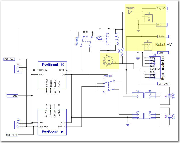
So, I made the above changes to the charger module, as shown in the image below (changed areas highlighted). For reference, the ‘original’ schematic has also been included

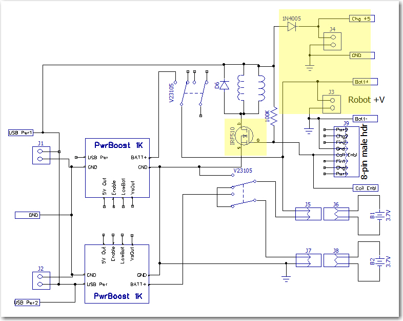
Dual Cell Charging Module with changes highlighted

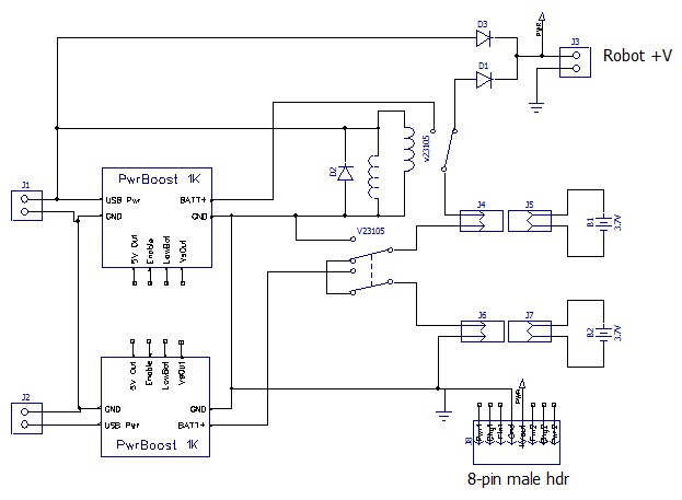
Dual cell balance charger. Note the two Axicom relays ganged to form the required 3PDT switch

As can be seen above, there are two major changes

  • Added a  IR510 n-channel enhancement mode MOSFET to control relay coil current via a new ‘Coil Enable’ signal rather than directly from the external +5V line.  A 100K pullup was added so that the default configuration of the MOSFET switch was ‘ON’.  A LOW signal on the ‘Coil Enbl’ line will switch the MOSFET to ‘OFF’, thereby switching the 3.7V cells from ‘charge’ (parallel) to ‘run’ (serial) mode.
  • Removed the blocking diode from the +7.4V ‘Robot +V’ line, and added a separate ‘Chg +5’ 2-pin terminal with a blocking diode.

After making these changes,  I set up an experiment where I could simulate the process of connecting the robot to the charger (thereby switching the batteries from the ‘run’ (serial) to ‘charge’ (parallel) configuration, with Arduino power being supplied by the external +5V line, and then disconnecting it using the new MOSFET circuit to switch the batteries back to ‘run’ (series) configuration before mechanically disengaging the external +5V plug.

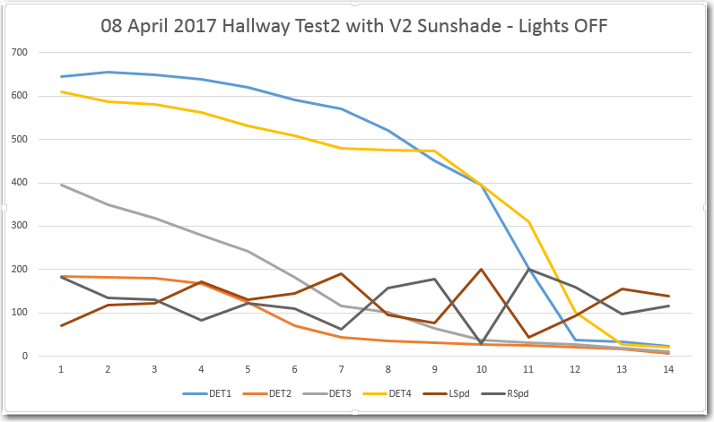
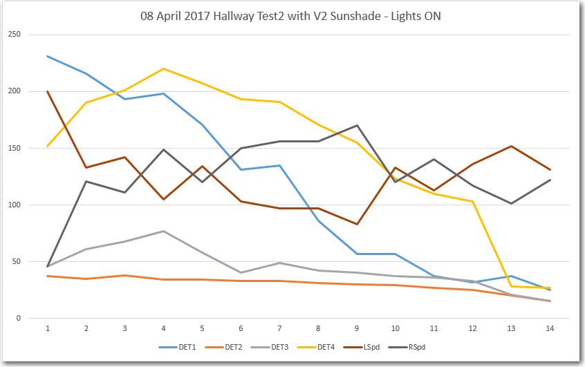
Before conducting the experiment, I wanted to confirm that  the reboot problem still existed.   I set the robot up a small block so the wheels were off the ground, turned on the main power switch, waited while the robot booted up and the wheels began to turn (the program was configured  for continuous half-speed motion), and then engaged/disengaged the external +5V charging plug.  As expected, when the plug was engaged the wheels stopped turning but the Arduino continued to operate (confirmed by noting that telemetry readouts continued uninterrupted).  However, when I disengaged the plug, the wheels started turning again immediately, and the telemetry readouts continued unabated, indicating that no power-cycle reboot had occurred!  I ran this experiment several more times with the same result – after making the above changes, I could not get the robot to reboot in either direction – from ‘run’ to ‘charge’ mode or from ‘charge’ to ‘run’ mode. Amazing!

OK, so what caused the different behavior?  When I ran this same experiment before the changes, I saw an approximately 50msec gap between the time the external +5V line went away, to the time when the Arduino +5V line was again stable due to the +7.4V power via the regulator block. AFAIK, there were only three significant changes made to the charging module:

  • The IR510 MOSFET was added to enable/disable  the coils under computer control, with a 100K pullup to keep it in the ‘ON’ (low resistance) mode by default.
  • The external +5V line and its associated blocking diode was removed from the ‘Robot +V’ terminal to a new ‘Chg +5’ terminal
  • The blocking diode between the battery stack and the ‘Robot +V’ terminal was removed

So, what’s the deal here?  AFAICT there are only two possibilities:

  1. I didn’t/don’t fully understand the mechanism producing the 50msec power gap in the previous configuration
  2. I don’t fully understand why the current configuration  doesn’t have a 50msec power gap

Previous Configuration:

I am 100% certain that I observed a consistent, repeatable power-cycle reboot when switching from external +5V to internal battery operation, and I got the 50msec number from scope measurements .  To make the scope measurements, I triggered the scope trace on the falling edge of the external +5V line, and measured the time lag from that trigger to the time that internal battery voltage was available to  the Arduino.  The reboot phenomenon was verified by noting the long (5-10 sec) delay between the time the external power was removed to the time when the motors started running again, and by watching the interruption on the Arduino serial port.  The 50msec or so gap is consistent with the idea that it takes some time for the relay coil field to collapse after external power removal, plus the time required for the relay contacts to physically move from the ‘engaged’ to the ‘disengaged’ contacts.  During this interval, the only thing powering the Arduino is the charge left in the 680 uF power supply filter cap.  Assuming a current drain of around 100mA, it would take only about 5-10msec to cause a 1-2V drop on the +5V buss.  With the measured current drain of about 68mA, I  measured about 30msec for a 2V drop using my trusty O’scope, so this all tracks.

Current Configuration:

In the current configuration,    after the 2V drop, the voltage drops only very slowly, so the current drain must also drop significantly – could that be the answer?  Maybe most, if not almost all of the measured current drain is the coils themselves – so that after the blocking diode gets reversed, the drain out of the filter cap goes down by an order of magnitude or so, thereby letting the Arduino live on until the internal battery takes over?  Lets see – the specs for the Axicom V23105A5476A201  relay show 30mA for the coil current, times two relays gives about 60mA total.  The measured current with the relays engaged was about 68mA, meaning that when the diode blocks, the drain from the cap goes from 68 to 8mA, meaning an additional delta of 1V (from about 4.5 to about 3.5) should take 680X10-6/8X10-3 = 85msec, which is reasonably close to what I’m seeing on my O’scope.

That’s my story and I’m stick’n to it!

OK, so now my story is this:  In the previous configuration, the Arduino 6800uF filter cap supplied relay current  all the way down to zero volts, which meant that the voltage across the cap (and consequently, the Arduino working voltage) dropped to below 3V in less than 20msec, well less than the time required for the internal battery source to take over operation.  In the new configuration, the blocking diode between the external +5V supply line and the Arduino isolates the Arduino from the charging circuit after a drop of about 2V.  After this, the Arduino  is powered solely by the 6800uF cap, but because the Arduino’s current drain is  much smaller than the 60-70mA required by the charging circuit, the cap can power the Arduino for another 100msec or so, which is plenty of time for the internal power source to come on line.

One implication from this story is that the MOSFET circuit may not have been required at all.  As evidence, the gate of the MOSFET is tied to external +5 through a 100K resistor, so by default it is ON (low drain-source resistance) all the time, unless deliberately switched from the Arduino.  During all this testing, that control line  has been left open, meaning the MOSFET is just sitting there, doing its best to emulate a short length of wire. However, I’m reluctant to take it out or deliberately short around it for three  very good reasons (actually only one good reason, and two  not-so-good ones); first, it is just barely possible that the MOSFET actually turns OFF at some point in the process, maybe hastening the relay change from energized to de-energized (that’s a  not-so-good reason).  Second, it is a major PITA to disassemble the robot down to the point where I can access the MOSFET and install the short (another not-so-good reason). Finally, even if I do properly understand what is going on now, it is still possible that increased Arduino loads in the future will cause the reboot problem to re-appear; in this case, being able to de-energize the relays before disengaging from the charger will be a life-saver (that’s the good reason).  In addition, I’m unwilling to screw around with something that appears to be working just like I want it to (in other words – “if it’s working, don’t screw  with it!!”)

Where to from here?

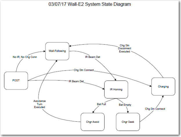
As it stands, I have a robot that can be charged through its front-mounted external power jack, and should be able to  (assuming appropriate information availability) switch to internal battery power and disengage itself from the charging station.  Now I need to actually implement the entire solution, generally as follows:

  • Confirm that the proposed engagement/disengagement strategy will actually work.  To do this, I’ll need to modify the operating software to
    • recognize when the external power plug has engaged and is supplying power
    • switch back from external to internal power
    • disengage from the external power plug.
  • Build up the fixed portion of the charging station, including mounting the IR LED and supplying 5V power
  • Simulate the entire IR track/side-rail capture/engagement/disengagement cycle on the bench
  • Modify the operating system to implement the required additional tracking/movement modes

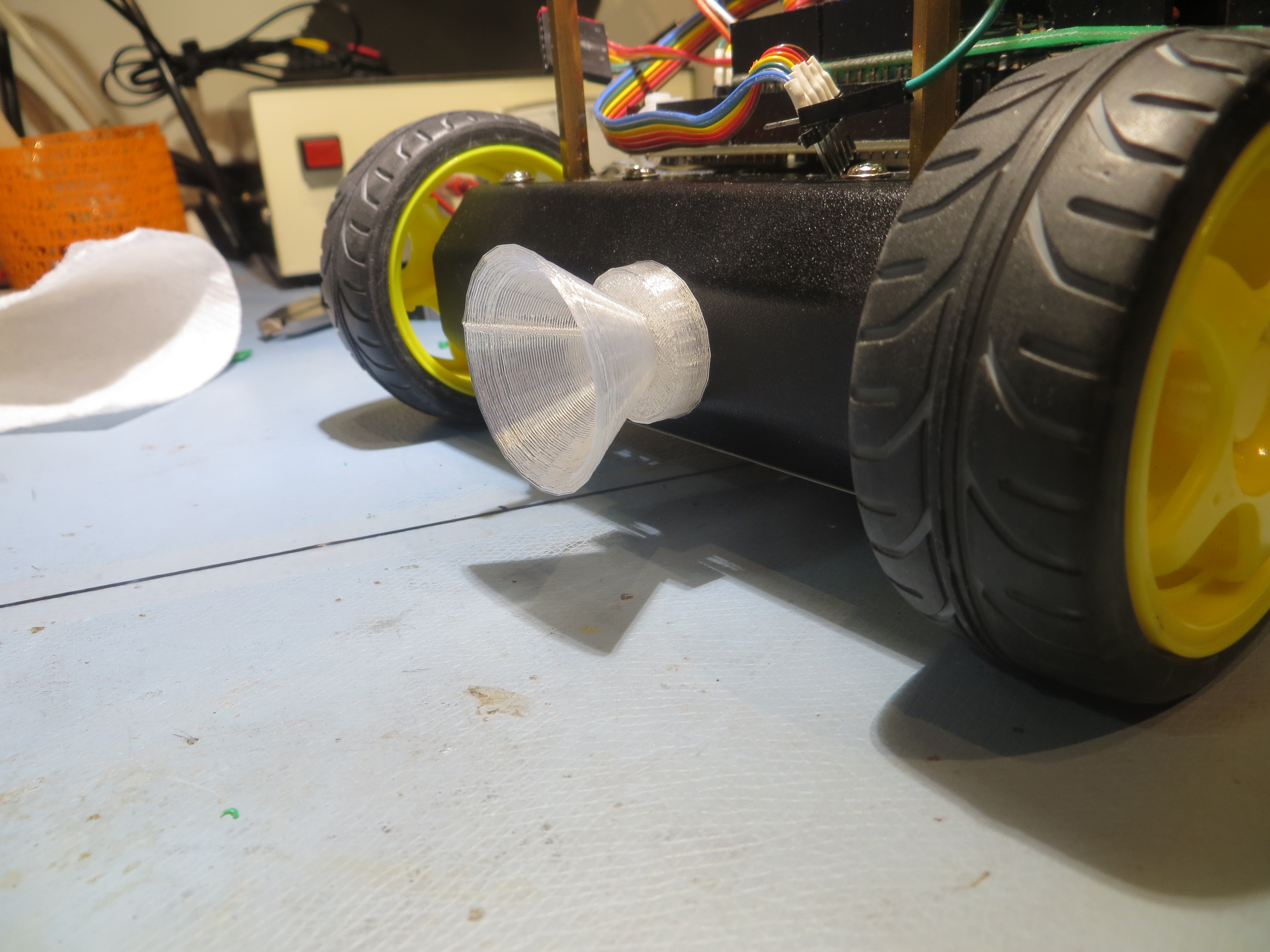
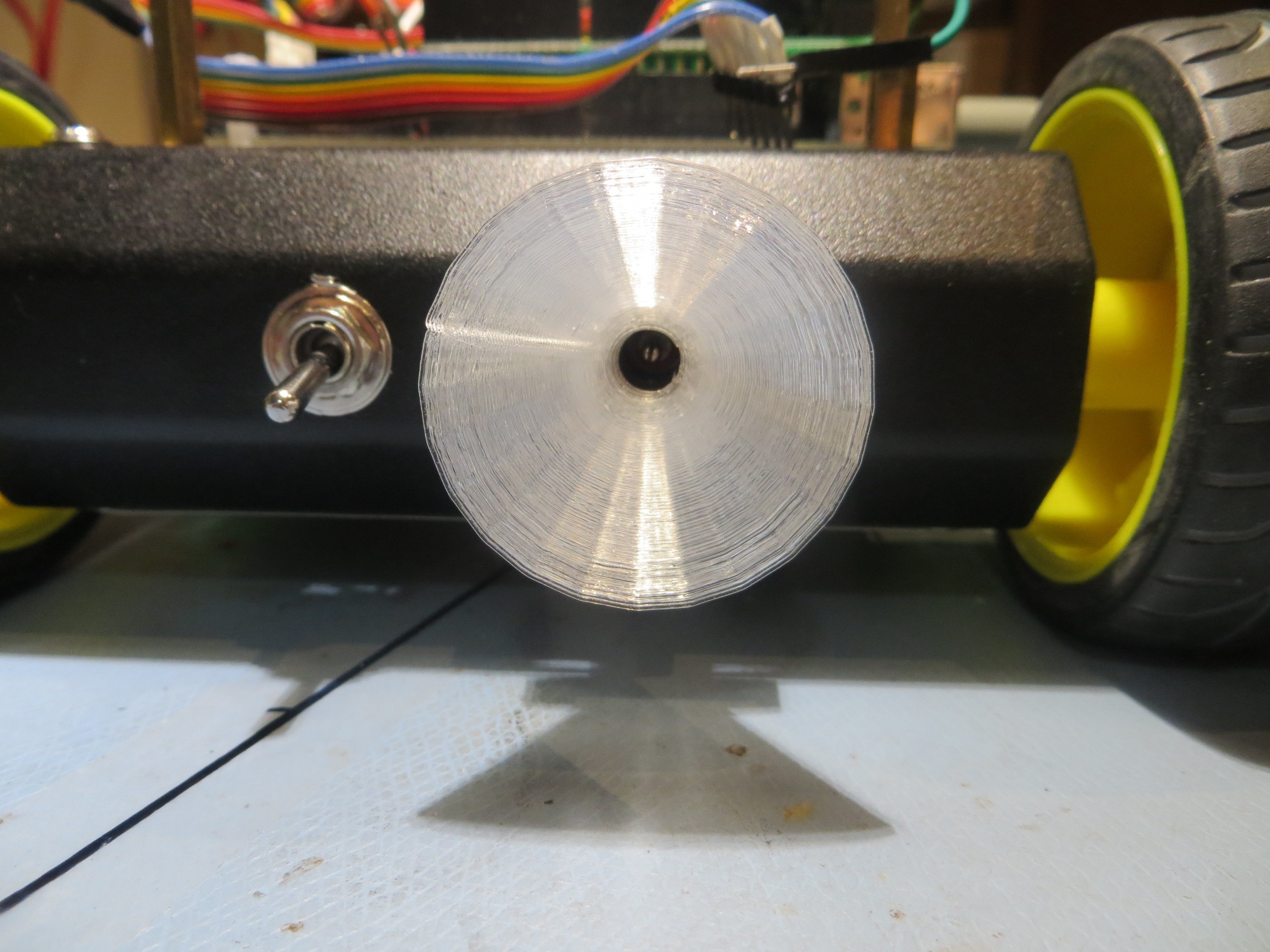
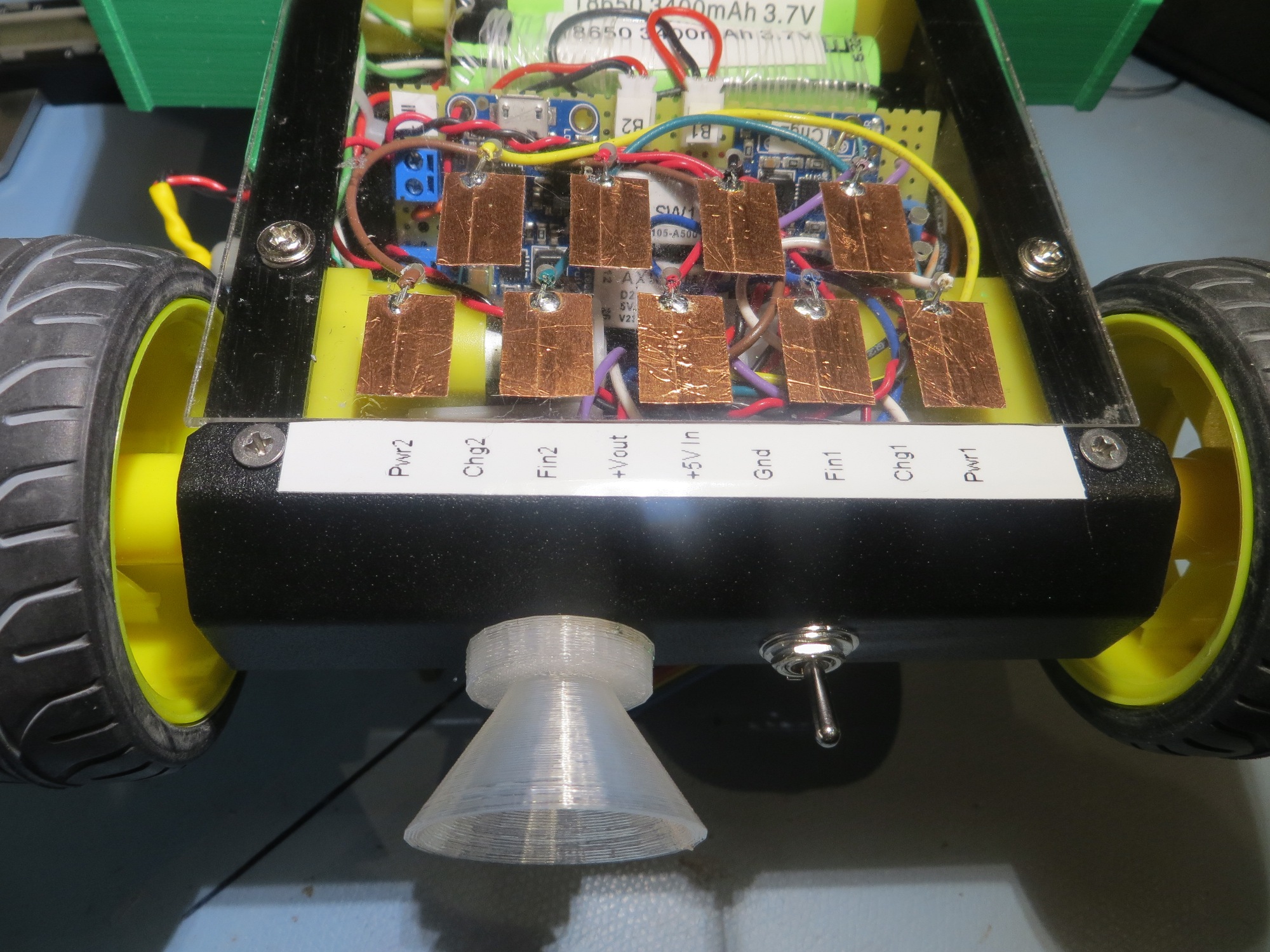
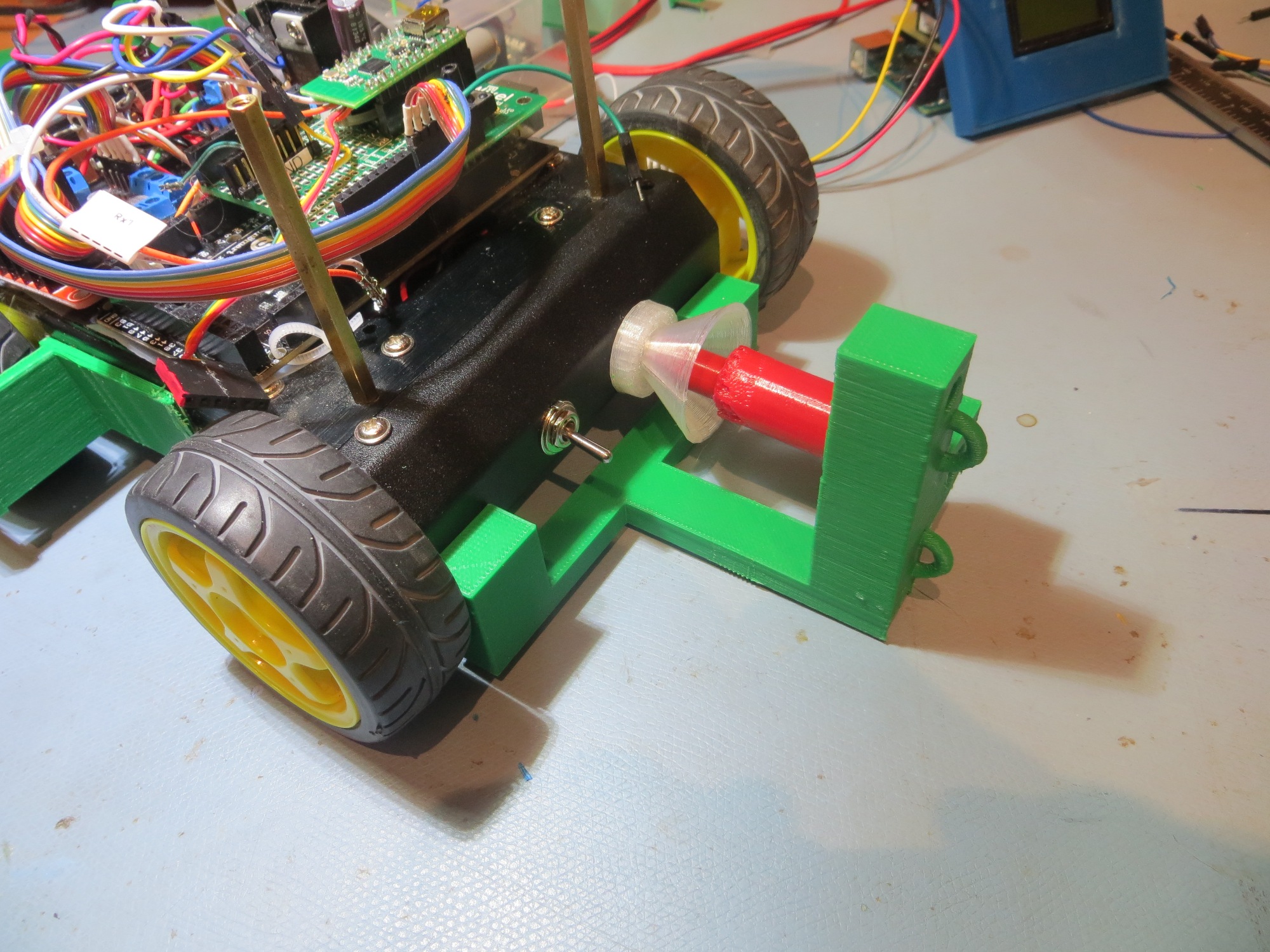
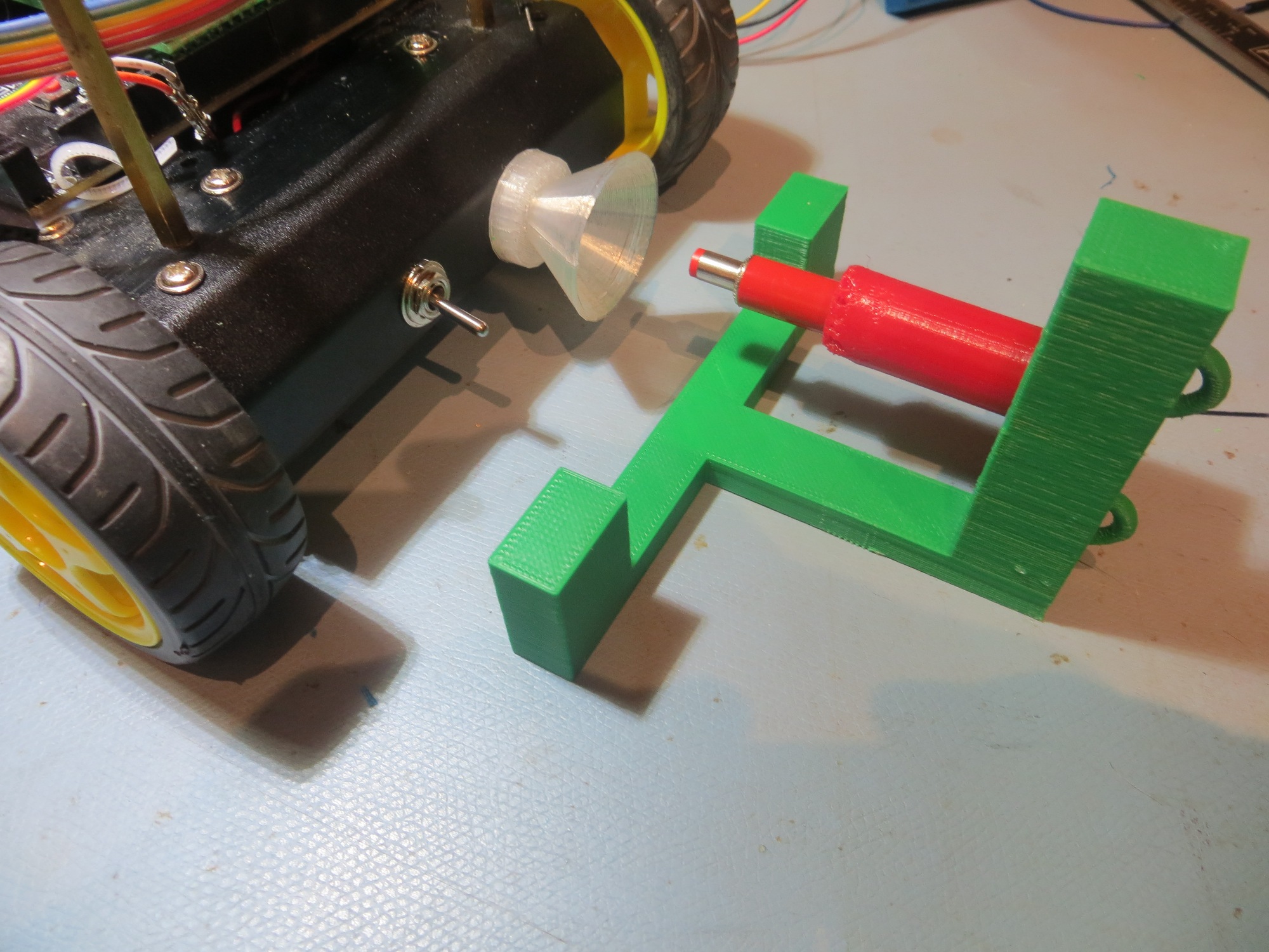
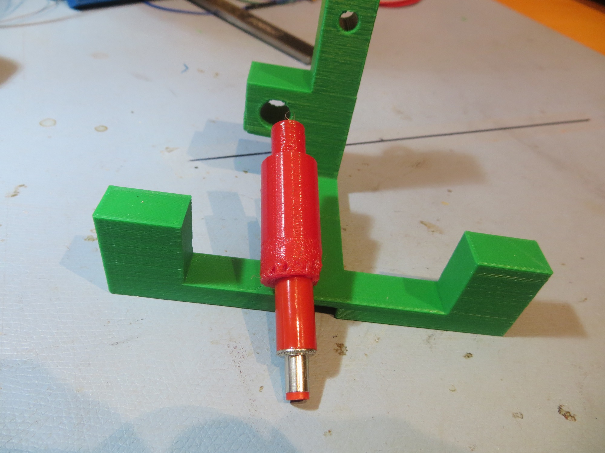
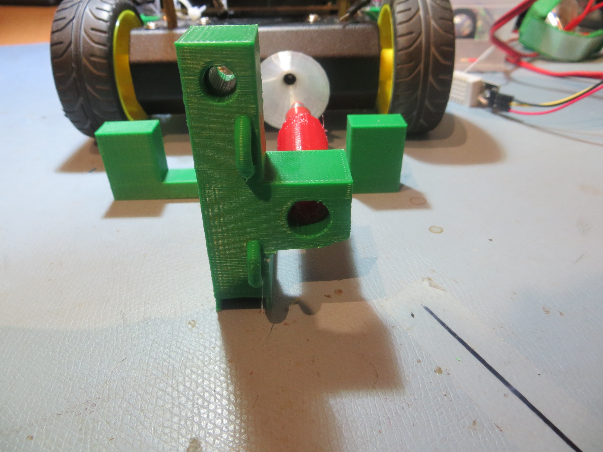
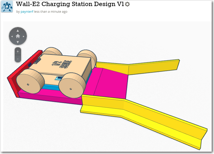
Independently of the above, I need to revisit the issue of how the charging station connects to the robot.  Originally, the idea was to connect via an array of contacts on the underside of the robot.  These contacts would mate with spring contact fingers on the top surface of a raised section of the fixed charging station, which would also contain status LEDs for the two embedded Li-Po chargers.  Unfortunately, I have been unable to come up with contact fingers appropriate for the application, despite trying three different contact finger ideas (EMI shielding finger stock, TE connectivity spring contact fingers, and Mill-Max spring-loaded contacts).  Fortunately, in the meantime I was able to successfully demonstrate  automatic external charging power connection using a guide funnel for the front-mounted external power jack and a semi-flexible probe tube with the mating external power plug mounted at its end.

The advantage of using the front-mounted jack for automatic power connection is that all I have to do is to get that one jack/plug pair engaged/disengaged, as opposed to the nine underside contacts.  This is a huge simplification of the problem, and one that I have already demonstrated to be feasible.  The major disadvantage of this option is that  all the charge-related decision making will have to be done by the robot, as the fixed part of the charging setup won’t know what is going on at all.  If I want to monitor charging status, I’ll have to do that via the onboard Arduino.  In the previous configuration (pre-MOSFET) this disadvantage was compounded by the fact that charging power could only be removed by physically disengaging the external power plug, which could only be done by some external physical mechanism since (by definition) the onboard wheel motors weren’t available during the charging process.  Since I now have a way around that dilemma (i.e. the robot can  now unilaterally switch from external to internal power by means of the MOSFET switch and then use the onboard motors to effect physical disengagement), this huge problem goes away entirely.  I still have the problem of how (or if) to display charging status, but this is trivial compared to the problem of physically disengaging the charging plug.

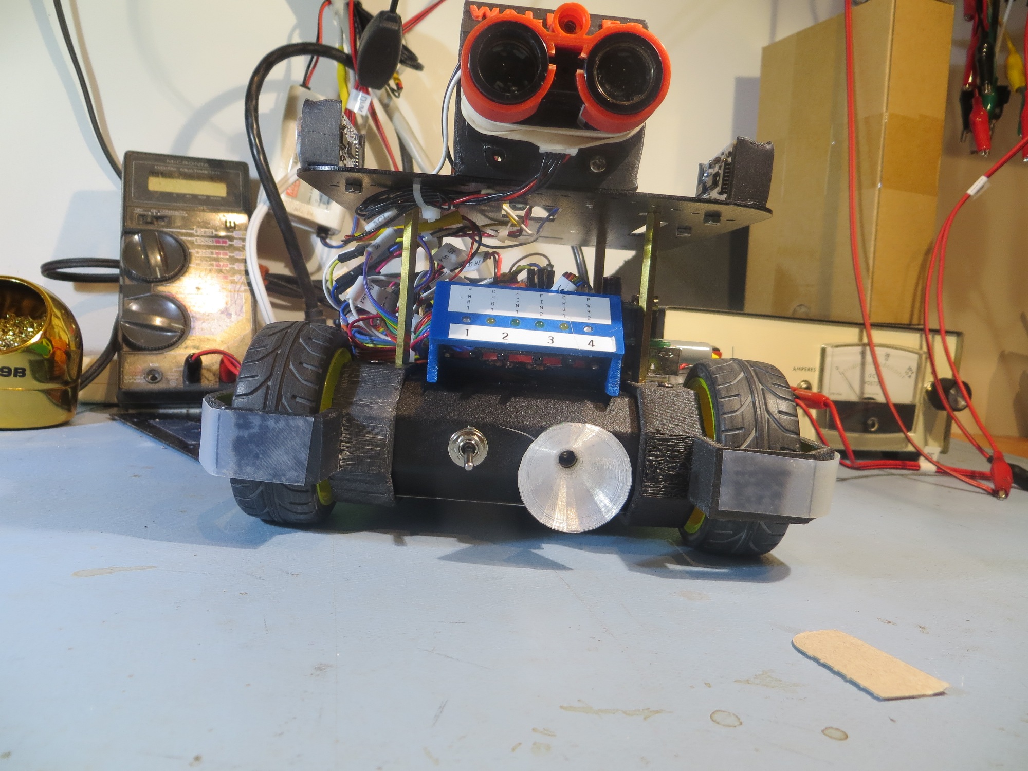
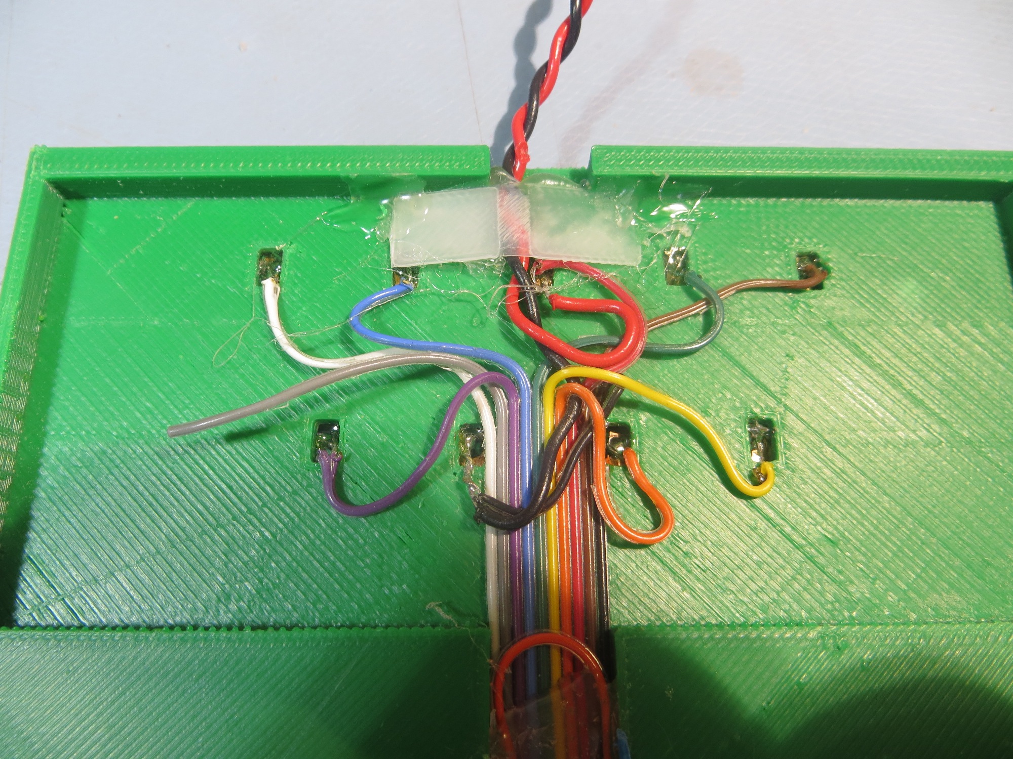
If I decide to abandon the underbelly contact array idea, then I can re-purpose the 8-pin header on the charging module to route charging status information to the Arduino instead of to the underbelly contact array. This header  is shown in the image below:

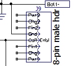
Charger module 8-pin male status/control header

As shown, there are 3 status pins for each cell charger, a ground line, and the new ‘Coil Enable’ line.  The status pins show whether or not the charger is receiving power (PWR), and whether the cell is still charging (CHG) or has finished (FIN).  In the original charging station design, the six status lines were brought out to individual LEDs via the contact array. If the underbelly array strategy is abandoned in favor of the single front-mounted connector, then these LEDs will have to be mounted somwhere/somehow on the robot itself.  Originally I was thinking that each status line would consume an Arduino Digital I/O pin, but now I’m not so sure.  All of these lines are actually already ‘powered’ from the charger modules themselves – all that is required to illuminate the CHG and FIN  LEDs is +5V – the status line is tied to an open-collector output through a limiting resistor.  The PWR status line is simply the +5V power to each cell charger, so a limiting resistor is required.  All the required signals and connections are available, so all that is needed is some sort of mounting arrangement on the robot – perhaps it could be integrated into the mounting for the front-mounted IR phototransistors in a manner similar to the ‘backup light’ mount at the rear?

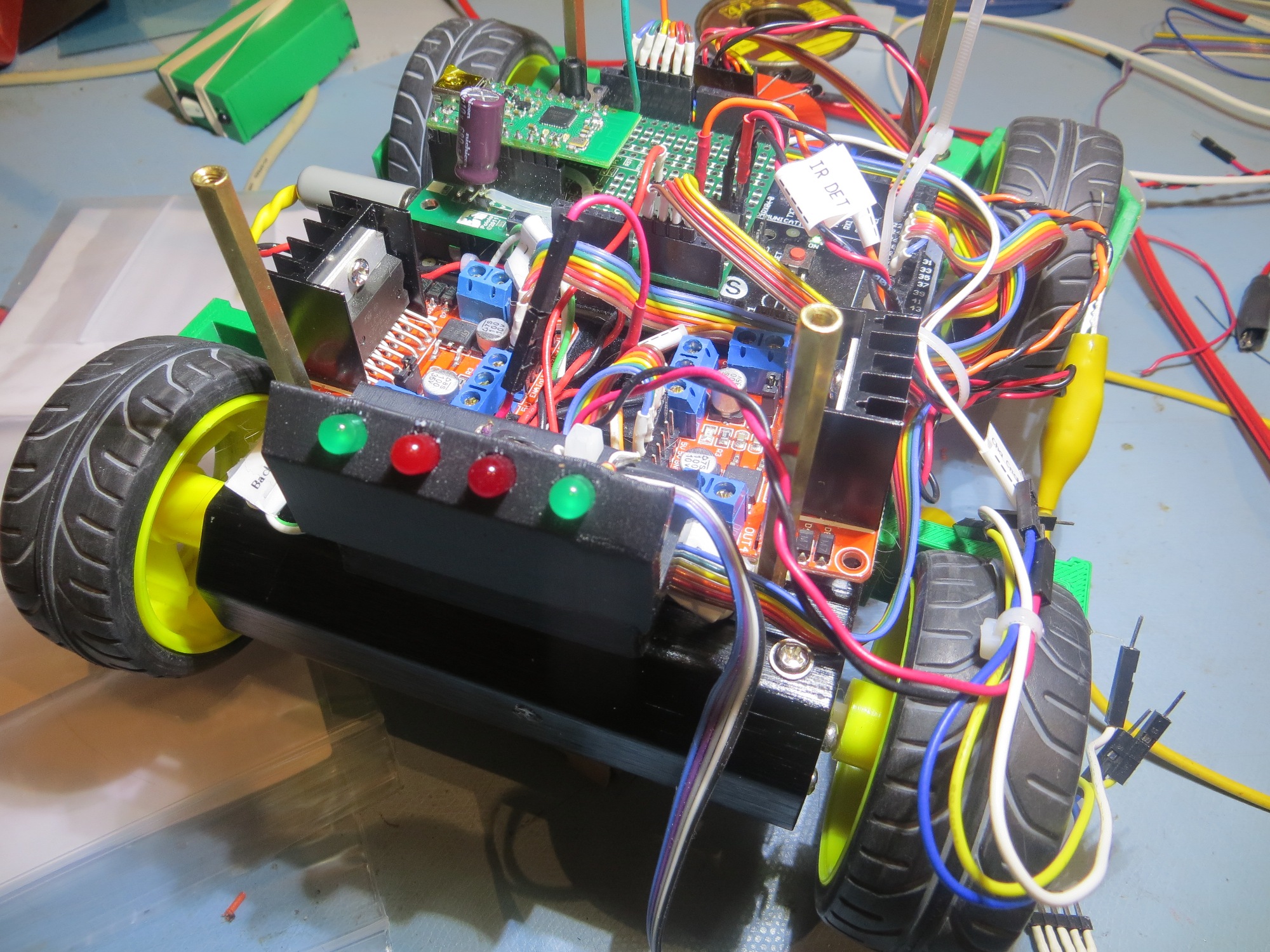
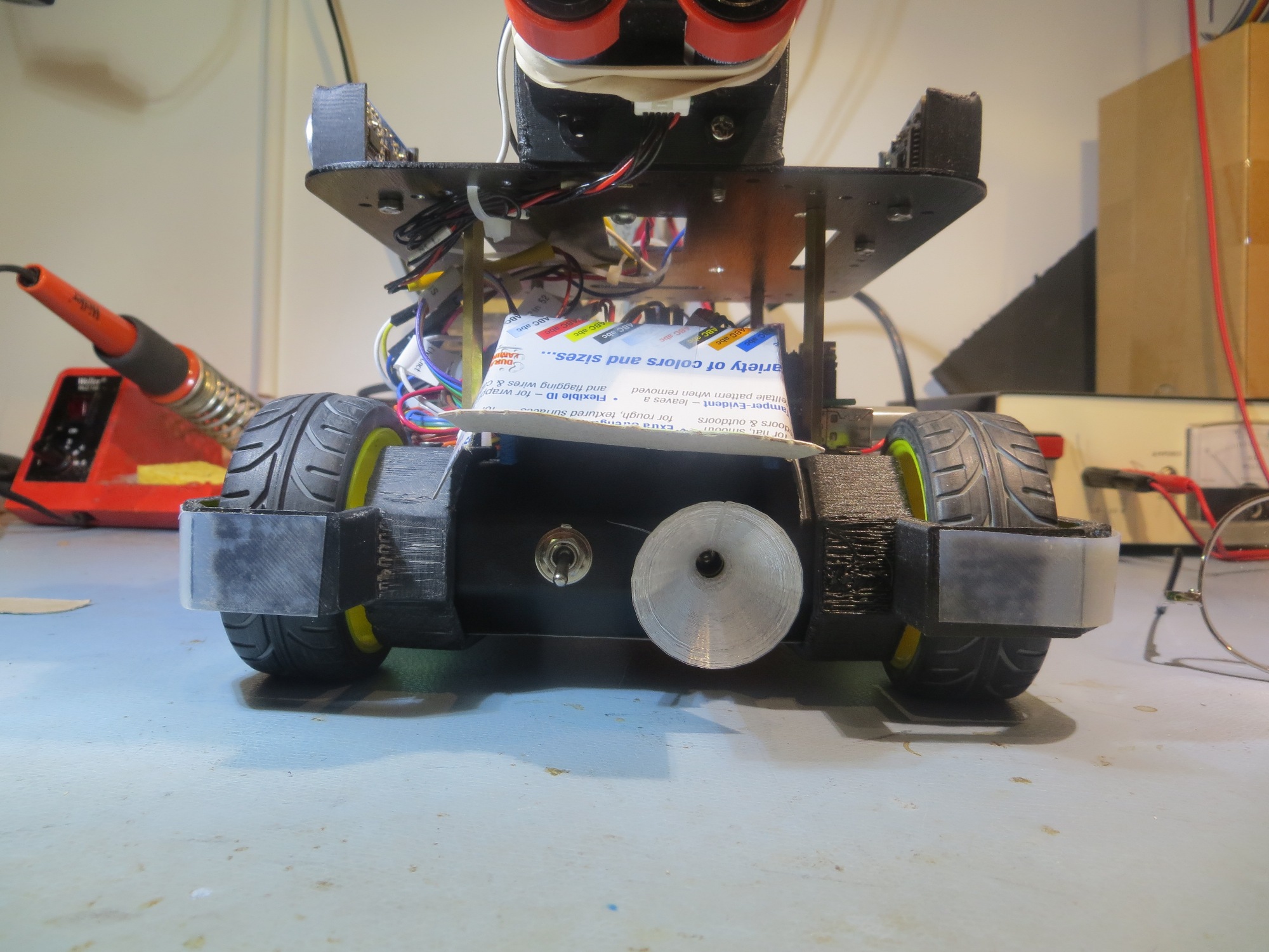
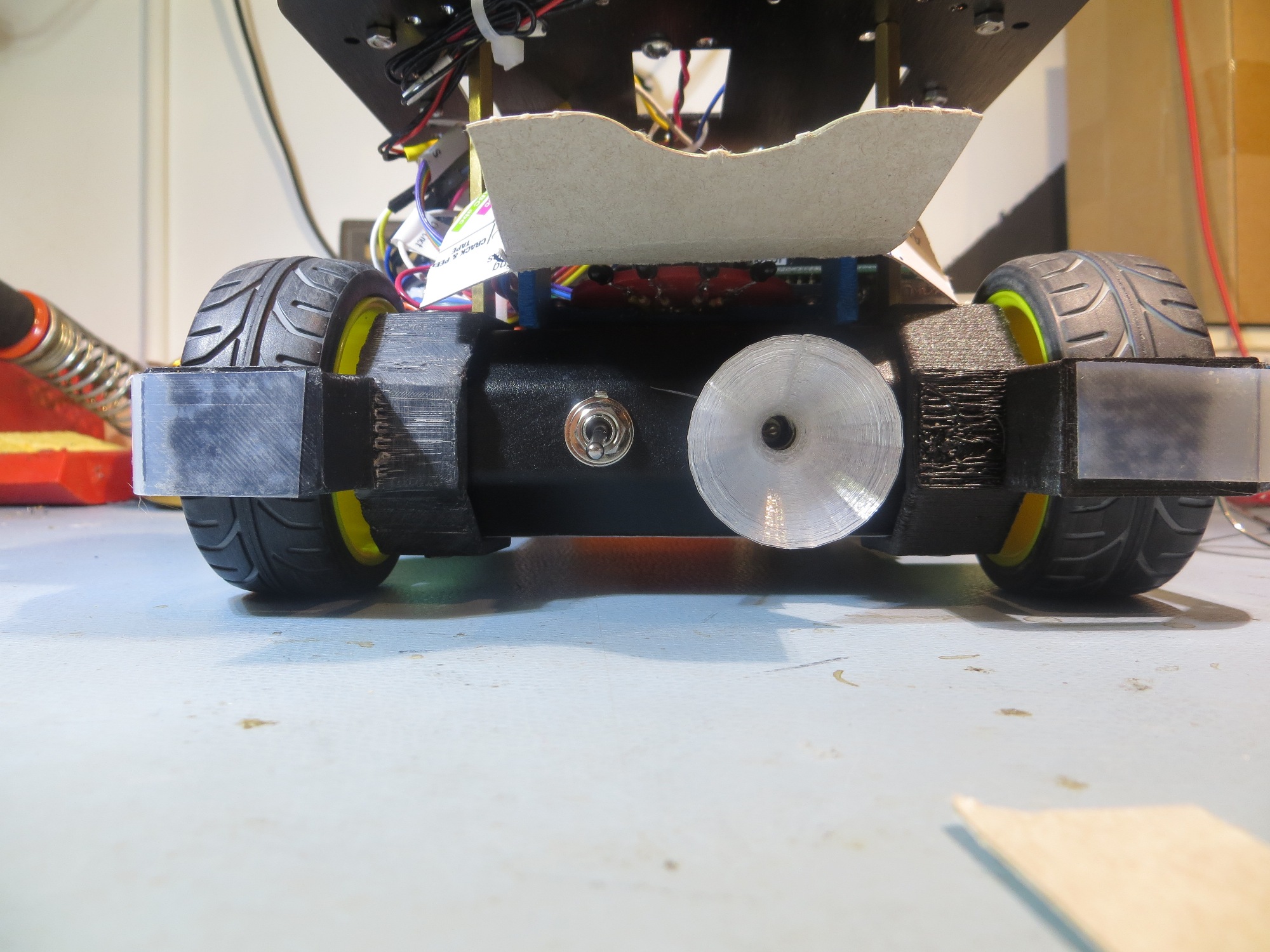
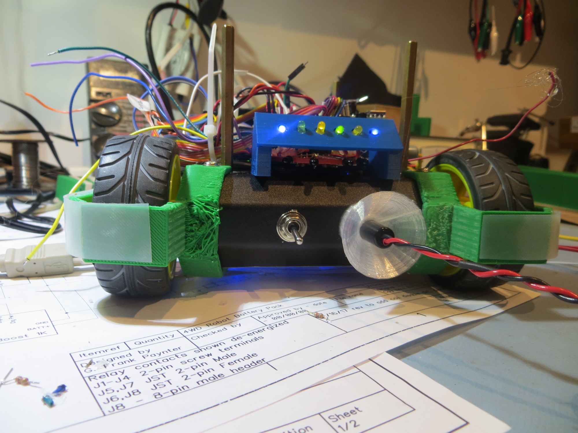
‘Backup Lights’ mounted to rear of the robot

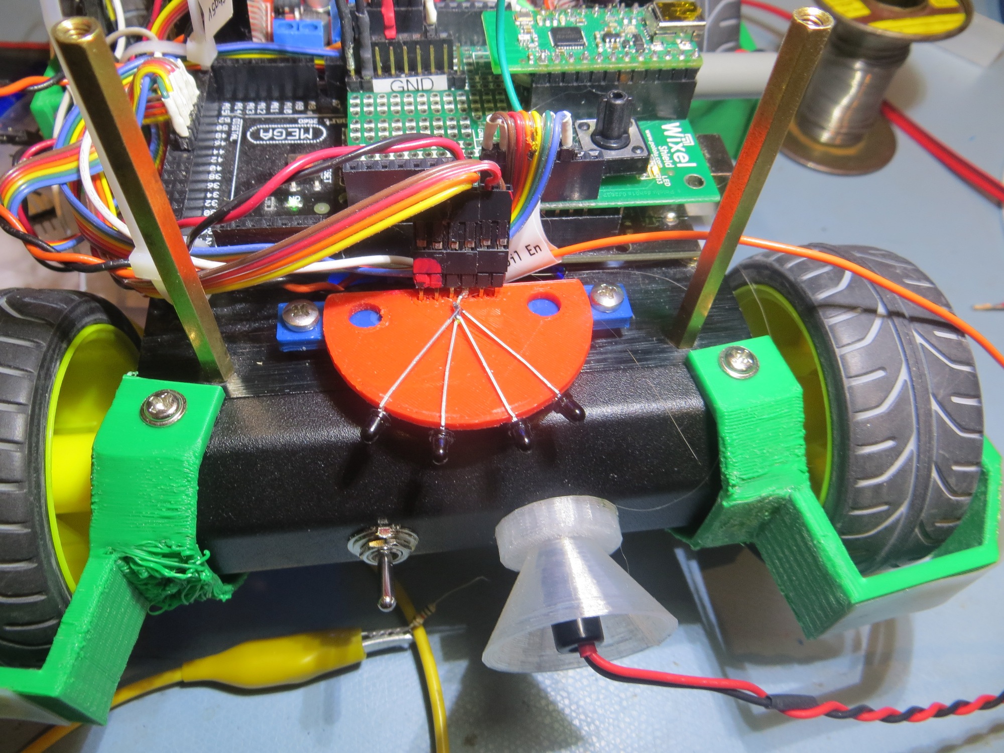
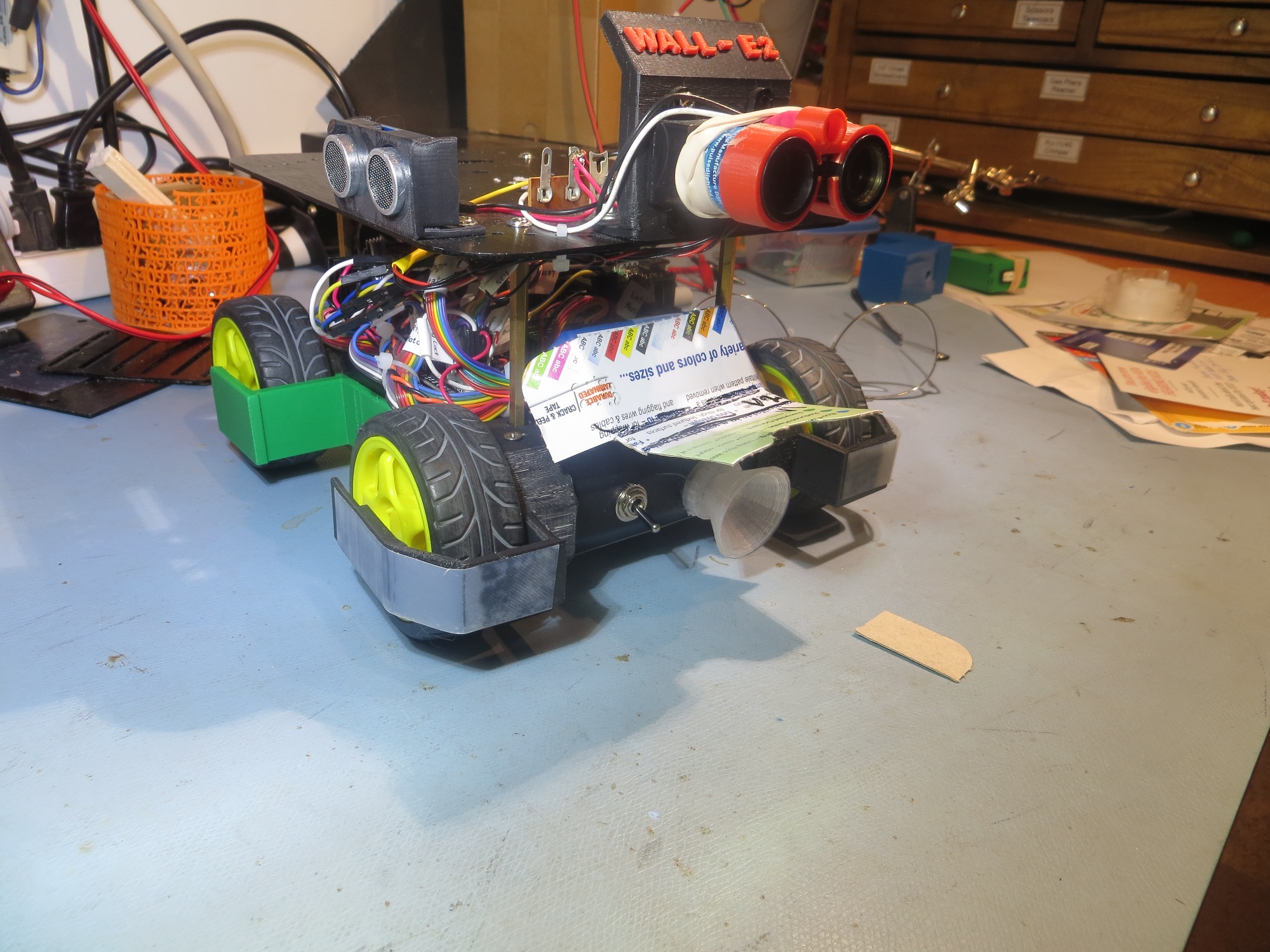
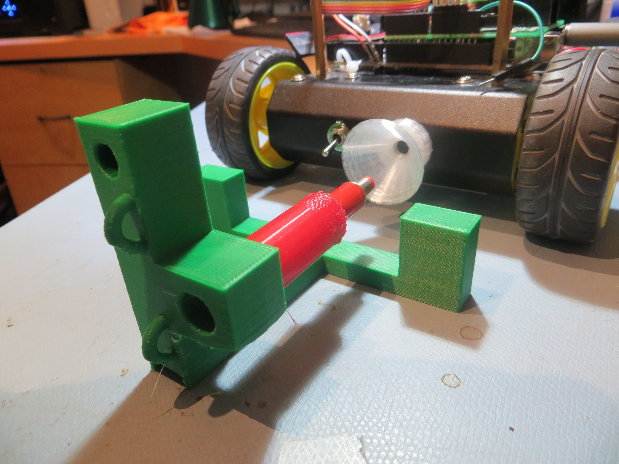
IR phototransistor mounting at the front of the robot

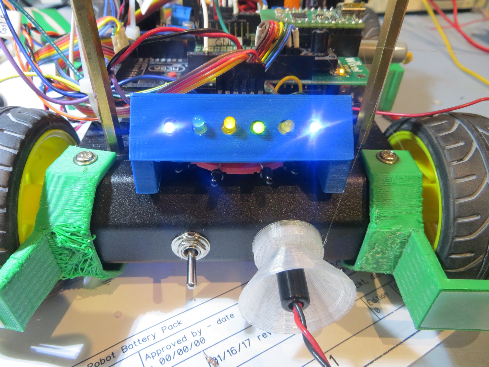
there would be more LEDs (7 vs 4) but each LED would be much smaller (3mm vs 5mm).  On the same 56mm panel, 7 LEDs could be spaced 6mm apart, with 6mm spacing on the ends, something like the following

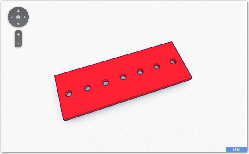
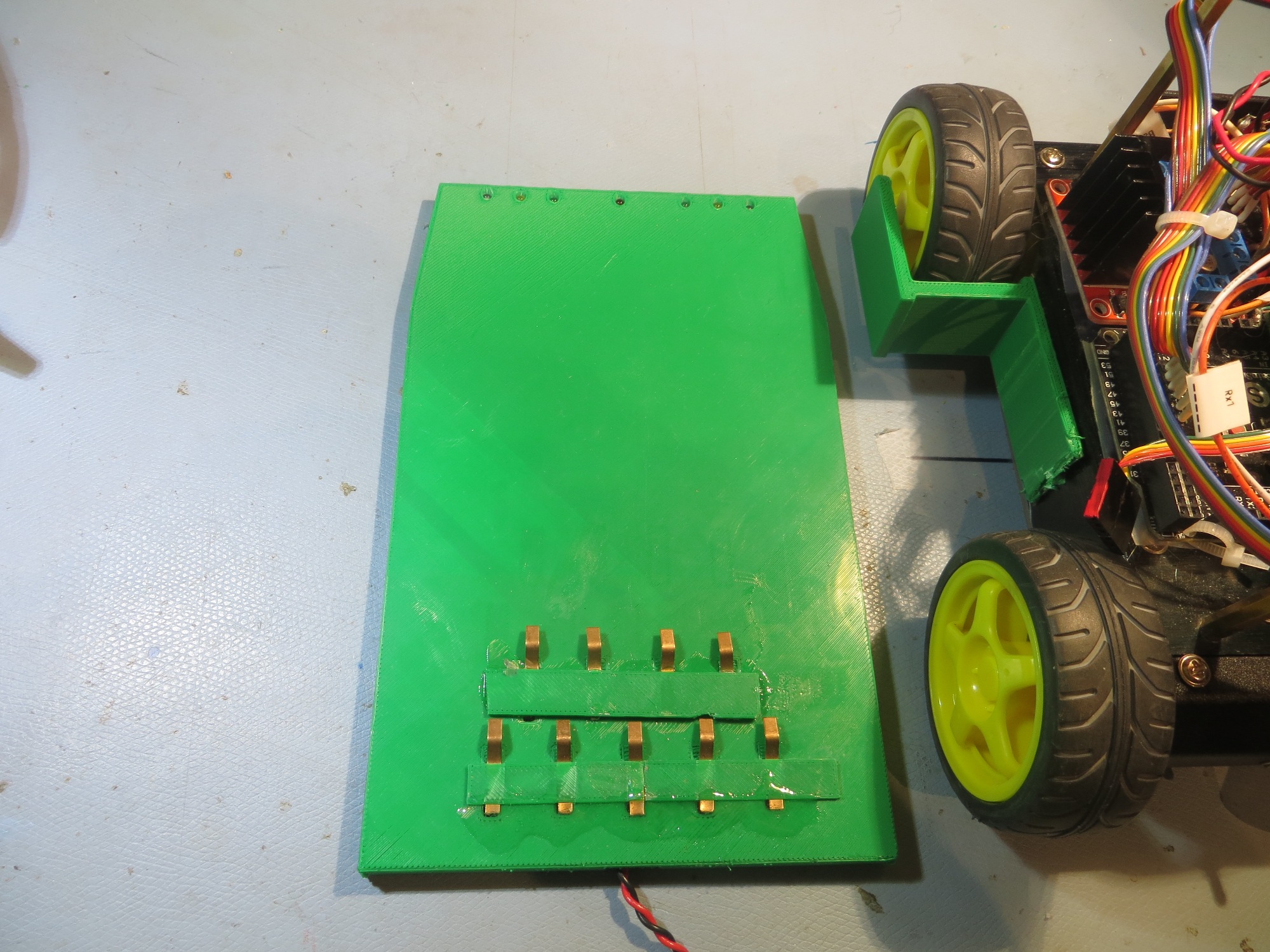
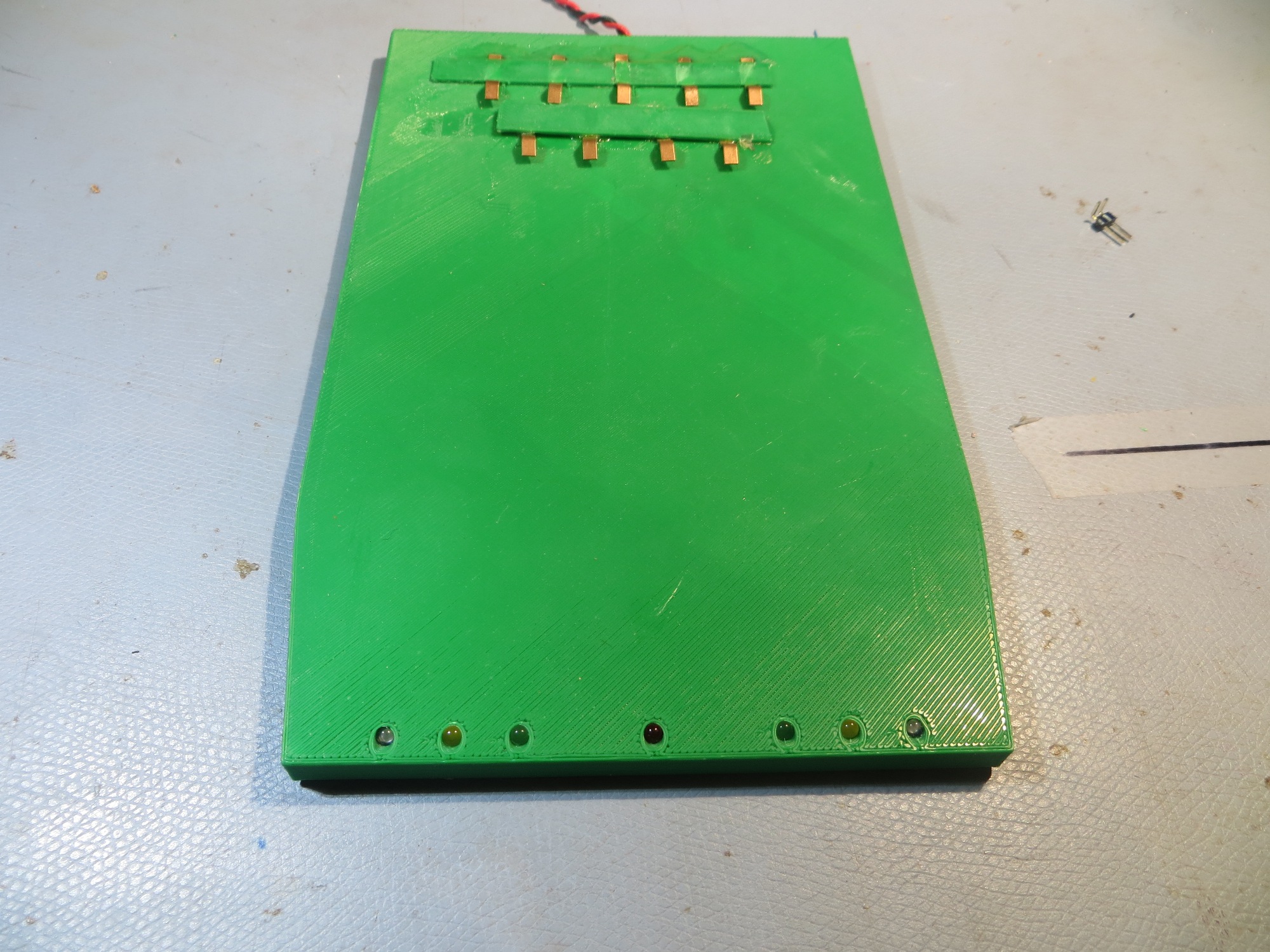
Prototype for a charging status LED panel

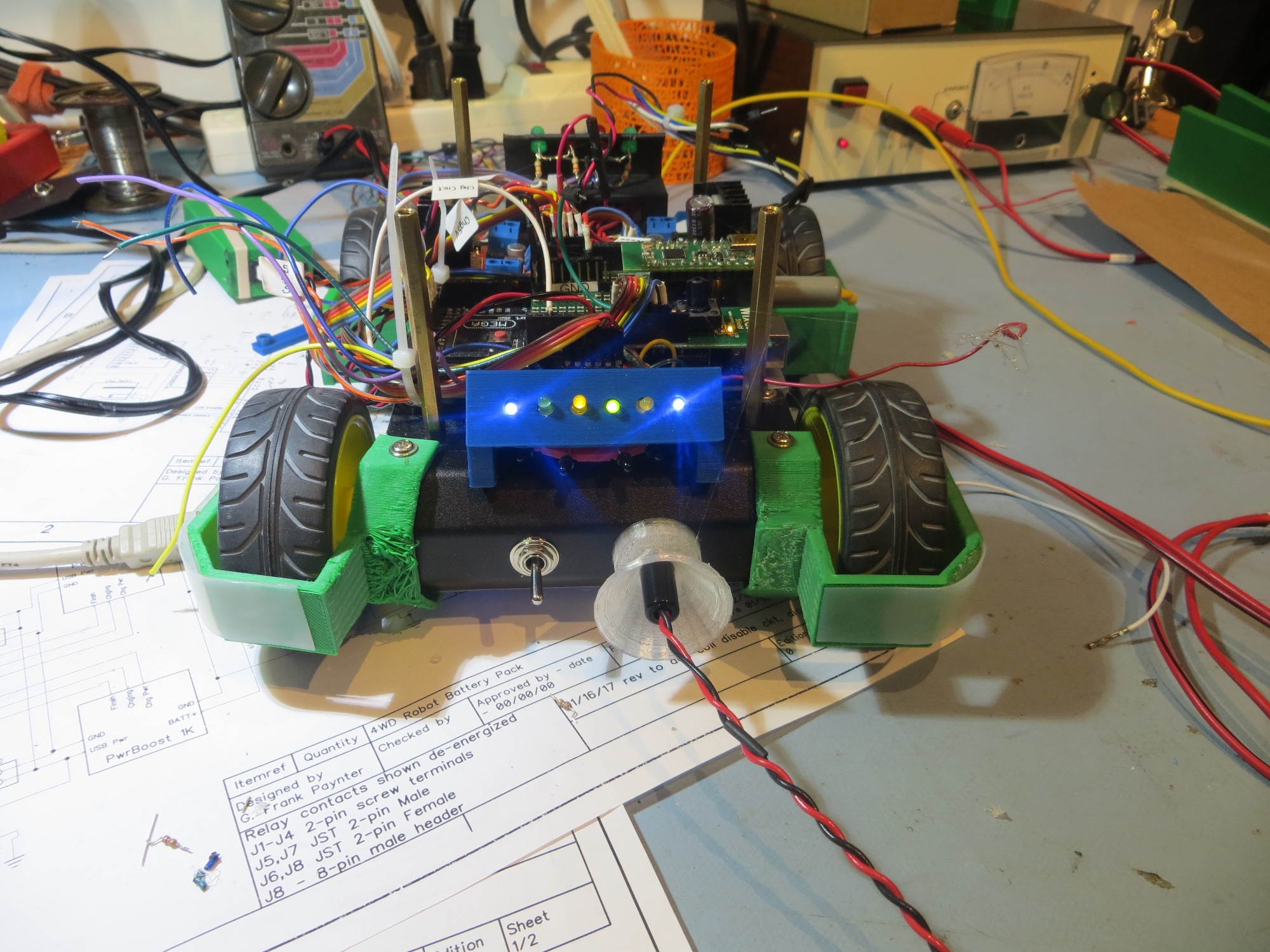
And, with my trusty PowerSpec PRO 3D printer I printed out  a full-scale feasibility assessment panel in just a few minutes, as shown below. Of course much more work would be required to make this into a fully functional panel, but just this piece shows that all 7 LEDs can be accommodated in a panel that is generally the same dimensions as the IR sensor module.

Charge status LED panel full-scale feasibility model

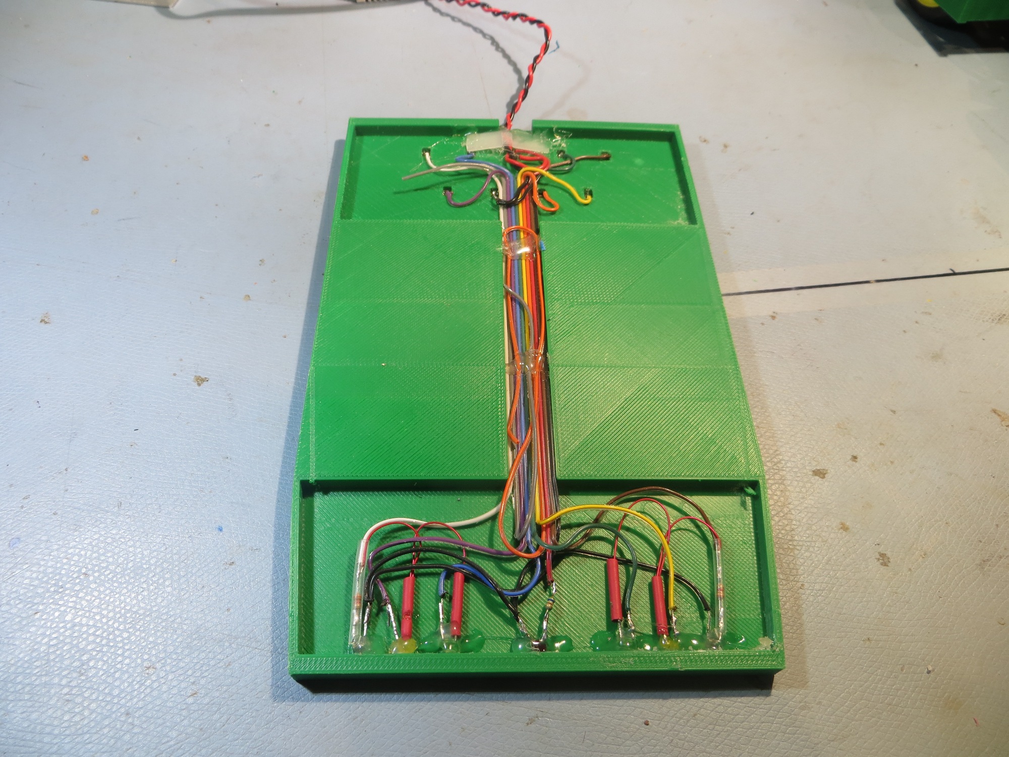
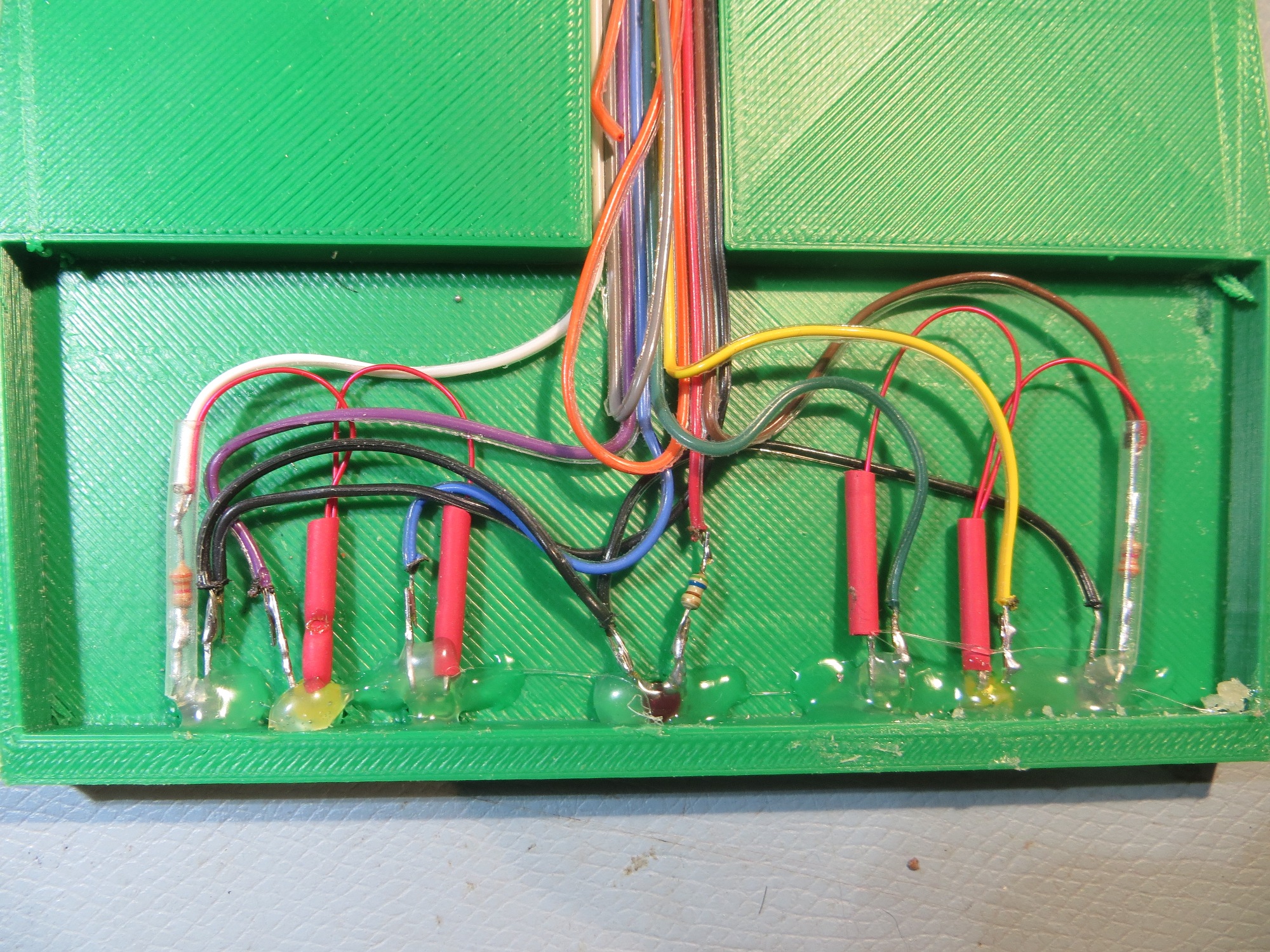
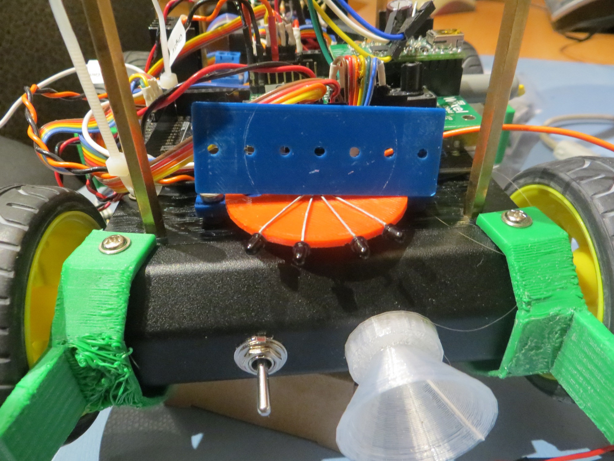
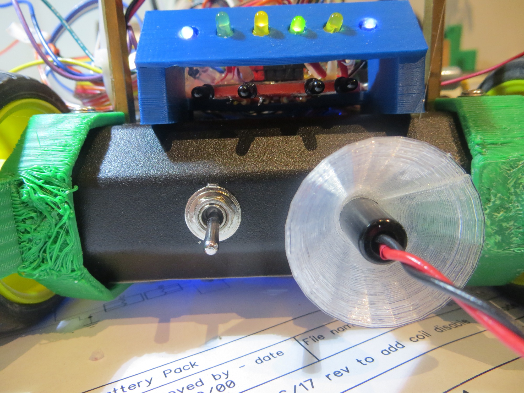
Charge Status Display Panel Update

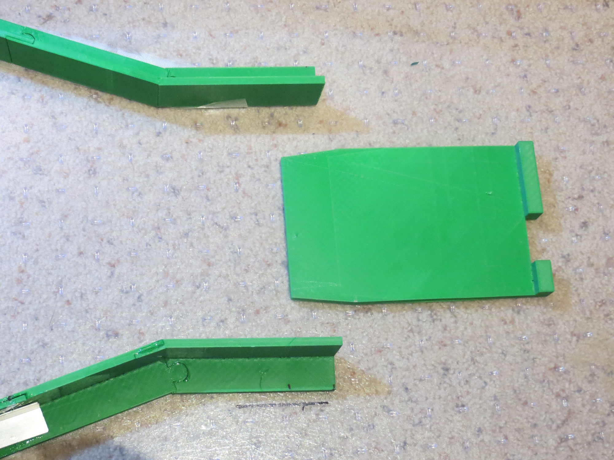
After the normal number of trials, I came up with a charge status display panel that could be co-mounted with the current IR detector assembly, as shown in the following images:

Stay tuned!

Frank


Wall-E2 Charging Station Design, Part VI

Posted 09 Jan 2017

It’s been a while since I have posted on my evil plan to set my wall-following robot free to roam the house terrorizing cats, all without the  need for charging assistance from mere humans ;-).  I have made a lot of progress  – but unfortunately not all of it has been positive :-(.

Charging Platform:

I was able to complete and print the final design for the fixed part of the charging platform, as shown in the following images

The idea was that the robot would be captured by the lead-in rails  and roll over the charging platform to a stop – thereby connecting to  the platform via the contact array.  The status LEDs would be visible to a person standing behind the robot.  Unfortunately, when I got everything all hooked up, the beryllium-copper finger-stock fingers proved too stiff to allow connection across the contact array; a couple of fingers were just a bit higher than the others, and the robot wound up suspended from these, and not making contact with the others – BUMMER!!

So, it was (literally and figuratively) back to the drawing board on the whole charging station idea – what to do?

TE Connectivity Flexible Contacts:

When I first thought of the idea of a charging station with flexible contacts and an under-robot contact array, I did a fair bit of web research on flexible contacts, and wound up with the idea of using individual fingers from a length of beryllium-copper finger stock, which is readily available on eBay.  Now that this option has been ruled out, it was back to the web again for more research.  This time I found a company called TE Connectivity, and they have a line of flexible contacts for use in connecting PCBs to cases in mobile devices, among other things, as shown in the following images.  They have a  huge variety of contacts, so I was able to find four good possibilities with uncompressed heights between 3 and 4mm.  Even better, The TE connectivity folks let me order samples – yay!!


I practically wet my pants when I found these, as I think they are the answer to my prayers; otherwise I would probably have to abandon the entire charging platform/contact array idea.

Automatic 5V Charging Connector Mating Option

When I installed the new battery pack in Wall-E2, I also re-installed the  5V power jack that came with the original kit.  I figured that I could use this jack to manually charge the batteries until I got the human-free option working.  While waiting for the connector fingers from TE to arrive, I started thinking that I just might be able to work up a way to have Wall-E automatically drive itself onto the mating 5V plug to charge, then back off of it when finished.  I had not pursued this in the past, as I thought it would be too hard to get the plug and jack lined up with any consistency, but now I was reconsidering it as possibly the only remaining option.  And, since I have a 3D printer sitting on my workbench, I started experimenting with coupling ideas.  The first challenge was to design and fabricate a ‘capture basket for the 5V jack, so that the initial alignment wouldn’t have to be perfect.  After the normal half-dozen or so failed designs (have I mentioned how much I love the ability to do short turn-around design/fabrication cycles?), I had a design that I thought would work, as shown in the following photos.

The ‘capture basket’ fits very snugly over the 5V power jack, and is designed such that the slanted sidewalls mate up seamlessly with the lip of the jack – no flat spots or corners to impede the plug on its way in.  I was a little bit worried about the granularity inherent in FDM prints, but this turned out to be a non-issue, as shown below.

After getting the capture basket designed and fabricated, it was time to work on the other end – the plug probe. I already had a tentative design for a part that would serve as a stop for the robot while also providing a mount for the IR beacon LED, so I decided to add the plug/probe to this fixture, as shown below

I was able to simply add a block of plastic onto the side of the original stop/IR LED holder to accommodate the plug/probe assembly. The probe was fabricated from NinjaFlex to allow for some flexibility as the plug mates with the jack.  As the following video clip shows, this arrangement seems to work quite well!


So, now I have what appears to be a viable alternative to the contact-finger/contact array strategy.  The jack/plug alternative has a  significant drawback  in that I can’t bring the battery charging status signals out for off-robot display.  If necessary that can be accommodated by constructing some sort of on-robot status LED strip (not sure where I would put it, but…), but it would certainly fulfill the primary requirement of allowing the robot to feed itself, and there’s no real need to keep those puny humans informed, anyway ;-).

Stay tuned!

Frank


Wall-E2 Charging Station Design, Part IV

Posted 10 December 2016

Well, two important steps occurred today in my plan to take over the world (well, maybe just make Wall-E2 more human-independent). The first was the arrival of my Panasonic 18650 batteries, and the second was the successful trial of my first stab at a charging platform.

The ‘platform’ part of the charging system (the blue piece in the image below) is the part that captures and positions the robot accurately enough to connect to charging power, via contact strips on the bottom of the robot and spring-loaded contacts on the platform.

1/2-scale concept model for the Wall-E2 charging station.  The blue part is the ‘charging platform’

So today I printed out a full-scale platform.  This was pretty amazing by itself, as it took up nearly the entire build area, and took about 4 hours to print.  Fortunately I had recently upgraded my build platform with a PEI surface and also re-leveled it, so the printer was up to the task. It did take me a while to get the darned thing OFF the build surface, as it was  very well adhered to the base 😉

Robot’s eye view of the charging platform

Overall view of the lead-in rails and the charging platform

Closeup of the charging platform piece. Note the beveled section at the entry end

To test the combination of the lead-in rails and the charging platform, I double-sided taped  the platform in what I hoped was the best position/orientation, and ran some more tests with the robot, as shown in the following video clip.

This last series of tests, in conjunction with my earlier work on IR following,  was quite rewarding for me, as I now had incontrovertible proof that the lead-in rail/charging platform idea would really work.  It might not be ‘optimum’, but I was now sure I could get the robot to track an IR beam accurately enough to get captured by the lead-in rails, and the platform would position the robot accurately enough to make the charging connections – yay!!!

Now I have to start serious work on the other end – the actual charging and battery circuitry.  With the arrival of my Panasonic 18650 cells, I now have all the required parts – I just have to put them all together, make it all work, and somehow shoehorn the entire mess into the robot!

Stay tuned,

Frank


Wall-E2 Charging Station Design, Part III

Posted 12/05/16

I’ve been making some progress with the planned charging station lead-in rails.  These rails (shown in yellow in the image below) are intended to guide the robot into the charging station,  lining it up  properly  with the charging station so the contacts on the bottom of the robot will properly mate with the corresponding contacts on the top of the charging station platform.

1/2-scale robot chassis on the 1/2-scale charging station model

1/2-scale robot chassis on the 1/2-scale charging station model

These rails are too big to print in one piece on my PowerSpec PRO 3D printer, so I had to devise a way to print them in sections, which could then be plugged together to form the complete rail.  To do this, I designed a  coupling geometry consisting of a ‘puzzle-piece’ connector and a slide-fit arrangement, as shown below:

Lead-in rail angle coupling design

Lead-in rail angle coupling design

Lead-in rail straight coupling design

Lead-in rail straight coupling design

After going through several iterations ‘on paper’, I printed out a 1/2 scale model to verify that I could indeed connect the pieces to make a whole lead-in rail, as shown below:

Half-size capture basket rail

Half-size capture basket rail

Half- and Full-size capture basket rails

Half- and Full-size capture basket rails

Full-size capture basket rails

Full-size capture basket rails

Now that I had the capture rails fabricated, it was time to find out whether or not the capture system would actually work.  I used double-sided tape to affix the two rails to one section of the heavy plastic desk-chair runner system in my lab/office, at the proper spacing to just pass the robot, assuming it was properly aligned with the capture gap, and then ran some tests, as shown in the attached video clip.

In the video clip, the first two trials were conducted with the ‘stock’ wheel guards with right-angle corners, and the remaining ones were conducted after filing a small bevel into the front corners to (hopefully) alleviate the sticking problem


Front wheel guard with filed bevel on outboard corner

After seeing that the filed bevel seemed to improve performance, I decided I would go ahead and redo the wheel guards to provide a more pronounced bevel.  Thanks to TinkerCad and my trusty 3D printer, this was a piece of cake.

Redesigned wheelguard to incorporate bevel on outboard corner

After changing out the wheel guards, I ran some more tests with my taped-down capture basket,  but soon discovered yet another ‘capture failure mode’, as shown in the following image.

Robot stuck in capture basket

As you can see in the image, the rear part of the front wheel guard and the front part of the opposite wheel guard is just the right shape and spacing to form a stable lockup configuration.  To address this little problem, I decided to remove the rear portion of the front wheel guard on each side, but left the two rear wheel guards intact.  Then I ran some more capture basket tests, with very encouraging results.


So, at this point I’m pretty happy with the capture basket lead-in rail design (3 failures in 14 tries), and with the robot wheel guards.  Next, I’ll need to fabricate a full-scale charging platform for the robot to stop on, and also work on the new charging/battery setup in the robot itself.  Stay tuned!

Frank


IR Light Follower for Wall-E2, Part X. More PID Tuning

Posted 19 November 2016

Well, as usual, things aren’t quite as simple as they seem, and the ’10 minutes, tops’ rule still applies (whenever someone says ’10 minutes, tops’, they are lying by  at least one order of magnitude!).  But, on the bright side, I really do understand PID control systems a lot better now (a low bar, as just the other day couldn’t remember what the ‘P’ in ‘PID’ stood for!), and I now think that WallE (and/or WallE2) has  a pretty reasonable chance of homing in on an IR beacon with sufficient accuracy to be captured by a charging station setup.

In my last post on PID tuning, I had assumed that the PID compute engine normalized the tuning constants before doing the computation, and I decided I needed to check that assumption before continuing.  When I looked into the actual code in the Arduino PID library, I found that this was  not true – the PID compute engine does not normalize.  It simply computes the PID expression:

output = kp * error + ITerm- kd * dInput;

where ITerm is  ITerm+= (ki * error)

However, what this means is that my previous attempts to simplify the tuning problem by eliminating the I and D terms and just tuning the P term was doomed to failure – there was no way ‘do just P’ because the physical dynamics are too complex.  The response curves of the IR detectors (shown below),

4-detector heading test results

4-detector heading test results

combined with the physical dynamics of the robot itself, require more than just a proportional response to the error (the difference between the sums of the two left and two right detector readings)   term.  Ken suggested I could do this by using a pulse train (similar to PWM) for the motor drive signal, but I think that is equivalent to adding some ‘D’ to the PID tuning parameters.

In addition to the physical dynamics issues, there is also the problem of the detector response versus distance.  At maximum detection range, all detector readings are near 1000, so the error term is very small, on the order of 10-50.  However, as the robot gets closer to the emitter, that error term rapidly gets much larger, on the order of 500-900.  This means that the PID tuning parameters appropriate for the ‘far’ case will be wildly inappropriate for the near case (another consequence of not normalizing the PID values internally).

In any case, after a  loonnnggggg series of floor field tests, I think I have arrived at a reasonably effective homing algorithm.  Instead of trying to modify the PID tuning parameters as the robot approaches the emitter, I found it more effective to keep the PID tuning parameters constant, and instead scale the  PID input (error) signal in three steps; 1 (no scaling) for error term values below 200, 0.2 (divide by 5) for values between 200 & 500, and 0.1 (divide by 10) for values above 500.  A representative set of data and some videos are shown below.  The last video shows a ‘side capture’ scenario, where the robot approaches at right angles to the IR beam and successfully captures the beam and homes in on the emitter.

Typical run with 1/5/10x scaling as emitter is approaced

Typical run with 1/5/10x scaling as emitter is approached.  Scaling term is shown here at 100x for clarity

Side capture scenario. Scaling term is shown 100x for clarity

Side capture scenario. Scaling term is shown 100x for clarity


So, at this point I’m convinced that the PID/input scaling arrangement will work, and that I can get WallE2 to home in on an IR beacon.  The next challenge will be to integrate the IR homing function with the normal wall-following function, and to design/fabricate the charging station itself.  Stay tuned! ;-).

Frank


IR Light Follower for Wall-E2, Part IX – PID Tuning

Posted 16 November 2016

In my last post on this subject, I described by attempt to add PID control functionality to WallE’s IR light-following algorithm, and this is now looking pretty promising.  As an added bonus, I managed to suck my stepson Ken Frank, who graduated from Cornell with a MS in control theory, into helping me tune the PID controller. His first comment (well, the first comment after the obligatory “what have you gotten me into now, Ollie!”) was something like “you are over-controlling – you should simplify the problem and start with just ‘P’ – no ‘I’ or ‘D’. Then add P/I as necessary after getting the P value right.  Wish I had thought of that! ;-).

Anyway, I revised the code to do just that – with PID tuning parameters of 4,0,0 for both the far away and near cases, and re-ran my ‘floor range’ field test, as shown in the following video clip and plots.

Left/Right Differential (input to PID engine) and Output

Left/Right Differential (input to PID engine) and Output

All data from the run

All data from the run

More to follow…


After taking the above video and data, it occurred to me that it was possible (although not very probable, IMHO), that the PID engine might not normalize the tuning parameters before computing the new output.  So, I ran two more tests – one with a PID of 1,0,0, and another with a PID of 10,0,0.  These tests, along with the ones for 4,0,0, should provide some insight into that question.  As can be seen from the plots, the tracking behavior for all three PID = X,0,0 conditions are pretty similar.  I also included a video clip of the PID = 1,0,0 condition.


161116_floorfieldtest15data 161116_floorfieldtest16data


More to follow

Frank