Tag Archives: MPU6050

MPU6050 FIFO Buffer Management Study

Posted 13 October 2019

I have been attempting to use the Invensense MPU6050 6-axis IMU for some time now in both my two and four-wheel robots for improved wall-following ability. By measuring the relative heading change during turns, I could get the robot to accurately acquire and maintain a specified distance from the currently tracked wall.  I say ‘attempting’, as I have experienced somewhat mixed results in getting reliable results from the IMU.  A large part of the problem, as I described in this post, wasn’t the IMU at all, but rather the sensitivity of the Arduino I2C bus to RFI/EMI caused by the motor drivers.  However, even after solving this problem, my programs would still occasionally ‘lose synch’ with the IMU’s FIFO buffer and start returning garbage for heading values – not good!

In addition to the I2C issue, there are several factors that make the MPU6050 harder do work with:

  • Invensense, the company that makes the MPU6050 chip, appears to have been purchased by TDK, and their technical support forums don’t appear to be supported any longer.
  • Apparently there are significant pieces of the MPU6050 firmware that aren’t freely available as human-readable code, so much of the MPU6050 magic is just that – magic.  In particular, the details of how the MPU6050 handles its internal FIFO are (at least to me) completely unknown, except by reverse-engineering.
  • While there is a lot of MPU6050-related information and code floating around out there in the i-verse, that is as much a trial as a blessing; it has been very difficult for me to wade through everything and to try to sort out the wheat from the chaff.
  • Jeff Rowberg’s wonderful I2CDevLib contains support for the MPU6050, with examples.  While it is fairly easy to get started using Jeff’s examples, it was difficult for me to understand how the examples work so I would know how to modify them for my application without running off into the bushes.
  • Almost all the example code out there assumes an interrupt based IMU management scheme.  For my wall-following robot application, the interrupt scheme was overkill and then some, so I wanted to use a polling arrangement, which is very poorly documented. Eventually I developed a working polling algorithm (described here) , which I now use in my robots.
  • Invensense (now TDK) has released several updates to the MPU6050 firmware, and it is difficult (at least for me) to figure out what the differences are and whether or not those differences are worthwhile for my application.  There is some information in the header files provided by Jeff Rowberg, but if there is any sort of formal change history, I haven’t found it.

Despite all this, the MPU6050 is a wonderful device, and it’s EVERYWHERE – you can get MPU6050 modules from Adafruit, Sparkfun, DFRobots, and GY-521 Chinese knockoffs from eBay.  The GY-521 modules have some reputed issues with quality control, but at about $1-2 per module, it’s hard to go wrong.

In my continued attempts to understand how the MPU6050 works, and the details of some of the latest example code provided on Jeff Rowberg’s Github site, I posted an issue related to a particular part of the example code that defied my ability to understand, as shown below:

This code obviously works, but I get a headache everytime I try to figure out how it makes sense.  One of the replies I got from this post was from Homer Creutz, who I knew to be one of the very best experts on all things MPU6050.  The gist of Homer’s reply was “yeah, it looks kinda clumsy, but it does work”. But then Homer went on to suggest an alternative using the modulus (%) operator that piqued my interest, as I had used this technique in my four-wheel robot code.  In subsequent email conversations Homer went WAY out of his way to thoroughly answer my stupid questions about the MPU6050, especially about the issue with FIFO overflow.  He sent me a link to this video explaining how circular buffers work, and the following graphic illustration (slightly edited for clarity) of the problem of MPU6050 overflow and multiple-byte packets

The combination of the video and the above simple graphic finally allowed me to understand why properly managing FIFO overflow is so critical for successful MPU6050 implementations. Ironically, FIFO overflow management is more of an issue in my low-speed, high mass, low-dynamics environment than at the other end of the scale.  In high-dynamics applications, FIFO overflow is almost never an issue because the application sucks data out of the FIFO as fast as it is put in, in order to provide the best possible stabilization and control.  However, in low-dynamics applications like my wall-following robots, there is no need for IMU information more than a few times per second, meaning that the FIFO will almost certainly overflow if it isn’t proactively drained even if the information isn’t really needed.

Homer also sent me a couple of untested alternatives for FIFO management to replace the ‘while() within an if()’ algorithm, so I decided to test them and report the results back to Homer. After all, Homer was going WAY out of his way to answer my ignorant questions, so the least I could do was to be his lab tech.  So, I started with Jeff Rowberg’s MPU6050_DMP6_using_DMP_V6.12 example (the one with the ‘while() within an if()’ snippet) and modified it to deliberately cause FIFO overflows. After a bit of debugging and some very slight changes to Homer’s code, I got the following output from a run using a 100 mSec delay at the start of loop():

As can be seen from the above, about 20 interrupt cycles are skipped in each loop() iteration, causing the 1024-byte FIFO contents to expand by either 280 or 252 bytes each time, until it overflowed and was reset.  The example code handled FIFO overflows properly resetting the FIFO each time so that the retrieved yaw values continued to make sense.

The next step was to replace the example code with Homer’s proposed setup using the modulus operator for FIFO management. The first section below shows the example code loop() function before Homer’s modifications:

And the following shows the same loop() function after implementing Homer’s suggested code:

This resulted in the following output:

Showing that FIFO overflow was indeed handled properly.  The FIFO overflowed after the 3rd time through the loop, (the returned count was capped at the 1024-byte physical length of the FIFO), and Homer’s code correctly removed the 16 corrupted bytes at the beginning of the FIFO, plus one more 28-byte packet.  The subsequent mpu.getFIFOBytes() call retrieved an entire valid packet, which was then process to produce a valid yaw value.  Of course, since only one extra packet was removed, the FIFO overflowed again when the next 336 bytes were loaded during the 100 mSec delay at the start of the next loop() iteration.

When the code snippet to retrieve all available packets

was uncommented from the above program, I got an almost perfect output as shown below:

There were 4 bad values starting at 15250 mSec, as shown below

I’m not real sure what happened here.  A FIFO count of 308 is nowhere near the overflow condition, and it is an even multiple of 28 (the packet size), so everything should have gone swimmingly.  However the displayed value of 2.04 degrees at time 8859 mSec is clearly incorrect, as I was manually (and slowly) rotating the MPU at the time.

Another issue with all of this is the FIFO count associated with the number of interrupts shown in the output.  22 interrupts should produce 22*28 = 616 bytes, but mpu.GetFIFOCount() only returns 308 – exactly half the expected value.  So, either the packet size is actually 14 bytes (not very likely, as mpu.GetPacketSize() returns 28) or the IMU is only loading half a packet on each interrupt.  I added digitalWrite() statements to the ISR so I could directly monitor interrupt occurrences with my O’scope, and the interrupts happened exactly as expected, at approximately 4.58 mSec intervals (about 220Hz).  The 100 mSec delay at the top of loop() should produce approximately 100/4.58 = ~22 interrupts each iteration, and that is what is reported in the output.  So, why the x2 error in the reported FIFO count?

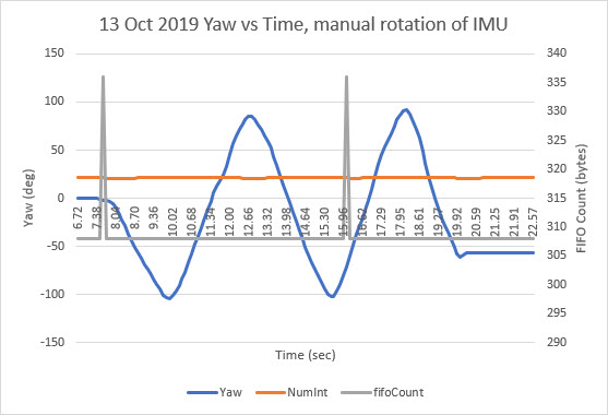
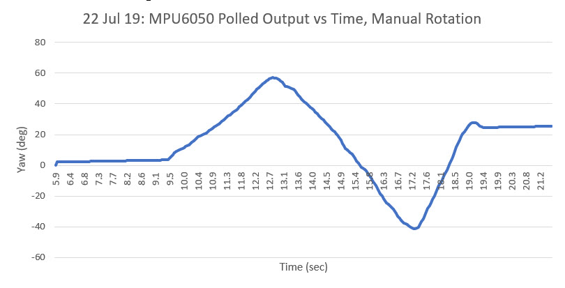
I ran another test, and this one responded perfectly for as long as I let it run (about 22 seconds). During the run I manually rotated the robot (and its attached IMU) back and forth, as shown in the following Excel plot

14 October 2019 Update:

There is clearly something not-quite-right with the way the MPU6050 reports the current length of the FIFO contents.  Here are the results from a recent run:

Aside from the fact that 22 x 28 = 616 not the reported 308, there is also the problem that after one more interrupt (23 vs 22), the reported FIFO content length didn’t go up by 14 (half the expected 28, but…) but instead by 12 bytes – what the heck?  This clearly implies that MPU interrupts aren’t entirely synchronous with actually filling the FIFO – like some sort of race condition?  In other words, the number that is reported by mpu.getFIFOCount() isn’t always an integer multiple of the packet size!  This is contrary to Homer’s assumption that the only way for mpu.getFIFOCount() to retrieve a non-integral multiple was for the FIFO to overflow. This clearly is not happening here, but I’m still getting non-integer multiple results.  Here’s another snippet from the same run:

In the above snippet, it can be seen that a 22 interrupt interval can sometimes result in 316 bytes being reported rather than the expected (ignoring for the moment the issue of a 2x error), and the ‘success’ of removing 36 bytes still resulted in a ‘bad’ yaw value computation (-179.17) 308.  In the very next loop iteration, 22 interrupts resulted in 328 bytes being reported. This time removing the excess allowed a valid yaw computation (-30.46).  So, a 22 interrupt loop interval can result in 308 (the ‘normal’ result), 316, or 328.

15 October 2019 Update:

I changed the loop() delay time from 100 mSec to 200 mSec, and (with no other changes) re-ran the test, with the following output:

The above results showed the expected 42-43 interrupt count between loop() iterations, and the expected (ignoring for the moment the 2x error factor) FIFO contents byte count of 588-616.  However, there were a couple of anomalous occurrences on two consecutive loop() iterations at 19094 and 19312 mSec.  The first one reported a FIFO contents count of 600 instead of 616 and (even after error correction) a clearly erroneous yaw value of -179.20, and the second one reported 604 bytes and (after error correction) an apparently valid yaw value of 61.54.

After an email exchange with Homer, I tried replacing this line

with this one:

In the following section of Homer’s algorithm

After this change, I re-ran the test at the 100 mSec loop() iteration delay setting with and without the above code change.  In both cases, I still got errors trapped,  as shown below (The test conditions for each run below are noted at the top of the text file)

So then, also at Homer’s suggestion, I instrumented the code to get the FIFO count rapidly several times after an error detection to see if the first mpu.getFIFOCount() occurred while data was actually being loaded into the FIFO and therefore got an erroneous count. So, I changed Homer’s code correction section to the following:

and re-ran the 100 mSec loop() iteration delay test.  What I got was this:

Wow!  the FIFO count changed!  The first mpu.getFIFOCount() at the top of the detection section got 334, and the next 3 calls all got 336!  So the first mpu.getFIFOCount() call must have hit the mpu 26/28 of the way through the packet load!

So, the MPU6050 packet load scheme isn’t atomic and there is, in fact, some sort of a race condition.  I think we have all been assuming that the MPU6050 loads the FIFO with a complete packet and then triggers an interrupt, while it appears that it is actually happening the other way around; the interrupt is triggered and then the packet is loaded into the FIFO. Most of the time this doesn’t cause a problem, but if you ‘get lucky’, the register associated with the mpu.getFIFOCount() call is read before the entire packet is loaded

16 October 2019 Update:

Homer asked me to change the code to determine exactly how long it takes to “clear the error”, which I take to mean “how long would a program have to wait for the MPU6050 to finish loading the rest of the packet into the FIFO”.  Homer sent me some sample code, which I modified slightly to produce the output Homer was looking for, as shown below:

When I ran this code, I got the following output:


21 October 2019 Update:

After several more email exchanges with Homer, he believes that he has now come up with pretty ‘bullet-proof’ way of handling MPU6050 errors, with the following subroutine

The idea behind this subroutine is to ensure that any overflow condition is detected and managed properly. The routine is completely independent of interrupts, so it can be used in a program using interrupts or polling.

Homer also sent me some test results using the program, with a variable loop delay time designed to be just below and then just above the delay required to overflow the buffer. This demonstrated that his subroutine properly handles FIFO overflow conditions, and returns valid packet data whenever possible.

In the above output, the first column is the loop delay in mSec, then the ‘Flag’ value returned by the subroutine, and then the ypr (yaw,pitch, roll) values extracted from the buffer filled by the subroutine.  As is shown, loop delay values above about 177 mSec start returning ‘2’ Flag values, indicating the routine detected (and recovered from) an overflow condition.

I replicated this experiment on my end, but discovered that for my installation, I had to use a loop delay almost exactly twice the value used by Homer (360-370 vs 177-178). The implication is that either my MPU6050 is loading the FIFO at one-half the rate of Homer’s unit, or my IMU has a buffer size twice the one being used by Homer.  Curioser and Curioser ;-).

Here’s my code and results:

Summary of results to date:


  • Homer has clearly created an effective algorithm for detecting and recovering from FIFO overflow events, and the subroutine that implements his algorithm can be used in an interrupt-driven or polling configuration.  I personally like the polling arrangement because it requires one less connecting wire, and removes the need for an ISR.
  • Both Homer and I have demonstrated that the algorithm works as designed, but the loop delay required to just trigger FIFO overflows in my configuration is almost exactly twice the delay needed for Homer’s. This needs to be explained.
  • There is still the problem of a factor of 2 error between the expected return from mpu.getFIFOCount() and the number calculated by multiplying the number of interrupts times the expected packet length. In my configuration using an interrupt-driven arrangement, a 22-interrupt loop delay resulted in a FIFO count of 308.  But, 22 x the expected packet size of 28 yields 616, not 308!  This also needs to be explained.

23 October 2019 Update:

To further investigate the ‘factor of 2 error’ problem, I went back and re-ran the initial experiment that produced the problem, just to verify that it was still there.  Here’s the entire program to recreate the results, and a partial printout of the results:

Significant points to note from the above output:

  • The time (in mSec) between adjacent output lines is about 111 mSece on average (110.5762 mSec according to Excel), and the reported number of interrupts is either 20 or 21 in almost every case (average is 20.0833333 according to Excel).  O’Scope observations confirm this is the case, as the output from the interrupt monitoring pin shows almost exactly 5 mSec between interrupts and an almost exactly 200 Hz interrupt frequency.  So, an interrupt count of 20 or 21 is reasonable, and cannot be the reason for the ‘factor of 2’ error in the FIFO buffer count.  However, there is an apparent ‘off by 2’ problem with the interrupt count, as the reported FIFO counts are consistent with interrupt counts of 22 & 23 rather than 20 or 21 as shown
  • Every so often a 22 interrupt span produces a FIFO count of 336 instead of 308 – a 28 byte difference.  In fact, over a run time of about 6.5 minutes (388,671 mSec), this phenomenon occurred 264 times, about 0.07% of the time.

The inference I draw from the above two points is that the MPU6050 chip isn’t actually loading an entire 28-byte packet during each interrupt cycle, but is in fact loading only 14 bytes each time.  With an artificially imposed 100 mSec (about 22 interrupt cycles) loop delay, the MPU loads 22 * 14 = 308 bytes.

An alternative explanation is that the MPU6050 loads complete packets into the FIFO every other interrupt. Under this scenario, it takes 11 cycles (22 interrupts) to load 11*28 = 308 bytes, and 12 cycles (24 interrupts) to load 12 * 28 = 336 bytes.

Another (and maybe even more reasonable) possibility is that the MPU6050 loads packet data into the FIFO one byte at a time, at an average rate of 14 bytes per 5 mSec, or 2.8 KBS. To the outside world, this might not be noticeable unless the application was trying to retrieve packets at the full 200 Hz.  At rates of 100Hz or less, the MPU would still have loaded at least one complete packet every time one was requested.

29 October 2019 Update:

As someone once said as both a benediction and a curse – “May you live in interesting times”.  In our ongoing investigation into the depths of MPU6050 behavior, we now have solved one mystery solved, only to encounter another one.

As I have noted several times above, there appears to be a factor of 2 mismatch between the number of interrupts counted from ISR activations and the number of bytes reported by mpu.getFIFOCount().  Either the interrupt count is off, or the FIFO count is off, and there doesn’t seem to be any other explanation.  Well, now I have determined that there is apparently a third option – that the MPU6050 only loads a packet into the FIFO on every other interrupt! This doesn’t make a whole lot of sense to me, but I now have what I believe to be irrefutable proof that this is exactly what is happening.

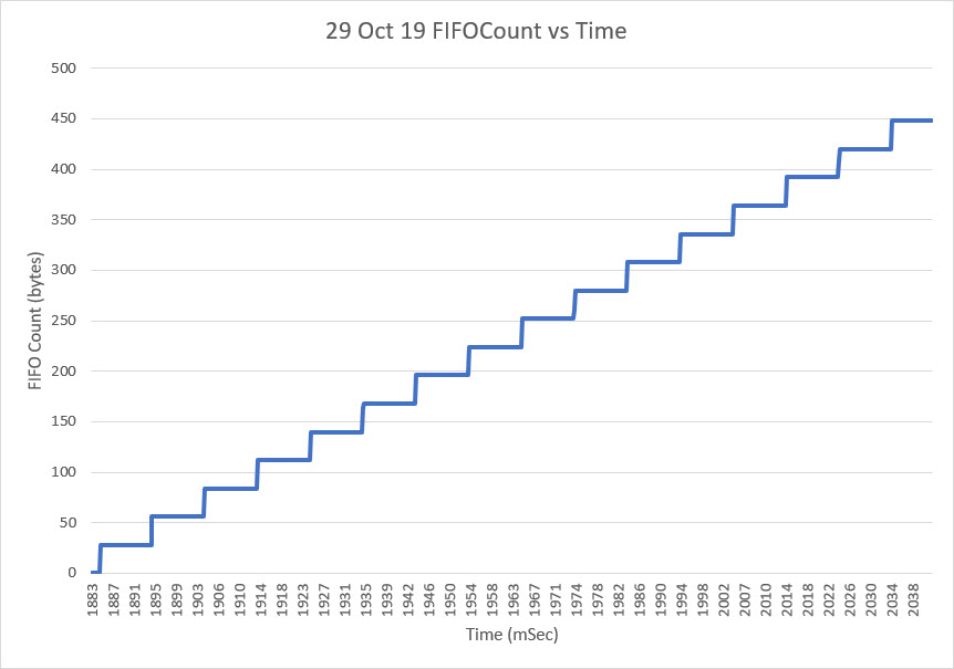
I set up a very simple program to get the FIFO byte count as rapidly as possible.  In order to avoid slowing the system down, I stored the results in a 1000-entry array during the retrieval process, and then printed out all 1000 entries at the end. Then I plotted the results in Excel as shown in the following figure:

The stairsteps in the above plot are (almost) uniformly the expected packet size of 28 bytes;  the MPU6050 is clearly loading entire 28-byte packets into the FIFO each time, contrary to one of the possibilities I had considered to explain the factor of 2 inconsistency between the interrupt count and the FIFO count.

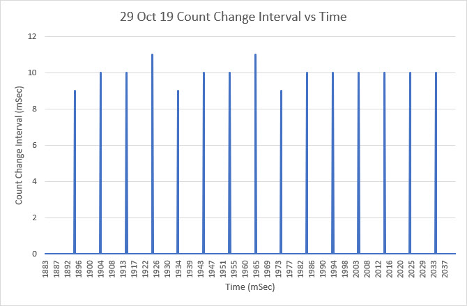
However, when I started looking at the time interval between FIFO loads, I got the following plot:

As the above plot clearly shows, the MPU6050 loads a new packet into the FIFO every 10 mSec or so (I think it is exactly 10 mSec, with the differences explained by the lack of resolution in the time axis).  But wait – the MPU6050 produces an interrupt on the Arduino interrupt pin every 5 mSec – not every 10 mSec!  So, the mystery of the ‘factor of 2’ error is now solved.  The MPU6050 loads a new packet into the FIFO every other interrupt – not every interrupt as expected. So, the interrupt count is too high by a factor of 2 when compared to the actual FIFO count.

Unfortunately (or fortunately depending on one’s point of view), that simply begs the question – why is the MPU6050 producing interrupts on a 5 mSec schedule when it only changes the FIFO count on a 10 mSec schedule?  Who knows?

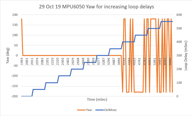
Changing the subject slightly, I got another ‘overflow proof’ version of GetCurrentFIFOPacket() from Homer Creutz to try.  I set up a small program to test it.   Since the idea was that GetCurrentFIFOPacket() would return a valid packet no matter how long it had been since the last time it was called, I set up a program to iterate through a sequence of delay times from 100 mSec to 500 mSec. For each loop delay setting I called GetCurrentFIFOPacket() multiple times and printed out the extracted yaw value and the return status from the function.

As the plot below shows, everything works swimmingly up to a loop delay of 350 mSec. Unfortunately, the wheels came off with a 400 mSec loop delay, and the packet values were all invalid after that – bummer!


06 November 2019 Update:

Holy cow!  Homer and I started this marathon project back in mid October, and we don’t seem to be any closer to nirvana than we were before.  What I can say though, is that I have learned a lot more about the MPU6050 and Jeff Rowberg’s driver software ;-).

One of the major issues we encountered with the polling method (vs interrupt-driven) is that, without the synchronization with MPU6050’s internal processes provided by the interrupt model, we can’t count on (no pun intended) the FIFO count returned by mpu.getFIFOCount() being accurate.  Depending on the timing of the call, the return value could be wildly inaccurate.  However, we discovered that two back-to-back calls to mpu.getFIFOCount() always resulted in an accurate count, although there was still a very small probability that a 3rd call would be required.  So, I created a small routine called ‘getPollingFIFOCount()’ to wrap this construct, as follows:

This function simply loops until two adjacent calls to mpu.getFIFOCount() return the same value. As always, however, there is a backup counter to force the function to exit if it gets hung up for any reason.  In the calling program I have a line like:

to set the backup loop counter value.

Another major issue with the MPU6050 is that it can overflow its packet FIFO buffer, and there doesn’t appear to be any way to prevent this, other than removing packets from the FIFO at the same rate or higher than they are loaded.  This may not be a problem for ‘high dynamics’ applications like quadcopters or balancing robots that need continuous attitude information, but for ‘slow dynamics’ applications like my wall-following robot where yaw information is only needed a few times per second, overflow becomes a practical certainty.  In an interrupt -driven environment, it might be reasonable to simply retrieve and then discard DMP packets as fast as they arrive, and then only process the latest packet when the application needs an update.  However, for a polling strategy, doing this may or may not work depending on what else is going on. So, for polling we need a way of ensuring we can retrieve a valid packet from the DMP FIFO, whether or not the FIFO has overflowed. Doing so would be trivial if the FIFO length was an integral multiple of packetSize, but it isn’t – yuk!!  So, now when the FIFO overflows, the first packet in the FIFO is guaranteed to be corrupted. The good news is, the last complete packet (i.e. the most recent information)  in the FIFO is always valid, but getting to that last good packet is non-trivial.  To summarize:

  • FIFO overflow is almost certain to happen in a ‘low dynamics’ polling-based program
  • When FIFO overflow occurs, the first packet is always corrupted, but the last one is still valid
  • The last (valid) packet isn’t the last [packetSize] bytes, due to the non-modular size of the FIFO
  • The MPU6050 DMP may start loading another packet at any time, but there will always be 10 mSec or so between packet loads
  • Any last-valid-packet retrieval algorithm must work for any loop delay time.

So, the ‘last-valid-packet-retrieval’ algorithm is something like this:

  1. Get the current packet count, using the ‘getPollingFIFOCount()’ routine above
  2. Extract [packetSize] chunks until there are less than 2* [packetSize]  bytes left. This ensures there is exactly one valid packet remaining in the FIFO.
  3. Extract one more [packetSize] chunk and return it as the result.

Note that implementation of this algorithm will require several ‘while’ loops, so there must also be provision for forcibly terminating all such loops in case some edge condition causes the normal exit condition to never be reached.  Homer and I have been creating and testing versions of this function for the last couple of weeks, without quite getting there yet.  Either they don’t handle all the edge conditions, or they are too slow as the loop delays get larger.

While I was testing my most recent concoction, I ran into a third major problem with the MPU6050 API.  I wanted to be able to remove up to 35 [packetSize] chunks (980 bytes) in one go, and I expected the mpu.getFIFOBytes() API call to manage the required chunking for me.  When I tried this trick, the getFIFOBytes() function crashed repeatedly.  Eventually I figured out that the reason it was crashing wa that it’s ‘length’ parameter is declared as a ‘uint8_t’ object and of course it couldn’t handle a value greater than 255 without choking.  I thought that was a little odd, but that maybe changing the declaration from ‘uint8_t’ to ‘uint16_t’ in MPU6050.h/cpp would solve the problem.  Nope – It turns out that, due to the way that the Arduino I2C bus operates, there is a limitation on how many bytes can be transferred across the bus in one operation, and this limit is currently set at 32 bytes.  As a result of this fundamental limitation, all the I2CDev functions that use the I2C bus also have the same underlying limitation and all of them have their length parameters declared as ‘uint8_t’. This reminds me of the old pre-scientific myth about the earth resting on the back of a turtle.  When the myth was challenged, the defender says “its no use – it’s turtles all the way down”.  In our case “it’s no use – it’s uint8_t all the way down!”.

So, I had to figure out a way around this problem, so I decided to create yet another wrapper function, this one cleverly called ‘getManyFIFOBytes()’. The idea for this would be to pull one [packetSize] chunk off the FIFO at a time using the normal ‘mpu.getFIFOBytes()’ call and place the result in a destination buffer large enough to hold the entire result.  Since it has been a (long, long) while since I last played with pointer gymnastics, I decided to write a short test program to figure out a reasonable technique.  Here is the program, and some results:

As the output shows, the ‘getManyFIFOBytes(uint16_t* buffer, uint16_t len)’ function can take an arbitrary ‘uint16_t’ length parameter and fill the destination buffer with [packetSize] (28 bytes in this case) chunks, followed by the non-modular remainder.  Although this test was done with a simulated receive buffer and simulated packet contents, I believe it will work using the actual contents of the MPU6050 FIFO and repeated calls to ‘mpu.getFIFOBytes()’ to retrieve the ‘chunks’ and any non-modular remainder bytes.

Having convinced myself that my two helper functions actually did what I wanted, I revised my latest MPU6050 test program (MPU6050_Overflow8.ino) to test the whole thing out. The test program steps through a series of loop delays from 50 to 550 msec, and takes 25 yaw measurements at each loop delay setting.  The Excel plot and a snippet of the output log from the program is shown below

  • There were no invalid packets in the entire run, so the attempt to avoid invalid packet retrieval was a success.
  • The actual loop delay per measurement pass varied quite a bit from the desired loop delay setting.  For instance the average measured loop delay for the 25 yaw measurement passes at the 200 mSec loop delay setting was actually 274.08 mSec, almost 50% higher than desired.  At the 150 mSec loop delay setting, the average loop delay was 223.88 mSec, and at the 100 mSec setting it was 133.24 mSec.  So, if the application needs 5 measurements/sec, the allowable loop delay between passes needs to be between 100 and 150 mSec.

12 November 2019 Update:

Based on some comments and data from Homer’s experiments, it appears that a FIFO reset can be done in less than 10 mSec.  This means that a packet retrieval algorithm based on a mpu.resetFIFO() call will miss at most one 10 mSec FIFO load interval, which is insignificant compared to the typical polling interval (200 mSec in my case).  So I decided to try a ‘brute force’ approach to ‘GetCurrentFIFOPacket()’ as follows:

When I first tested this algorithm, I ran into an occasional glitch where the FIFO would somehow fail to reset, resulting in a FIFO count > 28. So I added an outer loop to allow multiple shots at getting a clean FIFO reset.

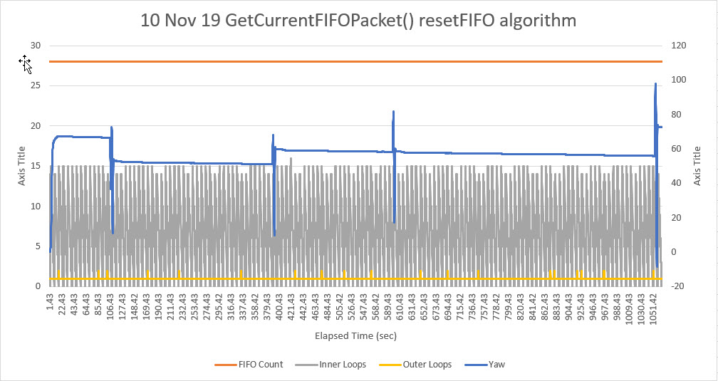
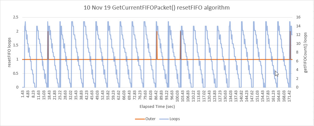
Shown below are some Excel plots from some long runs


The first plot above shows a long run (over 17 minutes) of valid yaw data (the perturbations in the yaw plot are due to occasional manual rotations of the sensor to verify that the sensor was still responding).  The interesting thing about this plot is the yellow curve, showing the ‘outer loop’ count. The only way this value can be greater than 1 is if the first mpu.resetFIFO() call fails to actually clear the FIFO, which appears to happen an average of about once per minute, or about once every 6,000 10 mSec MPU6050 FIFO cycles.

The second plot is a closeup of the first 171.42 seconds of the overall plot, showing the detail of the FIFO clear failures, occurring about once per minute.

So, it is clear that the MPU6050 has some significant behavioral quirks, especially when used in a non-interrupt-driven environment.  That being said, I believe the ‘brute force’ algorithm shown above is a reliable way of interfacing with the MPU6050 in a polling environment, and obviates the need for a separate interrupt line, and the associated ISR software.

This will probably be the last update on this subject, as I now think Homer and I have pretty much beat the MPU6050 FIFO issue to death.

Stay tuned!

Frank


Heading-based Turns Using MPU6050 and Polling vs Interrupts

Posted 06 October 2019

In previous posts I have described my efforts to integrate heading-based wall tracking into my two-wheel and four-wheel robots.  I installed a MPU6050 module into Wall-E2, my primary four-wheel robot, some time ago but was never able to make heading-based turns work for one reason or another.  In conjunction with some other experiments, I installed an MPU6050 module on my two-wheel robot so that I could investigate the issues with heading-based turns and heading-based wall tracking with a simpler hardware configuration.

With the two-wheel robot I was able to demonstrate successful heading-based wall tracking, but I was unable to port the capability to my four-wheel configuration.  Not only that, but for some reason I started having problems getting reliable yaw/heading values from my two-wheel robot configuration.  This post describes the steps I took to troubleshoot the problem, ultimately arriving at a stable polling-only (no interrupt line required) yaw/heading value retrieval algorithm suitable for both the two-wheel and four-wheel robot configurations.

Back to Basics:

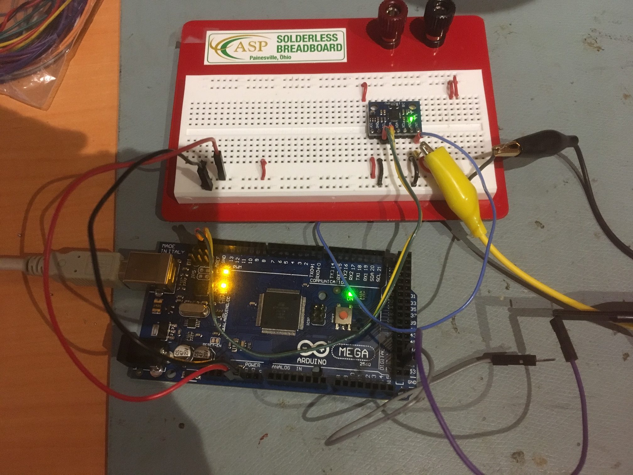
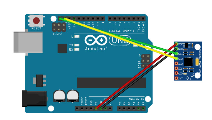
As I always do when faced with a complex problem with conflicting results, I decided to simplify the problem as much as possible.  In this case that meant reducing the hardware configuration to just a MPU6050 module and an Arduino Mega controller, as shown below:

Arduino Mega and MPU6050

On the software side, I started with the simplest possible Arduino sketch – Jeff Rowberg’s ‘MPU6050_DMP6.ino’ example, included in his latest I2CDevLib library and described in this post.

After getting everything running properly in this very basic configuration using an interrupt-driven algorithm, I moved on to working with the polling-driven arrangement, to confirm that polling was a viable strategy.  To do this I modified the hardware to disconnect the interrupt line from the MPU6050 to the controller board, and modified the software as described in this post to use a polling arrangement vs interrupts.

After confirming that this simple example worked properly and seemed stable, it was time to work my way back into the two-wheel robot hardware and software configuration (again!).  To do this I started with the basic controller/MPU6050 only hardware configuration, but running my two-wheel robot software program, modified to eliminate everything but the ‘RollingTurn()’ function that uses heading information from the MPU6050 to initiate and terminate turns.  After some false starts and blind alleys, I finally arrived at a stable software configuration demonstrating consistent heading-based turn performance using polling only – no interrupts!  the code is shown below:

In the above code, the only relevant functions are the ‘GetIMUHeading()’ and ‘RollingTurn()’ functions, as shown below:

When the ‘RollingTurn()’ function is called, it waits for mpu.dmpPacketAvailable() to return TRUE, and then it calls GetIMUHeadingDeg(), which updates a global variable (subtly named ‘global_yawval’.  This value is then used to determine turn completion.

GetIMUHeadingDeg() reads bytes from the FIFO and computes a yaw value using the retreived quaternion data.

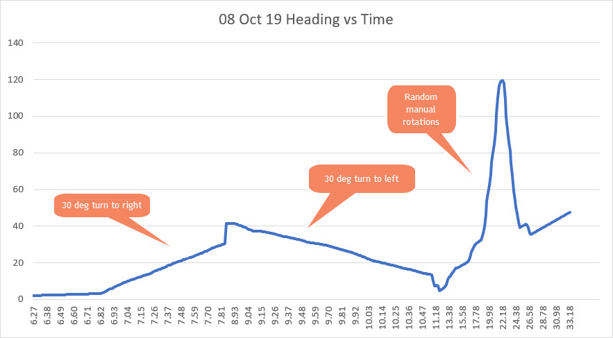
After getting everything going to my satisfaction, I added code to setup() for a 30-degree turn to the right followed by a 30-degree turn to the left, followed by an infinite loop of yaw value readouts.  The output from one test run is shown below.

Shown below are the yaw values plotted against time in Excel

The next step will be to port the updated software back into my two-wheel robot to confirm that heading-based turns can be accomplished automatically (this is something that I had going before, but…).

Stay tuned!

Frank


Polling vs Interrupt with MPU6050 (GY-521) and Arduino

Posted 04 October 2019,

In my last post I described my Arduino Mega test program to interface with the popular Invensense MPU6050 IMU and it’s GY-521 clone.  In this post I describe the interface configuration for using a polling strategy rather than relying on the IMU6050’s interrupt signal.  A polling strategy can be very useful as it is much simpler, and saves a pin connection from the MPU6050 to the controller; all that is required is +V, GND, SDA & SCL, as shown below:

With this wiring setup, the control program is shown below:

In the above program, the interrupt service routine (ISR) and the accompanying ‘attachInterrupt()’ setup function have been removed as they are no longer needed for the polling arrangement.  Instead, the program calls ‘mpu.dmpPacketAvailable()’ every time through the loop, and if a packet is available, GetIMUHeadingDeg() is called to read the packet and return a yaw value.  The rest of the code in the loop() function is the place holder for the ‘other stuff’ that the program does when it isn’t paying attention to the IMU.

In this test program, I have set this section up to execute every 100 Msec, but in my robot programs I usually set it up for a 200 Msec interval; 5 cycles/sec is plenty fast enough for a wheeled robot that uses only the IMU yaw information for turn management.

So far, this arrangement seems very stable; I have been running it now for several hours without a hiccup.

Stay tuned,

Frank


Basic Arduino/MPU6050 (GY-521) test

Posted 29 September 2019,

In my quest to figure out WTF happened to my ability to acquire real-time relative heading information on both my 2-wheel and 4-wheel robots, I have been trying to start from scratch with very simple controller/IMU hardware configurations.  After succeeding with a basic functionality demonstration using a Teensy 3.2 and a Sparkfun MPU6250 IMU breakout board, I decided the next step would be to do the same thing with an Arduino Mega controller and a GY-521 )MPU6050 clone) to more closely replicate the hardware configuration on my 2-wheel and 4-wheel robots.

As usual I started this project with a web search for basic MPU6050/Arduino examples, and I found this YouTube video showing just what I was after.  After going through the video several times to make sure I understood what was going on, I decided to try and duplicate it so I could compare my (hopefully) working demo code with my (currently non-working) robot code.

In my past efforts with the MPU6050, I had struggled with the complexities of using Jeff Rowberg’s wonderful (but quite massive and convoluted) I2CDevLib GitHub repository. There was always something that didn’t quite fit the situation, and making it fit invariably required a trip down the rabbit hole into Alice’s wonderland.  Getting the right combination of files in the right places seemed to be more a matter of luck than skill.  However, this particular video does a nice job of explicitly demonstrating what has to go where.  Essentially the magic steps are:

  • Download Jeff Rowberg’s IC2DevLib repository from GitHub into a ZIP file.
  • UnZip the repository files into a temporary folder
  • Copy the Arduino/I2CDev and Arduino/MPU6050 folders into the Arduino/Libraries folder. This makes them available to the Arduino IDE (and the VS2017/Visual Micro setup I use).
  • Open a new sketch in the Arduino IDE (or a new project in the VS/VisMicro environment) and then:
    • In the Arduino IDE select ‘File-Examples, and scroll down to the ‘Examples from Custom Libraries’ section. Then select ‘MPU6050->MPU6050_DMP6’  This will load the example code into the sketch.
    • In the VS/VM environment, select the Visual Micro Explorer (under the vMicro tab). Then click on the Examples tab, expand the ‘MPU6050’ section and then select the MPU6050_DMP6 example. This will load the code into the edit window.

Assuming you have the wiring setup correct, the example should run ‘out of the box’ with no required modifications.  However, after verifying that everything was working, I made the following changes:

  • The unmodified MPU6050_6Axis_MotionApps20.h file configures the MPU6050 DMP to send data packets to the controller at a fairly high rate – like 100Hz.  This is way too high for my robot application, so I changed the configuration to send packets at a 10Hz rate, by changing the MPU6050_DMP_FIFO_RATE_DIVISOR constant from 0x01 to 0x09 (lines 271-274) as shown below
  • The Arduino I2C library (Wire.h) has a well-known and documented flaw that causes the I2C bus to hang up on an intermittent basis, so I modified I2CDev.h lines 50-57 to use the SBWIRE library that contains timeouts to prevent this problem from happening

And the last change I made was to disable the interrupt service routine (ISR) and use a polling technique.  Instead of waiting for an interrupt, I simply poll the DMP register with

‘mpuIntStatus = mpu.getIntStatus();’

every time through the loop.  If the return value indicates that a data packet is ready, it is read; otherwise it does nothing.  This appears to be entirely equivalent to the interrupt technique as long as the loop is fast enough service the DMP’s FIFO.

30 September Update:

Well, something’s not equivalent, as the yaw values are fine for a few minutes, but then start showing up as ‘179.000’.  From my previous work I know this means that the line

mpu.getFIFOBytes(fifoBuffer, packetSize);

is getting out of sync with the DMP and isn’t reading a complete packet.  When I then changed the code back to the original interrupt-driven model, the yaw values stay valid forever.

03 October Update:

I modified the code to break the ‘put other programming stuff here’ block out of the ‘if()’ within a ‘while()’ within a ‘loop()’ structure for two reasons:

  • It gave me a headache every time I tried to figure out how it worked
  • I wanted to do ‘the programming stuff’ only once every K Msec where K was something like 100 or 200.  With the above nested structure, that would never work.

After removing extraneous comments and unused code, the resulting program is shown below:

Notes about the above program:

  • I used the SBWIRE library vs the normal Arduino WIRE library to avoid the well-known and well documented infinite blocking problems in the WIRE code.  This was accomplished by editing the I2C interface implementation section in I2Cdev.h as follows

  •  
  • I lowered the MPU6050 interrupt rate to 20Hz (I don’t need anything faster for my wall-following robot by modifying MPU6050_6AxisMotionApps20.h as follows:
  • The loop() function has just three blocks
    • if (!dmpReady) return; this bypasses everything else if the MPU6050 didn’t init correctly

    • All this section does is call GetIMUHeadingDeg() whenever an interrupt has been processed in the ISR

    • This section is the ‘everything else’ block. In my robot programs, this section runs the robot, using the yaw value output from the MPU6050 as appropriate.
  • I discovered that the local variable ‘fifoCount’ can become desynchronized from the actual FIFO count resulting in a situation where the line:

if (mpuInterrupt && fifoCount < packetSize)

in the loop() function fails with fifoCount == packetSize.  The fix for this was to remove the fifoCount comparison from the if() statement, making it just ‘if (mpuInterrupt)’.  This means the if() block will execute every time the interrupt occurs, whether or not there is data in the FIFO.

With the above modifications, the program has run for many hours with no problems, so I’m convinced I have most, if not all, the problems licked.  I’m still using the interrupt-driven version rather than the polling version I would prefer, but that’s a small price to pay for the demonstrated stability of the interrupt-driven version.

Future Work:

Next I plan to try the new MotionDriver 6.12 version of the MPU6050 DMP firmware, which is reputed to be faster, better, and more stable than the present 2.0 version.

04 October Update.

As it happens, the only thing that was required to change from MotionApps V2 to MotionApps V6.12 was to change #include “MPU6050_6Axis_MotionApps20.h” to #include “MPU6050_6Axis_MotionApps_V6_12.h” in little test program.  This compiled and ran fine, and the only difference I could see is that V6.12 has a fixed interrupt rate of about 200Hz, whereas V2.0 could be adjusted down to about 20Hz.  According to some Invensense documentation, the newer version has better/faster calibration capabilities and (maybe?) lower drift rates??

Stay Tuned


Frank


Back to the future with Wall-E2. Wall-following Part VI

Posted 13 August 2019

In my last post on this subject, I discussed the idea of using orientation information to compensate raw wall offset distance values to account for the errors associated with robot orientation.  The idea was that if I could do that, then Wall-E2 would know how far he was away from the wall regardless of orientation, and would be able to make appropriate corrections to get to and stay at a predetermined offset from the wall.

Well, it didn’t really work out that way.  After getting through the geometry analysis and the math, it turned out that in order to use the compensation algorithm, I have to know the initial robot orientation with respect to the wall, and I don’t :-(.  Without knowing this, it is basically impossible to apply the correct compensation.  For example, if the robot is originally oriented 30º away from the wall, then a ‘toward-wall’ rotation will cause the measured distance to go down, and an upward compensation is required.  However, if the robot is initially oriented toward the wall, then that same ‘toward-wall’ rotation will cause the measured distance to go up and a downward compensation is required – bummer!

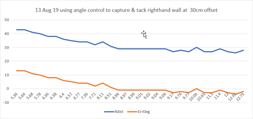
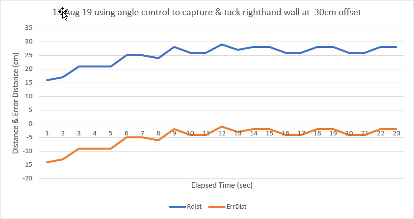
However, all is not lost;  the ability to perform relatively precise angular rotations means that I can use incremental rotations for acquiring and then tracking a predetermined offset distance.  In the acquisition phase, the robot orientation is changed in 10º increments in the appropriate direction, and an N-point slope calculation is performed to determine whether or not the current ‘cut angle’ will allow the robot to eventually reach the predetermined offset distance.   As the robot approaches the offset line, the cut angle is reduced until it is zero, in theory resulting in the robot travelling parallel to the wall at the offset distance.  At this point the robot transitions from ‘capture’ to ‘track’ mode, and the response to distance deviations becomes more robust.

This strategy was implemented using my 2-motor robot, and seems to work well once the normal crop of bugs was eradicated.  The following Excel plots show the results of two short runs where the robot first captured and then tracked a 30cm offset setting.

Capture and track a 30cm wall offset starting from the outside

Capture and track a 30cm wall offset starting from the inside

So far I have only implemented this completely for the right side, but as the left side is identical, I anticipate no problems in this regard.

Future Work:

So far I have demonstrated the ability to capture and then track a predetermined wall offset distance, starting from either inside or outside the desired offset distance. This represents a quantum leap in performance, as Wall-E2 currently can only track whatever distance it first measures – it has no capability to capture a desired offset distance.  However, there are still some ‘edge’ cases that need to be dealt with one way or the other.  For instance, if the robot orientation is too far away from parallel, the current algorithm won’t be able to rotate it enough to capture the desired offset or the measured distance will exceed the max range gate of the ping sensors (currently set at 200cm).  These conditions may not be all that deleterious, as eventually Wall-E2 will get close enough to something to trigger an avoidance response, thereby resetting the entire orientation picture (hopefully to something a little more parallel).

In addition to the wall tracking problem, the new capability to make reasonably precise angular rotations should significantly improve Wall-E2’s performance in handling ‘open-corner’ and ‘closed-corner’ situations; currently these cases are handled with timed turns, which are only correct for one floor covering type (hard vs soft) and battery state.  With the heading measurement capability, a 90º corner turn will always be (approximately) 90º whether it is on carpet or hard flooring.  In addition, now I can program in obstacle avoidance step-turns for approaching obstacles instead of relying entirely the ‘backup-and-turn’ approach.

Stay tuned!

Frank


Back to the future with Wall-E2. Wall-following Part V

Posted 08 August 2019

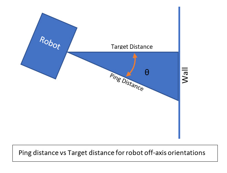
In my last post on this subject, I described some ideas for improving Wall-E2’s wall following performance by compensating for distance-to-wall errors caused by Wall-E2 not being oriented perfectly parallel to the wall.  The situation is shown in the diagram below:

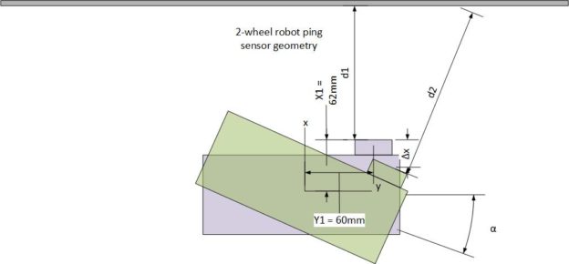
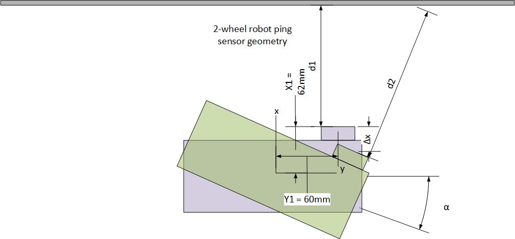
When the robot is parallel to the wall, as shown in light purple, the ping sensor measures distance d1 to the wall.  However, when it rotates to make a wall-following adjustment, the ping sensor now measures distance d2, even though the robot’s center of rotation (CR) hasn’t moved at all.  If the wall-following algorithm is based strictly on ping distance, the robot tends to wander back and forth, chasing ping measurements that don’t reflect (no pun intended) reality.  I need a way of relating the measured distance to the distance from the robot’s CR to the wall, so that wall-following adjustments can be made referenced to the CR, not to the ping sensor position on the robot.

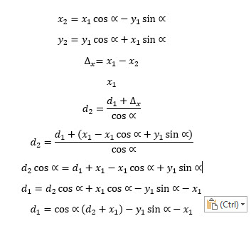
Given the above geometry, an expression can be developed to relate the perpendicular distance d1 and the measured distance d2, as shown below:

Expression relating perpendicular distance to measured distance for any rotation angle

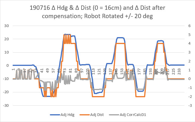
I set up an experiment where the robot was placed on a platform about 16cm away from an obstacle.  I measured the ‘ping’ distance to the obstacle as the robot was manually rotated +/- 20 deg.  Then I plotted  the data in Excel as shown below:

In the above plot, the heading values (blue line) have been normalized to the initial heading and any linear drift removed.  After correction, the robot changes heading almost exactly +/- 20 deg.  Similarly, the measured distances (orange line) values were normalized to the nominal distance of 16cm.  As can be seen, the measured distance varied about +4 to -2 cm, even though the robot center of rotation (CR) remained fixed.  Then the distance compensation expression shown above was applied, resulting in the gray line.  This shows that the compensation expression is effective in reducing angle-induced distance changes.

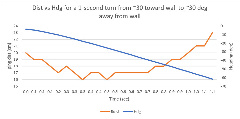
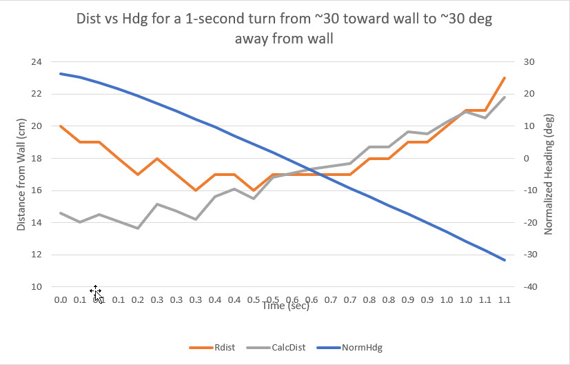
Next, I set up a ‘live’ experiment with the 2-motor robot to more closely emulate the normal operating environment.  I set up a section of ‘wall’ and had the robot make a single 60 deg turn, starting with the robot angled about 30 deg toward the wall, and ending with the robot angled about 30 deg away from the wall.  Distance measurements were taken as rapidly as possible during the turn, but not before or after the turn started.

Here’s a short video of the 2-motor robot approaching a ‘wall’ at an angle of about 30º and making a single turn of about 60º.  The entire sequence is about 3 seconds long.  The robot runs straight for about 1 sec, then turns for about 1 sec, then goes straight again for about 1 sec.

The measured ‘ping’ distances for the 1-second turn portion of the run is shown in the Excel plot below

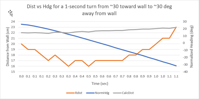
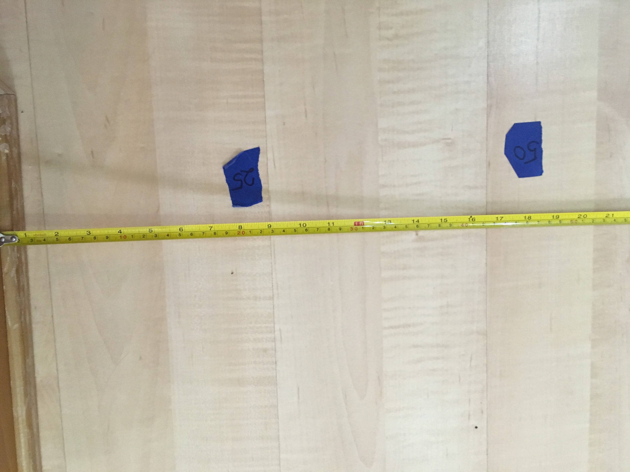
The above plot starts when the robot starts turning at about 1.2 sec into the video (the approach to the wall is not shown).  When the turn starts, the measured distance to the wall is  about 20 cm.  The measured distance decreases rapidly to about 16 cm at about 0.4 sec into the turn (about 1.6 sec into the video), and stays there for about 0.4 sec and then starts climbing rapidly to about 23 cm when the turn finishes.  However, the distance from the center of rotation (CR) of the robot to the wall changes hardly at all.  The blue painter’s tape in the background of the video has black markings each 5 cm, and it is possible to estimate the distance from the CR to the wall throughout the turn.  My estimate is that the robot’s CR starts at about 25 cm, decreases to about 22 cm at the apex of the turn, and then goes back to about 25 cm at the end of the turn.  The measured distance decreases 4 cm and then increases 8 cm while the robot’s CR decreases 3 cm and increases 3  – quite a difference, due entirely to the angle change between the robot and the wall during the turn.  After normalizing the heading values so that they reflect the angle off parallel and applying the distance compensation expression above, I got the following plot:

In the above plot, the gray line shows the corrected distance from the robot CR to the wall.  As estimated from the video earlier, the CR varies only about 1cm during the turn.  This is pretty strong evidence that the proposed distance correction scheme is correct and effective in removing distance measurement errors due to robot heading changes.

With the technique demonstrated above, I am optimistic that I can now not only improve wall tracking, but also can implement wall-following at a specific distance, say 25 cm.  The difficulty with trying to displace laterally to acquire and then lock to a specific distance is the large changes in measured difference due to the angle change needed to move toward or away from the wall made it impossible to determine where the robot’s CR actually was relative to the desired offset distance.  By (mostly) removing this orientation-induced error term, it should be feasible to determine the actions needed to approach and then track the desired offset distance.

Stay tuned!

Frank

08 February 2020 Update:

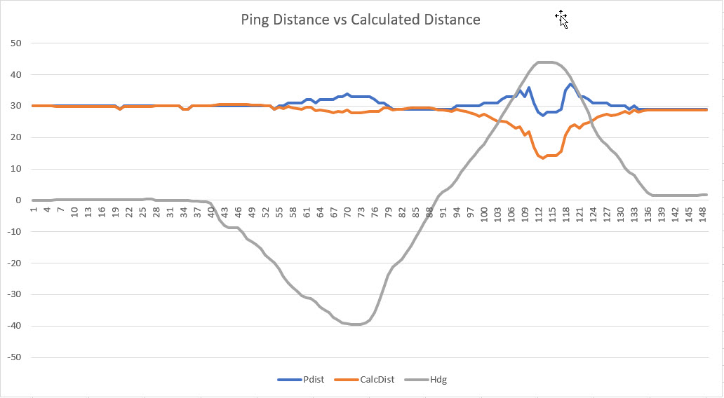
As I continued my campaign to integrate heading information into my wall-following robot algorithm, my efforts to compensate ‘ping’ distances for off-parallel robot orientations with respect to the nearest wall kept failing, and I didn’t know why.  I had gone through the math several times and was convinced it was valid, and as the plot above showed, it should work.

So, I made another run at it, completely redoing the math from the ground up – and running some more test in my ‘local range’ (aka my office).  Still no joy – no matter what I did, the math  seemed to be overcompensating, as shown in the plot below:

Ping Distance vs Calc Distance for two heading changes

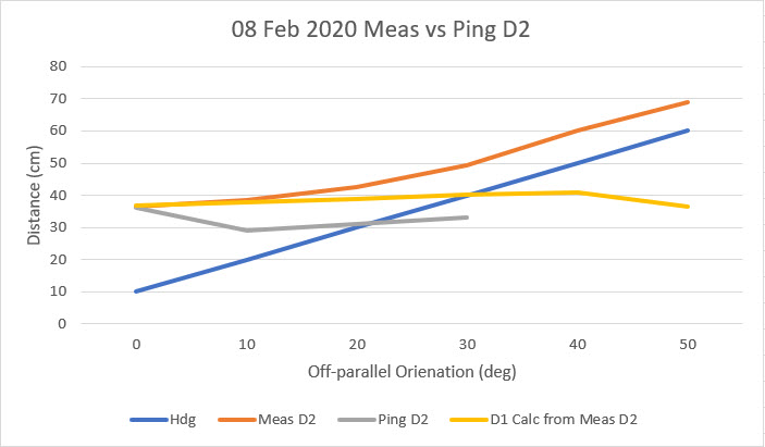
This plot (and others like it)  convinced me that I was still missing something fundamental.  As I often do, I was thinking about this in bed while drifting off to sleep, and I realized that I might be able to determine the culprit by cheating; I would place the robot at a set distance from the wall, and carefully rotate it manually over a compass rose.  At each heading I would manually measure the distance from the ping sensor to the wall, perpendicular to the plane of the sensor (i.e. I would physically measure the distance I would expect the ping sensor to report), and also record the ‘ping’ distance reported by the sensor.  With just a few measurements the problem became obvious; the ‘ping’ distance for slant angles to the wall do not even remotely resemble the actual physical distance – it is much less, as shown below.

As can be seen , the compensation algorithm actually works quite well, when dealing with the physically measured slant range.  However, because the ‘ping’ distance loses accuracy very rapidly off-parallel angles beyond about 20 degrees, the compensation algorithm is ineffective.  A classic case of ‘GIGO’.

After performing the above experiment, I was still left with the mystery of why the compensation algorithm appeared to work so well before – WTF?  So, I went back and very carefully examined the previous plot and the underlying data, and discovered I’d made another classic experimental error – The ‘Calculated Distance’ data was plotted on the wrong scale.  When plotted on the correct scale, the plot changes to the one shown below:

Previous plot with ‘Calc Distance’ plotted on the correct scale

Now it is clear that the calculated compensation using ‘ping’ distances is not at all useful.

So, the bottom line on all of this it that the effort to apply a heading-based ping distance compensation was doomed to failure from the start, because the distance reported by the ping sensor is wildly inaccurate for off-perpendicular geometries.  The good news is that now at least I know why the compensation effort was doomed to fail!

In the meantime, I independently developed a technique for determining the heading required for orienting the robot parallel to the wall as the heading associated with the minimum ping distance achieved by swinging the robot back and forth. This technique utilizes the ping sensors in the realm where they are most accurate, and does away entirely with the need for compensation.

Stay tuned!

Frank


Back to the future with Wall-E2. Wall-following Part IV

Posted 30 April 2019

In two previous posts (here & here) I described my efforts to upgrade Wall-E2’s wall following performance using a PID control algorithm.  The results of my efforts to date in this area have not been very spectacular – a better description might actually be ‘dreadful’ :-(.

After some additional analysis, I came to believe that the reason the PID approach doesn’t work very well is a fundamental feature of the way Wall-E2 measures distance to the nearest wall.  Wall-E2 has two acoustic sonar units fixed to its upper deck, and they measure the distance perpendicular to the robot’s longitudinal axis.  What this means, however, is that when the robot is angled with respect to the nearest wall, the distance measured isn’t the perpendicular distance, but rather the hypotenuse of the right triangle with the right angle at the wall.  So, when Wall-E2 turns toward or away from the wall, the measured distance increases even though the robot hasn’t actually moved toward or away.  Conversely, if the robot is angled in toward the wall and then turns to be parallel, the measured distance decreases even if the robot hasn’t moved at all relative to that wall. The situation is shown in the sketch below:

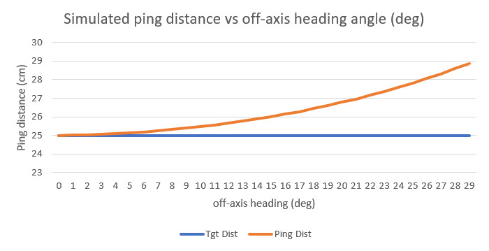
Using Excel, I ran a simulation of the ping distance versus the actual distance for a range of angle offsets from 0 to 30 degrees, as shown below:

As shown above, the ping distance for a constant 25 cm offset ranges from 25 (robot longitudinal axis parallel to the wall) to almost 29 cm for a 30 degree off-axis heading. These values translate to a percentage error of zero to approximately 15%, independent of the initial parallel distance.

So, it becomes obvious why a standard PID algorithm has trouble; if the ping distance goes up slightly, the PID algorithm attempts to compensate by turning toward the wall.  However, this causes the ping distance to increase rather than decrease, causing the algorithm to command an even greater angle toward the wall, which in turn causes a further increase in ping distance – entirely backward.  The reverse happens for an initial decrease in the ping distance starting from a parallel orientation.  The algorithm commands a turn away from the wall, which causes the ping distance to increase immediately, even though the actual distance hasn’t changed.  This causes the algorithm to seriously overcorrect in one case, and seriously undercorrect in the other.   Not good.

What I need is a way to compensate for the changes in ping distance caused by Wall-E2’s angular orientation with respect to the wall being tracked. If Wall-E2 is oriented parallel to the wall, then no correction is needed; if not,then a correction is required.  Fortunately for the good guys, Wall-E2 now has a way of providing the needed heading information, with the integration of the MPU6050-based 6DOF IMU module described in this post from last September.

To investigate this idea, I modified an old test program to have Wall-E2 perform a series of mild S-turns in my test hallway while capturing heading and ping distance data.  The S-turns were tweaked so that Wall-E2 stayed a fairly constant 50 cm from the right-hand wall, as shown in the following movie clip.


Start of test area showing tape measure for offset distance measurement

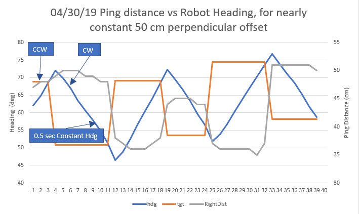
Using Excel, I plotted the reported ping distance, the commanded heading, and the actual heading versus time, as shown below:

In the above plot, the initial CCW turn (away from the wall) was a 10° change, and all the rest were approximately 20° to maintain a more-or-less straight line.  At the end of the second (the first CW turn) and subsequent heading changes, there is an approximately 0.5 sec straight period, during which no data was captured.  As can be seen, the ping distance (gray curve) goes up slightly as the first CCW turn starts, then levels off during the changeover from CCW to CW turns, and then precipitously declines as the CW turn sweeps the ping sensor toward the perpendicular point.  Part of this decline is actual distance change caused by the 0.5 sec straight period that moves the robot toward the wall.  After the next (CCW) heading change is commanded, the robot starts to turn away from the wall causing the ping distance to increase, but this is partially cancelled by the fact that the robot continues to travel toward the wall during the S-turn. As soon as the robot gets parallel to the wall, then the ping distance goes up quickly as the heading continues to change in a CCW direction.  This behavior repeats for each S-turn until the end of the run.

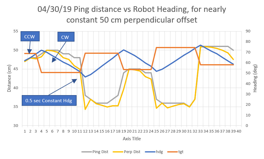
As an exercise, I added another column to the spreadsheet – “perpendicular distance”, and set up a formula to compute the adjusted distance from the robot to the wall, using the recorded angular offset.  This computation presumes that the robot started off parallel to the wall (confirmed via the video clip).  The result is shown on the yellow line in the plot below:

Ping distance and heading vs time, with calculated perpendicular distance added


As can be seen from the above plot and video, the compensated distance looks like it might be a good match with the perpendicular distance estimated from the video. For instance, at 17 sec into the video, the robot has just finished the first clockwise turn and straight run, and is just starting the second counter-clockwise turn.  At this point the robot is oriented parallel to the wall, and the ping distance and the perpendicular distance should match. The video shows that distance should be about 33-35 cm, and the recorded ping distance at this point is 36 cm.  However, the calculated distance went directly from 45 cm at point 11 to 34 cm at point 12 and basically stayed at that value before changing rapidly from 34 to 45 over points 19 & 20.  Again at 19 seconds into the video, the robot is approximately 42-44 cm from the wall and parallel to it; both the actual ping distance and the calculated perpendicular distance agree at this point at 45 cm – a close match to the estimate from the video.

So now the question is – can I use the calculated perpendicular wall distance to assist wall-following operations?  A significant issue may be knowing when the robot is actually parallel to the wall, to establish a heading baseline for compensation calcs.

When is the robot parallel to the wall?

A unique feature of the point or points where the robot is parallel to the wall is that the ping distance and the calculated distance are equal.  However, that’s a bit of ‘chicken and the egg’ as one has to know the robot is parallel in order to use an offset angle of 0 degrees for the compensation calc to work out.  Since the heading information available from the MPU6050 IMU is only relative, the heading value for the parallel condition can be anything, and can vary arbitrarily from run to run.  So, what to do?  One thought would be to have the robot make a short S-turn at the start of any tracking run to establish the heading for which the ping distance goes through a minimum or maximum – the heading for the max/min point would be the parallel heading. From there on, that heading should be reliably constant until the next time the robot’s power is cycled.  Of course, a new parallel heading value would be required each and every time Wall-E2’s tracking situation changes (obstacle recovery, step-turns and reversals at the end of a hallway, changing from the left wall to the right one, etc).  Maybe a hybrid mode would be feasible, whereby the robot uses uncompensated heading-based S-turns instead of the current ‘bang-bang’ system for initial wall tracking, shifting to a compensation algorithm after a suitable parallel heading is determined.

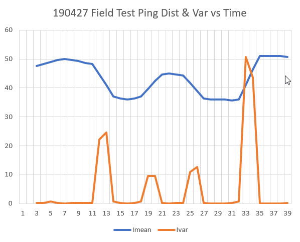
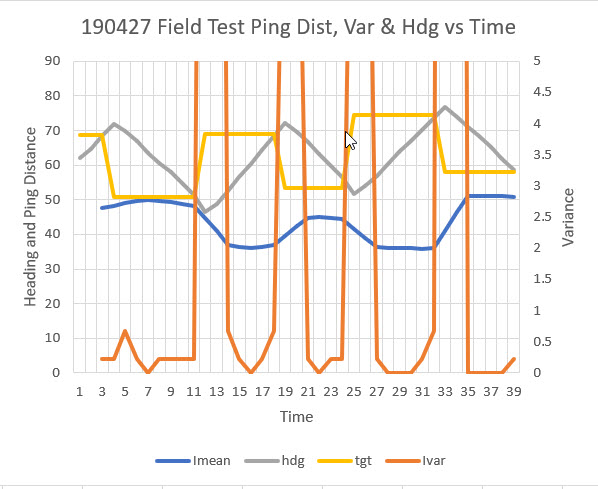
Looking at the above plots, it may not be all that useful to look for maxima and/or minima, as there are multiple headings for which the ping distance is constant, so which one is the parallel heading?  Thinking about ways to rapidly find the parallel heading, it occurred to me that my previous work on quickly finding the mathematical variance of a set of values might be useful here.  I plugged the above ping distance numbers into the Excel spreadsheet I used before, and got the following plot of ping distance and 3-element running variance vs time.

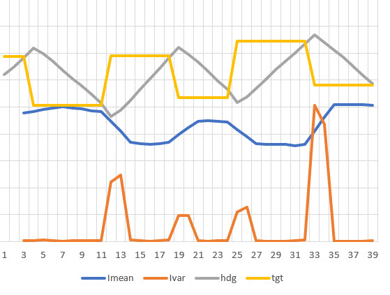
So, looking at the above plot, it is encouraging that a 3-point running variance calculation shows near-zero values when the robot is most probably parallel or nearly parallel to the wall.  Adding the heading information to the spreadsheet gives the plot shown below

and now it is clear that the large variance values are associated with the changes from one heading to another, and the low variance values are associated with the middle section of each linear heading change (S-turn) segment.  If I further enhance the plot by putting the variance plot on a secondary scale and zooming in on the low variance sections, we get the plot shown below:


Variance scale modified to show 0-5 range only

In the above plot, the variance line is zoomed in to the 0-5 range only, emphasizing the 0-0.5 unit variance range.  In this plot it can be seen that the variance actually has a distinct minimum very near zero at time points 7, 16, 22, 28-30, and 35-38.  These time values correspond to robot heading values of 64, 61, 63, 61-67. and 70-65.  Discarding the last set as bad data (this is where the robot literally ‘hit the wall’ at the end of the run), we can compute an approximate parallel heading value as the average of all these values, or the average of 64, 61, 63, 64 (average of 61-67) = 63 degrees.  From the video we can see that the robot started out parallel to the wall, and the first heading reading was 62 degrees – a very good match to the calculated parallel heading value.

The next step, I think, is to run some more field tests against a wall, with wall-following and heading assist integrated into the code.

Frank


MPU6050 IMU Motor Noise Troubleshooting

Posted 24 July 2019

For a while now I’ve been investigating ways of improving the wall following performance of my autonomous wall-following robot Wall-E2.  At the heart of the plan is the use of a MPU6050 IMU to sense relative angle changes of the robot so that changes in the distance to the nearest wall due only to the angle change itself can be compensated out, leaving only the actual offset distance to be used for tracking.

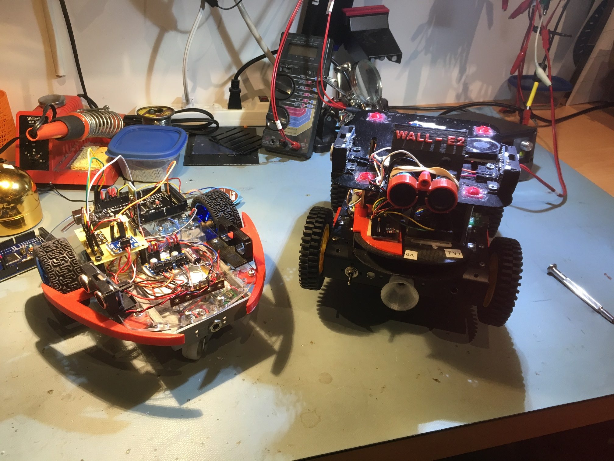
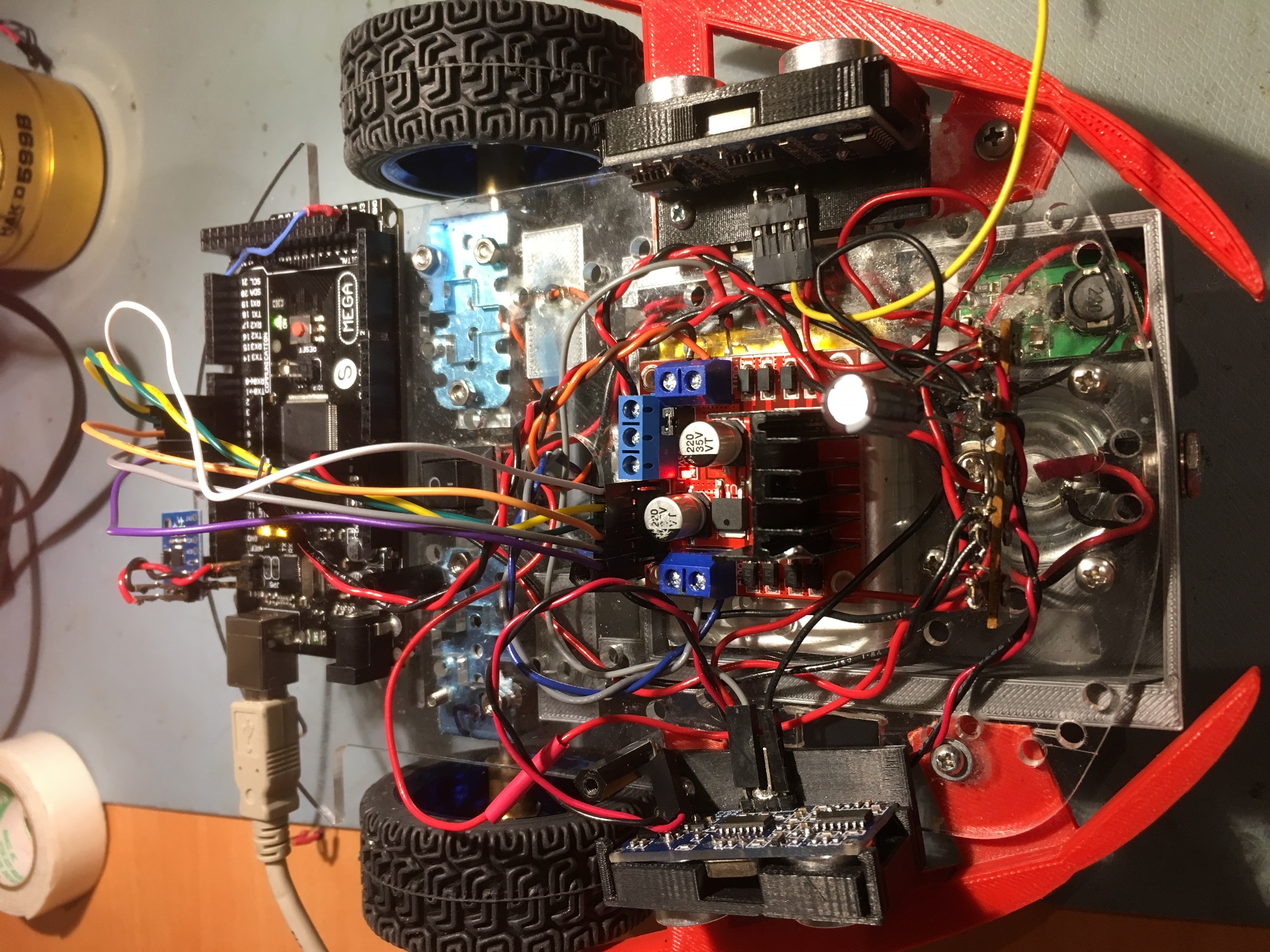
As the test vehicle for this project, I am using my old 2-motor robot, fitted with new Pololu 125:1 metal-geared DC motors and Adafruit DRV8871 motor drivers, as shown in the photo below.

2-motor test vehicle on left, Wall-E2 on right

The DFRobots MPU6050 IMU module is mounted on the green perfboard assembly near the right wheel of the 2-motor test robot, along with an Adafruit INA169 high-side current sensor and an HC-05 Bluetooth module used for remote programming and telemetry.

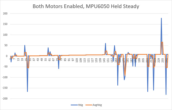
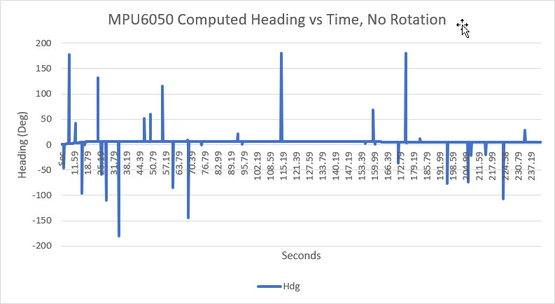
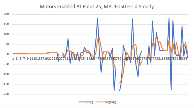
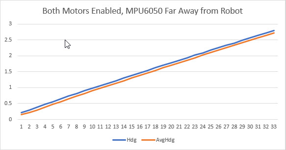
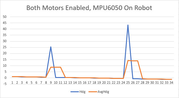
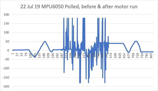
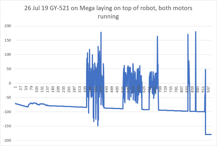
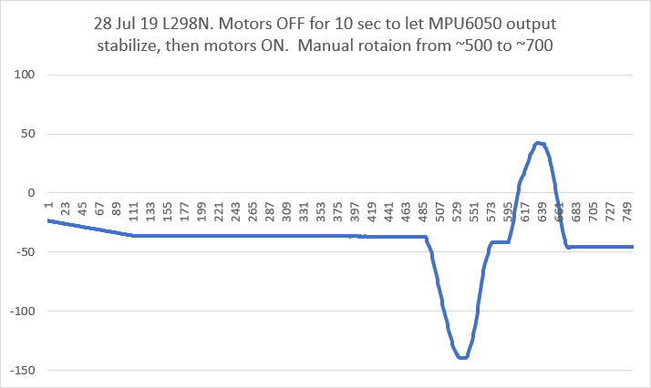
This worked great at first, but then I started experiencing anomalous behavior where the robot would lose track of the relative heading and start turning in circles.  After some additional testing, I determined that this problem only occurred when the motors were running.  It would work fine as long as the motors weren’t running, but since the robot had to move to do its job, not having the ability to run the motors was a real ‘buzz-kill’.  I ran some experiments on the bench to demonstrate the problem, as shown in the Excel plots below:

Troubleshooting:

There were a number of possibilities for the observed behavior:

  1. The extra computing load required to run the motors was causing heading sensor readings to get missed (not likely, but…)
  2. Motor noise of some sort was feeding back into the power & ground lines
  3. RFI created by the motors was getting into the MPU6050 interrupt line to the Arduino Mega and causing interrupt processing to overwhelm the Mega
  4. RFI created by the motors was interfering with I2C communications between the Mega and the MPU6050
  5. Something else

Extra Computing Load:

This one was pretty easy to eliminate.  The main loop does nothing most of the time, and only updates system parameters every 200 mSec.  If the extra computing load was the problem, I would expect to see no ‘dead time’ between adjacent adjustment function blocks.  I had some debug printing code in the program that displayed the result of the ‘millis()’ function at various points in the program, and it was clear that there was still plenty of ‘dead time’ between each 200 mSec adjustment interval.

Motor noise feeding back into power/ground:

I poked around on the power lines with my O’scope with the motors running and not running, but didn’t find anything spectacular; there was definitely some noise, but IMHO not enough to cause the problems I was seeing.  So, in an effort to completely eliminate this possibility, I removed the perfboard sub-module from the robot entirely, and connected it to a separate Mega microcontroller. Since this setup used completely different power circuits (the onboard battery for the robot, PC USB cable for the second Mega), power line feedback could not possibly be a factor.  With this setup I was able to demonstrate that the MPU6050 output was accurate and reasonable until I placed the perfboard sub-module in close proximity to the robot; then it started acting up just as it did when mounted on the robot.

So it was clear that the interference is RFI, not conducted through any wiring.

RFI created by the motors was getting into the MPU6050 interrupt line to the Arduino Mega and causing interrupt processing to overwhelm the Mega

This one seemed very possible.  The MPU6050 generates interrupts at a 20Hz rate, but I only use measurements at a 5Hz (200mSec) rate.  Each interrupt causes the Interrupt Service Routine (ISR) to fire, but the actual heading measurement only occurs every 200 mSec. I reasoned that if motor-generated RFI was causing the issue, I should see many more activations of the ISR than could be explained by the 20Hz MPU6050 interrupt generation rate.  To test this theory, I placed code in the ISR that pulsed a digital output pin, and then monitored this pin with my O’scope.  When I did this, I saw many extra ISR activations, and was convinced I had found the problem.  In the following short video clip, the top trace is the normal interrupt line pulse frequency, and the bottom trace is the ISR-generated pulse train.  In normal operation, these two traces would be identical, but as can be seen, many extra ISR activations are occurring when the motors are running.

So now I had to figure out what to do with this information.  After Googling around for a while, I ran across some posts that described using the MPU6050/DMP setup without using the interrupt output line from the module; instead, the MPU6050 was polled whenever a new reading was required.  As long as this polling takes place at a rate greater than the normal DMP measurement frequency, the DMP’s internal FIFO shouldn’t overflow.  If the polling rate is less than the normal rate, then FIFO management is required.  After thinking about this for a while, I realized I could easily poll the MPU/DMP at a higher rate than the configured 20Hz rate by simply polling it each time through the main loop – not waiting for the 200mSec/5Hz motor speed adjustment interval.  I would simply poll the MPU/DMP as fast as possible, and whenever new data was ready I would pull it off the FIFO and put it into a global variable.  The next time the motor adjustment function ran, it would use the latest relative heading value and everyone would be happy.

So, I implemented this change and tested it off the robot, and everything worked OK, as shown in the following Excel plot.

And then I put it on the robot and ran the motors

Crap!  I was back to the same problem!  So, although I had found evidence that the motor RFI was causing additional ISP activations, that clearly wasn’t the entire problem, as the polling method completely eliminates the ISP.

RFI created by the motors was interfering with I2C communications between the Mega and the MPU6050

I knew that the I2C control channel could experience corruption due to noise, especially with ‘weak’ pullup resistor values and long wire runs.  However, I was using short (15cm) runs and 2.2K pullups on the MPU6050 end of the run, so I didn’t think that was an issue.  However, since I now knew that the problem wasn’t related to wiring issues or ISR overload, this was the next item on the list.  So, I shortened the I2C runs from 15cm to about 3cm, and found that this did indeed suppress (but not eliminate) the interference.  However, even with this modification and with the MPU6050 module located as far away from the motors as possible, the interference was still present.

Something else

So, now I was down to the ‘something else’ item on my list, having run out of ideas for suppressing the interference.  After letting this sit for a few days, I realized that I didn’t have this problem (or at least didn’t notice it) on my 4-motor Wall-E2 robot, so I started wondering about the differences between the two robot configurations.

  1. Wall-E2 uses plastic-geared 120:1 ‘red cap’ motors, while the 2-motor robot uses pololu 125:1 metal-geared motors
  2. Wall-E2 uses L298N linear drivers while the 2-motor version uses the Adafruit DRV8871 switching drivers.

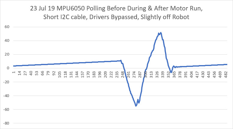
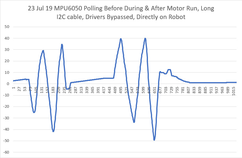
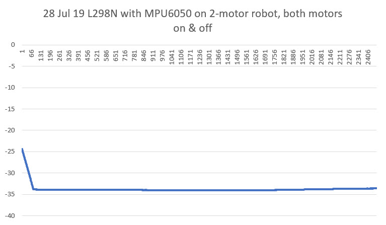
So, I decided to see if I could isolate these two factors and see if it was the motors, or the drivers (or both/neither?) responsible for the interference. To do this, I used my new DPS5005 power supply to generate a 6V DC source, and connected the power supply directly to the motors, bypassing the drivers entirely.  When I did this, all the interference went away!  The motors aren’t causing the interference – it’s the drivers!

In the first plot above, I used a short (3cm) I2C wire pair and the module was located near, but not on, the robot. As can be seen, no interference occurred when the motors were run.  In the second plot I used a long (15cm) I2C wire pair and mounted the module directly on the robot in its original position.  Again, no interference when the motors were run.

So, at this point it was pretty definite that the main culprit in the MPU6050 interference issue is the Adafruit DRV8871 switch-mode driver.  Switch-mode drivers are much more efficient than L298N linear-mode drivers, but the cost is high switching transients and debilitating interference to any I2C peripherals.

As an experiment, I tried reducing the cable length from the drivers to the motors, reasoning that the cables must be acting like antennae, and reducing their length should reduce the strength of the RFI.  I re-positioned the drivers from the top surface of the robot to the bottom right next to the motors, thereby reducing the drive cable length from about 15cm to about 3 (a 5:1 reduction).  Unfortunately, this did not significantly reduce the interference.

So, at this point I’m running out of ideas for eliminating the MPU6050 interference due to switch-mode driver use.

  • I read at least one post where the poster had eliminated motor interference by eliminating the I2C wiring entirely – he used a MPU6050 ‘shield’ where the I2C pins on the MPU6050 were connected directly to the I2C pins on the Arduino microcontroller.  The poster didn’t mention what type of motor driver (L298N linear-mode style or DRV8871 switch-mode style), but apparently a (near) zero I2C cable length worked for him.  Unfortunately this solution won’t work for me as Wall-E2 uses three different I2C-based sensors, all located well away from the microcontroller.
  • It’s also possible that the motors and drivers could be isolated from the rest of the robot by placing them in some sort of metal box that would shield the rest of the robot from the switching transients caused by the drivers.  That seems a bit impractical, as it would require metal fabricating unavailable to me.  OTOH, I might be able to print a plastic enclosure, and then cover it with metal foil of some sort.  If I go this route, I might want to consider the use of optical isolators on the motor control lines, in order to break any conduction path back to the microcontroller, and capacitive feed-throughs for the power lines.

27 July 19 Update:

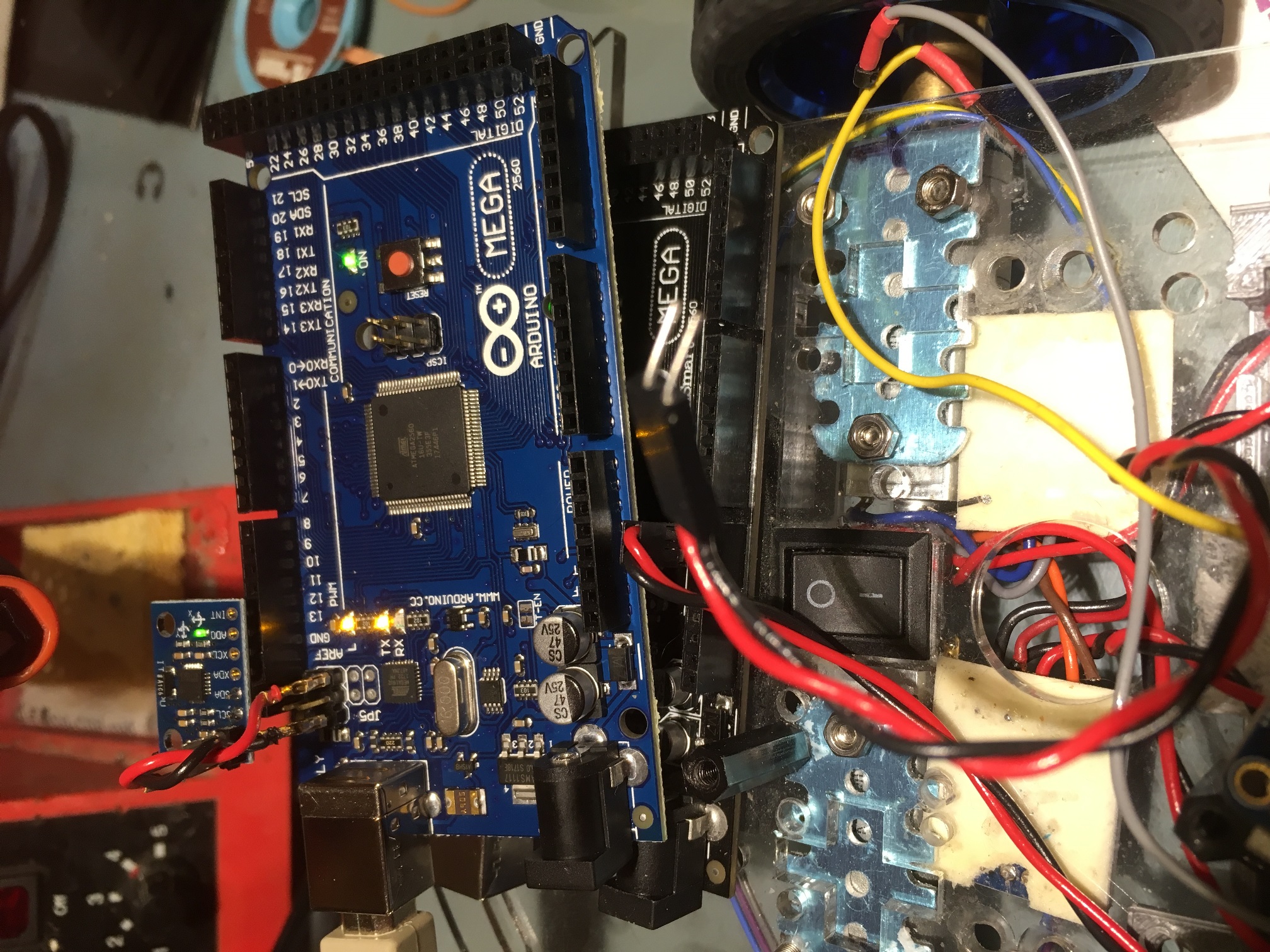
I received a new batch of GY-521 MPU6050 breakout boards, so I decided to try a few more experiments.  With one of the GY-521 modules, I soldered the SCL/SDA header pins to the ‘bottom’ (non-label side) and the PWR/GND pins to the ‘top’.  With this setup I was able to plug the module directly into the Mega’s SCL/SDA pins, thereby reducing the I2C cable length to zero.  The idea was that if the I2C cable length was contributing significantly to RFI susceptibility, then a zero length cable should reduce this to the minimum  possible, as shown below:

MPU6050 directly on Mega pins, normal length power wiring

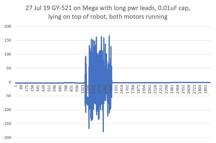
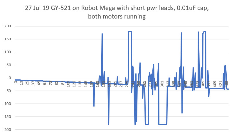
In the photo above, the Mega with the MPU6050 connected is sitting atop the Mega that is running the motors. The GND and +5V leads are normal 15cm jumper wires.  As shown in the plots below, this configuration did reduce the RFI susceptibility some, but not enough to allow normal operation when lying atop the robot’s Mega.

GY-521 MPU6050 module mounted directly onto Mega, normal length power leads

I was at least a little encouraged by this plot, as it showed that the MPU6050 (and/or the Mega) was recovering from the RFI ‘flooding’ more readily than before.  In previous experiments, once the MPU6050/Mega lost sync, it never recovered.

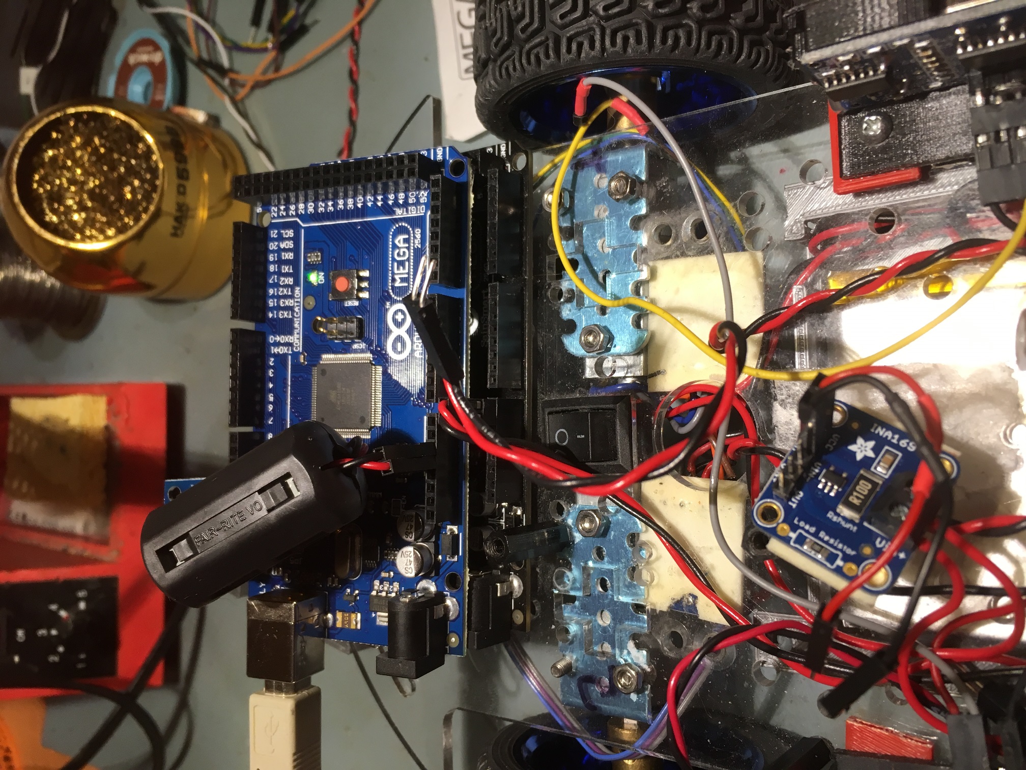
Next I tried looping the power wiring around an ‘RF choke’ magnetic core to see if raising the effective impedance of the power wiring to high-frequency transients had any effect, as shown in the following photo.

GND & +5V leads looped through an RF Choke.

Unfortunately, as far as I could tell this had very little positive effect on RFI susceptibility.

Next I tried shortening the GND & +5V leads as much as possible.  After looking at the Mega pinout diagram, I realized there was GND & +5V very close to the SCL/SDA pins, so I fabricated the shortest possible twisted-pair cable and installed it, as shown in the following photo.

MPU6050 directly on Mega pins, shortest possible length power wiring

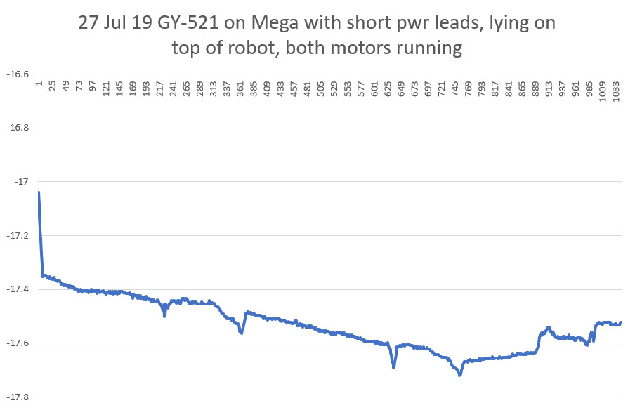
With this configuration, I was actually able to get consistent readings from the MPU6050, whether or not the motors were running – yay!!

In the plot above, the vertical scale is only from -17 deg to -17.8 deg, so all the variation is due to the MPU6050, and there is no apparent deleterious effects due to motor RFI – yay!

So, at this point it’s pretty clear that a significant culprit in the MPU6050’s RFI susceptibility is the GND/+5V and I2C cabling acting as antennae and  conducting the RFI into the MPU6050 module.  Reducing the effective length of the antennas was effective in reducing the amount of RFI present on the module.

With the above in mind, I also tried adding a 0.01uF ‘chip’ capacitor directly at the power input leads, thinking this might be just as effective (if not more so) than shortening the power cabling.  Unfortunately, this experiment was inconclusive. The normal length power cabling with the capacitor seemed to cause just as much trouble as the setup without the cap, as shown in the following plot.

Having determined that the best configuration so far was the zero-length I2C cable and the shortest possible GND/+5V cable, I decided to try moving the MPU6U6050 module from the separate test Mega to the robot’s Mega. This required moving the motor drive lines to different pins, but this was easily accomplished.  Unfortunately, when I got everything together, it was apparent that the steps taken so far were not yet effective enough to prevent RFI problems due the switch-mode motor drivers

The good news, such as it is, is that the MPU6050/Mega seems to recover fairly quickly after each ‘bad data’ excursion, so maybe we are most of the way there!

As a next step, I plan to replace the current DRV8871 switch-mode motor drivers with a single L298N dual-motor linear driver, to see if my theory about the RFI problem being mostly due to the high-frequency transients generated by the drivers and not the motors themselves.  If my theory holds water, replacing the drivers should eliminate (or at least significantly suppress) the RFI problems.

28 July 2019 Update:

So today I got the L298N driver version of the robot running, and I was happy (but not too surprised) to see that the MPU6050 can operate properly with the motors ON  or OFF when mounted on the robot’s Mega controller, as shown in the following photo and Excel plots

2-motor robot with L298N motor driver installed.

However, there does still seem to be one ‘fly in the ointment’ left to consider.  When I re-installed the wireless link to allow me to reprogram the 2-motor robot remotely and to receive wireless telemetry, I found that the MPU6050 exhibited an abnormally high yaw drift rate unless I allowed it to stabilize for about 10 sec after applying power and before the motors started running, as shown in the following plots.

2-motor robot with HC-05 wireless link re-installed.

I have no idea what is causing this behavior.

31 July 2019 Update

So, I found a couple of posts that refer to some sort of auto-calibration process that takes on the order of 10 seconds or so, and that sounds like what is happening with my project.  I constructed the following routine that waited for the IMU yaw output values to settle

This was very effective in determining when the MPU6050 output had settled, but it turned out to be unneeded for my application.  I’m using the IMU output for relative yaw values only, and over a very short time frame (5-10 sec), so even high yaw drift rates aren’t deleterious.  In addition, this condition only lasts for a 10-15 sec from startup, so not a big deal in any case.

At this point, the MPU6050 IMU on my little two-motor robot seems to be stable and robust, with the following adjustments (in no particular order of significance)

  • Changed out the motor drivers from 2ea switched-mode DRV8871 motor drivers to a single dual-channel L298N linear mode motor driver.  This is probably the most significant change, without which none of the other changes would have been effective.  This is a shame, as the voltage drop across the L298N is significantly higher than with the switch-mode types.
  • Shortened the I2C cable to zero length by plugging the GY-521 breakout board directly into the I2C pins on the Mega.  This isn’t an issue on my 2-motor test bed, but will be on the bigger 4-motor robot
  • Shortened the IMU power cable from 12-15cm to about 3cm, and installed a 10V 1uF capacitor right at the PWR & GND pins on the IMU breakout board.  Again, this was practical on my test robot, but might not be on my 4-motor robot.
  • Changed from an interrupt driven architecture to a polling architecture.  This allowed me to remove the wire from the module to the Mega’s interrupt pin, thereby eliminating that possible RF path.  In addition, I revised the code to be much stricter about using only valid packets from the IMU.  Now the code first clears the FIFO, and then waits for a data ready signal from the IMU (available every 50 mSec at the rate I have it configured for).  Once this signal is received, the code immediately reads a packet from the FIFO if and only if it contains exactly one packet (42 bytes in this configuration).  The code shown below is the function that does all of this.

Here’s a short video of the robot making some planned turns using the MPU6050 for turn management.  In the video, the robot executes the following set of maneuvers:

  1. Straight for 2 seconds
  2. CW for 20 deg, starting an offset maneuver to the right
  3. CCW for 20 deg, finishing the maneuver
  4. CCW for 20 deg, starting an offset maneuver to the left
  5. CW for 20 deg, finishing the maneuver
  6. 180 deg turn CW
  7. Straight for 3 sec
  8. 20 deg turn CCW, finishing at the original start point

So, I think it’s pretty safe to say at this point that although both the DFRobots and GY-521 MPU6050 modules have some serious RFI/EMI problems, they can be made to be reasonably robust and reliable, at least with the L298N linear mode motor drivers.  Maybe now that I have killed off this particular ‘alligator’, I can go back to ‘draining the swamp’ – i.e. using relative heading information to make better decisions during wall-following operations.

Stay tuned!

Frank


Integrating Time, Memory, and Heading Capability, Part VIII

Posted 13 September 2018

Now that I have worked out most of the problems associated with the MPU6050 6DOF IMU module, it was time to integrate the new heading-based turn algorithm into the main Wall-E2 operating system.   As I have done in many past projects over the last half-century or so, I started this process by documenting the entire OS, with particular emphasis on how Wall-E2 currently navigates around his world.   When I started doing this in the 1970’s, the medium I used was an MIT Engineering notebook, hand-written in ink.   Over the ensuing decades the medium has changed, but not the basic idea – the process of putting coherent sentences and paragraphs onto paper (or screen) forces me to think through what is – and is not – important/true.   I have solved many a seemingly intractable problem not with an oscilloscope or debugging tool, but by simply writing things down.   In the current iteration of this process, I use Microsoft Word (not for any particular reason, except that it is available and familiar)   initially, and then dump the results into a post like this one – see below ;-).


Description of FourWD_WallE2_V1 Navigation Algorithm

09/04/18

At the start of each pass through loop(), the software determines the current OPMODE given the current environment and the immediately previous OPMODE.   The existing OPMODEs are NONE, CHARGING, IRHOMING, WALLFOLLOW, and DEADBATTERY

  • NONE: Default OPMODE when no other mode can be found to apply to the situation.   As of this writing, the only use for this OPMODE is to initialize the PrevOpMode and CurrentOpMode loop variables in Setings()
  • CHARGING: set in GetOpMode() if the charger is physically connected (CHG_CONNECT_PIN goes HIGH) and the CHG_SIG_PIN is active (LOW). In the CurrentOpMode Switch the PrevOpMode is also set to CHARGING (so that both prev and current op modes are CHARGING), the motors are stopped, and MonitorChargeUntilDone() is called.
    • MonitorChargeUntilDone() blocks until charging is complete, or the BATT_CHG_TIMEOUT value is reached or the charger is physically disconnected (manually pulled out for some reason).
  • IRHOMING: Set in GetOpMode() when the call to IRBeamAvail() (checks IR beacon signal strength) returns TRUE.   In the CurrentOpMode Switch the PrevOpMode is also set to IRHOMING (so that both prev and current op modes are IRHOMING).   A blocking call is made to IRHomeToChgStn() with an Avoidance Distance’ of 0 for hungry’ or 30cm (for full- no need to charge’. The idea here is that in the full’ case, the robot will continue to home until near the charging station, and then break off.
    • IRHomeToChgStn(): sets up a PID and enters a loop, exited only when either the charger connects, or the robot gets stuck or it gets too close to the charging station (this can only happen in the full’ case).   Is Stuck’ is determined in IsStuck() if the front distance variance gets too small (i.e. the front distance isn’t changing).
  • WALLFOLLOW: This is the OpMode that is assigned by GetOpMode() when none of the other mode conditions apply. IOW, this is what the robot does when it isn’t doing anything else.   In the WALLFOLLOW Case section of the CurrentOpMode Switch, the wall-following operation is further broken down into a TrackingCase Switch, with   TRACKING_LEFT, TRACKING_RIGHT, TRACKING_NEITHER sub-modes, with state mode variables maintained for both the current and previous tracking modes.   Each time through the loop(), the various tracking cases make one adjustment to the left/right motor speeds. there are no blocking calls at all in the entire WALLFOLLOW section, with the exception of the BackupAndTurn()’ calls in the TRACKING_LEFT and TRACKING_RIGHT cases when an obstruction or the stuck’ condition is detected.
    • BackupAndTurn( bool bIsLeft, int motor_speed): The idea here is for the robot to back up and do a course change to extract itself from some situation. Up until now, this has been accomplished by making a timed turn one way or the other, but this hasn’t worked well because the correct time for turning on carpet is wildly different than the correct time on hard flooring.   The new heading sensor is intended to solve this problem.
    • Now that Wall-E2 can make accurate turns, the question becomes “what’s the best way to do obstruction-avoidance or stuck-recovery turns?”. If Wall-E2 is following a wall when it gets stuck, maybe it should back up slightly and try to go around, or maybe it should just turn around and go back the way it came.   Maybe a simple obstruction should be treated one way, but a stuck’ condition treated another?   The go back the way I came’ model is simple enough but might result in an uninteresting ping-pong’ shuttle track where it stays until it runs out of battery.   A more complex response might allow the robot to go around obstacles and continue its journey?   Maybe it backs up slightly (wall-following in reverse, maybe?), and then makes an X degree turn away from the wall, runs straight for a second, and then starts wall following again.

09/05/18

The current BackupAndTurn()’ routine takes bIsLeft, a Boolean representing the current tracking direction (left or right) and a motor speed.   All it does is call RollingTurnRev(bIsLeft, 1500), where 1500 is the time in millisecond to run the motors.

RollingTurnRev() just calls RunBothMotorsMsec() with the motor speed on one side set to MAX and on the other to OFF (we know this won’t work on Wall-E2, because the wheelbase is too wide – he just locks up.

RollingTurnRev() is called in two places; ExecDiscManeuver() and   BackupAndTurn(). BackupAndTurn() is called from 4 places;   TRACKING_NEITHER/RIGHT/LEFT, and IRHomeToChgStn().   In all these cases, the robot knows which (if any) wall is closer, so it can execute the proper rolling turn

From what I see so far, it appears all these cases can be handled by a turn routine that does the following:

  1. Moves straight backward for just a second or so (or maybe even less)
  2. Makes a 45 ° forward rolling turn away from the nearest wall. If there is no nearest wall, go opposite the way it went last time (requires a global Boolean to save this value)
  3. Makes another 45 turn in the opposite direction to the first one.   This will have the effect of a side-step maneuver, as shown in this post.

After this review, it was clear that all I had to do to integrate the new heading-based turn capability into Wall-E2’s OS was to replace the RollingTurnRev() function with a new ‘RollingTurn()’ function that takes flags for FWD/REV and for CCW/CW, and a parameter for the number of degrees to turn.   Since I had already demonstrated all the code blocks in stand-alone test programs, all I had to do was copy the appropriate code pieces into the appropriate spots in Wall-E2’s OS, and then spiff things up a bit here and there.   When I was done, I had a single function that could facilitate a range of maneuvers.

To test the newly integrated capability, I added some code to Wall-E2’s setup() function to perform a series of S-turns, each of which demonstrates a typical avoidance maneuver. For convenience, I told Wall-E2 to execute a ‘K-turn’ reversal and then S-turn his way back to me.   As can be seen in the following short video, this worked fairly well!

Now that I have the basic heading-based turn capability integrated into Wall-E2, the next step will be to demonstrate that Wall-E2 can use its new superpowers to avoid obstacles in ‘the real world’ (as real as it gets for Wall-E2, anyway).

Stay tuned!

Frank


Mid-2018 Wall-E2 Project Status

Posted 26 August 2018

It’s been a year and a half since I last described the status and challenges in my ongoing campaign to create Wall-E2, an autonomous wall-following robot.   The name ‘Wall-E’ was taken from the 2006 movie of the same name.   In the movie, Wall-E was an autonomous trash-compactor robot that had all sorts of adventures, and my Wall-E2 autonomous wall-following robot certainly fills that bill!

From the previous system status report in early 2017, I described the following tasks:

Its been a year and a half since I updated the status of my ongoing campaign to create an autonomous wall-following robot.   The robot system consists of the following main subsystems:

  • Battery and charging subsystem
  • Drive subsystem (wheels, motors and motor drivers)
  • IR homing subsystem for charging station
  • LIDAR for front ranging and ultrasonic SONAR for left/right ranging
  • I2C Sensor subsystem (MPU6050 6DOF IMU, FRAM, RTC)
  • Operating system

Battery and charging subsystem:

Since the last update, the battery and charging system has been updated from dual 1-Amp single-cell Adafruit PB1000C chargers utilizing a 5V source to a TP-5100 2-amp dual-cell charger utilizing a 12V source.   This significantly simplified the entire system, as now the battery pack doesn’t have to be switched between series and parallel operation. Also, now the charging and supply leads are independent so the supply leads to the rest of the robot were upgraded to lower gauge wire to reduce the IR drops when supplying motor drive currents.   See this post for details.

Drive subsystem (wheels, motors and motor drivers):

The motors were upgraded to provide a better gear ratio, although this was done before I realized that most of the traction issues were caused by IR drops in the battery wiring.   The motor driver modules are unchanged, but I may later swap them out for more modern 3V-capable drivers so that I can swap in an Arduino Due microcontroller for the Mega (the Due has the same footprint/IO as the Mega, but has a much faster CPU and more memory)

 IR homing subsystem for charging station:

The IR homing subsystem utilizes a pulsed IR beacon on the charging station coupled with dual IR sensors in a flared sunshade housing, backed by a Teensy 3.5 CPU configured as a null pattern matched-filter.   The Teensy reports left/right homing error as a value between -1 and 1 over an I2C bus to the main microcontroller, which drives the motors to null out the signal.   As the system stands today, the operating system can successfully home in on the charging station and connect to the charger. The robot knows its current battery voltage (charge condition) and therefore can decide to connect to the charger or to avoid it.

LIDAR for front ranging and ultrasonic SONAR for left/right ranging:

The front/left/right ranging subsystem is one of the most mature subsystems on the robot.   The subsystem can successfully follow walls, and detect/recover from stuck’ conditions.   The only thing this subsystem lacks is the ability to make consistent turns on different terrain, due to the lack of heading information (this will be supplied by the new tri-sensor module)

I2C Sensor subsystem (MPU6050 6DOF IMU, FRAM, RTC):

The I2C sensor subsystem is a new addition since the last update, and has yet to be fully integrated into he system.   The subsystem consists of a Inversense MPU6050 6DOF solid-state accelerometer, and Adafruit FRAM (Ferromagnetic RAM) and RTC (Real-Time Clock) modules.   The MPU6050 gives the robot the ability to sense relative heading changes, which makes it capable of executing consistent N-degree turns on both hard flooring like the kitchen and atrium areas and the carpet in the rest of the house. The FRAM and RTC units should allow the robot to remember its charge/discharge history, even through power ON/OFF cycles.

The relative heading capability has been tested off-line from the main operating system, but has not yet been integrated into the OS. Same for the FRAM/RTC modules.   Integration of this subsystem was stalled for quite a while due to problems with the Arduino I2C (Wire) library, but these problem were just recently resolved by switching to a more robust I2C library (SBWire).   See this post for details.


Operating system:

The operating system has evolved quite a bit over the course of this adventure, but its current state seems pretty stable.   The OS is implemented as a set of modes, as follows:

  • MODE_CHARGING: Occurs when the robot is physically connected to a charging station
  • MODE_IRHOMING: Occurs when a charging station beacon signal is detected
  • MODE_WALLFOLLOW: Occurs when the robot isn’t in any other mode.
  • MODE_DEADBATTERY: Occurs when the sensed battery voltage falls below DEAD_BATT_THRESH_VOLTS volts


Future Work Plans:

  • Complete the integration of the tri-sensor module: This entails adding the hardware and software required to sense loss of power so that the current date/time stamp can be written to the FRAM, along with the complementary ability to read out the last power cycle date/time stamp from the FRAM on power-up.   In addition, the current timed turn routines need to be replaced by the new heading-sensitive turn algorithms.
  • Investigate the idea of multiple charging stations with different IR beacon frequencies. The current matched filter algorithm forms a very narrow-band filter, to discriminate the desired IR beacon signal from unwanted flooding’ from overhead lighting sources and sunlight.   The center frequency of the filter is set in software on the Teensy microcontroller, so it should be possible to have the Teensy routinely check for beacon signals at other signals, as long as the frequencies are far enough apart to prevent overlap.   The current filter center freq was more or less arbitrarily set to 520Hz. high enough to be well away from, and not a multiple of, 60Hz, but low enough for the Teensy processing rate.   Something like 435Hz (60*7.25) would probably work just as well, and is far enough away from 520Hz to be well outside the filter bandwidth (about +/- 10Hz IIRC).

Complete the implementation of the fixed charging station.

This task has been completed, and along the way the charging voltage was changed from 5V to 12V, to accommodate the new 12V on-board battery charging system.   See this post for details

Integrate the IR homing software from the 3-wheel robot into Wall-E2’s code base:

This task has also been accomplished.   See this post for details.