Tag Archives: MPU6050

Turn Rate PID Tuning, Part II

Posted 14 May 2021,

In my previous post on this topic, I described my efforts to use the Arduino PID library to manage turns with Wall-E2, my autonomous wall following robot. This post talks about a problem I encountered with the PID library when used in a system that uses an external timing source, like the TIMER5 ISR in my system and a PID input that depends on accurate timing, such as my turn-rate input.

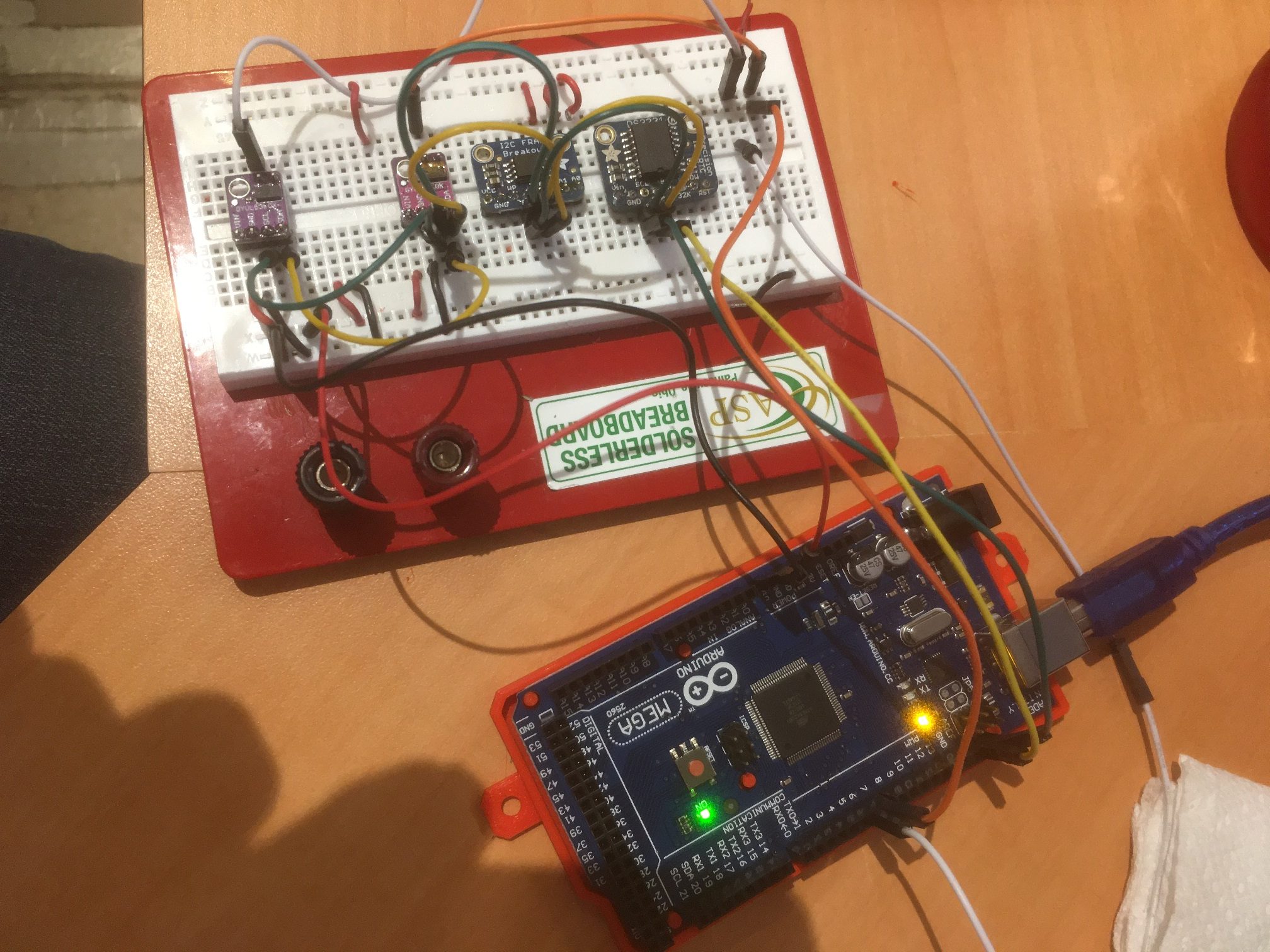
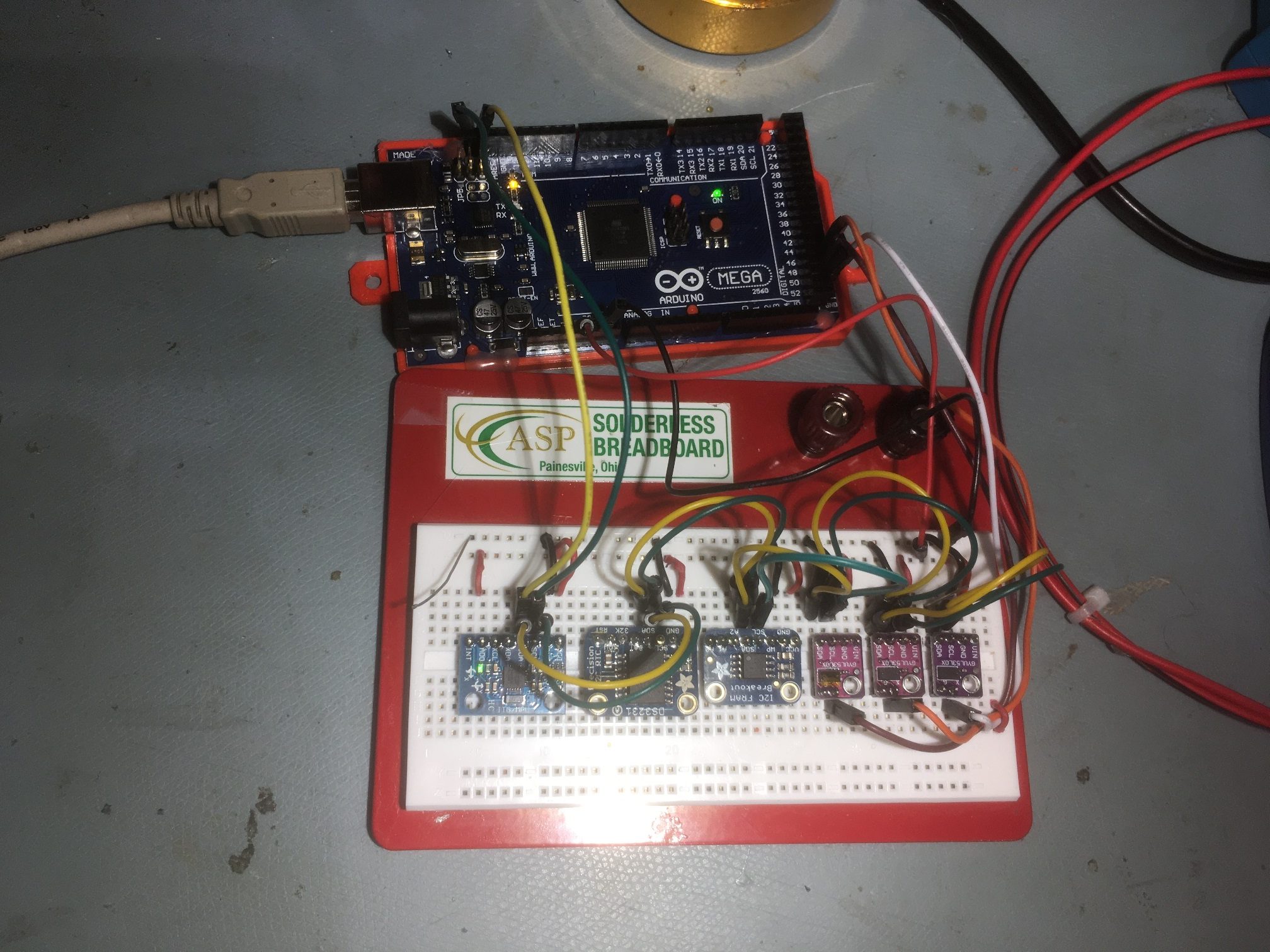
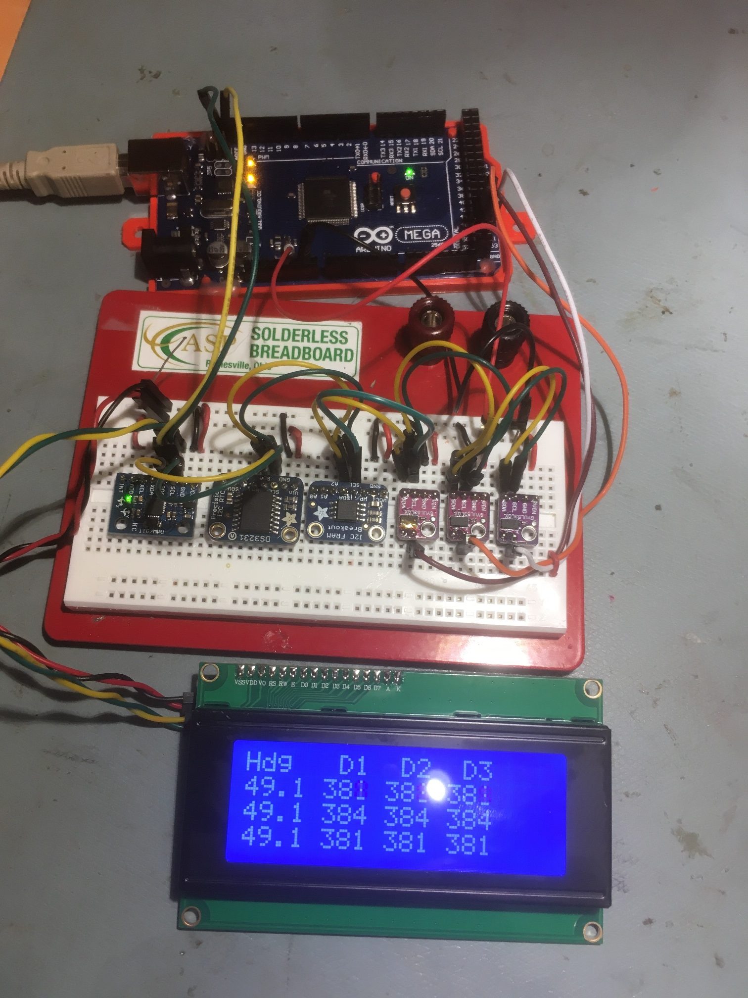
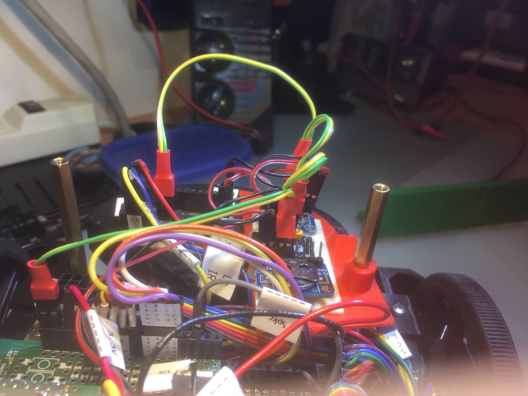
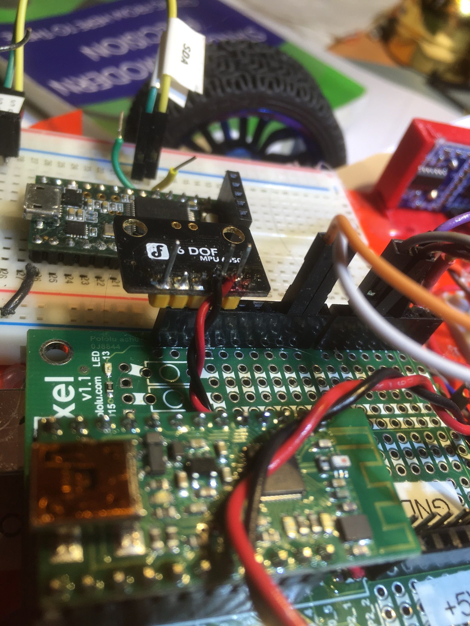
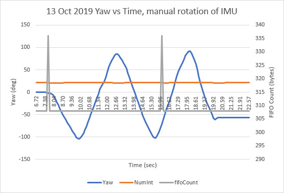
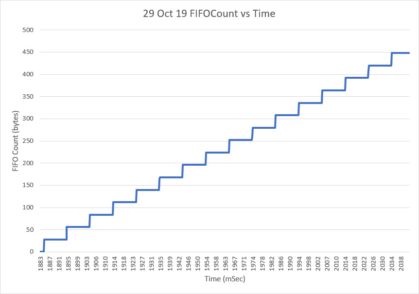
In my autonomous wall-following robot project, I use TIMER5 on the Arduino Mega 2560 to generate an interrupt ever 100 mSec, and update all time-sensitive parameters in the ISR. These include results from all seven VL53L0X ToF distance sensors, the front-mounted LIDAR, and heading information from a MP6050 IMU. This simplifies the software immensely, as now the latest information is available throughout the code, and encapsulates all sensor-related calls to a single routine.

In my initial efforts at turn-rate tuning using the Arduino PID library, I computed the turn rate in the ISR by simply using

This actually worked because, the ISR frequency and the PID::Compute() frequency were more or less the same. However, since the two time intervals are independent of each other there could be a phase shift, which might drift slowly over time. Also, if either timer interval is changed sometime down the road, the system behavior could change dramatically. I thought I had figured out how to handle this issue by moving the turn-rate computation inside the PID::Compute() function block, as shown below

In a typical PID use case, you see code like the following:

After making the above change, I started getting really weird behavior, and all my efforts at PID tuning failed miserably. After a LOT of troubleshooting and head-scratching, I finally figured out what was happening. In the above code configuration, the PID generates a new output value BEFORE the new turn rate is computed, so the PID is always operating on information that is at least 100mSec old – not a good way to run a railroad!

Some of the PID documentation I researched said (or at least implied) that by setting the PID’s sample time to zero using PID::SetSampleTime(0), that Compute() would actually produce a new output value every time it was called. This meant that I could do something like the following:

Great idea, but it didn’t work! After some more troubleshooting and head-scratching, I finally realized that the PID::SetSampleTime() function specifically disallows a value of zero, as it would cause the ‘D’ term to go to infinity – oops! Here’s the relevant code

As can be seen from the above, an argument of zero is simply ignored, and the sample time remains unchanged. When I pointed this out to the developer, he said this was by design, as the ‘ratio’ calculation above would be undefined for an input argument of zero. This is certainly a valid point, but makes it impossible to synch the PID to an external master clock – bummer!

After some more thought, I modified my copy of PID.cpp as follows:

By moving the SampleTime = (unsigned long)NewSampleTime; line out of the ‘if’ block, I can now set the sample time to zero without causing problems with the value of ‘ratio’. Now PID::Compute() will generate a new output value every time it is called, which synchs the PID engine with the program’s master timing source – yay!

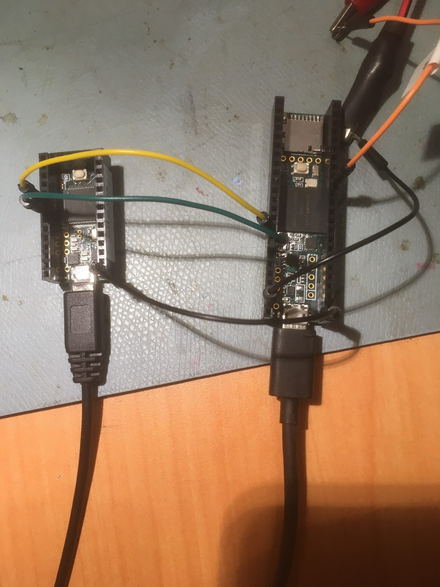
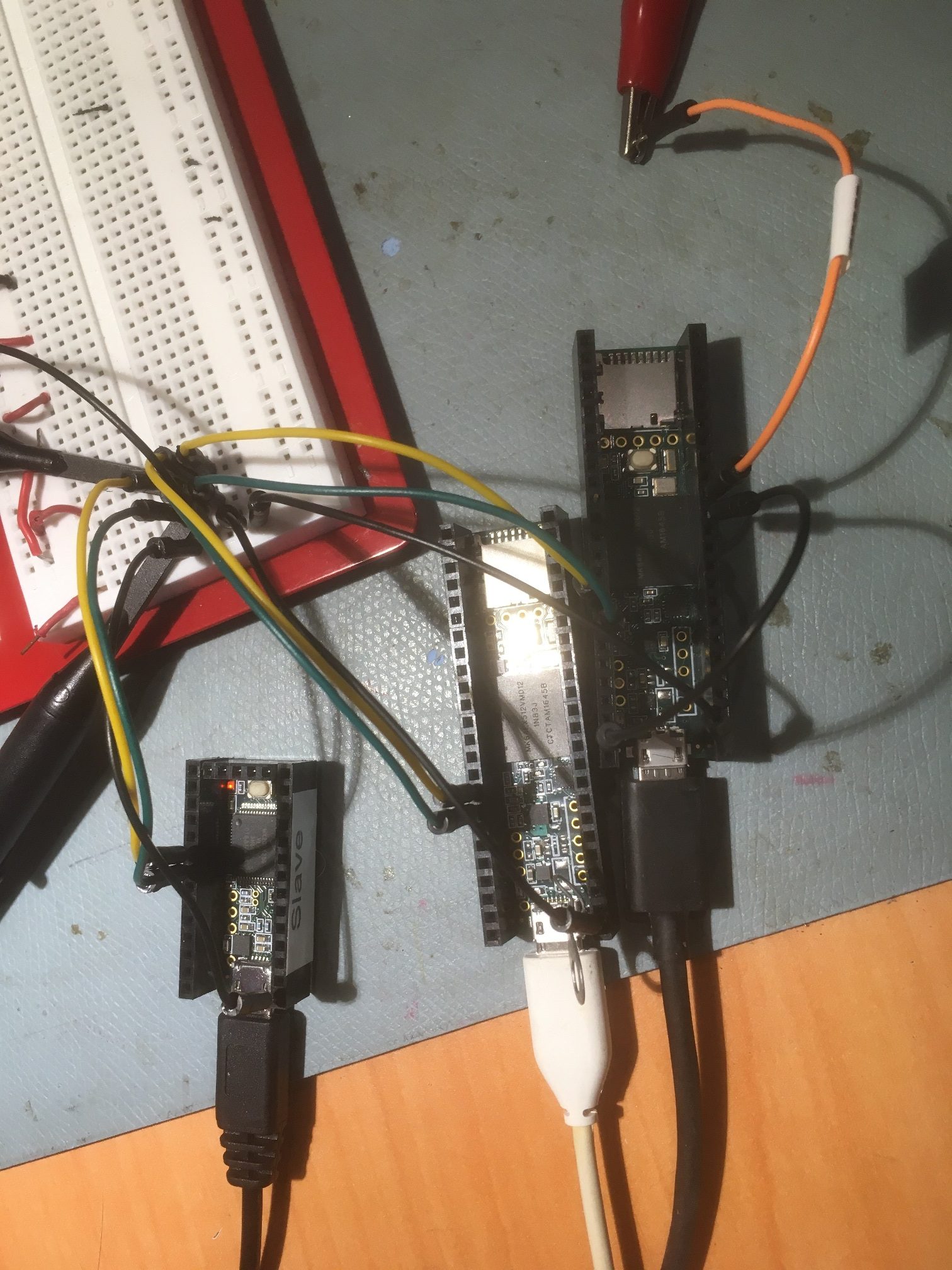
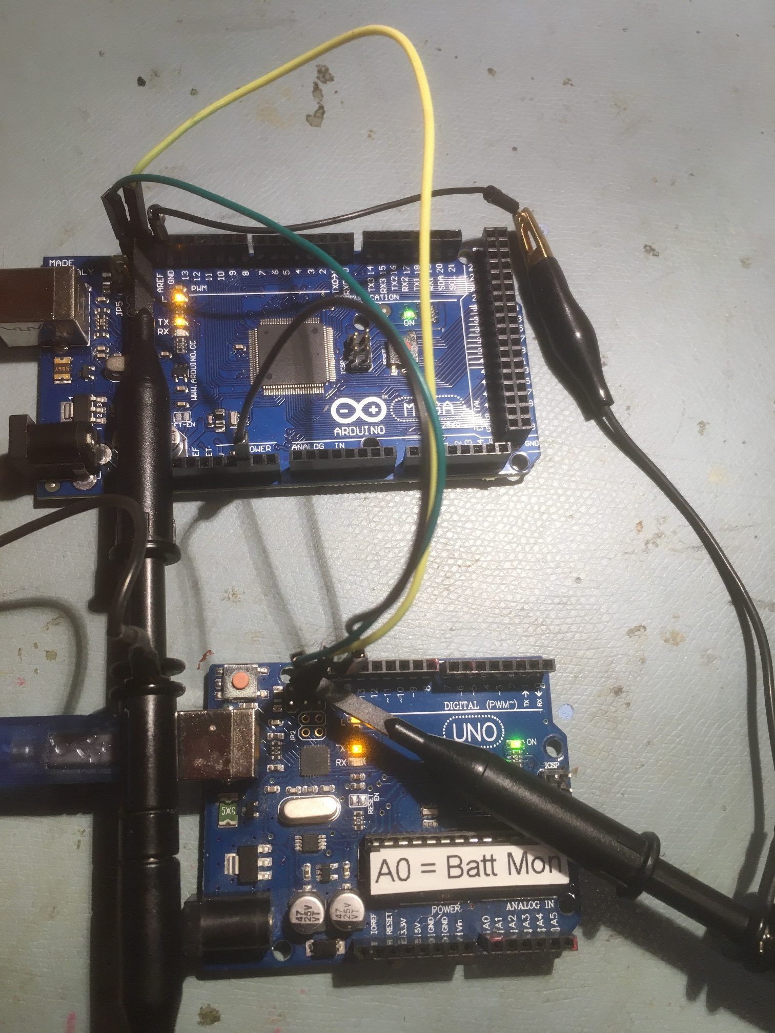
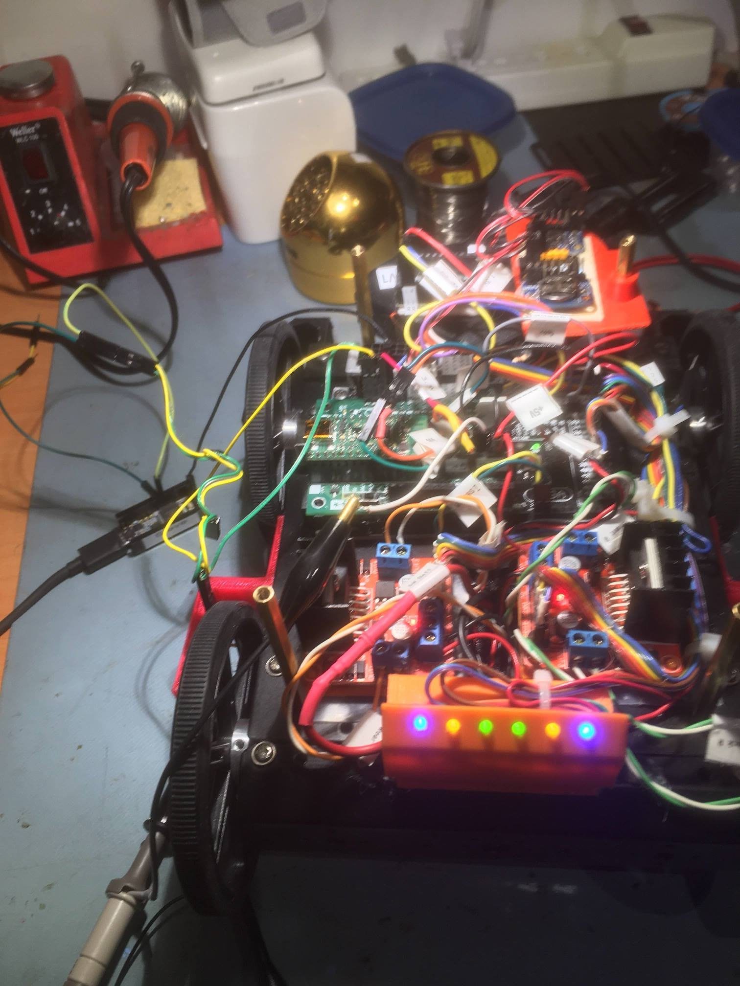
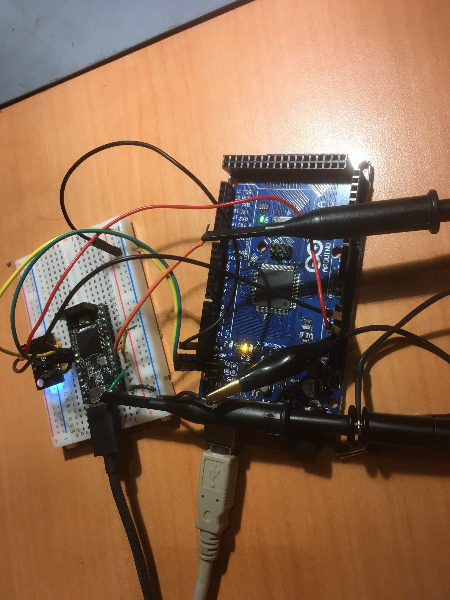
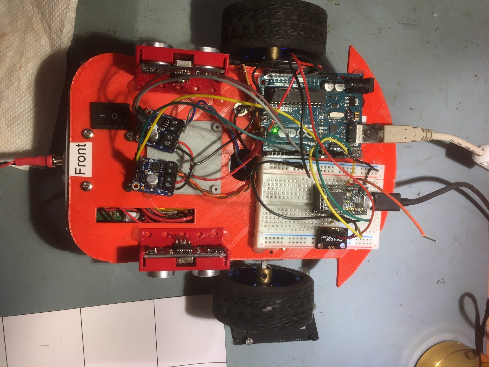
I tried out a slightly modified version of this technique on my small 2-wheel robot. The two-wheeler uses an Arduino Uno instead of a Mega, so I didn’t use a TIMER interrupt. Instead I used the ‘elapsedMillisecond’ library and set up an elapsed time of 100 mSec, and also modified the program to turn indefinitely at the desired turn rate in deg/sec.

I experimented with two different methods for controlling the turn rate – a ‘PWM’ method where the wheel motors are pulsed at full speed for a variable pulse width, and a ‘direct’ method where the wheel motor speeds are varied directly to achieve the desired turn rate. I thought the PWM method might work better on a heavier robot for smaller angle turns as there is quite a bit of inertia to overcome, but the ‘direct’ method might be more accurate.

Here’s the code for the ‘direct’ method, where the wheel speeds are varied with

Here’s the code for the PWM method: the only difference is that is the duration of the pulse that is varied, not the wheel speed.

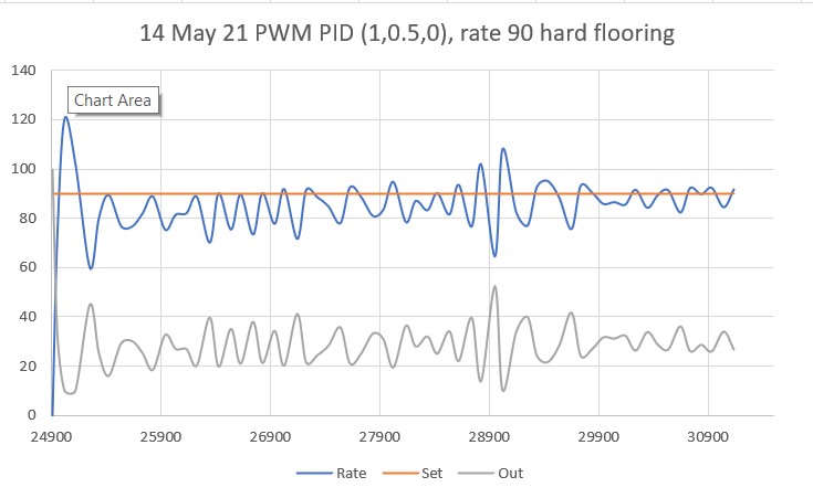
Here’s a short video showing the two-wheel robot doing a spin turn using the PWM technique with a desired turn rate of 90 deg/sec, using PID = (1,0.5,0).

The average turn rate for the entire run was about 85 deg/sec.

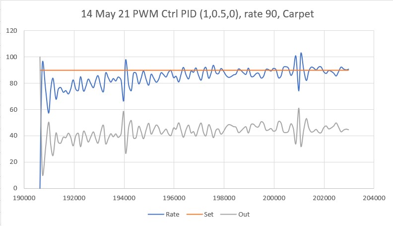
Here’s another run, this time on carpet:

Average turn rate for the entire run was about 85 deg/sec

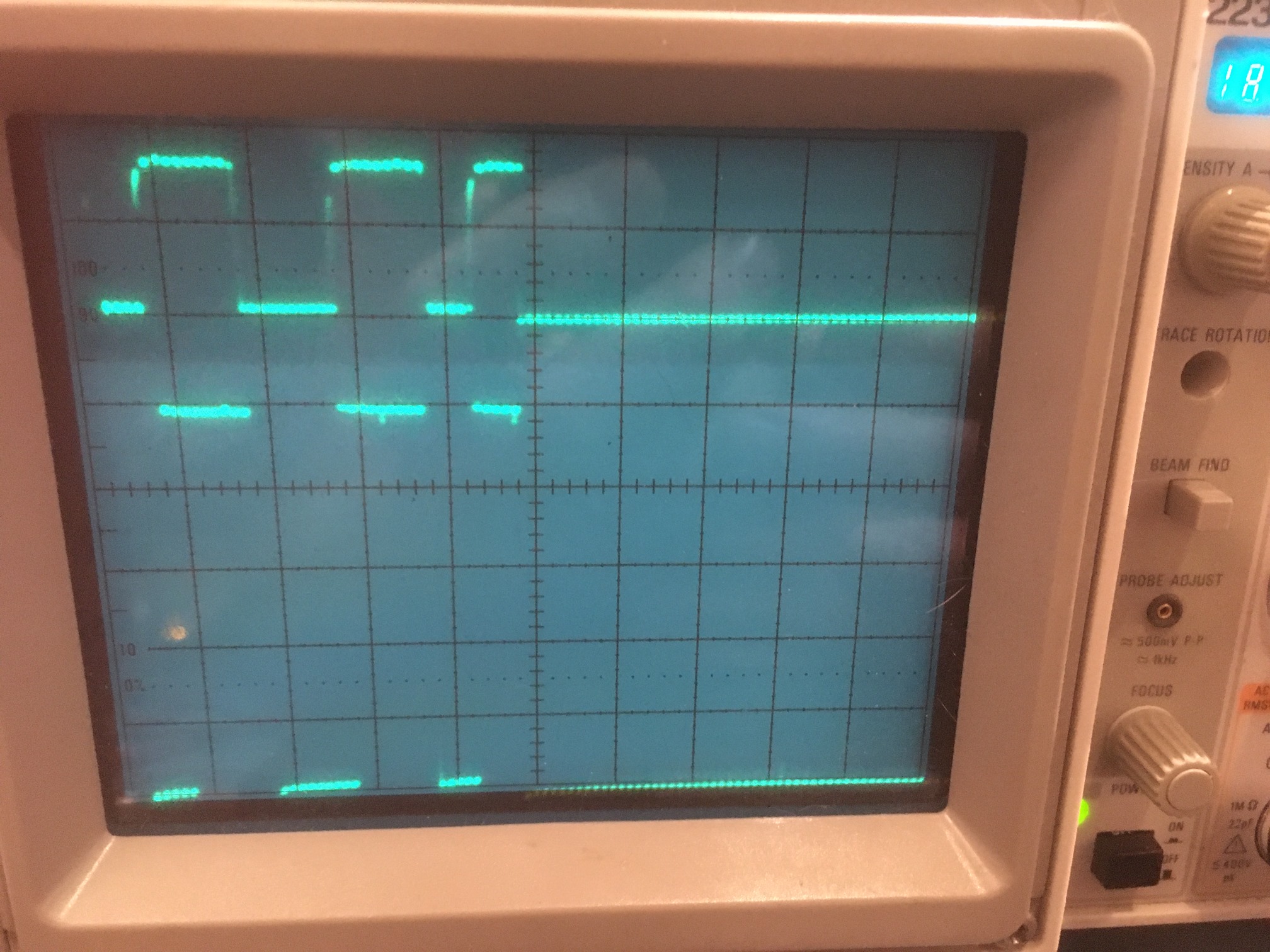
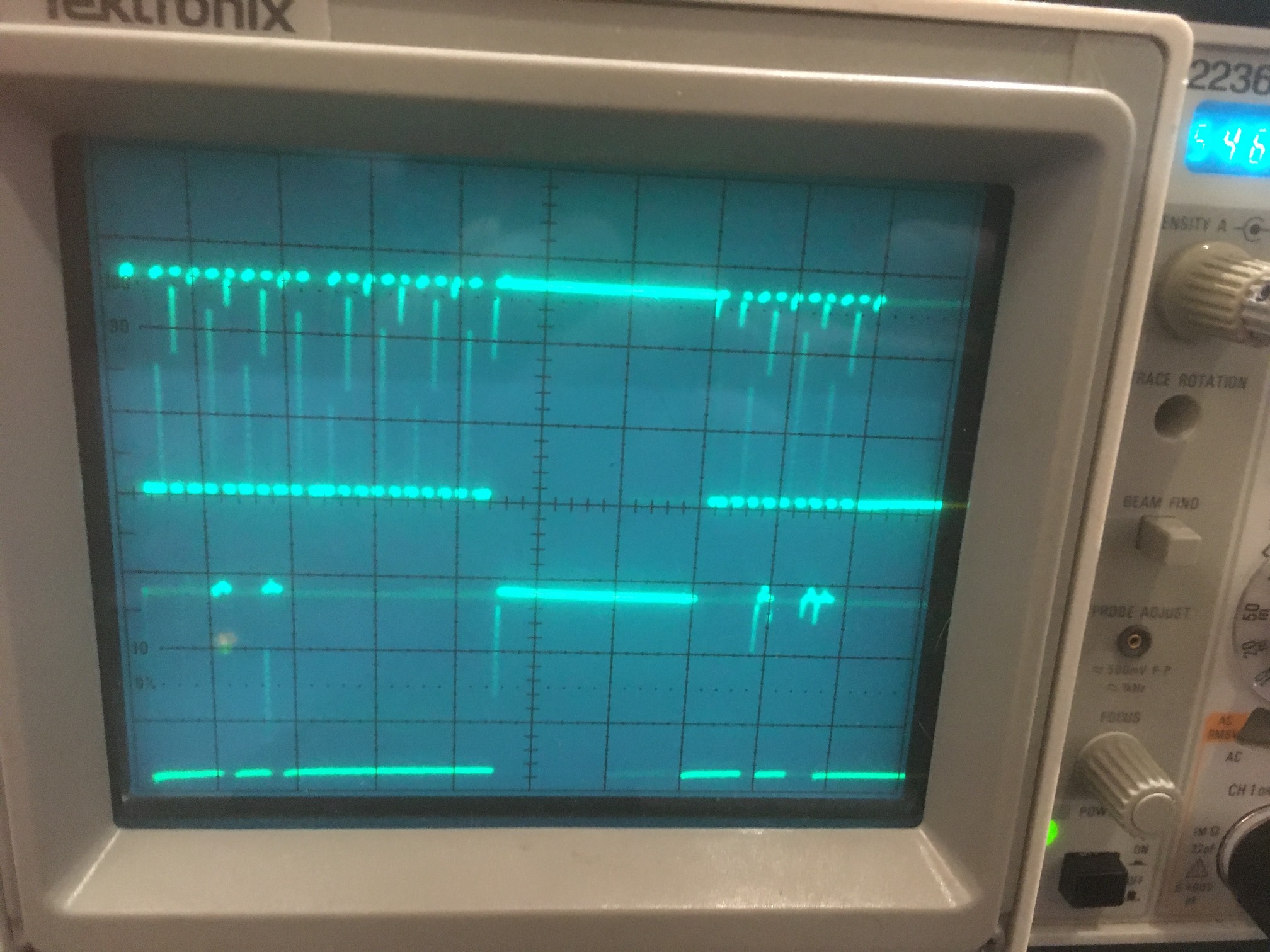
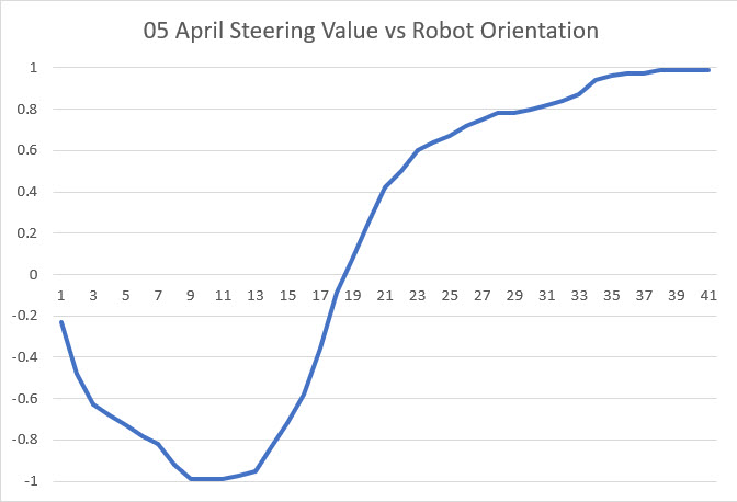
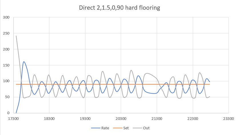
Here’s some data from the ‘direct’ method, on hard flooring
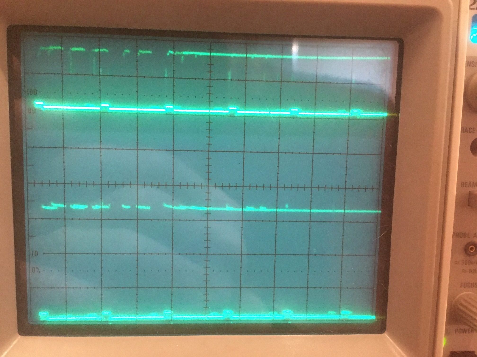
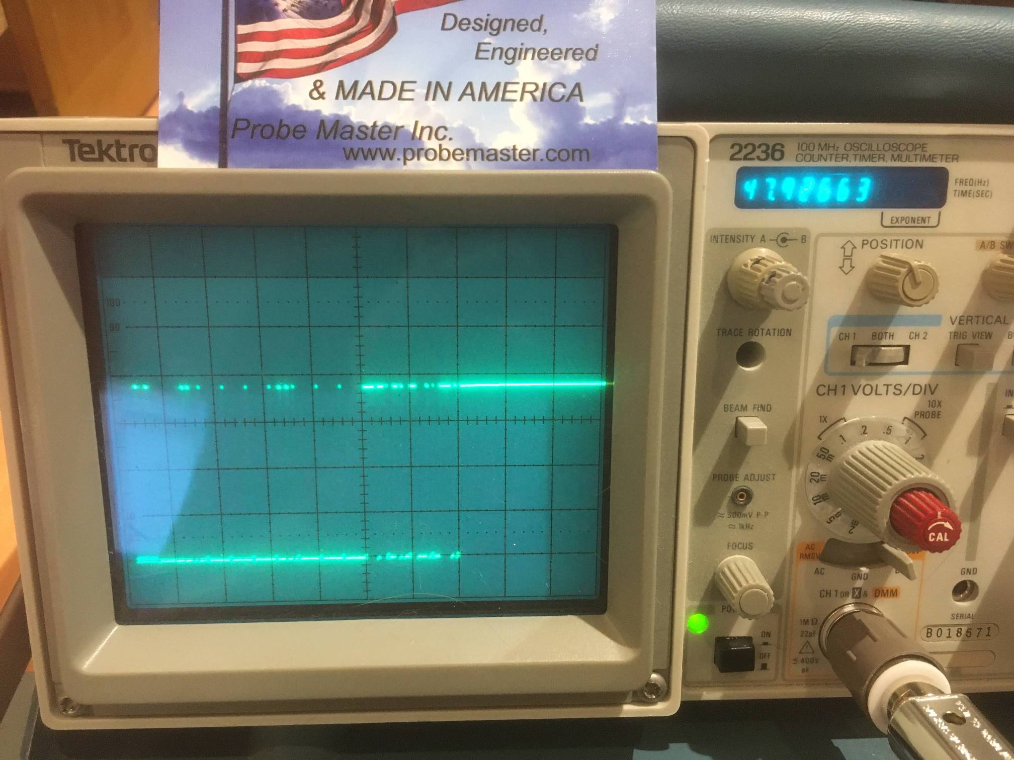
Average turn rate was ~ 85 deg/sec

And on carpet

Average turn rate ~83 deg/sec

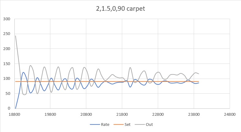
So, it appears that either the PWM or ‘direct’ methods are effective in controlling the turn rate, and I don’t really see any huge difference between them. I guess the PWM method might be a little more effective with the 4-wheel robot caused by the wheels having to slide sideways while turning.

Stay Tuned!

Frank

I2C Hangup bug cured! Miracle of Miracles! Film at 11!

Posted 06 July 2020

Miracle of miracles!  Arduino finally got off their collective asses and decided to do something about the well-known, well-documented, and long-ignored I2C hangup bug.  Thanks to Grey Christoforo of Oxford, England for submitting the pull request that started the ball rolling.  See this  github issue thread for all the gory details.  However, in a bizarre outcome, the implementation of the needed timeouts isn’t implemented by default! You have to modify your code to add a call to a new function, like the following:

Note that you have to explicitly add a timeout value (3000 in my example above) or the timeout feature will still not be enabled! The ‘true’ parameter tells the library to reset the I2C bus if a timeout is detected – surely something you will want to do.

I’m currently working on a ‘before/after’ post to demonstrate that the new timeout feature actually works with real hardware scenarios.  However, due to the intermittent nature of the I2C hangup bug, it takes a while (hours/days) to grind through enough iterations to excite the bug reliably, so it may be a while before I have a good demonstration

One last thing; at some point the examples in C:\Program Files (x86)\Arduino\hardware\arduino\avr\libraries\Wire\examples (on my Win 10 machine) will probably be updated/expanded to show how to properly implement the new timeout feature, but this has not happened yet AFAICT.

The rest of this post describes my attempt to verify that the new timeout feature does, in fact, work as advertised.  The idea is to construct a “before-and-after” demonstration, where the ‘before’ configuration reliably hangs up using the Wire library without the timeout enabled, and an ‘after’ configuration that is identical to the ‘before’ setup except with the timeout enabled.

Before Configuration:

I actually started with a ‘before-before’ configuration using the SBWire library, as I have been working with I2C projects and the SBWire library ever since I gave up on the Arduino Wire library two years ago.  This configuration is patterned after Wall-E2, my current autonomous wall-following robot, which uses an Adafruit RTC, an Adafruit FRAM, a DFRobots MPU6050 IMU, and six VL53L0X time-of-flight proximity sensors (the ToF sensors are managed by a slave Teensy over the I2C bus).  For this test, I arranged all the I2C components on a plug board and connected to them using an Arduino Mega 2560 (the same controller I have on Wall-E2), as shown in the following photo.

From left to right; two VL53L0X ToF modules, FRAM module, DS3231 RTC module, MPU6050 IMU module

The software is a cut down version of the robot software, and in this first test all it does is print out time/date from the RTC and the relative heading value from the IMU.  After almost 13 hours, it was still running fine, as shown below:

So now I have a ‘known good’ (with SBWire) hardware configuration.  The next step is to change the software back from SBWire to Wire without the timeout implemented.  This should fail – the IMU readout should hangup within a few hours as it did before I originally switched to SBWire.

July 08 2020 Update:

After laboriously changing back from SBWire to Wire, I got the configuration shown in the following photo to work properly using the new Wire library without the new timeout feature enabled.

From left to right: MPU6050 IMU, DS3231 RTC, Adafruit I2C FRAM, and 3e VL53L0X ToF proximity sensors, all on the Mega 2560’s I2C bus

I programmed the Mega to access everything but the FRAM 10 times/second, and print out the results on the serial monitor, and then let it run overnight.  When I got up this morning I expected to see that it had hung up after a few hours, but discovered that it was still running fine after eight hours – bummer!  at 10 meas/sec that is 480 min * 60 sec/min * 10 = 288,000 I2C measurement cycles * 5 I2C transactions per cycle = 1,440,000 I2C transactions.  I was bummed out because it will be impossible to verify whether or not the timeout feature actually works if I can’t get a configuration that reliably hangs up. When I came back a few hours later, I saw that the printout to the serial monitor had stopped at around 700 minutes, but this turned out to be the monitor hanging up – not the I2C bus – double bummer.

So, I modified the program to only report results every second instead of 10/second so I won’t run out of serial monitor again, and restarted the ‘before’ configuration.

10 July 2020 Update:

I added the Sunfounder 20 x 4 I2C LCD display to the setup so I could display the IMU heading and proximity sensor distances locally, as shown below

I2C Test setup with Sunfounder 20 x 4 I2C LCD added

After getting this setup running, I was trying to figure out how to definitively demonstrate I2C bus hangups without the Wire library timeout feature (the ‘before’ configuration) and then demonstrate continued operation with timeouts enabled (the ‘after’ configuration).  In an email conversation, Grey Christoforo pointed me to another poster who was doing the same thing, by using an external transistor to short one I2C line to ground under program control, thereby demonstrating that the timeout feature allowed continued operation.  This gave me the idea that manually shorting one of the I2C lines to ground should do the same thing, and would allow me to demonstrate the ‘before’ and ‘after’ configurations.

The following code snippet shows the code necessary to enable the Wire library timeout feature

Although not entirely necessary, this is how I instrumented my code to capture timeout events and display them on my serial monitor

All my other hardware setup code has been removed for clarity.  Notice though, that I tried a number of different timeout values, starting from the default value of 25000 (25 mSec) down to 2000, and then back up to 3000.  At least in my particular configuration, the 1000 value was too small – it caused a timeout flag to be generated on every pass through the loop.  This was an unexpected result, as the SBWire library uses a 100 uSec (i.e. a timeout value of 100) for it’s default timeout value, and this setting has always worked fine in all my I2C projects.

In any case, here’s a short video that demonstrates that the Wire library can now recover from an I2C bus traffic interruption via the use of the new timeout feature.


Stay tuned!

I2C between an Arduino Mega and a Teensy 3.x

posted 18 March 2020

This post describes my efforts to troubleshoot an I2C communications problem between an Arduino Mega control board and a Teensy 3.2 IR beam demodulation module.

Background:

My Wall-E2 autonomous wall-following robot homes in on a modulated IR beacon to connect to a charging station. The IR beacon modulation is decoded by a dedicated Teensy 3.2 and provides left/right and combined steering values to an Arduino Mega main controller over an I2C link.

During my recent work to update the robot after some enhancements, I discovered that the main controller was no longer receiving steering information from the Teensy, even though both seemed to be operating properly.  Initial efforts to troubleshoot the problem did not bear fruit, so I was forced to back up and start over from scratch.

Troubleshooting:

Initially I thought the problem was a loose connection, as the system was working before.  However, I am now pretty sure that I have eliminated all the obvious culprits, so I am left with the non-obvious ones.

To start with, I resurrected an old example project to demonstrate I2C master/slave operation between two Teensy modules.

Teensy 3.2 Slave (left) and Teensy 3.5 Master (right)

Here’s the Teensy ‘Master’ code:

And the Teensy ‘Slave’ code:

With this configuration I got the following output:

Master:

Slave:

So this seems to be working OK.

Then I added in a third Teensy module (T3.5) running my newly developed I2C-Sniffer code, so that I could ‘sniff’ the I2C traffic between the two Teensy’s.  This will give me a ‘known-good’ baseline for when I move back to the non-working Arduino Mega Master and  Teensy Slave condition that is causing me problems.

Teensy 3.2 Slave (left), Teensy 3.5 I2C Sniffer (middle), Teensy 3.5 Master (right)

Here’s the Teensy ‘Sniffer’ code:

With this setup with the master sending data to the slave, I got the following outputs:

Master

Slave:

I2C Sniffer:

In the other direction, with the slave sending data to the master, I got the following:

Slave:

Master:

I2C Sniffer:

Where the HEX sequence 4B D8 A9 AD converted to a IEEE float = 2.83984e+07

So, the Teensy-to-Teensy I2C connection is clearly working in both directions, and the Teensy I2C Sniffer is successfully capturing and decoding the I2C traffic between the two modules – cool!

So, the next step is to replace the ‘Master’ Teensy with an Arduino Mega and repeat the process.  Hopefully this will allow me to figure out why the slave-to-master data transfer isn’t working

21 March 2020 Update:

Based on the above results, I formed a hypothesis that the problem with sending I2C data from a Teensy slave to an Arduino Mega master might be due to the Mega not being able to properly interpret 0-3.3V transitions from the Teensy.  So, I decided to construct a low-to-high level converter to make sure that SDA data from the Teensy was presented to the Mega as 0-5V transitions rather than the Teensy’s ‘raw’ 0-3.3V ones.  To do this I used the circuit shown below, except with a 1K instead of 10K resistor for R2 to clean up the transitions at 100KHz.

Bidirectional 3.3-5V level shifter using 2N7000 MosFet

Here’s a scope photo of the 3.3V input to and the 5V output from the 2N7000-based level shifter. The top trace is the Teensy 0-3.3V output, and the bottom trace is the 0-5V level-shifted version.  Both traces are 1V/cm, and the horizontal time scale is 20 uSec/cm.

Teensy slave, Mega master: Top: 0-3.3V input. Bottom: 0-5V output. Both traces are 1V/cm vertical, 20 uSec cm horizontally

To verify that the above circuit worked properly, I used it in the SDA line (the SCL line doesn’t require any level shifting as it is from the 5V Mega to the 3.3V Teensy) with a Teensy slave and a Teensy master.  This is OK, as Teensy 3.x’s can handle 5V inputs, and it worked properly in both directions.  Here’s a shot of the SDA line

Teensy slave, Teensy master: Top: 0-3.3V input. Bottom: 0-5V output. Both traces are 1V/cm vertical, 20 uSec cm horizontally

However, after replacing the Teensy master with the Mega one, I had the same problem as before – I can successfully transfer data from Mega master to Teensy slave, but not in the other direction. There is still a problem somewhere, and I no longer think it’s due to level-shifting problems.  From the above scope photos, it is clear that only a few bytes are transmitted by the Teensy slave each time it services the OnRequest() interrupt, while that same function transmits MUCH more data when servicing the same request from the Teensy 3.5 master.

Stay tuned!

23 March 2020 Update:

OK, back to the basics:  I downloaded the code for a very basic Arduino-Arduino I2C tutorial, and verified that it worked OK.  I also took a scope shot of SDA/SCL activity during the two-way data transfers, as shown below:

Basic Arduino-Arduino tutorial layout

I2C line activity for the ‘Basic Arduino – Arduino I2C Tutorial’

So now that I have a working baseline for the Arduino-Arduino I2C case, I plan to incrementally modify it toward duplicating the non-working Arduino-Arduino I2C case until it breaks, and then I’ll know that the last incremental modification is the culprit. At the moment, I’m leaning toward the use of the I2CDev & SBWIRE libraries as they are the only significant difference between the working and non-working setups.  We’ll see….

24 March 2020 Update:

I created a new Arduino project called ‘I2C_Master_Tut_Mod1’ initially identical to ‘I2C_Master_Tutorial’ and verified that it worked properly with the unmodified ‘I2C_Slave_Tutorial’ project, and then started modifying it.

  • Added #include <PrintEx.h> //allows printf-style printout syntax
    StreamEx mySerial = Serial; //added 03/18/18 for printf-style printing, and changed all occurrences of ‘Serial’ to ‘mySerial’ and modified print statements to ‘printf’ format. All worked fine.
  • Added #include <I2C_Anything.h> and changed loop() to write a float value to the slave.  However, this caused a compile error.  When I started tracking it down I realized that I had previously modified ‘I2C_Anything.h’ to #include SBWIRE.h rather than the original #include Wire.h.  So, this could be the culprit, assuming that there is something about SBWIRE that causes Arduino I2C slaves to misbehave.
  • Copied I2C_Anything.h/cpp from the Libraries folder to my new ‘I2C_Master_Tut_Mod1’ folder, and un-modified it to reference back Wire.h vs SBWIRE.h.

25 March 2020 Update:

As it turns out, I was never able to get the ‘I2C_Master_Tut_Mod1’ project working with #include <I2C_Anything.h> , no matter what I did, including copying the #include <I2C_Anything.h> to the local folder and including it as a resource int the VS2019 project, build cleans, removing the _vm folder created by Visual Micro, etc.  To make it even stranger, I created a new Arduino project in VS2019 called ‘I2C_Master_Tut_Mod2’, copied the ‘I2C_Anything.h’ file to the local folder, and it compiles without error!  So now I have two almost completely identical Arduino projects, one of which compiles fine and the other of which blows a bunch of errors about twi.c.  I’m currently working with Tim Leek at VisualMicro to sort out what I did wrong.

27 March 2020 Update:

Ok, I now have the Arduino Mega master to Arduino Uno slave setup working, with I2C_Anything.  I can transfer a float value in either direction with no problem. The master and slave code sets and the corresponding outputs are shown below.

Master Sketch:

Slave Sketch:

Master  & Slave Output:

So now I have a working Arduino-Arduino I2C master/slave setup, using I2C_Anything.h to transfer float values back and forth, and a working Teensy-Teensy I2C master/slave setup, using I2C_Anything.h to transfer float values back and forth. 

The next step was to replace the Arduino Uno I2C slave with the Teensy 3.2 I2C slave and see if I can get that combination working.  This turned out to be surprisingly easy – basically plug-and-pray (oops, I meant ‘play’).

Now that I have a simple Arduiono Mega Master – Teensy 3.2 Slave setup working, I can start to explore why my 4WD robot setup doesn’t work.  Some possibilities:

  • It could be that the SBWire version of the Wire library has some hidden bugs in the slave-related code.  The SBWire library eliminates the well-known and well-hated ‘hang’ bug in the Arduino wire library.
  • It could be that some other library I am using, like the RTC library or the Adafruit FRAM library is interfering with the Arduino-Teensy interrupts needed for master-slave communication.
  • It could be that the IR demod program running on the slave Teensy is somehow interfering with master-slave communications (this is very unlikely as this same program had been working flawlessly for several months).
  • Something else…

To start with, I copied the current ‘I2C_Master_Tut2’ VS2019 project to a new one – ‘I2C_Master_Tut3’ before making any modifications.  I plan to keep a ‘breadcrumb trail’ of incrementally modified projects so that I can go backwards in case I get lost at some point (and, in my fairly long 50+ years as a practicing engineer, I have learned that ‘getting lost’ is part and parcel of any non-trivial troubleshooting project).

Once I verified that ‘Tut3’ properly communicated with the Teensy slave, I started making modifications.

  • Replaced #include <Wire.h> with #include SBWire.h.  This failed in compile with a linker error, but succeeded after I did a ‘Build -> Clean’.  After uploading the new ‘Tut3’ version to the Mega, I found that master-slave communications still worked properly.  This is actually a welcome development, as that now eliminates SBWire as the culprit for lost Mega-Teensy I2C capability on the robot.
  • Replaced ‘#include “SBWire” with #include “MPU6050_6Axis_MotionApps_V6_12.h” and include “I2Cdev.h” (this includes SBWire.h).  These two libraries are required for interfacing to the MPU6050 IMU module.

29 March 2020 Update:

So I created a new copy of the I2C master, ‘I2C_Master_Tut4’ and started adding things from the original non-working robot program.

  • Added all the remaining #include’s.  Still works fine with the Teensy 3.2 slave
  • Added all the #defines. Still works fine
  • Added all the IRHOMING parameters.  OK
  • Added all ENUMs, Battery constants, distance measurement support constants & array declarations,  motor parameters, wheel direction constants and variables, and heading based turn parameters.  No problem
  • Added pin assignments.  No problem.
  • Added all the other pre-setup stuff.  No problem
  • Added ‘ Serial1.begin(9600); //03/04/16 bugfix’. This isn’t actually used anymore in the robot project, but it is there, so it could be the culprit.  Nope –  master/slave comms still OK.
  • Added RTC initialization and  support function.  Still no problem
  • Added FRAM initialization.  No problem.
  • Added MPU6050 initialization.  No problem
  • Added PID distance array and incremental variance initialization.  No problem
  • Added I/O pin initialization.  No problem
  • Added the rest of Setup(), and all the support functions required for the POST check to run.  Compiles and runs fine.  Of course, no peripherals are attached, so not much happens.

At this point I have all the pre-setup and setup code incorporated into the master/slave example, and everything is still happily plugging away.  So obviously the culprit hasn’t yet been identified.  However, before going any farther, I think I’ll drop ‘Tut4’ into the safe-deposit box and create a ‘Tut5’ to continue on into the loop() function.

OK, so I have a ‘Tut5’ project now, with everything up to loop() incorporated from the ‘FourWD_WallE2_V2’ robot project.  Now the question is, ‘What next?’.  I need to figure out what is causing I2C comms between the Mega master and the Teensy 3.2 slave to fail, so I need a way to faithfully replicate/simulate/emulate the actual robot code for this function.

The current robot algorithm as pertaining to the Teensy IR Demod module

  • Each time through the loop, the current operating mode is determined.
    • If IsIRBeamAvail() returns TRUE, the IR HOMING mode is activated
      • IsIRBeamAvail() gets three float values from the Teensy 3.2, and returns TRUE if the total of the first two values (Fin1 & Fin2) is above a set threshold.  It is this function that is failing to communicate with the Teensy.  More specifically, it is this function that is not successfully acquiring the three float values, and subsequently always returns FALSE.

So, it may be that all I have to do is to call IsIRBeamAvail() by itself, and modify the slave code to send back three floats as expected.  If this works, then I’ll have to start suspecting the robot’s Teensy or the I2C wiring, or something else entirely.

2 April 2020 Update:

After some additional fumbling around with I2C_Anything and the PrintEx library printf() formats, I now have a working ‘IsIRBeamAvail()’ function in ‘Tut5’, as follows:

Which, when connected to my basic  Teensy 3.2 I2C slave program produces the following (correct) output:

At this point we have a working robot code emulation that communicates successfully with a basic Teensy 3.2 slave.  So, the available culprits have been reduced significantly to

  • Something about the Teensy IR demod code
  • The I2C Wiring
  • A hardware problem at either the robot’s Mega controller or the robot’s Teensy 3.2 controller
  • Something else.

For the next step, I modified the Teensy IR Demod code to emulate the IR detector response and loaded this code into the Teensy 3.2 slave connected to the Mega master.  After some initial mis-steps, it started working nicely, with the following (correct) output from the Mega master:

So this eliminates the ‘Something about the Teensy IR demod code’ possibility from the above list.

Next, I replaced the direct SCL/SDA jumpers with the daisy-chain wiring from the robot, and miracle of miracles, I2C comms failed – YAY!!.  Now hopefully I can figure out (and fix) the problem.

  • First, I un-replaced the daisy-chain wiring to confirm that I2C comms were still working, and they were.
  • Unplugged the daisy-chain from the FRAM, 6050IMU, and RTC modules – now working OK
  • Plugged back in to FRAM unit (now have FRAM and Teensy 3.2 in chain)- – still OK
  • Plugged back in to 6050 IMU (now have IMU, FRAM, and Teensy 3.2 in chain)- failed
  • Plugged back in to RTC (now have RTC, FRAM, and Teensy 3.2 in chain)- failed

3 April 2020 Update:

The next step in the saga was to load the ‘Tut5’ code onto the robot’s Mega 2560 controller, with the slave code still running on the original (off-robot) Teensy 3.2.  Setting things up in this fashion allowed the sensors to receive power from the robot’s Mega controller as in normal operation.

In the photo above, the Teensy 3.2 slave is shown to the left of the robot.  The I2C ‘daisy-chain’ cable starts at the Mega controller (just to the right of the front left wheel), and goes through three ‘hops’ to the Teensy. With this setup, the I2C comms code still ran fine, with direct I2C jumper wires or with the daisy-chain wiring setup (with no connections to the other I2C sensors) as shown above.

The next step was to connect the robot’s Mega controller to the robot’s Teensy 3.2 running the unmodified IR Demodulation code, with the I2C daisy-chain cable, but without anything else connected.  This actually worked!  So now I have a working robot system again, so something about the connections with the other sensors must be killing the I2C link to the Teensy.  Here’s a scope photo of the SDA line showing the data activity. The vertical scale is 1V/cm, showing the HIGH value is about 3.8V, so the Mega must be comfortable with that value as a HIGH logic level

In the above photo, notice the business card for Probe Master, Inc (www.probemaster.com).  These folks were kind enough to replace my ten year old scope probe with a new upgraded version at no cost – thank you Probe Master!

At this point I have the ‘Tut5’ program running on the Mega, and the unmodified IR Demod code running on the robot’s Teensy 3.2, and the Mega appears to be acquiring valid demod data from the Teensy.  To further validate the data, I fired up my charging station with it’s square-wave modulated IR beam, and was pleased to see that the acquired data from the Teensy varied appropriately as I manually rotated the robot, as shown in the following Excel chart.

So, after all this work, the whole thing came down to a bad I2C ‘daisy-chain’ cable. This particular cable has been on the robot for a while, and was the soldering graduation exercise of my grandson Danny  when he was here a couple of summers ago.  It wasn’t the best job I’ve ever seen, but it was pretty good for a 15 year old ;-).  In any case, I took the opportunity to build a new cable with smaller diameter wire so things would fit a little bit better into the Pololu pins, sockets, and 2-pin header sleeves as shown in the following photo.

New I2C ‘daisy-chain’ cable.  Run starts from the Mega connector at bottom left, then to the RTC, IMU and FRAM modules in that order, then last to the Teensy 3.2 IR Demod module.

05 April 2020 Epilogue:

Well, there was one last ‘gotcha’ in all this.  When I loaded the original ‘FourWD-WallE2_V2.ino’ program back onto the Mega, it still refused to acquire valid data from the Teensy IR Demod module.  So, I compared the ‘Tut5’ code to the ‘_V2’ code, and noticed three significant differences:

  • In the ‘_V2’ code, the ‘Fin1/2’ variables had at some time been changed from ‘long’ to ‘int’. While this sounds reasonable, it isn’t – because a Teensy ‘int’ is 4 bytes – the same as a Mega ‘long’.
  • In the ‘_V2’ code, the  Wire.requestFrom() call asks for 32 bytes, but the Teensy only sends 12.
  • In the ‘_V2’ code there is a loop that waits for either a timeout or receiving an entire 32-byte buffer from the Teensy.  Apparently the Teensy (and/or the Mega) is slow enough so that Wire.Available() never reports a non-zero buffer size, so the loop times out.

Replacing the line

with the line

did the trick, but I have no idea why.

Replacing the debug printout lines

with the line

Produced lines like this one from the ‘_V2’ program

Which appear to be the correct values for the given robot orientation with respect to the charging station.

With no other changed except removing power from the charging station, the output became

showing definitively that the ‘_V2’ program correctly identified and decoded the square-wave modulated IR beam.

So, after a two-week off-road trip to I2C comms hell and back, I think I finally have that particular issue put to bed.  It wasn’t exactly what I wanted to do, but it was at least interesting, and more important – consumed a lot of coronavirus quarantine time ;-).

Stay tuned!

Frank

Wall tracking: finding the heading parallel to the nearest wall

Posted 14 February 2020,

Happy (American) Valentines Day! In my last post, I described my plan to use Wall-E2’s new relative heading super power to find the relative heading parallel to the nearest wall.  I ended that post with “…and not all that hard to program, either”.  Well, this turned out to be a bit of an exaggeration as things weren’t quite as easy as I first thought; the interaction of the physics of the robot and the time scales associated with ping measurements complicated things a bit.

Background:

For some time now I have been working on ways to enhance Wall-E2’s autonomous wall-tracking ability.  Wall-E2 can track walls fairly well, but lacks the ability to track a wall at a specified stand-off distance.  Currently, tracking occurs at whatever distance Wall-E2 first detects the nearest wall. While this isn’t terrible, I wanted to do better.

Unfortunately, the way in which the measured ‘ping’ distance to the nearest wall interacts with the relative orientation of the robot with respect to that wall makes it almost impossible to determine the actual offset distance, and therefore how to determine what to do to maintain a constant offset distance.  As shown in the following diagram, when the robot makes a turn, the measured distance to the wall will change just due to the orientation change, without the robot’s actual offset distance changing at all.

Without having some idea of the angle theta in the above diagram, making a judgement of where the robot is relative to the target offset distance is difficult, if not impossible.   This situation was the impetus for adding the MPU6050 Inertial Measurement Unit (IMU) to Wall-E2’s list of super powers. The general idea was that knowledge of relative headings would allow Wall-E2 to make accurate heading-controlled turns without relying solely on timing.  After a lot of work to eliminate RFI/EMI problems associated with the Pololu metal-geared motors on Wall-E2, I’m happy to say that the MPU6050 is now quite stable, and making turns of just a few degrees is quite possible.

However, acquiring and then maintaining a particular offset distance from the nearest wall is still not straightforward.  Back in early December last year I demonstrated the ability to acquire and then maintain a constant offset distance, but only if the robot started out reasonably parallel to the wall.  If the robot was oriented toward or away from the wall by more than a few degrees, it would not work.  So I needed to find a way to first orient the robot parallel to the nearest wall at any distance, so that my current acquisition & tracking algorithm would work successfully.

The basic idea behind finding the parallel heading is that when the robot is turned through a forward arc and the measured ‘ping’ distance decreases and then starts increasing, the robot’s relative heading at this inflection point is the desired parallel heading.   If the distance instead starts increasing, then the robot started out either parallel to or facing away from the wall.  In either case, reversing the turn back toward the wall will cause the measured distance to decrease to a minimum and then increase again.  As in the first case the heading at the point at which the measured distance starts to increase is the desired parallel heading.

Although the basic idea as described above is very straightforward, as usual there are some ‘gotchas’ in the actual implementation:

In order to minimize heading overshoot due to the robot’s mass and angular momentum,  the parallel heading search turns must be performed at lower-than-normal speeds.  After some experimentation I settled on a turn rate of about 60 deg/sec.  With the robot starting with an angle-in orientation of about 30 deg, this means that it takes about 1 second to sweep through to an angle-out orientation of about 30 deg.  With the Arduino UNO setup I’m using for the tests, I was getting distance measurements about every 30-50 mSec, so about 33 to 20 measurements/sec, or around 2-3 measurements/degree.

The lower turn rate significantly reduces the rate at which the ‘ping’ distance changes per unit time, making it much harder to detect the distance inflection point.  In effect, the lower turn rate flattens the ‘distance/degree’ slope, making inflection point detection more difficult.  At 20-30 measurements/degree and only a few cm change from max on one side to max on the other, there are a lot of identical measurements returned.

My initial cut at addressing the the above issue was to space the ping measurements further apart in time, thereby increasing the ‘distance/degree’ slope. After trying this (using a ‘elapsedMillisec’ variable) I realized that an equivalent method would be to simply increase the size of the inflection detection window (the number of times the ping measurement must be on the ‘other side’ of the inflection point in order to qualify as a valid inflection). After some experimentation, I arrived at a value of 20.

For some reason, it was much easier to find a good parallel heading value if the robot started out pointed toward the near wall. If it started out pointed away from the wall, the robot often stopped well short of or well after the actual parallel heading.  Eventually I developed a 4-turn process for this case to really nail down the parallel heading.  Here are some short videos demonstrating the algorithm.

Now that I can reliably determine the relative heading that orients the robot parallel to the nearest wall, I should be able to marry this capability with my already-developed algorithm for acquiring and maintaining a specific offset distance.

20 February 2020 Update:

So I combined the ‘find parallel heading’ feature with my already-existing angle-based tracking algorithm, and this worked fairly well.  Here’s a short video demonstrating the technique:

In the above video, the blue painter’s tape strips are marked every 10 cm, with a double-width mark at 30 cm (the desired offset distance). As the video shows, the robot first determines an approximate parallel heading, and from there starts the normal angle-based tracking algorithm.

Next, I tried an ‘enhancement’ to the above by having the robot move toward the wall on a 30-45 deg ‘cut’ from the parallel heading, and then turning back to parallel at the desired offset distance.  As the following video shows, this didn’t turn out so well.  If the robot doesn’t start out exactly parallel, then the ‘cut’ is either too steep or too shallow, resulting in a too-early or too-late turn back to the parallel heading.

So it looks like the ‘find parallel then start tracking’ approach works pretty well, but the ‘find parallel then drive to offset on a cut then back to parallel’ approach hasn’t been very successful.

27 February 2020 Update

After thinking about the difficulties I was encountering with my ‘FindParallel’ algorithm, I realized that the reason the robot was often overshooting the parallel orientation was due to small aberrations in ‘ping’ distance measurements that caused the ‘hit counter’ to reset to zero in the middle of an otherwise perfect arc of distance values.  The ‘hit counter’ is incremented each time the newest ‘ping’ distance measurement trends along the same line, and is reset to zero whenever the newest ping measurement breaks the trend. When the hit counter exceeds a preset level, the parallel condition is considered to be detected.  I thought I might be able to improve performance by making the algorithm a little more tolerant of such aberrations.  So, rather than having the ‘hit counter’ reset to zero, I changed the algorithm to decrement by a set amount rather than reset it to zero.  This markedly improved performance, as shown in the following videos.

There are four sections in the above video.  In the first clip, the robot starts out pointed away from the wall and outside the desired 30 cm offset. The ‘FindParallel’ algorithm executes, and then approaches and then tracks the wall at the desired 30 cm offset.  The next three clips show the same situation, except starting outside the 30 cm offset and pointed toward the wall, and then from inside the 30 cm offset, pointed away from and toward the wall.  In each case, the robot successfully acquires a reasonably parallel heading and then acquires and tracks the 30 cm offset distance.

Stay tuned!

Frank


IMU Motor Noise Troubleshooting, Part III

Posted 19 January 2020

In Part II of this saga, I described my continuing efforts to track down and fix the problem of intermittent failures associated with the MPU6050 IMU on my robot.  The MPU6050 IMU is required for the ability to make precise heading-based turns, which is in turn required to track walls at a designated stand-off distance.

This post summarizes the work to date and suggests new avenues of investigation for fully addressing the motor noise issue.

Summary of work to date:

  •  July 2019: First started working with heading-based turns, and first noticed the motor noise problem.  Basically the problem presented itself as frequent, abrupt, and wildly divergent heading readings when the motors were running, but perfectly stable readings when the motors are not running.  See this post for the details.
  • October 2019: Successfully demonstrated polling-based (vs interrupt-based) MPU6050 IMU management. This development meant that I could acquire yaw (heading) values on an as-needed basis rather than at a 20 or 200Hz rate, throwing away 99% of the results.  This was demonstrated in this post.
  • November 2019: Made another run at solving the motor noise problem using a home-brew optical isolator and  a 2-stage power filter.  After a LOT of work, I wound up discovering that most (but not all!) of the problem could be addressed with proper RF bypassing at the terminals of the metal-geared Pololu motors I was using.  See this post for the details.
  • Early December 2019:  Demonstrated heading-based wall offset tracking using my 2-motor robot, with RF bypassing installed on both Pololu metal gear motors.  No IMU failures were noticed during these runs.  See this post for details.
  • Early December 2019:  Reprised some of the motor driver testing performed back in May of 2019 (see this post), and again noticed MPU6050 IMU communication failures when the motors were running, but none when the motors weren’t running. This test was performed on the 2-motor robot using the Pololu motors with the RF bypassing in place. So clearly just the bypassing was not of and by itself sufficient to solve the problem; something else had to be going on.  See this post for the details.
  • Late December 2019 to mid-January 2020:  I decided I needed a tool to monitor the I2C bus traffic between the robot’s controller and the MPU6050 IMU – an I2C ‘sniffer’.  After some research, I found that the cheapest commercial sniffer cost about $330, and DIY sniffers were few and far between. I did, however, find a Teensy-based sniffer program by Kito, so I had a starting place.  After three major development stages, I had a Teensy 3.2 program that would reliably monitor I2C communications between an Arduino (Mega or Uno) master and a MPU6050 slave, using the polling approach developed earlier.  See this post, this post, and this post for the development details.

Current Effort:

With the above history in mind, I applied my new I2C sniffer tool to the Motor Noise Problem.  As usual, I started this using the simplest possible setup; an Arduino Mega acting as the I2C master running my polling based ‘MPU6050_MotorNoiseTest1’ program, and a Teensy 3.2 and a MPU6050 IMU module both mounted on a small plugboard, as shown below.

Arduino Mega I2C master, with Teensy I2C sniffer and MPU6050 module on a separate plugboard

I played around with this setup for a while, and captured at least one IMU communications failure with the sniffer active. The failure occurred when I was moving the plugboard around a bit to verify that the MPU6050 IMU heading values changed appropriately.  At some point I noticed the I2C monitor output had changed its character significantly, so I quickly stopped the sniffer program and opened the log file (see attached file below).

From the log I can see that things proceeded normally until 6012443 mSec ( 1.67 hours) and then changed to report that nothing was being received from register 0x72 (the FIFO count register). This continued until 6022224 mSec (9.8 seconds later) where it returned to what looks like normal operation.

So, my preliminary guess at what happened is the connection from the Mega to the Teensy/MPU6050 got dropped momentarily, and it took the Teensy a while to find another START sequence in the I2C data stream from the Mega, as the ‘2048’ number in “6017280: processed = 2048 elements in 3 mSec” means that the capture buffer overflowed before a START sequence was detected.  “At 6022240: processed = 1224 elements in 2 mSec” means that a normal Mega ‘burst’ was captured and operation returned to normal.

Since the Teensy I2C monitor is on the MPU6050 end of the male-male jumpers, It begins to look like the Mega was still doing fine, but the jumper connection burped on one end or the other.  More testing to follow.

Loader Loading...
EAD Logo Taking too long?

Reload Reload document
| Open Open in new tab

Download


Next, I moved the plugboard containing the Teensy I2C Sniffer and the MPU6050 module to my 2-motor robot, and used the existing Arduino Uno on the robot as the master, as shown below.

I loaded my MotorNoiseTest1 program on the Uno, and allowed it to run both motors at a steady rate, while monitoring the I2C traffic with the Teensy, and also monitoring the heading values being printed out by the Uno.  I started the program just before 1PM, and it was still running fine with no IMU errors at 10pm, more than 9 hours later!  The I2C sniffer log shows regular communication with the MPU6050, and the calculated yaw value based on the packet bytes received by the sniffer program matches the yaw value calculated in the Uno program. This is clear verification that the sniffer program will run ‘forever’, and that at least in this case, the two motor robot will also run ‘forever’ with no  yaw errors.

Based on my earlier experience with the captured I2C communications failure, I’m more inclined now to believe that motor vibration or other mechanical perturbation is causing a momentary I2C bus or power/ground lead disconnect.  More tests to follow:

21 January 2020 Update:

After the 10-hour run described above, I tried to induce some failures by fiddling with the I2C and power/ground jumper wires, and found that I could easily and reliably cause a failure by ‘flicking’ the wires with my finger or a pen.  After each failure, the built-in recovery routine of clearing the FIFO and resetting the DMP failed to restore communications.  However, manually resetting the UNO did allow the system to recover.

From the above, I believe it’s safe to say that the current male-male jumper connections between the UNO and the Teensy/IMU are unreliable, and are hopefully the only remaining failure mode.  I haven’t quite figured out how to replace the connections with something more reliable, but I’m working on it.  I moved the IMU module from the plugboard and plugged its I2C pins directly into the I2C sockets on the UNO.  Then I replaced the power & ground leads with a permanent twisted pair connection to the Wixel shield, as shown in the following photo.

MPU6050 plugged directly into Uno board, with pwr/gnd jumpers replaced with permanent twisted pair

Then I fired up the system and ran it for a while but was unable  to make it fail.  This is encouraging news to say the least.

Stay tuned,

Frank

Teensy I2C Sniffer for MPU6050

Posted 02 January 2020

On my last post on the I2C subject, I described an Excel VBA program to parse through a 928-byte array containing the captured I2C conversation between an Arduino Mega and a MPU6050 IMU module. The Arduino was running a very simple test program that repeatedly asked the MPU6050 to report the number of bytes available in its FIFO.  Then I used Kito’s I2C sniffer code to capture the SDA/SCL transitions, which I then copy/pasted into Excel.

This post describes the next step, which was to port the Excel VBA code into a Teensy sketch using the Arduino version of C++, moving toward the ultimate goal of a Teensy based, fast I2C sniffer that can be used to monitor and log long-term (hours to days) I2C bus conversations to determine what is causing the intermittent hangups I’m seeing with my Arduino Mega/MPU-6050 robot project.

The code port took a while, but mostly because of my own lack of understanding about the details of the I2C protocol and the specifics of the communication between the Arduino test program and my MPU6050 IMU module.  After working through these problems, the end result was surprisingly compact – less than 500 lines, including 50 lines of test data, LOTS of comments and debugging printouts, as shown below:

When I ran this program against the captured data, I got the following output:

which, when compared against the debug printout from Jeff Rowberg’s I2CDev program,

shows that my Teensy program correctly decoded the entire test dataset.

The next step in the process is to modify the above program to allow long-term real-time monitoring and logging of a live I2C bus. By ‘long-term’, I mean hours if not days, as the object of the exercise is to figure out why the I2C bus connection to the MPU6050 on my two-motor robot intermittently fails when the motors are running.  A failure can occur within minutes, or only after several hours, and there doesn’t seem to be any rhyme nor reason, except that the motors have to be running.

In normal operation, my two-motor robot obtains a heading value from the MPU6050 once every 200 mSec or so.  This I2C bus activity might comprise only 100 SCL/SDA transitions or so, and no other I2C bus activity takes place in the times between heading value requests.  So, there will be few mSec of burst activity, followed by a 150-190 mSec idle period.   To monitor and log in real time, I need some sort of FIFO arrangement, where the I2C transition data can be saved into the FIFO during the burst, and then processed and saved into a log file during the idle period.

While I was searching the web for I2C sniffer code, I also ran across this thread by tonton81 describing his template based circular buffer library for the Teensy line.  The thread started a little over two years ago, but has been quite active during that period, and tonton81 has made several bugfixes, updates, and enhancements to his code.  This might be just the thing for my project.

06 January 2020 Update:

After integrating tonton81’s circular buffer library into the project (thanks tonton81 for being so responsive with bugfixes!), I was able to demonstrate that the circular buffer version, when run against the same 928-byte simulated dataset, produced the same output as before, as shown below:

From the output above, it is clear that the Teensy can parse and print a typical 1000-byte burst in just a few mSec (3 in the above run), so it should have no problem keeping up with a 200 mSec data burst interval, and should be able to keep up with burst intervals down to around 10 mSec (100 bursts/sec!)  I suspect that the Teensy’s major problem will be not dying of boredom waiting for the next burst to process!

Here’s the full code (not including circular_buffer.h):

The next step in the project will be to modify the code (hopefully for the last time) to capture and process live I2C traffic bursts in real time.

I modified the interval processing code in loop() to reset the stop/restart Timer1 & clear FIFO each time the interval block is executed, and then reduced the processing interval from 200 to 50 mSec, to produce the following output:

The modified code:

and a short segment of the output:

Note that the processing block is indeed called every 50 mSec, and takes only a few mSec to complete.  The following is an O’scope image showing multiple 50 mSec periods.  As can be seen on the image, there is still a LOT of dead time between 928-byte bursts.

Top trace toggles at 50 mSec intervals to simulate periodic IMU data retrieval. Bottom trace shows IMU/MCU I2C communication bursts.

Stay tuned!

Frank


I2C Bus Sniffing with Excel VBA

In my never-ending quest to figure out why my I2C connection to an MPU6050 dies intermittently, I decided to try and record the I2C bus conversation to see if I can determine if it is the MPU6050 or the microcontroller goes tits-up on me.

Of course, this adventure turned out to be a LOT more complicated than I thought – I mean, how hard could it be to find and run one of the many (or so I thought) I2C sniffer setups out there in the i-verse?  Well, after a fair bit of Googling and forum searches, I found that there just aren’t any good I2C sniffer programs out there, or at least nothing that I could find.

I did run across one promising program; it’s a Teensy 3.2 sniffer program written by ‘Kito’ and posted on the PJRC Teensy forum in this post.  I also found this program written for the Arduino Mega.  So, I created a small Arduino Mega test program connected to a MPU6050 using Jeff Rowberg’s I2CDev library.

This program sets up the connection to the MPU6050 and then once every 200 mSec tests the I2C connection, resets the FIFO, and then repeatedly checks the FIFO count to verify that the MPU6050 is actually doing something.

When I ran Kito’s I2C sniffer program on a Teensy 3.2 (taking care to switch the SCL & SDA lines as Kito’s code has it backwards), I get the following output

which isn’t very useful, when compared to the debug output from Jeff Rowberg’s I2CDev program, as follows:

As can be seen from Jeff’s output, there is a LOT of data being missed by Kito’s program. It gets the initial sequence right (S,Addr=0x68,W,N,P), but skips the 8-bit data sequence after the ‘W’, and mis-detects the following RESTART as a STOP.  The next sequence (S,Addr=0x68,R,N,P) is correct as far as the initial address is concerned, but again omits the 8-bit data value after the ‘R’ direction modifier.

Notwithstanding its problems, Kito’s program, along with this I2C bus specifications document  did teach me a LOT about the I2C protocol and how to parse it effectively. In addition, Kito’s program showed me how to use direct port bus reads to bypass the overhead associated with ‘digitalRead()’ calls – nice!

I got lost pretty quickly trying to understand Kito’s programming logic, so I decided I would do what any good researcher does when trying to understand a complex situation – CHEAT!!  I modified Kito’s program to simply capture the I2C bus transitions associated with my little test program into a 1024 byte buffer, then stop and print the contents of the buffer out to the serial port.  Then I copy/pasted this output into an Excel spreadsheet and wrote a VBA script to parse through the output, line-by-line. By doing it this way, I could easily examine the result of each script change, and step through the script one line at a time, watching the parsing machinery run.

Here’s a partial output from the data capture program:

So then I copy/pasted this into Excel and wrote the following VBA script to parse the data:

The above script assumes the data is in column A, starting at A1. A partial output from the program is shown below, showing the first few sequences

The above output corresponds to this line in the debug output from Jeff Rowberg’s I2Cdev code:

So, the VBA program is parsing OK-ish, but is missing big chunks, and there are some weird 1 and 2 bit sequences floating around too.

After some more research, I finally figured out that part of the problem is that the I2C protocol allows a slave device to pull the SCL line low unilaterally to temporarily suspend transmissions until the slave device catches up.  This causes ‘NOP’ sequences to appear more or less randomly in the data stream.  So, I again modified Kito’s program to first capture a 1024 byte data sample, and then parse through the sample, eliminating any NOP sequences. The result is a ‘clean’ data sample.  Here’s the modified Kito program

and a partial output from the run:

After processing all 1024 transition codes, 96 invalid transitions were removed, resulting in 928 valid I2C transitions.

When this data was copy/pasted into my Excel VBA program, it was able to correctly parse the entire sample correctly, as shown below:

This corresponds to the following lines from Jeff’s program:

Although the VBA code correctly parsed all the data and missed nothing, there is still a small ‘fly in the ointment’; there is still an extra ‘0’ bit after every transmission sequence.  Instead of

we  have

with an extra ‘0’ between the ACK/NAK and the RESTART.  This appears in every transmission sequence, so it must be a real part of the I2C protocol, but I haven’t yet found an explanation for it.

In any case, it is clear that the Excel VBA program is correctly parsing the captured sequence, so I should now be able to port it into C++ code for my Teensy I2C sniffer.

Stay tuned!

Frank


Wall-E2 Motor Controller Study Part II

Posted 07 December 2019 (Pearl Harbor Day)

Back in May of this year I posted about different motor driver possibilities for my 2-motor and 4-motor robots, and showed some results for two drivers (an Adafruit Featherwing and an Adafruit DRV8871).  However, I got kind of sidetracked after this post when I discovered the RFI/EMI problem with the MPU6050 IMU.  At the time, I blamed the RFI/EMI problem on the non-linear nature of the newer drivers, and went back to using the L298N linear driver.

After quite a bit of experimentation and work, it finally turned out that most (if not all) the RFI/EMI problem was the Pololu 20D metal-geared motors themselves, and properly suppressing the noise at the motor terminals with bypass capacitors solved the problem.  So I have decided to repeat some of my initial motor driver testing.

Adafruit DRV8871 Single Channel Motor Driver Testing:

I removed the L298N driver I have been using up until now on my 2-motor robot, and replaced it with two DRV8871 Single Channel Motor Drivers. The hookup with the DRV8871’s is actually significantly simpler than the L298N, requiring only two control lines per channel instead of three.  After the normal number of errors, I got it running and started some long-term tests with the motors running continuously (with varying speeds and directions) while polling the MPU6050 every 200 mSec for yaw data.

This test ran for over 5 hours without problems, and then the GY-521 (generic MPU6050) module stopped responding to requests for data.  This is the second MPU6050 module that  has behaved this way – running for an indefinite amount of time and then refusing to respond.

The good news is, the DRV8871 motor drivers worked flawlessly the entire time, and are efficient enough so the T0-3 size chip container was just barely warm to the touch.

I have run  several long-term tests now with the DRV8871 drivers and two different MPU6050 modules, and the longest error-free run has been about 5 hours as shown above.  However, I have also had the test terminate in less than 5 minutes, so this is clearly not reliable enough for prime time. Also, adding my 2-stage power supply filter back into the system did not seem to effectively suppress errors, so no I have no clue what is going on.

11 December 2019 Update:

I ran the system overnight with the same test program, except I commented out the motor run commands so the motors themselves did not run. The test ran for over 11 hours and was still running fine when I terminated it.  So, the motors definitely have to be running for the problem to occur.

15 December 2019 Update:

Hoping to maybe eliminate a variable, I changed from the UNO controller to a Teensy 3.2. As usual, this ‘small change’ took a LOT more time than I thought it would.

There aren’t any good example programs for interfacing a Teensy 3.x with the MPU6050, especially using the I2CDEV/MPU6050/DMP libraries. I had a huge problem trying to track down compile issues with the I2CDev libraries, but in the end it came down to figuring out a way to get I2CDev to use i2c_t3.h instead of Wire.h. I solved this by copying I2CDev.h/cpp from my Libraries folder to my local project/solution folder, and editing the code to define the I2C implementation as I2CDEV_ARDUINO_WIRE and then replacing “#include <Wire.h>” with “#include <i2c_t3.h> in the appropriate section as shown below. I’m sure there are more elegant ways of doing this (maybe adding a ‘I2CDEV_TEENSY_3.X’ section at the top?)

After making the above change, the project started compiling OK, and I was able to connect to the MPU6050 and pull off yaw values using the DMP.

The next problem occurred when I tried to run a test program with the Adafruit DRV8871 drivers.  The two control lines alternate between being used as digital outputs (for direction control) and analog/PWM outputs (for speed control). Unfortunately, once a Teensy 3.2 line has been written to with ‘analogWrite()’, it can no longer be used as a digital output without first running ‘pinMode([pin],OUTPUT)’ on it. This particular little ‘gotcha’ appears to have been there since around 2016, but got lost in the shuffle as it is still there in the latest TeensyDuino libraries.

After fixing that problem, I was successful in both getting yaw values from the MPU6050 using Jeff’s I2CDev libraries, and in driving my Pololu D20 metal-geared motors via the Adafruit DRV8871 motor driver modules.

After getting everything working, I took the time to fork Jeff Rowberg’s I2CDev library, edit I2CDev.h/cpp appropriately and create a pull request for Jeff.  The changes were merged into the Github master distro pretty quickly, so in theory at least, all a new Teensy 3.2 user has to do is grab Jeff’s I2CDevLib stuff and go.

Here’s my Teensy 3.2 program for testing the MPU6050/DMP and the Adafruit DRV8871 motor drivers:

Back to the future with Wall-E2. Wall-following Part VII

Posted 06 December 2019

Back in August of this year (4 months ago!) I demonstrated successful wall tracking at an arbitrary offset distance using heading information from a MPU6050 IMU using my little 2-motor robot.   At the time (silly me) I thought the next step was to integrate this new capability back into my larger 4-motor robot and let it loose into the ‘wild’ (my house).  Unfortunately the EMI/RFI problem that I thought I had solved reared its ugly head again, and sent all my beautiful plans right into the crapper :-(.

So, I have spent the last four months once again tracking down and eliminating the issue (really for sure this time – honest!).  As it turned out, the solution was pretty simple, and one that Pololu, the supplier of the metal-geared motors I am using had already described in some detail in this post.  Along the way I learned a lot, and had a lot of fun, but to quote Abraham Lincoln “I feel like the man who was tarred and feathered and ridden out of town on a rail. To the man who asked him how he liked it, he said: ‘If it wasn’t for the honor of the thing, I’d rather walk.” 

In any case, the MPU6050 IMU on my little 2-motor robot with metal-geared motors is now happily churning out yaw values on a polled basis (no interrupt required, thank you!), and I’m back in business with angle-enhanced wall tracking.  Once I got everything working again, I ran some tests on my ‘local field test site’ (AKA my office) to verify that the algorithm still worked and I was still getting good tracking behavior.  I have included some Excel plots and a short video showing the results.


Stay tuned,

Frank


MPU6050 FIFO Buffer Management Study

Posted 13 October 2019

I have been attempting to use the Invensense MPU6050 6-axis IMU for some time now in both my two and four-wheel robots for improved wall-following ability. By measuring the relative heading change during turns, I could get the robot to accurately acquire and maintain a specified distance from the currently tracked wall.  I say ‘attempting’, as I have experienced somewhat mixed results in getting reliable results from the IMU.  A large part of the problem, as I described in this post, wasn’t the IMU at all, but rather the sensitivity of the Arduino I2C bus to RFI/EMI caused by the motor drivers.  However, even after solving this problem, my programs would still occasionally ‘lose synch’ with the IMU’s FIFO buffer and start returning garbage for heading values – not good!

In addition to the I2C issue, there are several factors that make the MPU6050 harder do work with:

  • Invensense, the company that makes the MPU6050 chip, appears to have been purchased by TDK, and their technical support forums don’t appear to be supported any longer.
  • Apparently there are significant pieces of the MPU6050 firmware that aren’t freely available as human-readable code, so much of the MPU6050 magic is just that – magic.  In particular, the details of how the MPU6050 handles its internal FIFO are (at least to me) completely unknown, except by reverse-engineering.
  • While there is a lot of MPU6050-related information and code floating around out there in the i-verse, that is as much a trial as a blessing; it has been very difficult for me to wade through everything and to try to sort out the wheat from the chaff.
  • Jeff Rowberg’s wonderful I2CDevLib contains support for the MPU6050, with examples.  While it is fairly easy to get started using Jeff’s examples, it was difficult for me to understand how the examples work so I would know how to modify them for my application without running off into the bushes.
  • Almost all the example code out there assumes an interrupt based IMU management scheme.  For my wall-following robot application, the interrupt scheme was overkill and then some, so I wanted to use a polling arrangement, which is very poorly documented. Eventually I developed a working polling algorithm (described here) , which I now use in my robots.
  • Invensense (now TDK) has released several updates to the MPU6050 firmware, and it is difficult (at least for me) to figure out what the differences are and whether or not those differences are worthwhile for my application.  There is some information in the header files provided by Jeff Rowberg, but if there is any sort of formal change history, I haven’t found it.

Despite all this, the MPU6050 is a wonderful device, and it’s EVERYWHERE – you can get MPU6050 modules from Adafruit, Sparkfun, DFRobots, and GY-521 Chinese knockoffs from eBay.  The GY-521 modules have some reputed issues with quality control, but at about $1-2 per module, it’s hard to go wrong.

In my continued attempts to understand how the MPU6050 works, and the details of some of the latest example code provided on Jeff Rowberg’s Github site, I posted an issue related to a particular part of the example code that defied my ability to understand, as shown below:

This code obviously works, but I get a headache everytime I try to figure out how it makes sense.  One of the replies I got from this post was from Homer Creutz, who I knew to be one of the very best experts on all things MPU6050.  The gist of Homer’s reply was “yeah, it looks kinda clumsy, but it does work”. But then Homer went on to suggest an alternative using the modulus (%) operator that piqued my interest, as I had used this technique in my four-wheel robot code.  In subsequent email conversations Homer went WAY out of his way to thoroughly answer my stupid questions about the MPU6050, especially about the issue with FIFO overflow.  He sent me a link to this video explaining how circular buffers work, and the following graphic illustration (slightly edited for clarity) of the problem of MPU6050 overflow and multiple-byte packets

The combination of the video and the above simple graphic finally allowed me to understand why properly managing FIFO overflow is so critical for successful MPU6050 implementations. Ironically, FIFO overflow management is more of an issue in my low-speed, high mass, low-dynamics environment than at the other end of the scale.  In high-dynamics applications, FIFO overflow is almost never an issue because the application sucks data out of the FIFO as fast as it is put in, in order to provide the best possible stabilization and control.  However, in low-dynamics applications like my wall-following robots, there is no need for IMU information more than a few times per second, meaning that the FIFO will almost certainly overflow if it isn’t proactively drained even if the information isn’t really needed.

Homer also sent me a couple of untested alternatives for FIFO management to replace the ‘while() within an if()’ algorithm, so I decided to test them and report the results back to Homer. After all, Homer was going WAY out of his way to answer my ignorant questions, so the least I could do was to be his lab tech.  So, I started with Jeff Rowberg’s MPU6050_DMP6_using_DMP_V6.12 example (the one with the ‘while() within an if()’ snippet) and modified it to deliberately cause FIFO overflows. After a bit of debugging and some very slight changes to Homer’s code, I got the following output from a run using a 100 mSec delay at the start of loop():

As can be seen from the above, about 20 interrupt cycles are skipped in each loop() iteration, causing the 1024-byte FIFO contents to expand by either 280 or 252 bytes each time, until it overflowed and was reset.  The example code handled FIFO overflows properly resetting the FIFO each time so that the retrieved yaw values continued to make sense.

The next step was to replace the example code with Homer’s proposed setup using the modulus operator for FIFO management. The first section below shows the example code loop() function before Homer’s modifications:

And the following shows the same loop() function after implementing Homer’s suggested code:

This resulted in the following output:

Showing that FIFO overflow was indeed handled properly.  The FIFO overflowed after the 3rd time through the loop, (the returned count was capped at the 1024-byte physical length of the FIFO), and Homer’s code correctly removed the 16 corrupted bytes at the beginning of the FIFO, plus one more 28-byte packet.  The subsequent mpu.getFIFOBytes() call retrieved an entire valid packet, which was then process to produce a valid yaw value.  Of course, since only one extra packet was removed, the FIFO overflowed again when the next 336 bytes were loaded during the 100 mSec delay at the start of the next loop() iteration.

When the code snippet to retrieve all available packets

was uncommented from the above program, I got an almost perfect output as shown below:

There were 4 bad values starting at 15250 mSec, as shown below

I’m not real sure what happened here.  A FIFO count of 308 is nowhere near the overflow condition, and it is an even multiple of 28 (the packet size), so everything should have gone swimmingly.  However the displayed value of 2.04 degrees at time 8859 mSec is clearly incorrect, as I was manually (and slowly) rotating the MPU at the time.

Another issue with all of this is the FIFO count associated with the number of interrupts shown in the output.  22 interrupts should produce 22*28 = 616 bytes, but mpu.GetFIFOCount() only returns 308 – exactly half the expected value.  So, either the packet size is actually 14 bytes (not very likely, as mpu.GetPacketSize() returns 28) or the IMU is only loading half a packet on each interrupt.  I added digitalWrite() statements to the ISR so I could directly monitor interrupt occurrences with my O’scope, and the interrupts happened exactly as expected, at approximately 4.58 mSec intervals (about 220Hz).  The 100 mSec delay at the top of loop() should produce approximately 100/4.58 = ~22 interrupts each iteration, and that is what is reported in the output.  So, why the x2 error in the reported FIFO count?

I ran another test, and this one responded perfectly for as long as I let it run (about 22 seconds). During the run I manually rotated the robot (and its attached IMU) back and forth, as shown in the following Excel plot

14 October 2019 Update:

There is clearly something not-quite-right with the way the MPU6050 reports the current length of the FIFO contents.  Here are the results from a recent run:

Aside from the fact that 22 x 28 = 616 not the reported 308, there is also the problem that after one more interrupt (23 vs 22), the reported FIFO content length didn’t go up by 14 (half the expected 28, but…) but instead by 12 bytes – what the heck?  This clearly implies that MPU interrupts aren’t entirely synchronous with actually filling the FIFO – like some sort of race condition?  In other words, the number that is reported by mpu.getFIFOCount() isn’t always an integer multiple of the packet size!  This is contrary to Homer’s assumption that the only way for mpu.getFIFOCount() to retrieve a non-integral multiple was for the FIFO to overflow. This clearly is not happening here, but I’m still getting non-integer multiple results.  Here’s another snippet from the same run:

In the above snippet, it can be seen that a 22 interrupt interval can sometimes result in 316 bytes being reported rather than the expected (ignoring for the moment the issue of a 2x error), and the ‘success’ of removing 36 bytes still resulted in a ‘bad’ yaw value computation (-179.17) 308.  In the very next loop iteration, 22 interrupts resulted in 328 bytes being reported. This time removing the excess allowed a valid yaw computation (-30.46).  So, a 22 interrupt loop interval can result in 308 (the ‘normal’ result), 316, or 328.

15 October 2019 Update:

I changed the loop() delay time from 100 mSec to 200 mSec, and (with no other changes) re-ran the test, with the following output:

The above results showed the expected 42-43 interrupt count between loop() iterations, and the expected (ignoring for the moment the 2x error factor) FIFO contents byte count of 588-616.  However, there were a couple of anomalous occurrences on two consecutive loop() iterations at 19094 and 19312 mSec.  The first one reported a FIFO contents count of 600 instead of 616 and (even after error correction) a clearly erroneous yaw value of -179.20, and the second one reported 604 bytes and (after error correction) an apparently valid yaw value of 61.54.

After an email exchange with Homer, I tried replacing this line

with this one:

In the following section of Homer’s algorithm

After this change, I re-ran the test at the 100 mSec loop() iteration delay setting with and without the above code change.  In both cases, I still got errors trapped,  as shown below (The test conditions for each run below are noted at the top of the text file)

So then, also at Homer’s suggestion, I instrumented the code to get the FIFO count rapidly several times after an error detection to see if the first mpu.getFIFOCount() occurred while data was actually being loaded into the FIFO and therefore got an erroneous count. So, I changed Homer’s code correction section to the following:

and re-ran the 100 mSec loop() iteration delay test.  What I got was this:

Wow!  the FIFO count changed!  The first mpu.getFIFOCount() at the top of the detection section got 334, and the next 3 calls all got 336!  So the first mpu.getFIFOCount() call must have hit the mpu 26/28 of the way through the packet load!

So, the MPU6050 packet load scheme isn’t atomic and there is, in fact, some sort of a race condition.  I think we have all been assuming that the MPU6050 loads the FIFO with a complete packet and then triggers an interrupt, while it appears that it is actually happening the other way around; the interrupt is triggered and then the packet is loaded into the FIFO. Most of the time this doesn’t cause a problem, but if you ‘get lucky’, the register associated with the mpu.getFIFOCount() call is read before the entire packet is loaded

16 October 2019 Update:

Homer asked me to change the code to determine exactly how long it takes to “clear the error”, which I take to mean “how long would a program have to wait for the MPU6050 to finish loading the rest of the packet into the FIFO”.  Homer sent me some sample code, which I modified slightly to produce the output Homer was looking for, as shown below:

When I ran this code, I got the following output:


21 October 2019 Update:

After several more email exchanges with Homer, he believes that he has now come up with pretty ‘bullet-proof’ way of handling MPU6050 errors, with the following subroutine

The idea behind this subroutine is to ensure that any overflow condition is detected and managed properly. The routine is completely independent of interrupts, so it can be used in a program using interrupts or polling.

Homer also sent me some test results using the program, with a variable loop delay time designed to be just below and then just above the delay required to overflow the buffer. This demonstrated that his subroutine properly handles FIFO overflow conditions, and returns valid packet data whenever possible.

In the above output, the first column is the loop delay in mSec, then the ‘Flag’ value returned by the subroutine, and then the ypr (yaw,pitch, roll) values extracted from the buffer filled by the subroutine.  As is shown, loop delay values above about 177 mSec start returning ‘2’ Flag values, indicating the routine detected (and recovered from) an overflow condition.

I replicated this experiment on my end, but discovered that for my installation, I had to use a loop delay almost exactly twice the value used by Homer (360-370 vs 177-178). The implication is that either my MPU6050 is loading the FIFO at one-half the rate of Homer’s unit, or my IMU has a buffer size twice the one being used by Homer.  Curioser and Curioser ;-).

Here’s my code and results:

Summary of results to date:


  • Homer has clearly created an effective algorithm for detecting and recovering from FIFO overflow events, and the subroutine that implements his algorithm can be used in an interrupt-driven or polling configuration.  I personally like the polling arrangement because it requires one less connecting wire, and removes the need for an ISR.
  • Both Homer and I have demonstrated that the algorithm works as designed, but the loop delay required to just trigger FIFO overflows in my configuration is almost exactly twice the delay needed for Homer’s. This needs to be explained.
  • There is still the problem of a factor of 2 error between the expected return from mpu.getFIFOCount() and the number calculated by multiplying the number of interrupts times the expected packet length. In my configuration using an interrupt-driven arrangement, a 22-interrupt loop delay resulted in a FIFO count of 308.  But, 22 x the expected packet size of 28 yields 616, not 308!  This also needs to be explained.

23 October 2019 Update:

To further investigate the ‘factor of 2 error’ problem, I went back and re-ran the initial experiment that produced the problem, just to verify that it was still there.  Here’s the entire program to recreate the results, and a partial printout of the results:

Significant points to note from the above output:

  • The time (in mSec) between adjacent output lines is about 111 mSece on average (110.5762 mSec according to Excel), and the reported number of interrupts is either 20 or 21 in almost every case (average is 20.0833333 according to Excel).  O’Scope observations confirm this is the case, as the output from the interrupt monitoring pin shows almost exactly 5 mSec between interrupts and an almost exactly 200 Hz interrupt frequency.  So, an interrupt count of 20 or 21 is reasonable, and cannot be the reason for the ‘factor of 2’ error in the FIFO buffer count.  However, there is an apparent ‘off by 2’ problem with the interrupt count, as the reported FIFO counts are consistent with interrupt counts of 22 & 23 rather than 20 or 21 as shown
  • Every so often a 22 interrupt span produces a FIFO count of 336 instead of 308 – a 28 byte difference.  In fact, over a run time of about 6.5 minutes (388,671 mSec), this phenomenon occurred 264 times, about 0.07% of the time.

The inference I draw from the above two points is that the MPU6050 chip isn’t actually loading an entire 28-byte packet during each interrupt cycle, but is in fact loading only 14 bytes each time.  With an artificially imposed 100 mSec (about 22 interrupt cycles) loop delay, the MPU loads 22 * 14 = 308 bytes.

An alternative explanation is that the MPU6050 loads complete packets into the FIFO every other interrupt. Under this scenario, it takes 11 cycles (22 interrupts) to load 11*28 = 308 bytes, and 12 cycles (24 interrupts) to load 12 * 28 = 336 bytes.

Another (and maybe even more reasonable) possibility is that the MPU6050 loads packet data into the FIFO one byte at a time, at an average rate of 14 bytes per 5 mSec, or 2.8 KBS. To the outside world, this might not be noticeable unless the application was trying to retrieve packets at the full 200 Hz.  At rates of 100Hz or less, the MPU would still have loaded at least one complete packet every time one was requested.

29 October 2019 Update:

As someone once said as both a benediction and a curse – “May you live in interesting times”.  In our ongoing investigation into the depths of MPU6050 behavior, we now have solved one mystery solved, only to encounter another one.

As I have noted several times above, there appears to be a factor of 2 mismatch between the number of interrupts counted from ISR activations and the number of bytes reported by mpu.getFIFOCount().  Either the interrupt count is off, or the FIFO count is off, and there doesn’t seem to be any other explanation.  Well, now I have determined that there is apparently a third option – that the MPU6050 only loads a packet into the FIFO on every other interrupt! This doesn’t make a whole lot of sense to me, but I now have what I believe to be irrefutable proof that this is exactly what is happening.

I set up a very simple program to get the FIFO byte count as rapidly as possible.  In order to avoid slowing the system down, I stored the results in a 1000-entry array during the retrieval process, and then printed out all 1000 entries at the end. Then I plotted the results in Excel as shown in the following figure:

The stairsteps in the above plot are (almost) uniformly the expected packet size of 28 bytes;  the MPU6050 is clearly loading entire 28-byte packets into the FIFO each time, contrary to one of the possibilities I had considered to explain the factor of 2 inconsistency between the interrupt count and the FIFO count.

However, when I started looking at the time interval between FIFO loads, I got the following plot:

As the above plot clearly shows, the MPU6050 loads a new packet into the FIFO every 10 mSec or so (I think it is exactly 10 mSec, with the differences explained by the lack of resolution in the time axis).  But wait – the MPU6050 produces an interrupt on the Arduino interrupt pin every 5 mSec – not every 10 mSec!  So, the mystery of the ‘factor of 2’ error is now solved.  The MPU6050 loads a new packet into the FIFO every other interrupt – not every interrupt as expected. So, the interrupt count is too high by a factor of 2 when compared to the actual FIFO count.

Unfortunately (or fortunately depending on one’s point of view), that simply begs the question – why is the MPU6050 producing interrupts on a 5 mSec schedule when it only changes the FIFO count on a 10 mSec schedule?  Who knows?

Changing the subject slightly, I got another ‘overflow proof’ version of GetCurrentFIFOPacket() from Homer Creutz to try.  I set up a small program to test it.   Since the idea was that GetCurrentFIFOPacket() would return a valid packet no matter how long it had been since the last time it was called, I set up a program to iterate through a sequence of delay times from 100 mSec to 500 mSec. For each loop delay setting I called GetCurrentFIFOPacket() multiple times and printed out the extracted yaw value and the return status from the function.

As the plot below shows, everything works swimmingly up to a loop delay of 350 mSec. Unfortunately, the wheels came off with a 400 mSec loop delay, and the packet values were all invalid after that – bummer!


06 November 2019 Update:

Holy cow!  Homer and I started this marathon project back in mid October, and we don’t seem to be any closer to nirvana than we were before.  What I can say though, is that I have learned a lot more about the MPU6050 and Jeff Rowberg’s driver software ;-).

One of the major issues we encountered with the polling method (vs interrupt-driven) is that, without the synchronization with MPU6050’s internal processes provided by the interrupt model, we can’t count on (no pun intended) the FIFO count returned by mpu.getFIFOCount() being accurate.  Depending on the timing of the call, the return value could be wildly inaccurate.  However, we discovered that two back-to-back calls to mpu.getFIFOCount() always resulted in an accurate count, although there was still a very small probability that a 3rd call would be required.  So, I created a small routine called ‘getPollingFIFOCount()’ to wrap this construct, as follows:

This function simply loops until two adjacent calls to mpu.getFIFOCount() return the same value. As always, however, there is a backup counter to force the function to exit if it gets hung up for any reason.  In the calling program I have a line like:

to set the backup loop counter value.

Another major issue with the MPU6050 is that it can overflow its packet FIFO buffer, and there doesn’t appear to be any way to prevent this, other than removing packets from the FIFO at the same rate or higher than they are loaded.  This may not be a problem for ‘high dynamics’ applications like quadcopters or balancing robots that need continuous attitude information, but for ‘slow dynamics’ applications like my wall-following robot where yaw information is only needed a few times per second, overflow becomes a practical certainty.  In an interrupt -driven environment, it might be reasonable to simply retrieve and then discard DMP packets as fast as they arrive, and then only process the latest packet when the application needs an update.  However, for a polling strategy, doing this may or may not work depending on what else is going on. So, for polling we need a way of ensuring we can retrieve a valid packet from the DMP FIFO, whether or not the FIFO has overflowed. Doing so would be trivial if the FIFO length was an integral multiple of packetSize, but it isn’t – yuk!!  So, now when the FIFO overflows, the first packet in the FIFO is guaranteed to be corrupted. The good news is, the last complete packet (i.e. the most recent information)  in the FIFO is always valid, but getting to that last good packet is non-trivial.  To summarize:

  • FIFO overflow is almost certain to happen in a ‘low dynamics’ polling-based program
  • When FIFO overflow occurs, the first packet is always corrupted, but the last one is still valid
  • The last (valid) packet isn’t the last [packetSize] bytes, due to the non-modular size of the FIFO
  • The MPU6050 DMP may start loading another packet at any time, but there will always be 10 mSec or so between packet loads
  • Any last-valid-packet retrieval algorithm must work for any loop delay time.

So, the ‘last-valid-packet-retrieval’ algorithm is something like this:

  1. Get the current packet count, using the ‘getPollingFIFOCount()’ routine above
  2. Extract [packetSize] chunks until there are less than 2* [packetSize]  bytes left. This ensures there is exactly one valid packet remaining in the FIFO.
  3. Extract one more [packetSize] chunk and return it as the result.

Note that implementation of this algorithm will require several ‘while’ loops, so there must also be provision for forcibly terminating all such loops in case some edge condition causes the normal exit condition to never be reached.  Homer and I have been creating and testing versions of this function for the last couple of weeks, without quite getting there yet.  Either they don’t handle all the edge conditions, or they are too slow as the loop delays get larger.

While I was testing my most recent concoction, I ran into a third major problem with the MPU6050 API.  I wanted to be able to remove up to 35 [packetSize] chunks (980 bytes) in one go, and I expected the mpu.getFIFOBytes() API call to manage the required chunking for me.  When I tried this trick, the getFIFOBytes() function crashed repeatedly.  Eventually I figured out that the reason it was crashing wa that it’s ‘length’ parameter is declared as a ‘uint8_t’ object and of course it couldn’t handle a value greater than 255 without choking.  I thought that was a little odd, but that maybe changing the declaration from ‘uint8_t’ to ‘uint16_t’ in MPU6050.h/cpp would solve the problem.  Nope – It turns out that, due to the way that the Arduino I2C bus operates, there is a limitation on how many bytes can be transferred across the bus in one operation, and this limit is currently set at 32 bytes.  As a result of this fundamental limitation, all the I2CDev functions that use the I2C bus also have the same underlying limitation and all of them have their length parameters declared as ‘uint8_t’. This reminds me of the old pre-scientific myth about the earth resting on the back of a turtle.  When the myth was challenged, the defender says “its no use – it’s turtles all the way down”.  In our case “it’s no use – it’s uint8_t all the way down!”.

So, I had to figure out a way around this problem, so I decided to create yet another wrapper function, this one cleverly called ‘getManyFIFOBytes()’. The idea for this would be to pull one [packetSize] chunk off the FIFO at a time using the normal ‘mpu.getFIFOBytes()’ call and place the result in a destination buffer large enough to hold the entire result.  Since it has been a (long, long) while since I last played with pointer gymnastics, I decided to write a short test program to figure out a reasonable technique.  Here is the program, and some results:

As the output shows, the ‘getManyFIFOBytes(uint16_t* buffer, uint16_t len)’ function can take an arbitrary ‘uint16_t’ length parameter and fill the destination buffer with [packetSize] (28 bytes in this case) chunks, followed by the non-modular remainder.  Although this test was done with a simulated receive buffer and simulated packet contents, I believe it will work using the actual contents of the MPU6050 FIFO and repeated calls to ‘mpu.getFIFOBytes()’ to retrieve the ‘chunks’ and any non-modular remainder bytes.

Having convinced myself that my two helper functions actually did what I wanted, I revised my latest MPU6050 test program (MPU6050_Overflow8.ino) to test the whole thing out. The test program steps through a series of loop delays from 50 to 550 msec, and takes 25 yaw measurements at each loop delay setting.  The Excel plot and a snippet of the output log from the program is shown below

  • There were no invalid packets in the entire run, so the attempt to avoid invalid packet retrieval was a success.
  • The actual loop delay per measurement pass varied quite a bit from the desired loop delay setting.  For instance the average measured loop delay for the 25 yaw measurement passes at the 200 mSec loop delay setting was actually 274.08 mSec, almost 50% higher than desired.  At the 150 mSec loop delay setting, the average loop delay was 223.88 mSec, and at the 100 mSec setting it was 133.24 mSec.  So, if the application needs 5 measurements/sec, the allowable loop delay between passes needs to be between 100 and 150 mSec.

12 November 2019 Update:

Based on some comments and data from Homer’s experiments, it appears that a FIFO reset can be done in less than 10 mSec.  This means that a packet retrieval algorithm based on a mpu.resetFIFO() call will miss at most one 10 mSec FIFO load interval, which is insignificant compared to the typical polling interval (200 mSec in my case).  So I decided to try a ‘brute force’ approach to ‘GetCurrentFIFOPacket()’ as follows:

When I first tested this algorithm, I ran into an occasional glitch where the FIFO would somehow fail to reset, resulting in a FIFO count > 28. So I added an outer loop to allow multiple shots at getting a clean FIFO reset.

Shown below are some Excel plots from some long runs


The first plot above shows a long run (over 17 minutes) of valid yaw data (the perturbations in the yaw plot are due to occasional manual rotations of the sensor to verify that the sensor was still responding).  The interesting thing about this plot is the yellow curve, showing the ‘outer loop’ count. The only way this value can be greater than 1 is if the first mpu.resetFIFO() call fails to actually clear the FIFO, which appears to happen an average of about once per minute, or about once every 6,000 10 mSec MPU6050 FIFO cycles.

The second plot is a closeup of the first 171.42 seconds of the overall plot, showing the detail of the FIFO clear failures, occurring about once per minute.

So, it is clear that the MPU6050 has some significant behavioral quirks, especially when used in a non-interrupt-driven environment.  That being said, I believe the ‘brute force’ algorithm shown above is a reliable way of interfacing with the MPU6050 in a polling environment, and obviates the need for a separate interrupt line, and the associated ISR software.

This will probably be the last update on this subject, as I now think Homer and I have pretty much beat the MPU6050 FIFO issue to death.

Stay tuned!

Frank