Posted 10 August 2018
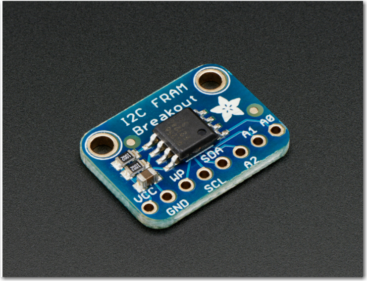
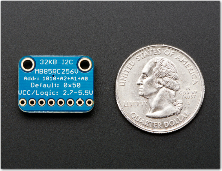
Well, it appears I spoke too soon about having solved the I2C hangup problem on my Wall-E2 wall-following robot. In my last post on this subject, I described all the troubleshooting efforts I employed to nail down the cause of intermittent hangups when trying to use the MPU6050 6DOF IMU on the robot, along with several other I2C devices (a Teensy 3.5 used for IR homing, and Adafruit RTC, and FRAM modules).
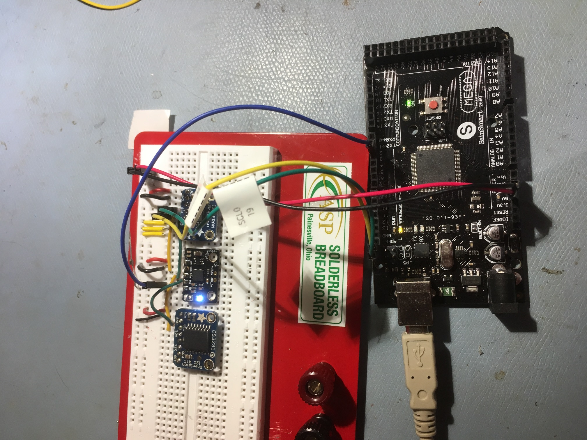
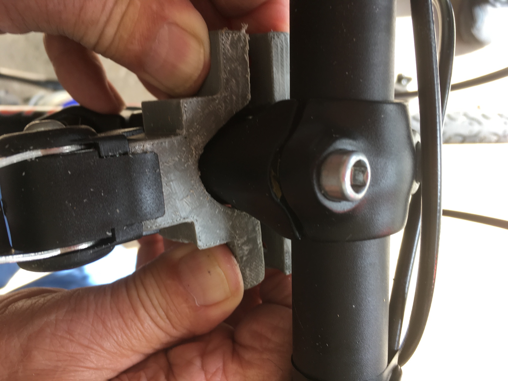
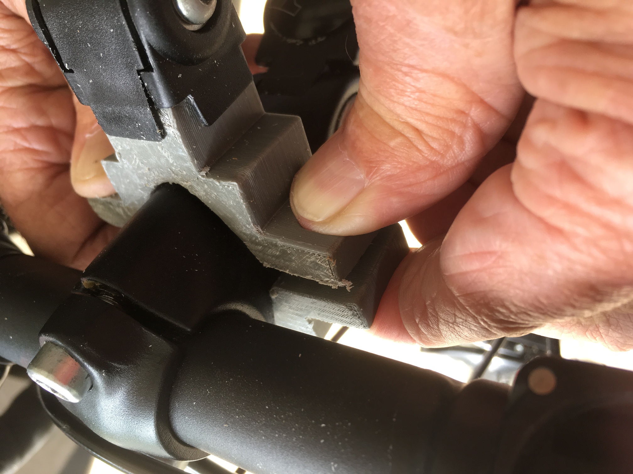
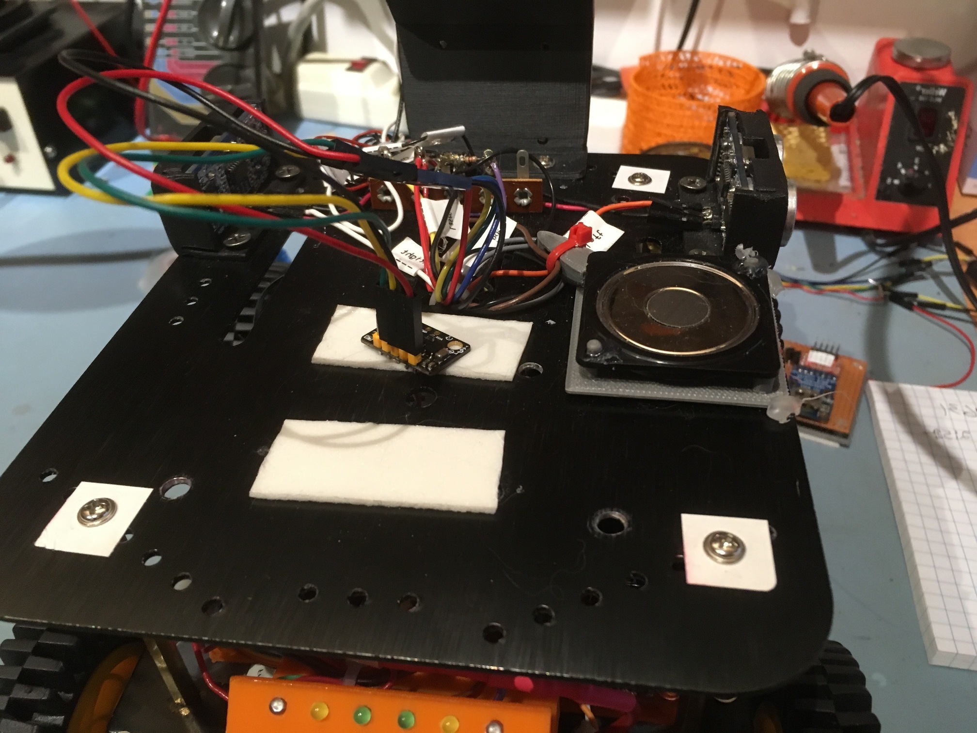
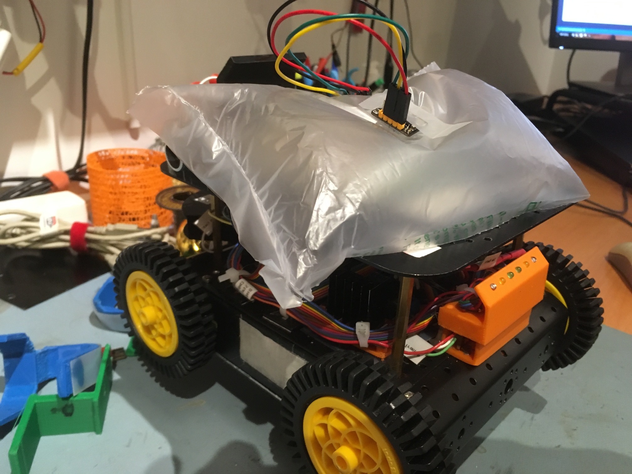
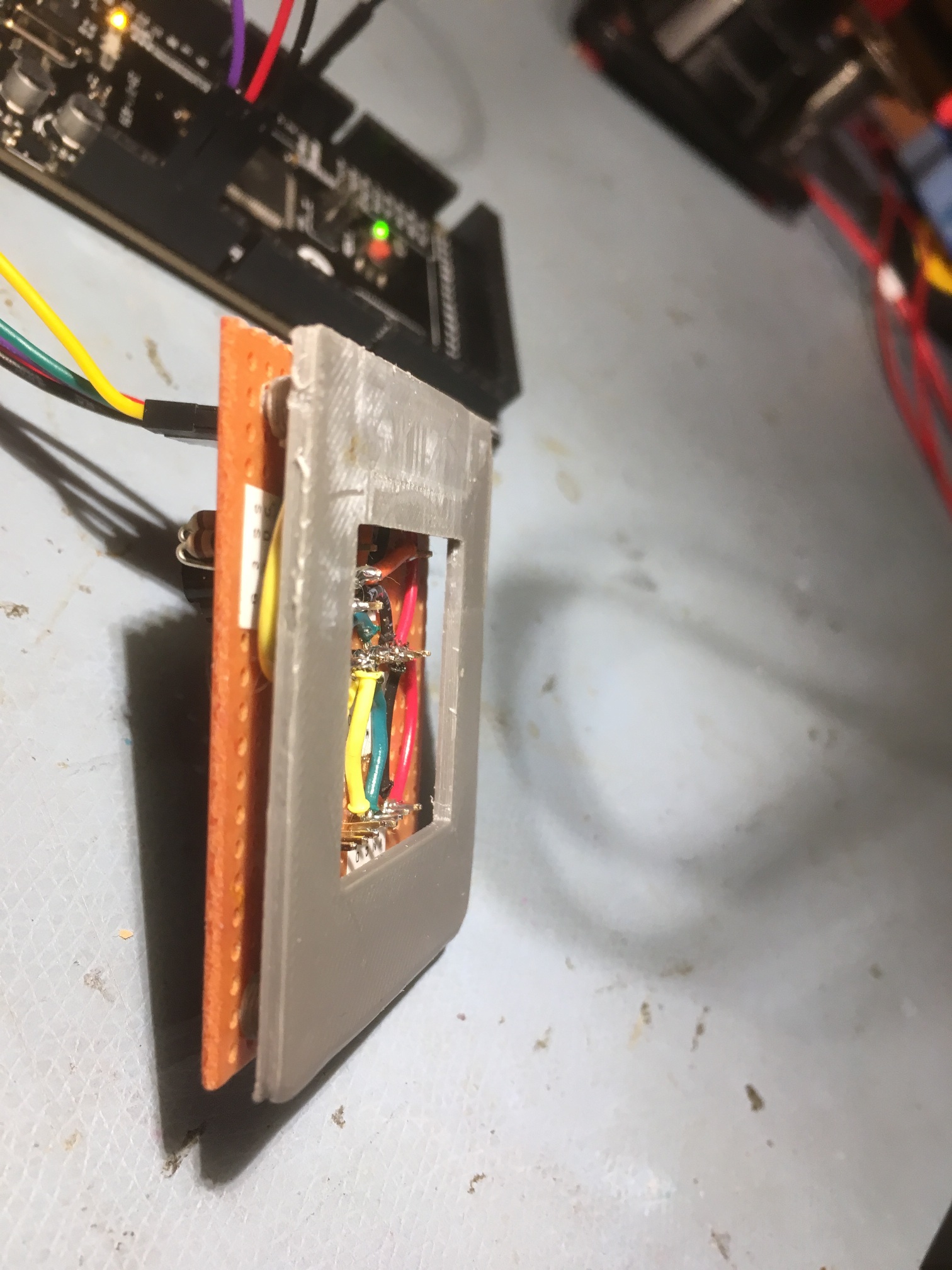
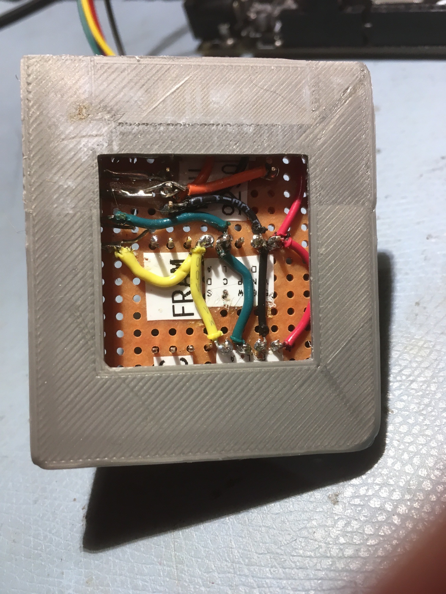
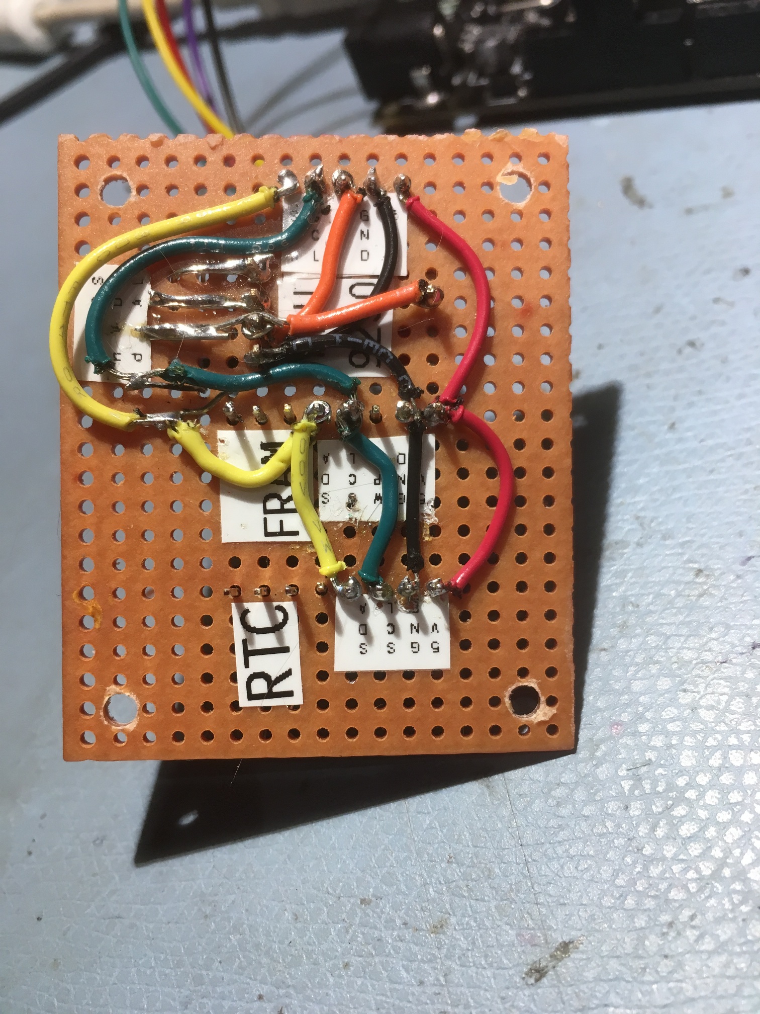
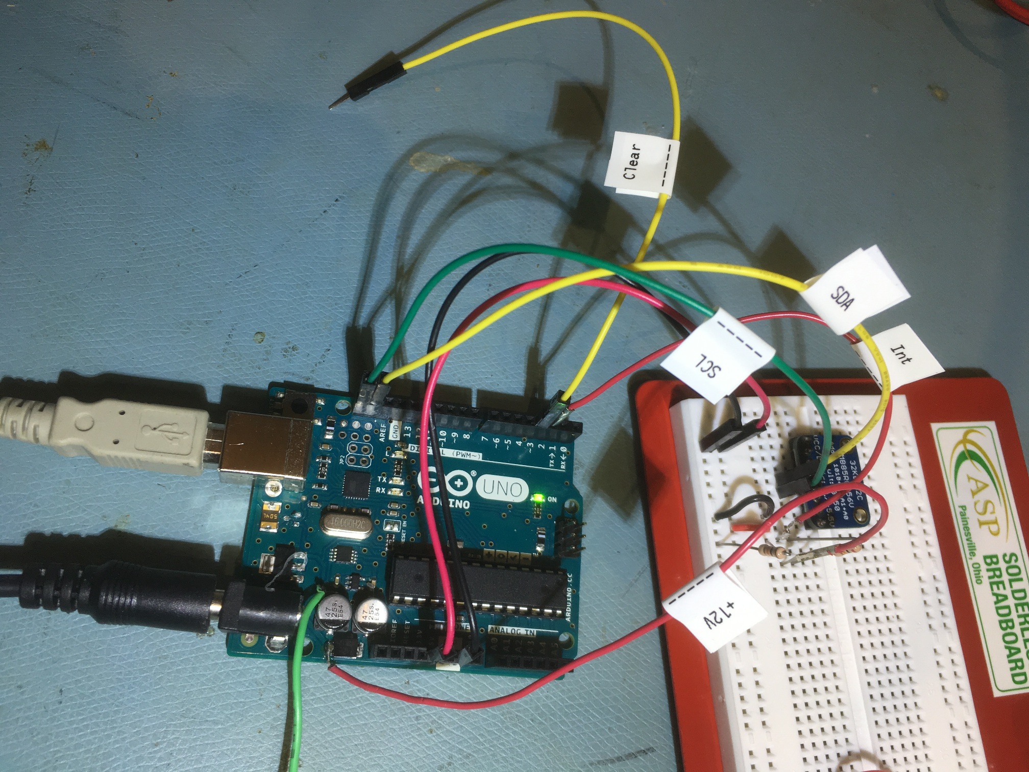
After (I thought) figuring out that the I2C SCL/SDA line lengths were the root problem of the hangups I had been experiencing, my grandson Danny and I spent some quality time reworking Wall-E2’s layout to accommodate shorter line lengths. Instead of mounting the IMU and it’s companion sensors on the second deck as before, we 3D printed a small plastic plate to attach to one of the hexagonal 2nd deck standoff posts and provide a 1st deck mounting area for the sensors. The previous and new mounting locations are shown below:
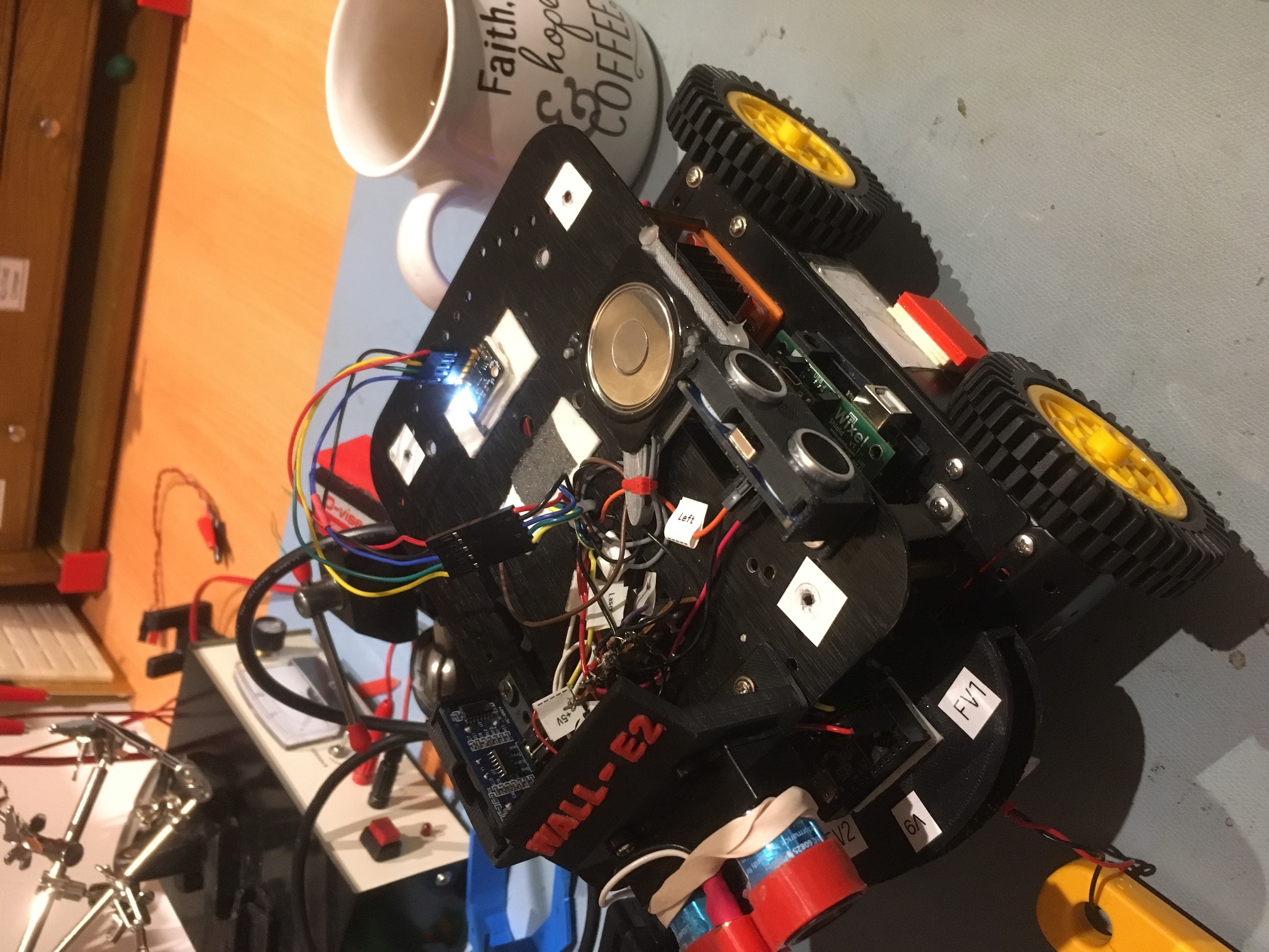
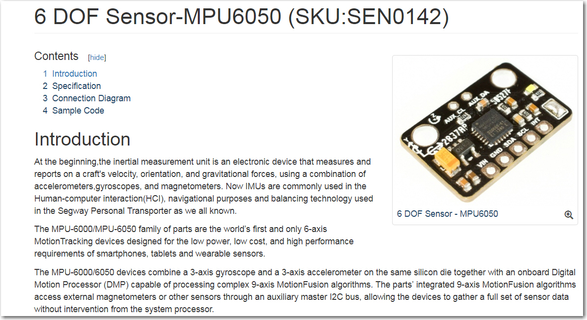
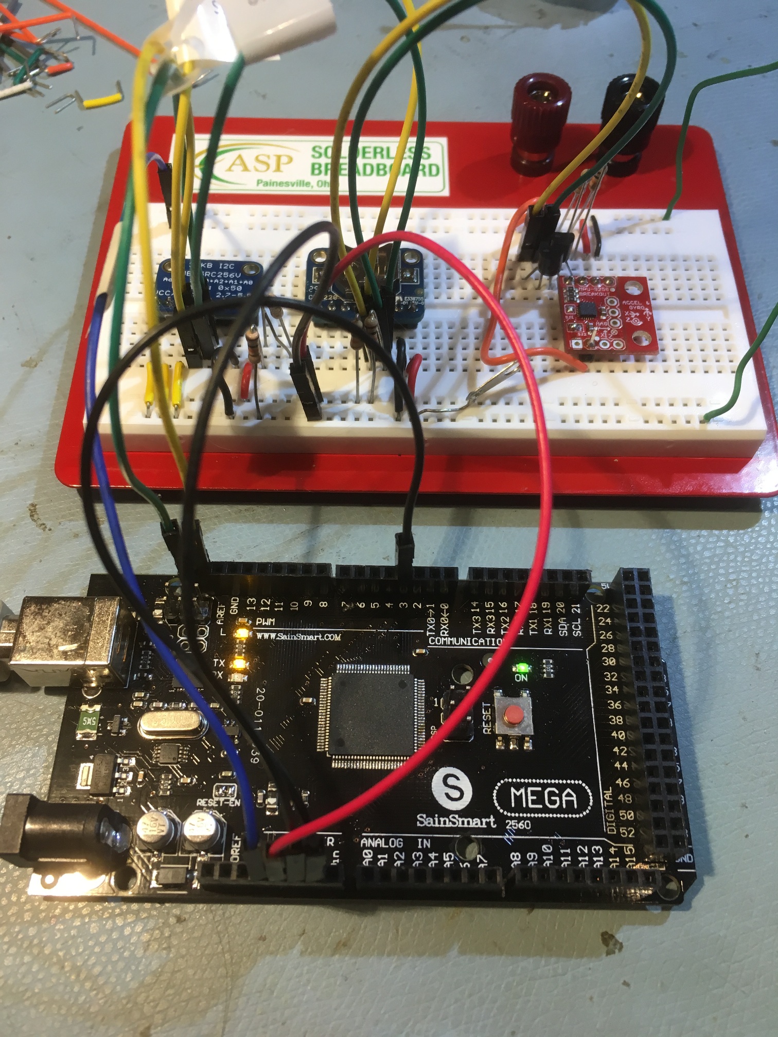
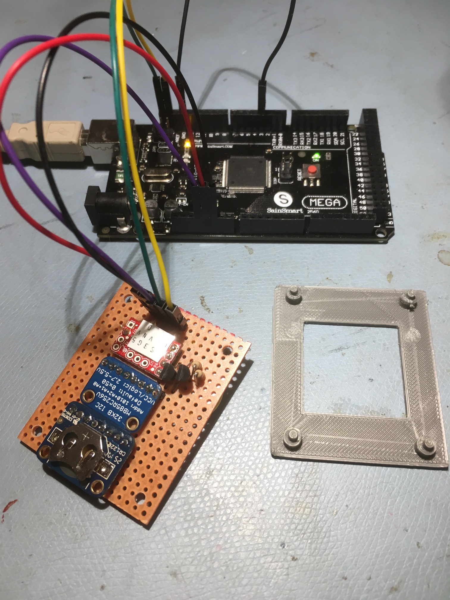
2nd deck mounting location. The MPU6050 is the module with the illuminated blue LED toward the rear of the robot
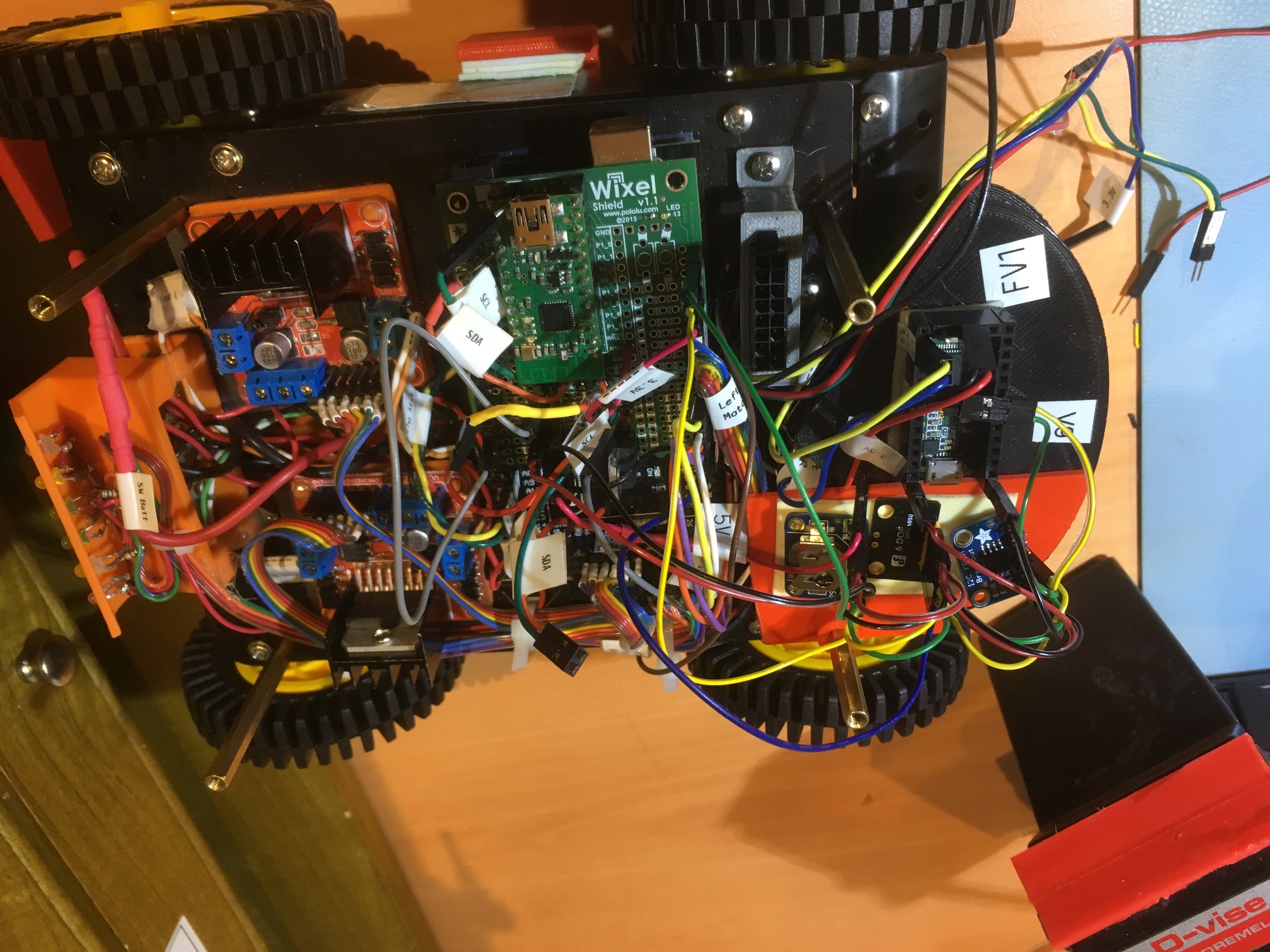
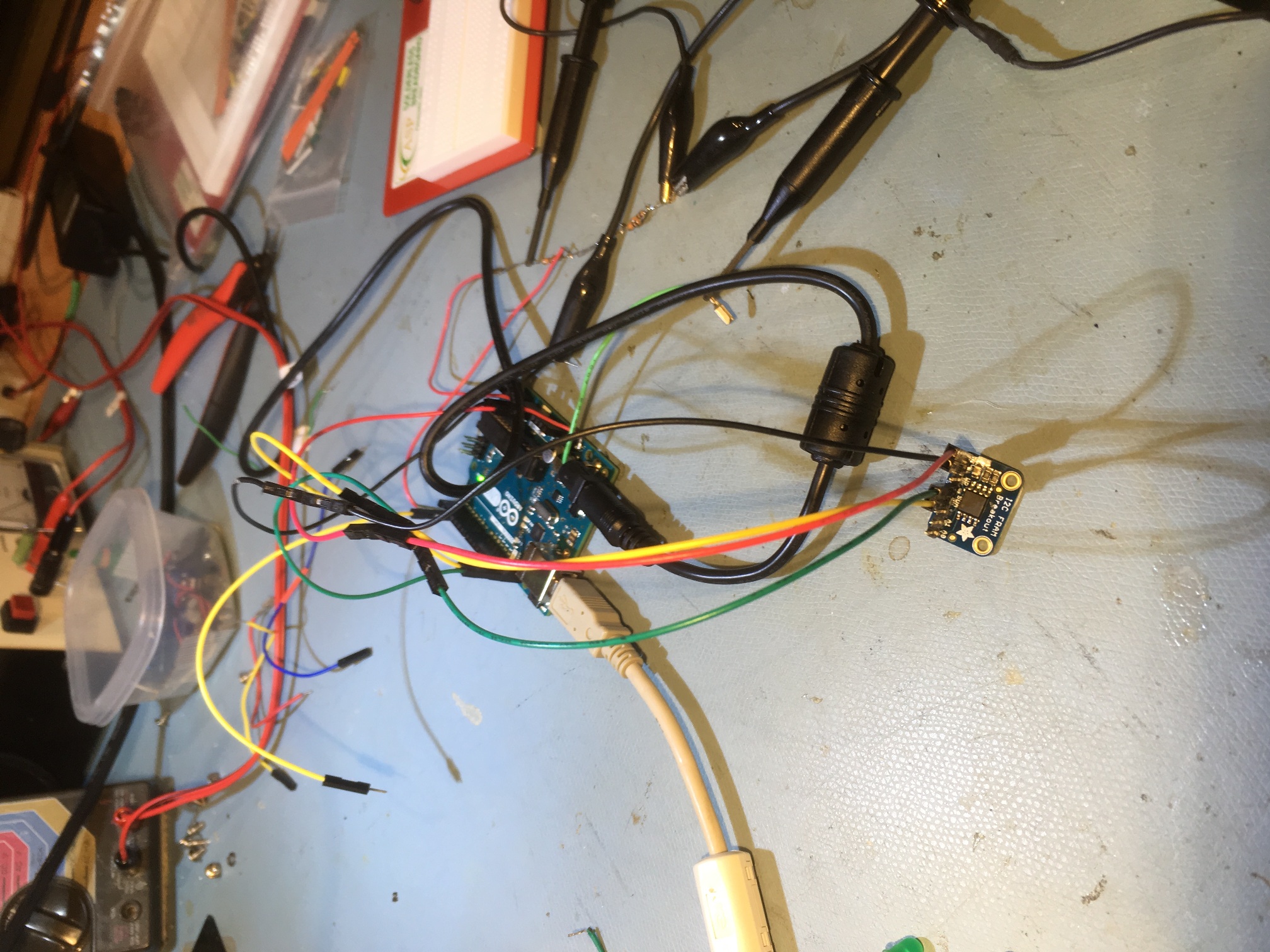
1st deck mounting location for I2C sensors (lower right-hand corner of the photo). The Teensy 3.5 IR homing module is shown mounted on the IR detector housing (above the red plastic plate)
Unfortunately, as I was doing some final tests on this setup, I started experiencing hangups again. After a day or so moping and some very choice words, I started all over again trying to figure out what happened.
On previous searches through the i-verse, I had run across several posts indicating that the Arduino Wire library had some basic problems with I2C bus edge conditions; there were several places where it uses several blocking ‘while()’ loops to transmit and receive data on the I2C bus, and there was no way to recover from a ‘while()’ loop where the exit condition was never satisfied. After literally exhausting all the other possibilities, it was becoming apparent that this must be what was happening – the MPU6050 must occasionally fail to respond correctly to a I2C transaction, causing the associated ‘while()’ loop to never exit.
So, I started looking for solutions to this problem. Again, I found some posts where folks had modified the low-level I2C bus handling code found in twi.c/.h, the code underlying the Android Wire class. I found a post by ‘unaie’ (http://forum.arduino.cc/index.php/topic,19624.0.html) with the same complaint, but he also posted modified versions of twi.c and twi.h that solved these problems by forcing the ‘while()’ loops to exit after a set number of iterations, and resetting the I2C bus when this happens. His modified versions can be downloaded at:
http://liken.otsoa.net/pub/ntwi/twi.h
http://liken.otsoa.net/pub/ntwi/twi.c
I downloaded these files and tried to replace the ‘stock’ twi.c/h with the modified versions. Unfortunately, unaie’s modifications were made on a quite old version of the files, and conflicted with the later ‘repeated start’ versions of these files that are in the current ‘wire’ library.
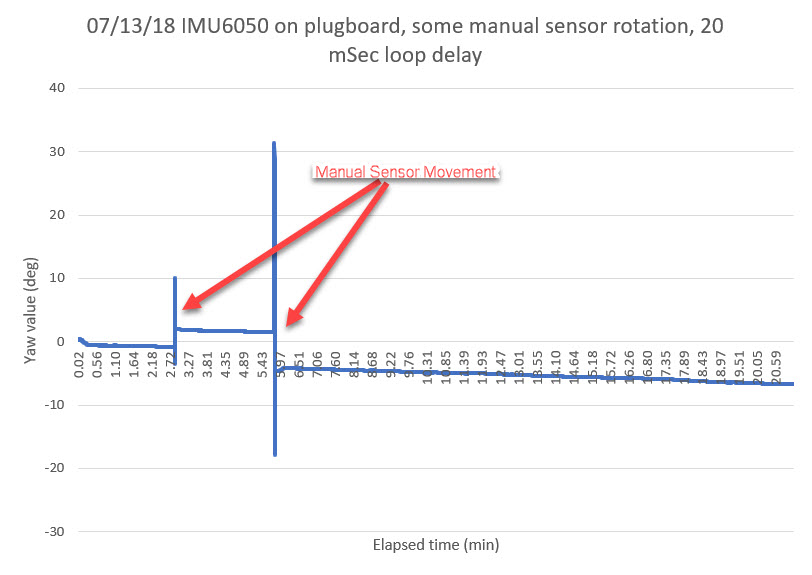
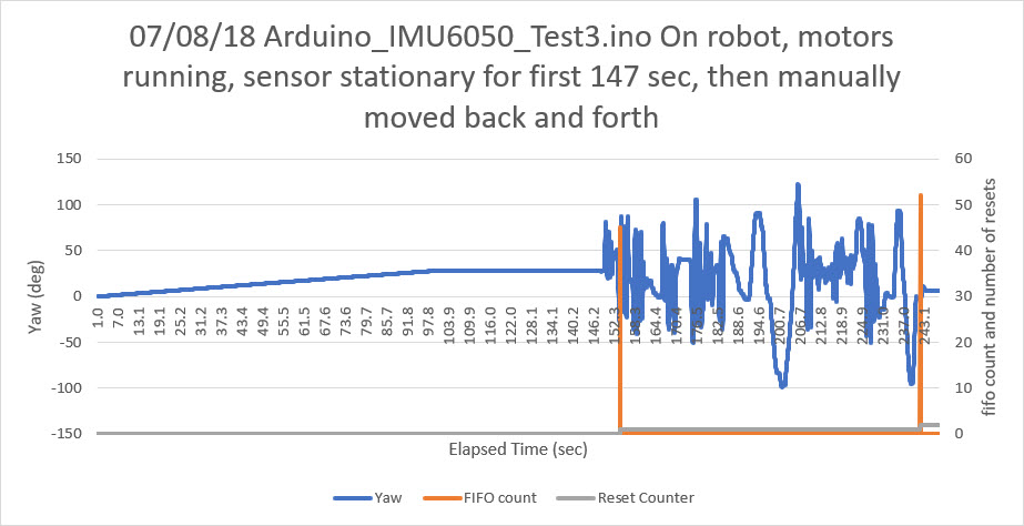
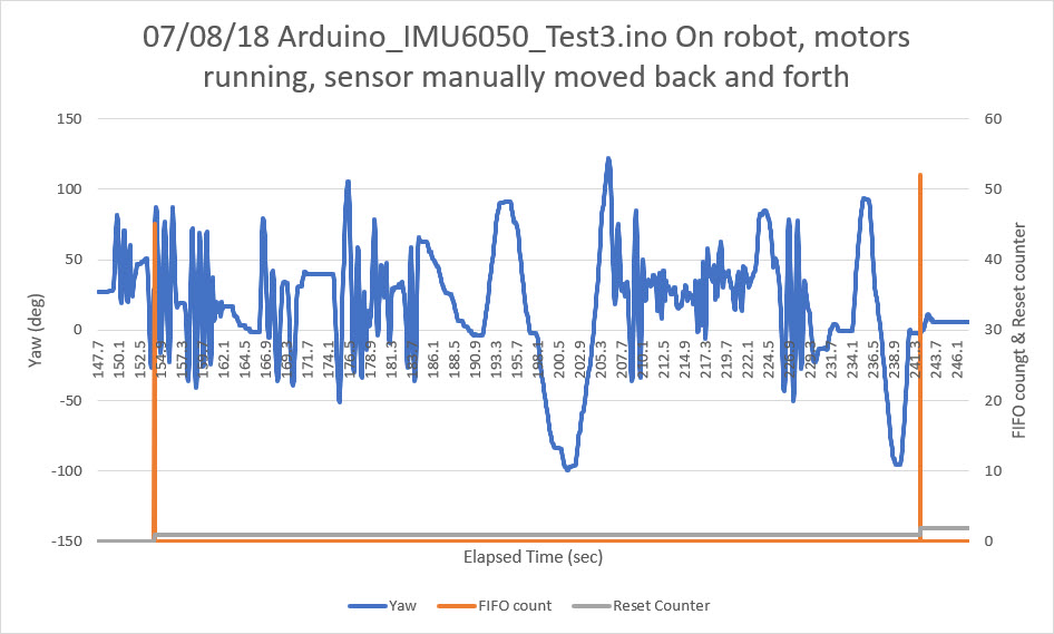
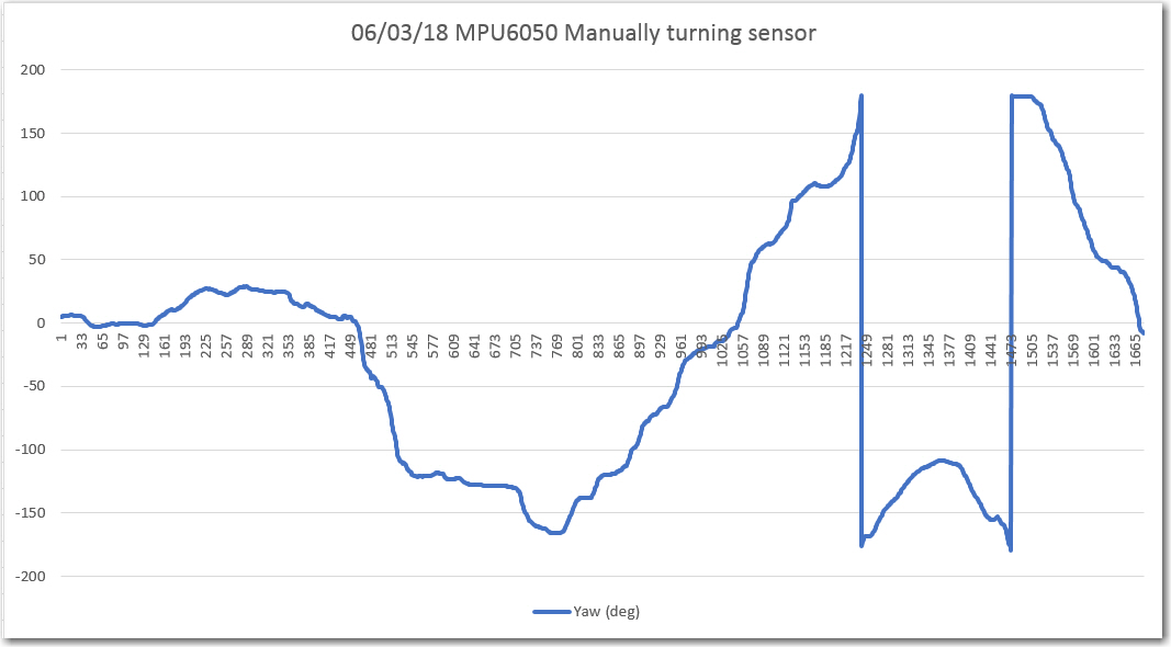
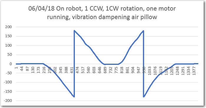
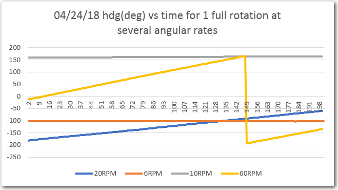
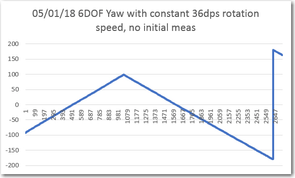
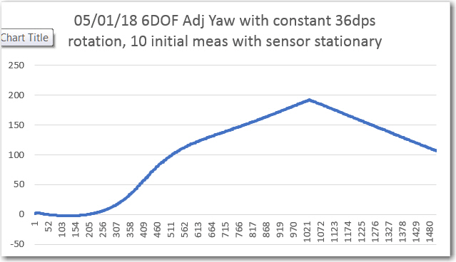
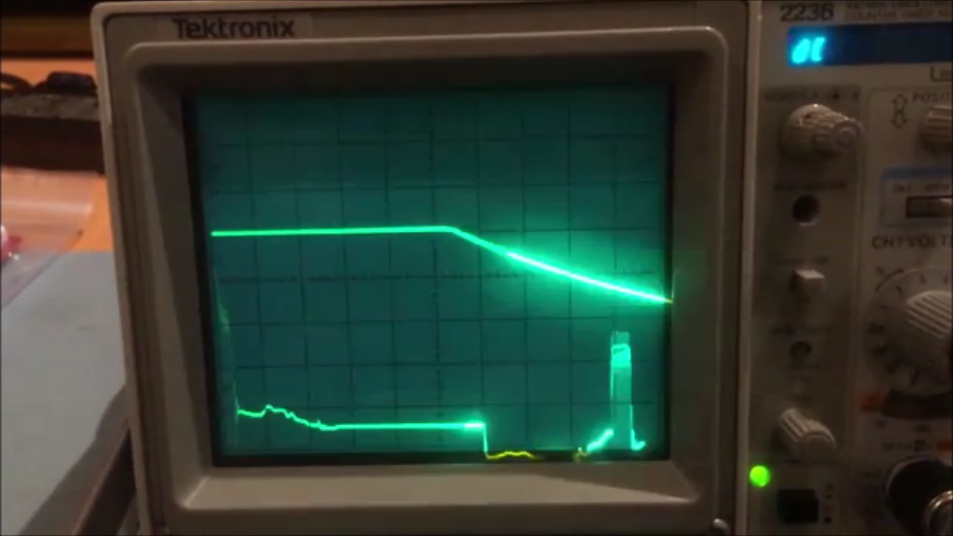
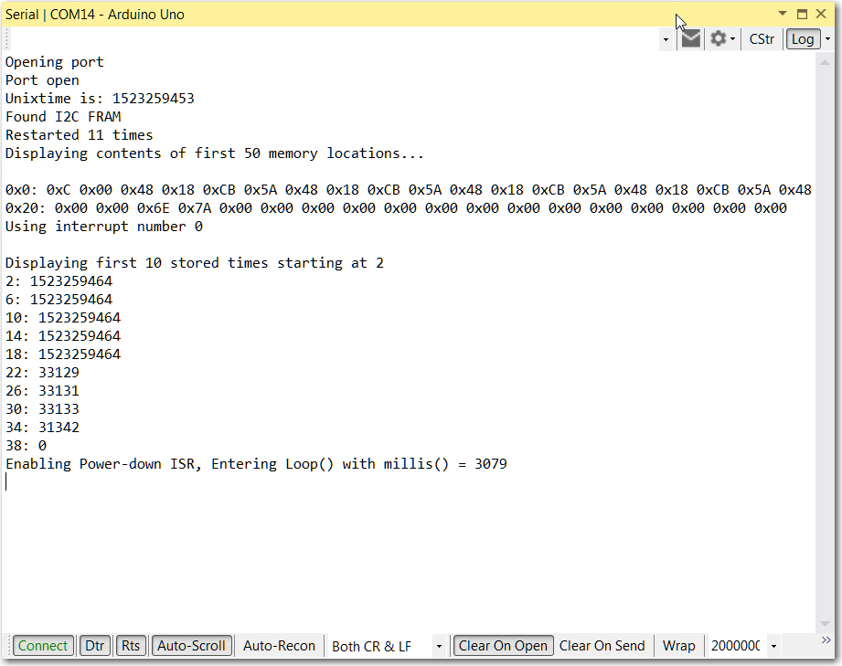
So, I did a ‘diff’ between the ‘repeated start’ version and unaie’s version, and created a modified version of the latest ‘repeated start’ twi.c/h. In addition, I added a couple of functions to allow monitoring of the number of times a bus reset was required due to a ‘while()’ loop timeout. When I was finished, I ran the sensor for over 24 hours with no failures, but in that time there were three instances where a ‘while()’ loop timed out and a I2C bus reset was required. A small snippet of this run is shown below. The blue line is the yaw value, and the plot snippet shows where I manually rotated the sensor just after 24 hours, and the horizontal orange line shows the number of bus resets.
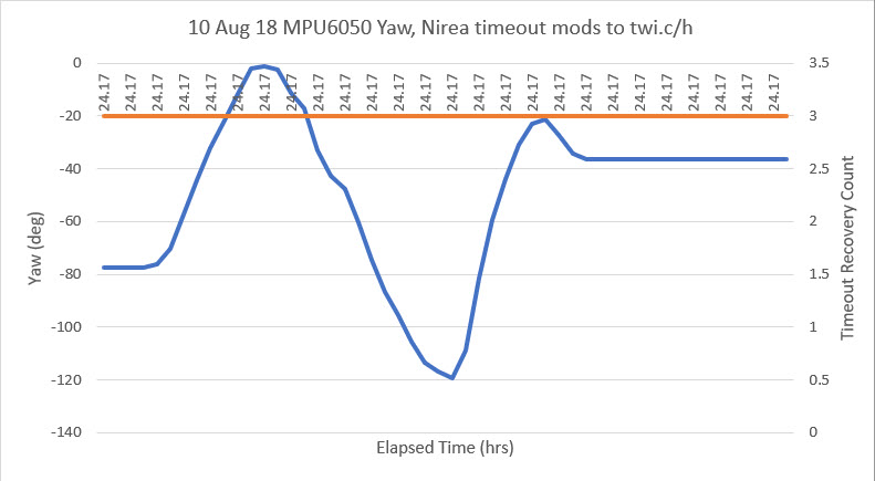
Small snippet of 24-hour sensor run. blue line is reported yaw value; orange shows the I2C bus reset counter
So it is clear that, absent the lockup recovery modifications, the I2C bus would have locked up long before, and that with the modifications ‘while()’ loop deadlocks have been successfully handled.
11 August 2018 Update:
The sensor is still going strong after 44 hours with no hangups, and the reset counter is still holding at 3.
The complete twi.c & twi.h codes are included below:
|
1 2 3 4 5 6 7 8 9 10 11 12 13 14 15 16 17 18 19 20 21 22 23 24 25 26 27 28 29 30 31 32 33 34 35 36 37 38 39 40 41 42 43 44 45 46 47 48 49 50 51 52 53 54 55 56 57 58 59 60 61 62 63 64 65 66 67 68 69 70 71 72 73 74 75 76 77 78 79 80 81 82 83 84 85 86 87 88 89 90 91 92 93 94 95 96 97 98 99 100 101 102 103 104 105 106 107 108 109 110 111 112 113 114 115 116 117 118 119 120 121 122 123 124 125 126 127 128 129 130 131 132 133 134 135 136 137 138 139 140 141 142 143 144 145 146 147 148 149 150 151 152 153 154 155 156 157 158 159 160 161 162 163 164 165 166 167 168 169 170 171 172 173 174 175 176 177 178 179 180 181 182 183 184 185 186 187 188 189 190 191 192 193 194 195 196 197 198 199 200 201 202 203 204 205 206 207 208 209 210 211 212 213 214 215 216 217 218 219 220 221 222 223 224 225 226 227 228 229 230 231 232 233 234 235 236 237 238 239 240 241 242 243 244 245 246 247 248 249 250 251 252 253 254 255 256 257 258 259 260 261 262 263 264 265 266 267 268 269 270 271 272 273 274 275 276 277 278 279 280 281 282 283 284 285 286 287 288 289 290 291 292 293 294 295 296 297 298 299 300 301 302 303 304 305 306 307 308 309 310 311 312 313 314 315 316 317 318 319 320 321 322 323 324 325 326 327 328 329 330 331 332 333 334 335 336 337 338 339 340 341 342 343 344 345 346 347 348 349 350 351 352 353 354 355 356 357 358 359 360 361 362 363 364 365 366 367 368 369 370 371 372 373 374 375 376 377 378 379 380 381 382 383 384 385 386 387 388 389 390 391 392 393 394 395 396 397 398 399 400 401 402 403 404 405 406 407 408 409 410 411 412 413 414 415 416 417 418 419 420 421 422 423 424 425 426 427 428 429 430 431 432 433 434 435 436 437 438 439 440 441 442 443 444 445 446 447 448 449 450 451 452 453 454 455 456 457 458 459 460 461 462 463 464 465 466 467 468 469 470 471 472 473 474 475 476 477 478 479 480 481 482 483 484 485 486 487 488 489 490 491 492 493 494 495 496 497 498 499 500 501 502 503 504 505 506 507 508 509 510 511 512 513 514 515 516 517 518 519 520 521 522 523 524 525 526 527 528 529 530 531 532 533 534 535 536 537 538 539 540 541 542 543 544 545 546 547 548 549 550 551 552 553 554 555 556 557 558 559 560 561 562 563 564 565 566 567 568 569 570 571 572 573 574 575 576 577 578 579 580 581 582 583 584 585 586 587 588 589 590 591 592 593 594 595 596 597 598 599 600 601 602 603 604 605 606 607 |
/* twi.c - TWI/I2C library for Wiring & Arduino Copyright (c) 2006 Nicholas Zambetti. All right reserved. This library is free software; you can redistribute it and/or modify it under the terms of the GNU Lesser General Public License as published by the Free Software Foundation; either version 2.1 of the License, or (at your option) any later version. This library is distributed in the hope that it will be useful, but WITHOUT ANY WARRANTY; without even the implied warranty of MERCHANTABILITY or FITNESS FOR A PARTICULAR PURPOSE. See the GNU Lesser General Public License for more details. You should have received a copy of the GNU Lesser General Public License along with this library; if not, write to the Free Software Foundation, Inc., 51 Franklin St, Fifth Floor, Boston, MA 02110-1301 USA Modified 2012 by Todd Krein (todd@krein.org) to implement repeated starts */ //08/09/18 this file has been merged with unaie's version of twi.c, modified to recover from infinite hang conditions //see http://forum.arduino.cc/index.php/topic,19624.0.html for details //this file should be renamed 'twi.c' and placed so that it gets used instead of the normal one. #include <math.h> #include <stdlib.h> #include <inttypes.h> #include <avr/io.h> #include <avr/interrupt.h> #include <compat/twi.h> #include "Arduino.h" // for digitalWrite #ifndef cbi #define cbi(sfr, bit) (_SFR_BYTE(sfr) &= ~_BV(bit)) #endif #ifndef sbi #define sbi(sfr, bit) (_SFR_BYTE(sfr) |= _BV(bit)) #endif #include "pins_arduino.h" #include "twi.h" static volatile uint8_t trcase;//Nir static volatile uint8_t twi_state; static volatile uint8_t twi_slarw; static volatile uint8_t twi_sendStop; // should the transaction end with a stop static volatile uint8_t twi_inRepStart; // in the middle of a repeated start static void (*twi_onSlaveTransmit)(void); static void (*twi_onSlaveReceive)(uint8_t*, int); static uint8_t twi_masterBuffer[TWI_BUFFER_LENGTH]; static volatile uint8_t twi_masterBufferIndex; static volatile uint8_t twi_masterBufferLength; static uint8_t twi_txBuffer[TWI_BUFFER_LENGTH]; static volatile uint8_t twi_txBufferIndex; static volatile uint8_t twi_txBufferLength; static uint8_t twi_rxBuffer[TWI_BUFFER_LENGTH]; static volatile uint8_t twi_rxBufferIndex; static volatile uint8_t twi_error; //08/09/18 gfp - added to monitor lockup recoveries static uint16_t lockup_recovery_count = 0; /* * Function twi_init * Desc readys twi pins and sets twi bitrate * Input none * Output none */ void twi_init(void) { // disable twi module (to allow for reinitialize) TWCR = 0; //08/09/18 - required to get TWI to re-init // initialize state twi_state = TWI_READY; twi_sendStop = true; // default value twi_inRepStart = false; // activate internal pullups for twi. digitalWrite(SDA, 1); digitalWrite(SCL, 1); // initialize twi prescaler and bit rate cbi(TWSR, TWPS0); cbi(TWSR, TWPS1); TWBR = ((F_CPU / TWI_FREQ) - 16) / 2; /* twi bit rate formula from atmega128 manual pg 204 SCL Frequency = CPU Clock Frequency / (16 + (2 * TWBR)) note: TWBR should be 10 or higher for master mode It is 72 for a 16mhz Wiring board with 100kHz TWI */ // enable twi module, acks, and twi interrupt TWCR = _BV(TWEN) | _BV(TWIE) | _BV(TWEA); } /* * Function twi_disable * Desc disables twi pins * Input none * Output none */ void twi_disable(void) { // disable twi module, acks, and twi interrupt TWCR &= ~(_BV(TWEN) | _BV(TWIE) | _BV(TWEA)); // deactivate internal pullups for twi. digitalWrite(SDA, 0); digitalWrite(SCL, 0); } /* * Function twi_slaveInit * Desc sets slave address and enables interrupt * Input none * Output none */ void twi_setAddress(uint8_t address) { // set twi slave address (skip over TWGCE bit) TWAR = address << 1; } /* * Function twi_setClock * Desc sets twi bit rate * Input Clock Frequency * Output none */ void twi_setFrequency(uint32_t frequency) { TWBR = ((F_CPU / frequency) - 16) / 2; /* twi bit rate formula from atmega128 manual pg 204 SCL Frequency = CPU Clock Frequency / (16 + (2 * TWBR)) note: TWBR should be 10 or higher for master mode It is 72 for a 16mhz Wiring board with 100kHz TWI */ } /* * Function twi_readFrom * Desc attempts to become twi bus master and read a * series of bytes from a device on the bus * Input address: 7bit i2c device address * data: pointer to byte array * length: number of bytes to read into array * sendStop: Boolean indicating whether to send a stop at the end * Output number of bytes read */ uint8_t twi_readFrom(uint8_t address, uint8_t* data, uint8_t length, uint8_t sendStop) { uint8_t i; // ensure data will fit into buffer if(TWI_BUFFER_LENGTH < length){ return 0; } // wait until twi is ready, become master receiver twi_tout(1);//Ini TimeOut while(TWI_READY != twi_state){ if (twi_tout(0)) break; continue; } twi_state = TWI_MRX; twi_sendStop = sendStop; // reset error state (0xFF.. no error occured) twi_error = 0xFF; // initialize buffer iteration vars twi_masterBufferIndex = 0; twi_masterBufferLength = length-1; // This is not intuitive, read on... // On receive, the previously configured ACK/NACK setting is transmitted in // response to the received byte before the interrupt is signalled. // Therefor we must actually set NACK when the _next_ to last byte is // received, causing that NACK to be sent in response to receiving the last // expected byte of data. // build sla+w, slave device address + w bit twi_slarw = TW_READ; twi_slarw |= address << 1; if (true == twi_inRepStart) { // if we're in the repeated start state, then we've already sent the start, // (@@@ we hope), and the TWI statemachine is just waiting for the address byte. // We need to remove ourselves from the repeated start state before we enable interrupts, // since the ISR is ASYNC, and we could get confused if we hit the ISR before cleaning // up. Also, don't enable the START interrupt. There may be one pending from the // repeated start that we sent ourselves, and that would really confuse things. twi_inRepStart = false; // remember, we're dealing with an ASYNC ISR do { TWDR = twi_slarw; } while(TWCR & _BV(TWWC)); TWCR = _BV(TWINT) | _BV(TWEA) | _BV(TWEN) | _BV(TWIE); // enable INTs, but not START } else // send start condition TWCR = _BV(TWEN) | _BV(TWIE) | _BV(TWEA) | _BV(TWINT) | _BV(TWSTA); // wait for read operation to complete twi_tout(1); while(TWI_MRX == twi_state){ if (twi_tout(0)) break; continue; } if (twi_masterBufferIndex < length) length = twi_masterBufferIndex; // copy twi buffer to data for(i = 0; i < length; ++i){ data[i] = twi_masterBuffer[i]; } return length; } /* * Function twi_writeTo * Desc attempts to become twi bus master and write a * series of bytes to a device on the bus * Input address: 7bit i2c device address * data: pointer to byte array * length: number of bytes in array * wait: boolean indicating to wait for write or not * sendStop: boolean indicating whether or not to send a stop at the end * Output 0 .. success * 1 .. length to long for buffer * 2 .. address send, NACK received * 3 .. data send, NACK received * 4 .. other twi error (lost bus arbitration, bus error, ..) */ uint8_t twi_writeTo(uint8_t address, uint8_t* data, uint8_t length, uint8_t wait, uint8_t sendStop) { uint8_t i; // ensure data will fit into buffer if(TWI_BUFFER_LENGTH < length){ return 1; } // wait until twi is ready, become master transmitter twi_tout(1); while(TWI_READY != twi_state){ if (twi_tout(0)) return 5; continue; } twi_state = TWI_MTX; twi_sendStop = sendStop; // reset error state (0xFF.. no error occured) twi_error = 0xFF; // initialize buffer iteration vars twi_masterBufferIndex = 0; twi_masterBufferLength = length; // copy data to twi buffer for(i = 0; i < length; ++i){ twi_masterBuffer[i] = data[i]; } // build sla+w, slave device address + w bit twi_slarw = TW_WRITE; twi_slarw |= address << 1; // if we're in a repeated start, then we've already sent the START // in the ISR. Don't do it again. // if (true == twi_inRepStart) { // if we're in the repeated start state, then we've already sent the start, // (@@@ we hope), and the TWI statemachine is just waiting for the address byte. // We need to remove ourselves from the repeated start state before we enable interrupts, // since the ISR is ASYNC, and we could get confused if we hit the ISR before cleaning // up. Also, don't enable the START interrupt. There may be one pending from the // repeated start that we sent outselves, and that would really confuse things. twi_inRepStart = false; // remember, we're dealing with an ASYNC ISR do { TWDR = twi_slarw; } while(TWCR & _BV(TWWC)); TWCR = _BV(TWINT) | _BV(TWEA) | _BV(TWEN) | _BV(TWIE); // enable INTs, but not START } else // send start condition TWCR = _BV(TWINT) | _BV(TWEA) | _BV(TWEN) | _BV(TWIE) | _BV(TWSTA); // enable INTs // wait for write operation to complete twi_tout(1); while(wait && (TWI_MTX == twi_state)){ if (twi_tout(0)) return 5; continue; } if (twi_error == 0xFF) return 0; // success else if (twi_error == TW_MT_SLA_NACK) return 2; // error: address send, nack received else if (twi_error == TW_MT_DATA_NACK) return 3; // error: data send, nack received else return 4; // other twi error } /* * Function twi_transmit * Desc fills slave tx buffer with data * must be called in slave tx event callback * Input data: pointer to byte array * length: number of bytes in array * Output 1 length too long for buffer * 2 not slave transmitter * 0 ok */ uint8_t twi_transmit(const uint8_t* data, uint8_t length) { uint8_t i; // ensure data will fit into buffer if(TWI_BUFFER_LENGTH < (twi_txBufferLength+length)){ return 1; } // ensure we are currently a slave transmitter if(TWI_STX != twi_state){ return 2; } // set length and copy data into tx buffer for(i = 0; i < length; ++i){ twi_txBuffer[twi_txBufferLength+i] = data[i]; } twi_txBufferLength += length; return 0; } /* * Function twi_attachSlaveRxEvent * Desc sets function called before a slave read operation * Input function: callback function to use * Output none */ void twi_attachSlaveRxEvent( void (*function)(uint8_t*, int) ) { twi_onSlaveReceive = function; } /* * Function twi_attachSlaveTxEvent * Desc sets function called before a slave write operation * Input function: callback function to use * Output none */ void twi_attachSlaveTxEvent( void (*function)(void) ) { twi_onSlaveTransmit = function; } /* * Function twi_reply * Desc sends byte or readys receive line * Input ack: byte indicating to ack or to nack * Output none */ void twi_reply(uint8_t ack) { // transmit master read ready signal, with or without ack if(ack){ TWCR = _BV(TWEN) | _BV(TWIE) | _BV(TWINT) | _BV(TWEA); }else{ TWCR = _BV(TWEN) | _BV(TWIE) | _BV(TWINT); } } /* * Function twi_stop * Desc relinquishes bus master status * Input none * Output none */ void twi_stop(void) { // send stop condition TWCR = _BV(TWEN) | _BV(TWIE) | _BV(TWEA) | _BV(TWINT) | _BV(TWSTO); // wait for stop condition to be exectued on bus // TWINT is not set after a stop condition! twi_tout(1); while(TWCR & _BV(TWSTO)){ if (twi_tout(0)) return; continue; } // update twi state twi_state = TWI_READY; } /* * Function twi_releaseBus * Desc releases bus control * Input none * Output none */ void twi_releaseBus(void) { // release bus TWCR = _BV(TWEN) | _BV(TWIE) | _BV(TWEA) | _BV(TWINT); // update twi state twi_state = TWI_READY; } //Nirea. Time Out static volatile uint32_t twi_toutc; uint8_t twi_tout(uint8_t ini) { if (ini) twi_toutc=0; else twi_toutc++; if (twi_toutc>=100000UL) { twi_toutc=0; twi_init(); lockup_recovery_count++; return 1; } return 0; } void twi_clearRecoveryCount() //08/09/18 gfp for monitoring purposes { lockup_recovery_count = 0; } uint16_t twi_getRecoveryCount() //08/09/18 gfp for monitoring purposes { return lockup_recovery_count; } ISR(TWI_vect) { switch(TW_STATUS){ // All Master case TW_START: // sent start condition case TW_REP_START: // sent repeated start condition // copy device address and r/w bit to output register and ack TWDR = twi_slarw; twi_reply(1); break; // Master Transmitter case TW_MT_SLA_ACK: // slave receiver acked address case TW_MT_DATA_ACK: // slave receiver acked data // if there is data to send, send it, otherwise stop if(twi_masterBufferIndex < twi_masterBufferLength){ // copy data to output register and ack TWDR = twi_masterBuffer[twi_masterBufferIndex++]; twi_reply(1); }else{ if (twi_sendStop) twi_stop(); else { twi_inRepStart = true; // we're gonna send the START // don't enable the interrupt. We'll generate the start, but we // avoid handling the interrupt until we're in the next transaction, // at the point where we would normally issue the start. TWCR = _BV(TWINT) | _BV(TWSTA)| _BV(TWEN) ; twi_state = TWI_READY; } } break; case TW_MT_SLA_NACK: // address sent, nack received twi_error = TW_MT_SLA_NACK; twi_stop(); break; case TW_MT_DATA_NACK: // data sent, nack received twi_error = TW_MT_DATA_NACK; twi_stop(); break; case TW_MT_ARB_LOST: // lost bus arbitration twi_error = TW_MT_ARB_LOST; twi_releaseBus(); break; // Master Receiver case TW_MR_DATA_ACK: // data received, ack sent // put byte into buffer twi_masterBuffer[twi_masterBufferIndex++] = TWDR; case TW_MR_SLA_ACK: // address sent, ack received // ack if more bytes are expected, otherwise nack if(twi_masterBufferIndex < twi_masterBufferLength){ twi_reply(1); }else{ twi_reply(0); } break; case TW_MR_DATA_NACK: // data received, nack sent // put final byte into buffer twi_masterBuffer[twi_masterBufferIndex++] = TWDR; if (twi_sendStop) twi_stop(); else { twi_inRepStart = true; // we're gonna send the START // don't enable the interrupt. We'll generate the start, but we // avoid handling the interrupt until we're in the next transaction, // at the point where we would normally issue the start. TWCR = _BV(TWINT) | _BV(TWSTA)| _BV(TWEN) ; twi_state = TWI_READY; } break; case TW_MR_SLA_NACK: // address sent, nack received twi_stop(); break; // TW_MR_ARB_LOST handled by TW_MT_ARB_LOST case // Slave Receiver case TW_SR_SLA_ACK: // addressed, returned ack case TW_SR_GCALL_ACK: // addressed generally, returned ack case TW_SR_ARB_LOST_SLA_ACK: // lost arbitration, returned ack case TW_SR_ARB_LOST_GCALL_ACK: // lost arbitration, returned ack // enter slave receiver mode twi_state = TWI_SRX; // indicate that rx buffer can be overwritten and ack twi_rxBufferIndex = 0; twi_reply(1); break; case TW_SR_DATA_ACK: // data received, returned ack case TW_SR_GCALL_DATA_ACK: // data received generally, returned ack // if there is still room in the rx buffer if(twi_rxBufferIndex < TWI_BUFFER_LENGTH){ // put byte in buffer and ack twi_rxBuffer[twi_rxBufferIndex++] = TWDR; twi_reply(1); }else{ // otherwise nack twi_reply(0); } break; case TW_SR_STOP: // stop or repeated start condition received // ack future responses and leave slave receiver state twi_releaseBus(); // put a null char after data if there's room if(twi_rxBufferIndex < TWI_BUFFER_LENGTH){ twi_rxBuffer[twi_rxBufferIndex] = '\0'; } // callback to user defined callback twi_onSlaveReceive(twi_rxBuffer, twi_rxBufferIndex); // since we submit rx buffer to "wire" library, we can reset it twi_rxBufferIndex = 0; break; case TW_SR_DATA_NACK: // data received, returned nack case TW_SR_GCALL_DATA_NACK: // data received generally, returned nack // nack back at master twi_reply(0); break; // Slave Transmitter case TW_ST_SLA_ACK: // addressed, returned ack case TW_ST_ARB_LOST_SLA_ACK: // arbitration lost, returned ack // enter slave transmitter mode twi_state = TWI_STX; // ready the tx buffer index for iteration twi_txBufferIndex = 0; // set tx buffer length to be zero, to verify if user changes it twi_txBufferLength = 0; // request for txBuffer to be filled and length to be set // note: user must call twi_transmit(bytes, length) to do this twi_onSlaveTransmit(); // if they didn't change buffer & length, initialize it if(0 == twi_txBufferLength){ twi_txBufferLength = 1; twi_txBuffer[0] = 0x00; } // transmit first byte from buffer, fall case TW_ST_DATA_ACK: // byte sent, ack returned // copy data to output register TWDR = twi_txBuffer[twi_txBufferIndex++]; // if there is more to send, ack, otherwise nack if(twi_txBufferIndex < twi_txBufferLength){ twi_reply(1); }else{ twi_reply(0); } break; case TW_ST_DATA_NACK: // received nack, we are done case TW_ST_LAST_DATA: // received ack, but we are done already! // ack future responses twi_reply(1); // leave slave receiver state twi_state = TWI_READY; break; // All case TW_NO_INFO: // no state information break; case TW_BUS_ERROR: // bus error, illegal stop/start twi_error = TW_BUS_ERROR; twi_stop(); break; } } |
|
1 2 3 4 5 6 7 8 9 10 11 12 13 14 15 16 17 18 19 20 21 22 23 24 25 26 27 28 29 30 31 32 33 34 35 36 37 38 39 40 41 42 43 44 45 46 47 48 49 50 51 52 53 54 55 56 57 58 59 60 61 |
/* twi.h - TWI/I2C library for Wiring & Arduino Copyright (c) 2006 Nicholas Zambetti. All right reserved. This library is free software; you can redistribute it and/or modify it under the terms of the GNU Lesser General Public License as published by the Free Software Foundation; either version 2.1 of the License, or (at your option) any later version. This library is distributed in the hope that it will be useful, but WITHOUT ANY WARRANTY; without even the implied warranty of MERCHANTABILITY or FITNESS FOR A PARTICULAR PURPOSE. See the GNU Lesser General Public License for more details. You should have received a copy of the GNU Lesser General Public License along with this library; if not, write to the Free Software Foundation, Inc., 51 Franklin St, Fifth Floor, Boston, MA 02110-1301 USA */ //08/09/18 this has been merged with unaie's version of twi.h, modified to recover from infinite hang conditions //see http://forum.arduino.cc/index.php/topic,19624.0.html for details //this file should be renamed 'twi.h' and placed so that it gets used instead of the normal one. #ifndef twi_h #define twi_h #include <inttypes.h> //#define ATMEGA8 #ifndef TWI_FREQ #define TWI_FREQ 100000L #endif #ifndef TWI_BUFFER_LENGTH #define TWI_BUFFER_LENGTH 32 #endif #define TWI_READY 0 #define TWI_MRX 1 #define TWI_MTX 2 #define TWI_SRX 3 #define TWI_STX 4 void twi_init(void); void twi_disable(void); void twi_setAddress(uint8_t); void twi_setFrequency(uint32_t); uint8_t twi_readFrom(uint8_t, uint8_t*, uint8_t, uint8_t); uint8_t twi_writeTo(uint8_t, uint8_t*, uint8_t, uint8_t, uint8_t); uint8_t twi_transmit(const uint8_t*, uint8_t); void twi_attachSlaveRxEvent( void (*)(uint8_t*, int) ); void twi_attachSlaveTxEvent( void (*)(void) ); void twi_reply(uint8_t); void twi_stop(void); void twi_releaseBus(void); uint8_t twi_tout(uint8_t); //unaie's timeout function uint16_t twi_getRecoveryCount(); //08/09/18 gfp for monitoring purposes void twi_clearRecoveryCount(); //08/09/18 gfp for monitoring purposes #endif |
Stay tuned!
Frank