Posted 10 April 2021
In addition to using PID for homing to its charging station and for turn rate control, Wall-E2 also uses PID for finding the parallel orientation to a nearby wall. After successfully tuning the turn rate and IR Homing PID controllers using the Ziegler-Nichols method for PID tuning, I decided to see what I could do with the PID controller for parallel orientation finding
Wall-E2 uses two 3-element VL53L0X Time-of-Flight distance sensors for parallel orientation finding. The idea is that when all three sensors report the same distance, then the robot must be oriented parallel to the wall. The Teensy 3.5 Array Controller MCU calculates a ‘steering value’ using the expression (shown for the left side array):
|
1 |
LeftSteeringVal = (LF_Dist_mm - LR_Dist_mm) / 100.f; //rev 06/21/20 see PPalace post |
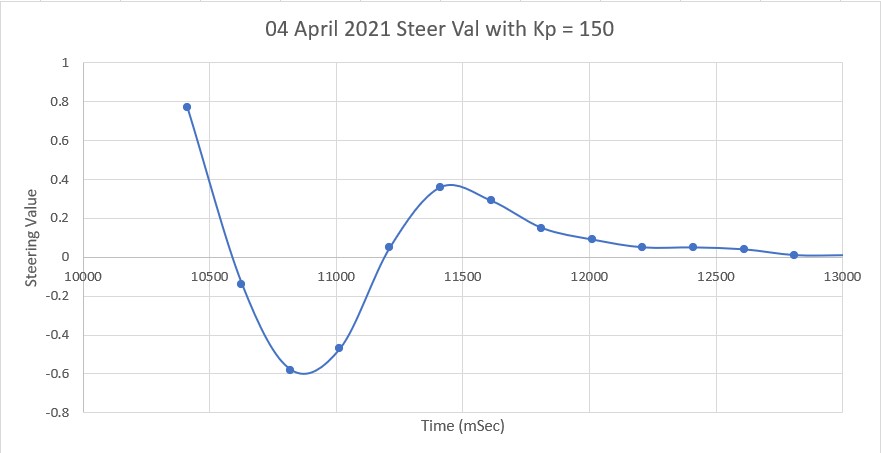
This value is fed to the PID engine, which drives the motors to zero it out – thus arriving at a parallel orientation. Originally I just basically ‘winged it’ in choosing PID Kp, Ki & Kd values, arriving emperically at Kp = 200, Ki = 50, Kd = 0. However, after going through the K-N process with Wall-E2’s other two PID control setups, I decided to try it with this one as well.
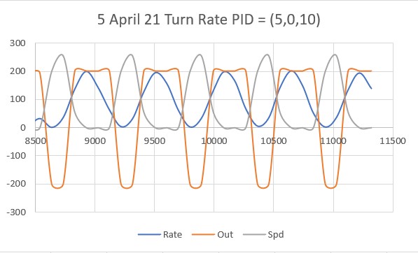
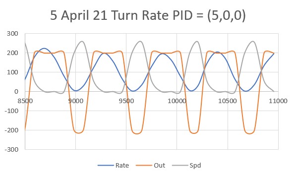
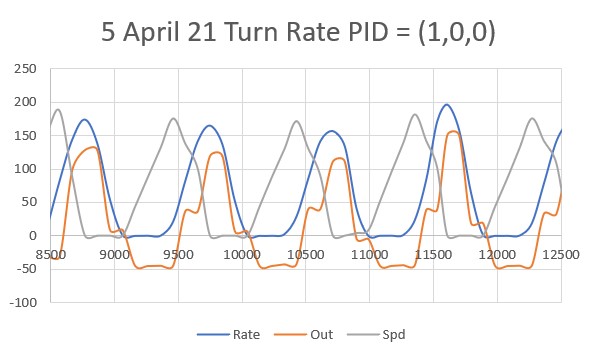
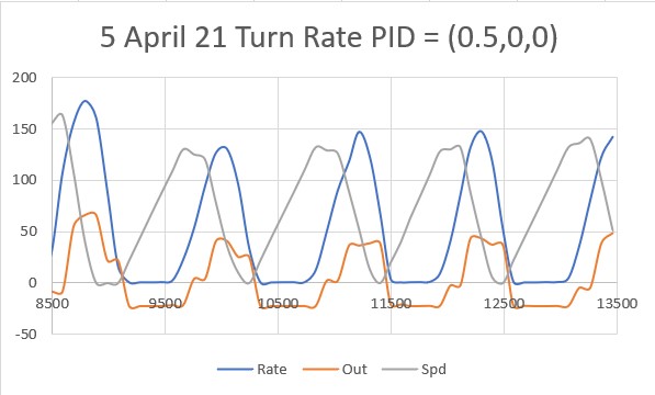
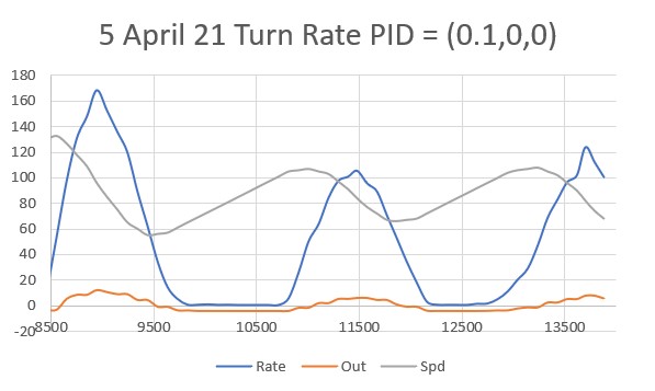
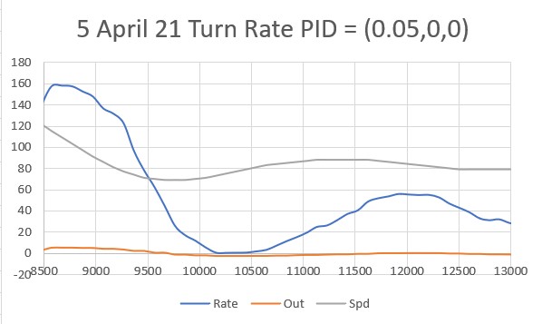
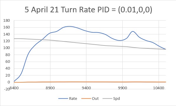
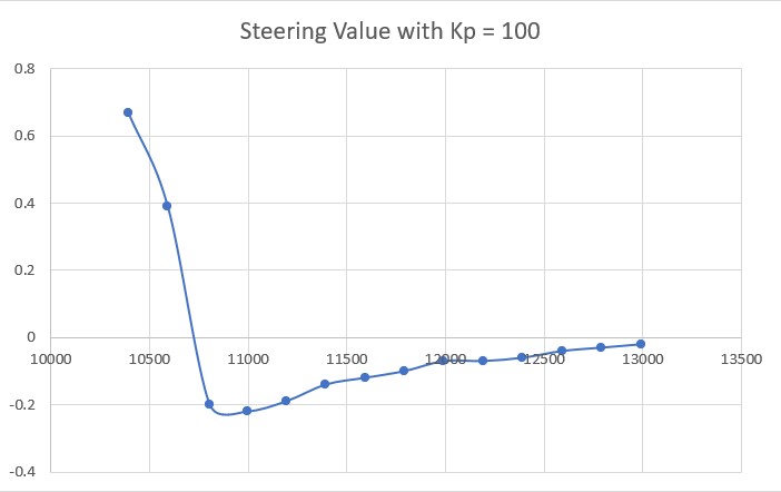
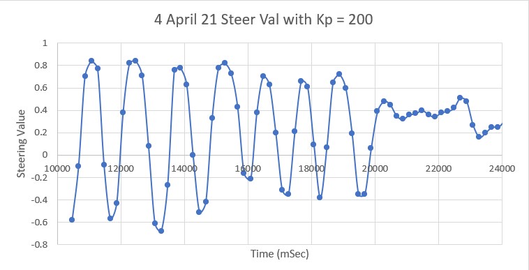
The first step is to determine Kc, the Kp value for which the system oscillates in a reasonably stable fashion. To accomplish this I started with Kp = 20 and worked my way up in stages, plotting the ‘steering value’ each time. The last three trials (as shown in the following plots) were for Kp = 400, Kp = 500 and Kp = 600:
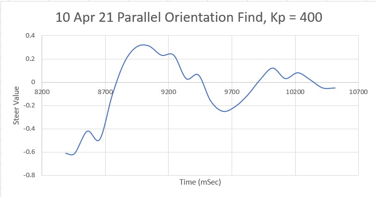
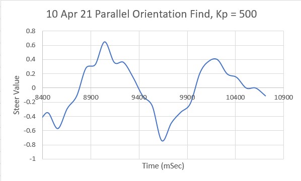
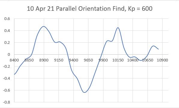
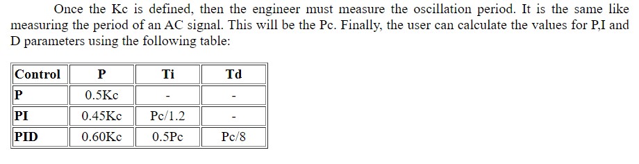
Looking at the above plots, it looks like Kp = 600 will work for Kc. Using the K-N formula, we get
|
1 2 3 |
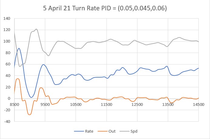
Kp = 0.5Kc = 300 Ki = 0.45Kc = 270 Kd = 0.6Kc = 360 |
Using the above values for the Parallel Find PID, we get the following plot:
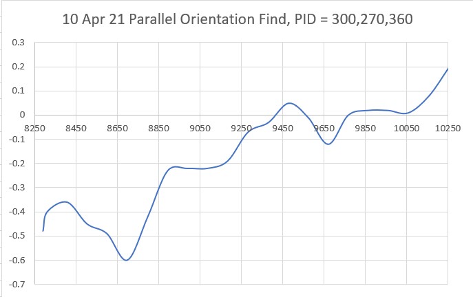
Which is not exactly what I thought it would be – it looks like my guess for Kc must be off. Trying again with a Kc = 400 –> PID = 200,180,240, we get:
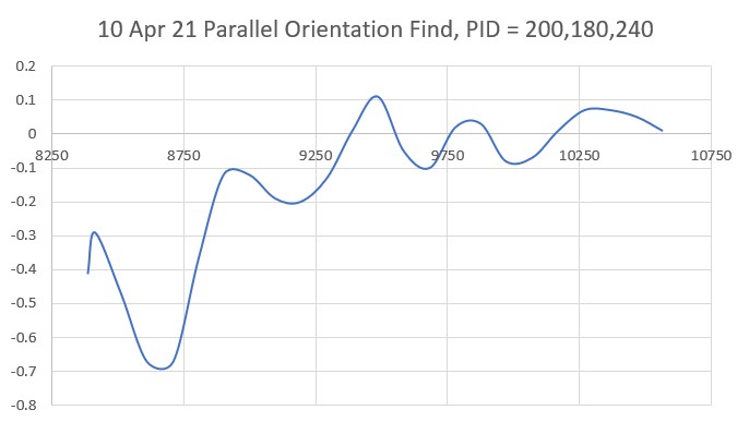
which, to my eye at least, seems a bit better.
To test how this worked with ‘real’ parallel finding, I incorporated these parameter values into my ‘RotateToParallelOrientation()’ routine and ran a couple of tests. Here’s one where Wall-E2 starts in the ‘toed-out’ position:
And here’s the Excel plot from this same run
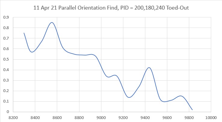
As can be seen, the robot takes less than two seconds to converge on a pretty decent parallel orientation, starting from a 30-40º angle to the near wall.
Here’s another run where the robot starts in the ‘toed-in’ orientation.
And here’s the Excel plot for the run
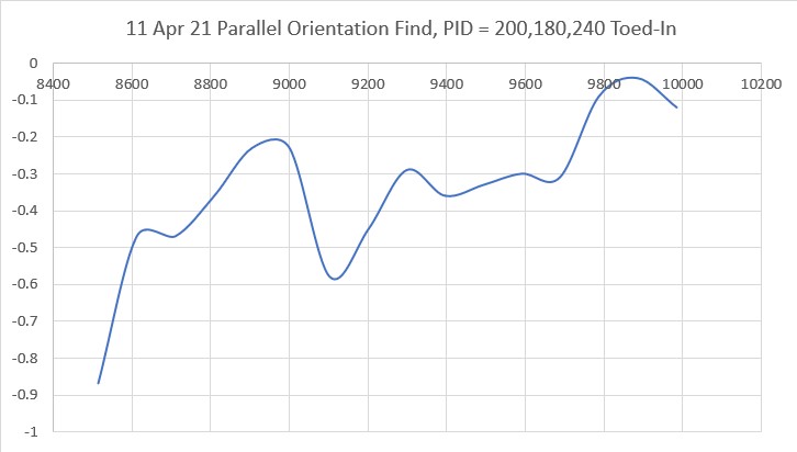
Again, the robot gets to a pretty decent parallel orientation within 2 seconds of the start of the run. The only concern I have with this run is that it winds up pretty close to the wall.