Posted 19 February 2022,
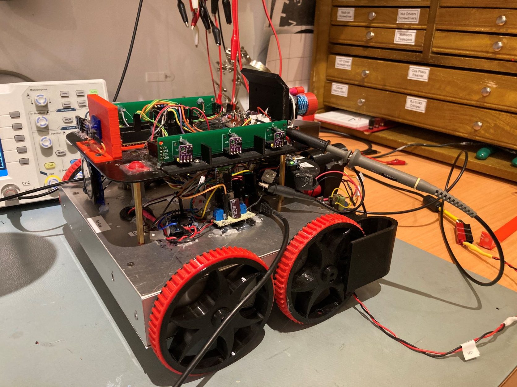
At this point in the evolution of Wall-E3, all the hardware seems to be working, so it’s time to get serious about wall tracking. Last fall I made another run at wall tracking with Wall-E2, and wound up with an algorithm that would first capture the desired wall offset, and then track it ‘forever’. This worked great, but the approach is at odds with the general processing architecture. The current tracking architecture is set up as a loop, where all pertinent parameters are updated every loop period, and the appropriate action is taken. In the case of wall tracking, the ‘action’ was one left/right motor speed update. This allows rapid recognition of, and adaptation to, various ‘error’ conditions, like being stuck or about to run into something. The algorithm developed last fall does none of this, so it can’t react properly (or at all, for that matter) to things like an upcoming wall.
I’m starting to think I can use a hybrid approach – use the current capture/tracking algorithm pretty much as it stands from last fall, but have it check for ‘error’ conditions each time through its own internal loop. If any unusual conditions are detected, then force an exit from the tracking routine and another pass through the main ‘traffic director’ function ‘GetOpMode()’. The updated mode assignment will then percolate back down through loop() and cause the appropriate handling function to be called.
22 February 2022 Update:
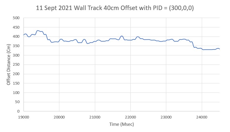
As a start, I ported the ‘TrackLeft/RightWallOffset() functions to Wall-E3 and, after the normal number of screwups and mistakes, I got the left side tracking algorithm working, as shown in the Excel plot and short movie clip below:
Here’s the complete code for ‘TrackLeftWallOffset()’:
|
1 2 3 4 5 6 7 8 9 10 11 12 13 14 15 16 17 18 19 20 21 22 23 24 25 26 27 28 29 30 31 32 33 34 35 36 37 38 39 40 41 42 43 44 45 46 47 48 49 50 51 52 53 54 55 56 57 58 59 60 61 62 63 64 65 66 67 68 69 70 71 72 73 74 75 76 77 78 79 80 81 82 83 84 85 86 87 88 89 90 91 92 93 94 95 96 97 98 99 100 101 102 103 104 105 106 107 108 109 110 111 112 113 114 115 116 117 118 119 120 121 122 123 124 125 126 127 128 129 130 131 132 133 134 135 136 137 138 139 140 141 142 143 144 145 146 147 148 149 150 151 152 153 154 155 156 157 158 159 160 161 162 163 164 165 166 167 168 169 170 171 172 173 174 175 176 177 178 179 180 181 182 183 184 185 186 187 |
void TrackRightWallOffset(float kp, float ki, float kd, float offsetCm) { //Notes: // 06/21/21 modified to do a turn, then straight, then track 0 steer val // 09/12/21 updated from TrackLeftWallOffset // 02/22/22 cleaned up mSecSinceLastWallTrackUpdate = 0; float lastError = 0; float lastInput = 0; float lastIval = 0; float lastDerror = 0; float spinRateDPS = 30; GetRequestedVL53l0xValues(VL53L0X_RIGHT); //update glRightSteeringVal = (Front - Rear)/100 //09/12/21 ported from TrackLeftWallOffset myTeePrint.printf("\nIn TrackRightWallOffset with Kp/Ki/Kd = %2.2f\t%2.2f\t%2.2f\n", kp, ki, kd); //06/21/21 modified to do a turn, then straight, then track 0 steer val float cutAngleDeg = WALL_OFFSET_TGTDIST_CM - (int)(glLidar_RightCenter / 10.f);//positive inside, negative outside desired offset myTeePrint.printf("R/C/F dists = %d\t%d\t%d Steerval = %2.3f, CutAngle = %2.2f\n", glLidar_RightRear, glLidar_RightCenter, glLidar_RightFront, glRightSteeringVal, cutAngleDeg); //07/05/21 implement min cut angle if (cutAngleDeg < 0 && abs(cutAngleDeg) < WALL_OFFSET_APPR_ANGLE_MINDEG) { myTeePrint.printf("(cutAngleDeg < 0 && abs(cutAngleDeg) < %d -- setting to -%d\n", WALL_OFFSET_APPR_ANGLE_MINDEG, WALL_OFFSET_APPR_ANGLE_MINDEG); cutAngleDeg = -WALL_OFFSET_APPR_ANGLE_MINDEG; } else if (cutAngleDeg > 0 && cutAngleDeg < WALL_OFFSET_APPR_ANGLE_MINDEG) { myTeePrint.printf("(cutAngleDeg > 0 && abs(cutAngleDeg) < %d -- setting to +%d\n", WALL_OFFSET_APPR_ANGLE_MINDEG, WALL_OFFSET_APPR_ANGLE_MINDEG); cutAngleDeg = WALL_OFFSET_APPR_ANGLE_MINDEG; } //get the steering angle from the steering value, for comparison to the computed cut angle //positive value means robot is oriented away from wall float SteerAngleDeg = GetSteeringAngle(glRightSteeringVal); myTeePrint.printf("R/C/F dists = %d\t%d\t%d Steerval = %2.3f, SteerAngle = %2.2f, CutAngle = %2.2f\n", glLidar_RightRear, glLidar_RightCenter, glLidar_RightFront, glRightSteeringVal, SteerAngleDeg, cutAngleDeg); //now decide which way to turn. //double adjCutAngleDeg = 0; uint16_t fudgeFactorMM = 0; //07/05/21 added so can change for inside vs outside starting condx if (cutAngleDeg > 0) //robot inside desired offset distance { if (SteerAngleDeg > cutAngleDeg) // --> implies SteerAngleDeg also > 0 { //robot pointed away from wall more than it should myTeePrint.printf("CutAngDeg > 0, SteerAngleDeg > cutAngleDeg\n"); SpinTurn(false, SteerAngleDeg - cutAngleDeg, spinRateDPS); //turn back toward wall to achieve cutAngle } else if (SteerAngleDeg < cutAngleDeg)// --> SteerAngleDeg could be < 0 { //robot not turned far enough away from wall (could actually be turned toward wall if SteerAngDeg < 0) myTeePrint.printf("CutAngDeg > 0, SteerAngleDeg < cutAngleDeg\n"); if (SteerAngleDeg <= 0) //cutAngleDeg > 0, SteerAngleDeg <= 0 { //robot turned toward wall myTeePrint.printf("CutAngDeg > 0, SteerAngleDeg < cutAngleDeg, SteerAngleDeg <= 0\n"); SpinTurn(true, cutAngleDeg + SteerAngleDeg, spinRateDPS); //null out SteerAngleDeg & then turn addnl cutAngleDeg } else //SteerAngleDeg < cutAngleDeg but still > 0 { //robot turned away from wall, but not far enough myTeePrint.printf("CutAngDeg > 0, 0 < SteerAngleDeg < cutAngleDeg\n"); SpinTurn(true, cutAngleDeg - SteerAngleDeg, spinRateDPS); //turn diff between SteerAngleDeg & cutAngleDeg } } fudgeFactorMM = -100; //07/05/21 don't need fudge factor for inside start condx } else // cutAngleDeg < 0 --> robot outside desired offset distance { if (SteerAngleDeg < cutAngleDeg) // --> SteerAngleDeg must also be < 0 { //robot turned too far toward wall myTeePrint.printf("CutAngDeg < 0, SteerAngleDeg < cutAngleDeg\n"); SpinTurn(true, SteerAngleDeg - cutAngleDeg, spinRateDPS); //turn away from wall to achieve cutAngleDeg } else if (SteerAngleDeg >= cutAngleDeg)// --> SteerAngleDeg could be >=0 { if (SteerAngleDeg >= 0) //cutAngleDeg < 0, SteerAngleDeg >= 0 { //robot turned to far away from wall myTeePrint.printf("CutAngDeg < 0, SteerAngleDeg <= 0\n"); SpinTurn(false, cutAngleDeg + SteerAngleDeg, spinRateDPS); //null out SteerAngleDeg & then turn addnl cutAngleDeg } else //SteerAngleDeg > cutAngleDeg but still < 0 { //robot turned toward wall, but not enough myTeePrint.printf("CutAngDeg < 0, 0 < SteerAngleDeg < cutAngleDeg\n"); SpinTurn(false, cutAngleDeg - SteerAngleDeg, spinRateDPS); //turn diff between SteerAngleDeg & cutAngleDeg } } fudgeFactorMM = 100; //07/05/21 need fudge factor for outside start condx } delay(1000); //adjust so offset capture occurs at correct perpendicular offset float adjfactor = cos(PI * cutAngleDeg / 180.f); int adjOffsetMM = (int)(10 * (float)WALL_OFFSET_TGTDIST_CM / adjfactor); adjOffsetMM += fudgeFactorMM; //fudge factor for distance measurements lagging behind robot's travel. myTeePrint.printf("\nat approach start: cut angle = %2.3f, adjfactor = %2.3f, tgt dist = %d\n", cutAngleDeg, adjfactor, adjOffsetMM); GetRequestedVL53l0xValues(VL53L0X_ALL); //added 09/05/21 long int err = glLidar_RightFront - adjOffsetMM; //neg for inside going out, pos for outside going in long int prev_err = err; myTeePrint.printf("At start - err = prev_err = %ld\n", err, prev_err); SteerAngleDeg = GetSteeringAngle(glRightSteeringVal); myTeePrint.printf("R/C/F dists = %d\t%d\t%d Steerval = %2.3f, SteerAngle = %2.2f, CutAngle = %2.2f, err/prev_err = %li\n", glLidar_RightRear, glLidar_RightCenter, glLidar_RightFront, glRightSteeringVal, SteerAngleDeg, cutAngleDeg, err); myTeePrint.printf("Msec\tRFront\tRCtr\tRRear\tFront\tRear\tErr\tP_err\n"); //09/05/21 rev to doublecheck robot position - might not need the forward motion section while (((cutAngleDeg > 0 && err < 0) || (cutAngleDeg <= 0 && err >= 0)) && prev_err * err > 0) //sign change makes this < 0 { prev_err = err; MoveAhead(MOTOR_SPEED_QTR, MOTOR_SPEED_QTR); delay(100); glFrontdistval = GetFrontDistCm(); GetRequestedVL53l0xValues(VL53L0X_RIGHT); err = glLidar_RightFront - adjOffsetMM; //06/29/21 now adj for slant dist vs perp dist myTeePrint.printf("%lu\t%d\t%d\t%d\t%d\t%d\t%ld\t%ld\n", millis(), glLidar_RightFront, glLidar_RightCenter, glLidar_RightRear, glFrontdistval, glLidar_Rear, err, prev_err); CheckForUserInput(); } //now turn back the same (unadjusted) amount myTeePrint.printf("At end of offset capture - prev_res*res = %ld\n", prev_err * err); myTeePrint.printf("correct back to parallel\n"); SpinTurn((cutAngleDeg < 0), abs(cutAngleDeg), spinRateDPS); //have to use abs() here, as cutAngleDeg can be neg WallTrackSetPoint = 0; //moved here 6/22/21 myTeePrint.printf("\nTrackRightWallOffset: Start tracking offset of %2.2fcm with Kp/Ki/Kd = %2.2f\t%2.2f\t%2.2f\n", offsetCm, kp, ki, kd); myTeePrint.printf("Msec\tFdir\tCdir\tRdir\tSteer\tSet\terror\tIval\tKp*err\tKi*Ival\tKd*Din\tOutput\tLspd\tRspd\n"); mSecSinceLastWallTrackUpdate = 0; //added 09/04/21 while (true) { CheckForUserInput(); //this is a bit recursive, but should still work (I hope) if (mSecSinceLastWallTrackUpdate > WALL_TRACK_UPDATE_INTERVAL_MSEC) { mSecSinceLastWallTrackUpdate -= WALL_TRACK_UPDATE_INTERVAL_MSEC; GetRequestedVL53l0xValues(VL53L0X_RIGHT); //now done in TIMER5 ISR //have to weight value by both angle and wall offset WallTrackSteerVal = glRightSteeringVal + (glLidar_RightCenter - 10 * WALL_OFFSET_TGTDIST_CM) / 250.f; //update motor speeds, skipping bad values if (!isnan(WallTrackSteerVal)) { WallTrackOutput = PIDCalcs(WallTrackSteerVal, WallTrackSetPoint, lastError, lastInput, lastIval, lastDerror, kp, ki, kd); int glLeftspeednum = MOTOR_SPEED_QTR - WallTrackOutput; int glRightspeednum = MOTOR_SPEED_QTR + WallTrackOutput; glRightspeednum = (glRightspeednum <= MOTOR_SPEED_FULL) ? glRightspeednum : MOTOR_SPEED_FULL; glRightspeednum = (glRightspeednum > 0) ? glRightspeednum : 0; glLeftspeednum = (glLeftspeednum <= MOTOR_SPEED_FULL) ? glLeftspeednum : MOTOR_SPEED_FULL; glLeftspeednum = (glLeftspeednum > 0) ? glLeftspeednum : 0; MoveAhead(glLeftspeednum, glRightspeednum); myTeePrint.printf("%lu \t%d\t%d\t%d \t%2.2f\t%2.2f\t%2.2f\t%2.2f \t%2.2f\t%2.2f\t%2.2f \t%2.2f\t%d\t%d\n", millis(), glLidar_RightFront, glLidar_RightCenter, glLidar_RightRear, WallTrackSteerVal, WallTrackSetPoint, lastError, lastIval, kp * lastError, ki * lastIval, kd * lastDerror, WallTrackOutput, glLeftspeednum, glRightspeednum); } } } } |
The above algorithm works great, but it runs in an infinite loop once it has captured the wall offset. Based on my above comments about a hybrid approach, I could add tests for stuck and/or front or back obstacles to this loop (instead of the current ‘while(true)’). This would cause TrackLeftWallOffset() to exit, and the GetOpMode() function could assign the appropriate mode, which would then cause the proper function to execute.
Or, I could eliminate GetOpMode() entirely and put it’s logic in ‘loop()’? Actually, looking at the loop() function in FourWD_WallE2_V12.ino, my last iteration with the Arduino Mega2560, I see that GetOpMode() is called at the start of loop(), and then the OpMode switch statement comes pretty much immediately afterwards. Here’s the code:
|
1 2 3 4 5 6 7 8 9 10 11 12 13 14 15 16 17 18 19 20 21 22 23 24 25 26 27 28 29 30 31 32 33 34 35 36 37 38 39 40 41 42 43 44 45 46 47 48 49 50 51 52 53 54 55 56 57 58 59 60 61 62 63 64 65 66 67 68 69 70 71 72 73 74 75 76 77 78 79 80 81 82 83 84 85 86 87 88 89 90 91 92 93 94 95 96 97 98 99 100 101 102 103 104 105 106 107 108 109 110 111 112 113 114 115 116 117 118 119 120 121 122 123 124 125 126 127 128 129 130 131 132 133 134 135 136 137 138 139 140 141 142 143 144 145 146 147 148 149 150 151 152 153 154 155 156 157 158 159 160 161 162 163 164 165 166 167 168 169 170 171 172 173 174 175 176 177 178 179 180 181 182 183 184 185 186 187 188 189 190 191 192 193 194 195 196 197 198 199 200 201 202 203 204 205 206 207 208 209 210 211 212 213 214 215 216 217 218 219 220 221 222 223 224 225 226 227 228 229 230 231 232 233 234 235 236 237 238 239 240 241 242 243 244 245 246 247 248 249 250 251 252 253 254 255 256 257 258 259 260 261 262 263 264 265 266 267 268 269 270 271 272 273 274 275 276 277 278 279 280 281 282 283 284 285 286 287 288 289 290 291 292 293 294 295 296 297 298 299 300 301 302 303 304 305 306 307 308 309 310 311 312 313 314 315 316 317 318 319 320 321 322 323 324 325 326 327 328 329 330 331 332 333 334 335 336 337 338 339 340 341 342 343 344 345 346 347 348 349 350 351 352 353 354 355 356 357 358 359 360 361 362 363 364 365 366 367 368 369 370 371 372 373 374 375 376 377 378 379 380 381 382 383 384 385 386 387 388 389 390 391 392 393 394 395 396 397 398 399 400 401 402 403 404 405 406 407 408 409 410 411 412 413 414 415 416 417 418 419 420 421 422 423 424 425 426 427 428 429 430 431 432 433 434 435 436 437 438 439 440 441 442 443 444 445 446 447 448 449 450 451 452 453 454 455 456 457 458 459 460 461 462 463 464 465 466 467 468 469 470 471 472 473 474 475 476 477 478 479 480 481 482 483 484 485 486 487 488 489 490 |
void loop() { CheckForUserInput(); //allows remote manual robot control //03/08/17 Revised to introduce three top-level op modes (wall-follow, IR home, charging) //Purpose: Follow nearest wall, or home on IR beam, or monitor charging as necessary //Plan: // Step1: Determine current operating mode // Step2: Switch to appropriate operating case block // Step3: Check for FRAM and/or MPU interrupt flags //Notes: // 03/19/17 IRHomeToChgStn sig rev to include init l/r speeds in IRHOMING case block // 09/19/18 added section to write telemetry to FRAM // 08/15/20 new plan: use 'bTimeForNavUpdate' set to true in Timer ISR, cleared here // 08/15/20 new plan: use 'bTimeForNavUpdate' set to true in Timer1 ISR, cleared here if (bTimeForNavUpdate) { //mySerial.printf("%lu: Top of Loop()\n", millis()); bTimeForNavUpdate = false; //set in Timer1 ISR digitalWrite(RED_LASER_DIODE_PIN, HIGH); //fire the laser pointer //03/10/19 rev so NO_STUCK #define can prevent 'stuck' detection while still keeping LIDAR active #ifndef NO_LIDAR //frontdistval = GetFrontDistCm(); //11/02/20 frontdistval updated in ISR #else frontdistval = MAX_FRONT_DISTANCE_CM; //05/03/17 bugfix #endif //NO_LIDAR UpdateLRDistanceArrays(Lidar_LeftCenter, Lidar_RightCenter); float batVoltage = GetBattVoltage(); //04/28/19 mvd here so can be used in GetOpMode() CurrentOpMode = (OpModes)GetOpMode(batVoltage); //04/28/19 bat volts added to sig //Step1: Determine current operating mode #pragma region OP_MODE SWITCH //Step2: Switch to appropriate operating case block String trackstr = "Unknown"; //used for telemetry printouts switch (CurrentOpMode) { #pragma region MODE_CHARGING case MODE_CHARGING: digitalWrite(RED_LASER_DIODE_PIN, LOW); //disable the laser pointer chgStartMsec = millis(); //used for charge duration telemetry Serial.print(F("Starting Charge Mode at ")); Serial.println(chgStartMsec); StopBothMotors(); //added 03/13/17 //04/27/21 mySerial.printf("Reset VL53L0X Teensy to reduce current consumption\n"); digitalWrite(VL53L0X_TEENSY_RESET_PIN, LOW); //hold Teensy reset to reduce current consumption MonitorChargeUntilDone(); mySerial.printf("Restart VL53L0X Teensy...\n"); digitalWrite(VL53L0X_TEENSY_RESET_PIN, HIGH); //restart Teensy WaitForVL53L0XTeensy(); //wait for it to come back up. ExecDisconManeuver(); PrevOpMode = MODE_NONE; //04/27/21: this will force wall offset recapture //mySerial.printf("%lu: just after ExecDisconManeuver() in TRACKING_RIGHT case block\n", millis()); break; #pragma endregion MODE_CHARGING #pragma region MODE_IRHOMING case MODE_IRHOMING: digitalWrite(RED_LASER_DIODE_PIN, LOW); //disable the laser pointer mySerial.printf("IR Beam Detected with Battery Voltage = %1.2f\n", batVoltage); //PrevOpMode = MODE_IRHOMING; if (batVoltage > LOW_BATT_THRESH_VOLTS) //not hungry { Serial.println("Not Hungry - Avoiding Charger"); //04/27/21 too complicated - just have robot reverse course int leftdist = GetAvgLeftDistCm(); int rightdist = GetAvgRightDistCm(); SpinTurn(leftdist > rightdist, 180); PrevOpMode = MODE_NONE; } else //hungry - try to connect { Serial.println("Low battery - homing to Charger"); IRHomeToChgStn(0, MOTOR_SPEED_HALF, MOTOR_SPEED_HALF); } break; #pragma endregion IR Homing Case #pragma region MODE_WALLFOLLOW case MODE_WALLFOLLOW: //Purpose: Follow nearest wall, responding to obstacles as necessary //Provenance: G. Frank Paynter and Danny Frank 12/20/2015 //Inputs: Distances from left/right/front sensors //Outputs: updated left/right motor speeds in wall-follow case, or appropriate avoidance maneuver //Plan: // Step 1: Update motor speeds & NAV mode based on current TRACK/NAV states and front distance // Step 2: Print out telemetry info //Notes: // 03/30/14 Step1 code moved to top of loop() - compiler directives cause errors here // 09/11/18 revised plan to reflect reality // 04/11/20 revised to incorporate heading-based wall offset tracking // Update motor speeds & NAV mode based on current TRACK/NAV states and front distance // See https://fpaynter.com/2016/01/making-wall-e2-smarter-using-karnaugh-maps/ for details //11/13/20 rev to use a sliding obstacle detection range during tracking ops //detection range is WALL_OFFSET_TGTDIST_CM/2 at max cut, increasing to WALL_OFFSET_TGTDIST_CM with zero cut angle float adjustedFrontObstacleDetectionRangeCm = (WallTrackSetPoint <= 0) ? WALL_OFFSET_TGTDIST_CM * ((WallTrackSetPoint / (2 * WALL_OFFSET_TRACK_SETPOINT_LIMIT)) + 1) : WALL_OFFSET_TGTDIST_CM; TrackingCase = (WallTrackingCases)GetTrackingDir(); switch (TrackingCase) { case TRACKING_LEFT: #pragma region TRACKLEFT //mySerial.printf("At top of TRACKING_LEFT case block\n"); //07/22/2020 updated to use VL53L0X array vs 'ping' sensors trackstr = "Left"; //used for telemetry printouts //10/08/20 hack to prevent immediate obstacle detection if (PrevOpMode != MODE_WALLFOLLOW) WallTrackSetPoint = -WALL_OFFSET_TRACK_SETPOINT_LIMIT; if (bIsStuck)//bIsStuck updated in timer1 ISR { mySerial.printf("bIsStuck TRUE in TRACKLEFT at %lu with frontdist %d, variance = %6.2f\n", millis(), frontdistval, frontvar); InitFrontDistArray(); //added 08/12/20 to prevent multiple 'stuck' detections ExecuteStuckRecoveryManeuver(TRACKING_LEFT); //10/24/20 PrevOpMode = MODE_NONE; //this will force wall offset recapture WallTrackPID.SetMode(MANUAL); //11/21/20 this will force PID re-init break; //don't execute the rest - just go back to GetOpMode() } //11/11/20 added separate section for 'Obstacle Ahead' if (bObstacleAhead)//bObstacleAhead updated in timer1 ISR { mySerial.printf("bObstacleAhead TRUE in TRACKLEFT at %lu with frontdist %d, variance = %6.2f\n", millis(), frontdistval, frontvar); InitFrontDistArray(); //added 08/12/20 to prevent multiple 'stuck' detections //11/13/20 added code to back up to WALL_OFFSET_TGTDIST_CM before beginning the spin turn mySerial.printf("backing up to %d using front distance sensor\n", WALL_OFFSET_TGTDIST_CM); MoveToDesiredFrontDistCm(WALL_OFFSET_TGTDIST_CM); mySerial.printf("backed up successfully to %d using front distance sensor\n", frontdistval); SpinTurn(false, 90);//turn 90 deg right PrevOpMode = MODE_NONE; //this will force wall offset recapture WallTrackPID.SetMode(MANUAL); //11/21/20 this will force PID re-init break; //don't execute the rest - just go back to GetOpMode() } //11/08/20 added section for too close behind //the idea is to move ahead to a position about WALL_OFFSET_TGTDIST_CM away from wall, and turn 45 deg //one way or other so wall tracking can continue from that point else if (bObstacleBehind) { mySerial.printf("Obstacle behind with reardist, frontdist = %d, %d cm\n", Lidar_Rear / 10, frontdistval); ExecuteRearObstacleRecoveryManeuver(); //doesn't need tracking case info PrevOpMode = MODE_NONE; WallTrackPID.SetMode(MANUAL); //11/21/20 this will force PID re-init break; } //11/13/20 rev to use a sliding obstacle detection range during tracking ops //detection range is WALL_OFFSET_TGTDIST_CM/2 at max cut, increasing to WALL_OFFSET_TGTDIST_CM with zero cut angle else if (frontdistval < adjustedFrontObstacleDetectionRangeCm) { //DEBUG!! mySerial.printf("Hit adjusted wall offset limit (%2.2f cm) at %lu with frontdist = %d, Setpoint = %2.2f\n", adjustedFrontObstacleDetectionRangeCm, millis(), frontdistval, WallTrackSetPoint); //DEBUG!! //06/06/21 rev to use code from 'if (bObstacleAhead)' block ////StepTurn(TRACKING_LEFT); //PrevOpMode = MODE_NONE; //this will force wall offset recapture //WallTrackPID.SetMode(MANUAL); //11/21/20 this will force PID re-init InitFrontDistArray(); //added 08/12/20 to prevent multiple 'stuck' detections //11/13/20 added code to back up to WALL_OFFSET_TGTDIST_CM before beginning the spin turn mySerial.printf("backing up to %d using front distance sensor\n", WALL_OFFSET_TGTDIST_CM); MoveToDesiredFrontDistCm(WALL_OFFSET_TGTDIST_CM); mySerial.printf("backed up successfully to %d using front distance sensor\n", frontdistval); SpinTurn(false, 90);//turn 90 deg right PrevOpMode = MODE_NONE; //this will force wall offset recapture WallTrackPID.SetMode(MANUAL); //11/21/20 this will force PID re-init break; //don't execute the rest - just go back to GetOpMode() } //if we get to here, not stuck and no nearby obstacle issues else if (PrevOpMode != MODE_WALLFOLLOW)//02/26/20 first time through capture offset { PrevOpMode = MODE_WALLFOLLOW; //added 04/27/21 //04/18/21 experiment with IRHomingNavigateToIAP() here RotateToParallelOrientation(TRACKING_LEFT); if (bIRBeamAvail) { IRHomingNavigateToIAP(TRACKING_LEFT); if (batVoltage > LOW_BATT_THRESH_VOLTS) //not hungry { Serial.println("Not Hungry - Avoiding Charger"); curMinObstacleDistance = CHG_STN_AVOIDANCE_DIST_CM; //hopefully this will cause avoidance IRHomeToChgStn(CHG_STN_AVOIDANCE_DIST_CM, MOTOR_SPEED_HALF, MOTOR_SPEED_HALF); } else //hungry - try to connect { Serial.println("Low battery - homing to Charger"); IRHomeToChgStn(0, MOTOR_SPEED_HALF, MOTOR_SPEED_HALF); StopBothMotors(); digitalWrite(RED_LASER_DIODE_PIN, LOW); //turn off the laser mySerial.printf("Reset VL53L0X Teensy to reduce current consumption\n"); digitalWrite(VL53L0X_TEENSY_RESET_PIN, LOW); //hold Teensy reset to reduce current consumption MonitorChargeUntilDone(); mySerial.printf("Restart VL53L0X Teensy...\n"); digitalWrite(VL53L0X_TEENSY_RESET_PIN, HIGH); //restart Teensy WaitForVL53L0XTeensy(); //wait for it to come back up. ExecDisconManeuver(); PrevOpMode = MODE_NONE; //this will force wall offset recapture mySerial.printf("%lu: just after ExecDisconManeuver() in TRACKING_LEFT case block\n", millis()); break; } } } //if we get here, we are continuing tracking operation PrevOpMode = MODE_WALLFOLLOW; //added 04/27/21 WallTrackSteerVal = LeftSteeringVal; //computed by Teensy 3.5 //at 30mm from tgt offset, setpoint will be +/-0.3 WallTrackSetPoint = (double)(10 * WALL_OFFSET_TGTDIST_CM - Lidar_LeftCenter) / 100.f; //10/04/20 positive value drives robot toward wall //limit approach angle to reasonable values if (WallTrackSetPoint > WALL_OFFSET_TRACK_SETPOINT_LIMIT) WallTrackSetPoint = WALL_OFFSET_TRACK_SETPOINT_LIMIT; if (WallTrackSetPoint < -WALL_OFFSET_TRACK_SETPOINT_LIMIT) WallTrackSetPoint = -WALL_OFFSET_TRACK_SETPOINT_LIMIT; //update motor speeds, skipping bad values if (!isnan(WallTrackSteerVal)) { //10/12/20 now this executes every time, with interval controlled by timer ISR WallTrackPID.Compute(); leftspeednum = MOTOR_SPEED_QTR - WallTrackOutput; rightspeednum = MOTOR_SPEED_QTR + WallTrackOutput; rightspeednum = (rightspeednum <= MOTOR_SPEED_FULL) ? rightspeednum : MOTOR_SPEED_FULL; rightspeednum = (rightspeednum > 0) ? rightspeednum : 0; leftspeednum = (leftspeednum <= MOTOR_SPEED_FULL) ? leftspeednum : MOTOR_SPEED_FULL; leftspeednum = (leftspeednum > 0) ? leftspeednum : 0; MoveAhead(leftspeednum, rightspeednum); mySerial.printf("%lu\t%d\t%d\t%d\t%d\t%8.2f\t%d\t%2.2f\t%2.2f\t%2.2f\t%2.2f\t%d\t%d\t%lu\t%2.3f\n", millis(), Lidar_LeftFront, Lidar_LeftCenter, Lidar_LeftRear, frontdistval, frontvar, Lidar_Rear, WallTrackSteerVal, WallTrackOutput, WallTrackSetPoint, adjustedFrontObstacleDetectionRangeCm, leftspeednum, rightspeednum, IRHomingValTotalAvg, IRHomingLRSteeringVal); } #pragma endregion Tracking Left Wall Case //mySerial.printf("At bottom of TRACKING_LEFT case block\n"); break; case TRACKING_RIGHT: #pragma region TRACKRIGHT mySerial.printf("At top of TRACKING_RIGHT case block\n"); //07/22/2020 updated to use VL53L0X array vs 'ping' sensors trackstr = "Right"; //used for telemetry printouts //10/08/20 hack to prevent immediate obstacle detection if (PrevOpMode != MODE_WALLFOLLOW) WallTrackSetPoint = -WALL_OFFSET_TRACK_SETPOINT_LIMIT; if (bIsStuck)//bIsStuck updated in timer1 ISR { mySerial.printf("bIsStuck TRUE in TRACKRIGHT at %lu with frontdist %d, variance = %6.2f\n", millis(), frontdistval, frontvar); InitFrontDistArray(); //added 08/12/20 to prevent multiple 'stuck' detections ExecuteStuckRecoveryManeuver(TRACKING_RIGHT); //10/24/20 PrevOpMode = MODE_NONE; //this will force wall offset recapture WallTrackPID.SetMode(MANUAL); //11/21/20 this will force PID re-init break; //don't execute the rest - just go back to GetOpMode() } //11/11/20 added separate section for 'Obstacle Ahead' if (bObstacleAhead)//bObstacleAhead updated in timer1 ISR { mySerial.printf("bObstacleAhead TRUE in TRACKRIGHT at %lu with frontdist %d, variance = %6.2f\n", millis(), frontdistval, frontvar); InitFrontDistArray(); //added 08/12/20 to prevent multiple 'stuck' detections //11/13/20 added code to back up to WALL_OFFSET_TGTDIST_CM before beginning the spin turn mySerial.printf("backing up to %d using front distance sensor\n", WALL_OFFSET_TGTDIST_CM); MoveToDesiredFrontDistCm(WALL_OFFSET_TGTDIST_CM); mySerial.printf("backed up successfully to %d using front distance sensor\n", frontdistval); SpinTurn(true, 90);//turn 90 deg left PrevOpMode = MODE_NONE; //this will force wall offset recapture WallTrackPID.SetMode(MANUAL); //11/21/20 this will force PID re-init break; //don't execute the rest - just go back to GetOpMode() } //11/08/20 added section for too close behind //the idea is to move ahead to a position about WALL_OFFSET_TGTDIST_CM away from wall, and turn 45 deg //one way or other so wall tracking can continue from that point else if (bObstacleBehind) { mySerial.printf("Obstacle behind with reardist, frontdist = %d, %d cm\n", Lidar_Rear / 10, frontdistval); ExecuteRearObstacleRecoveryManeuver(); //doesn't need tracking case info PrevOpMode = MODE_NONE; WallTrackPID.SetMode(MANUAL); //11/21/20 this will force PID re-init break; } //11/13/20 rev to use a sliding obstacle detection range during tracking ops //detection range is WALL_OFFSET_TGTDIST_CM/2 at max cut, increasing to WALL_OFFSET_TGTDIST_CM with zero cut angle else if (frontdistval < adjustedFrontObstacleDetectionRangeCm) { //DEBUG!! mySerial.printf("Hit adjusted wall offset limit (%2.2f cm) at %lu with frontdist = %d, Setpoint = %2.2f\n", adjustedFrontObstacleDetectionRangeCm, millis(), frontdistval, WallTrackSetPoint); //DEBUG!! //06/06/21 rev to use code from 'if (bObstacleAhead)' block //StepTurn(TRACKING_RIGHT); //PrevOpMode = MODE_NONE; //this will force wall offset recapture //WallTrackPID.SetMode(MANUAL); //11/21/20 this will force PID re-init InitFrontDistArray(); //added 08/12/20 to prevent multiple 'stuck' detections //11/13/20 added code to back up to WALL_OFFSET_TGTDIST_CM before beginning the spin turn mySerial.printf("backing up to %d using front distance sensor\n", WALL_OFFSET_TGTDIST_CM); MoveToDesiredFrontDistCm(WALL_OFFSET_TGTDIST_CM); mySerial.printf("backed up successfully to %d using front distance sensor\n", frontdistval); SpinTurn(true, 90);//turn 90 deg left PrevOpMode = MODE_NONE; //this will force wall offset recapture WallTrackPID.SetMode(MANUAL); //11/21/20 this will force PID re-init break; //don't execute the rest - just go back to GetOpMode() } //if we get to here, not stuck and no nearby obstacle issues else if (PrevOpMode != MODE_WALLFOLLOW)//02/26/20 first time through capture offset { //04/18/21 experiment with IRHomingNavigateToIAP() here RotateToParallelOrientation(TRACKING_RIGHT); if (bIRBeamAvail) { IRHomingNavigateToIAP(TRACKING_RIGHT); if (batVoltage > LOW_BATT_THRESH_VOLTS) //not hungry { Serial.println("Not Hungry - Avoiding Charger"); curMinObstacleDistance = CHG_STN_AVOIDANCE_DIST_CM; //hopefully this will cause avoidance IRHomeToChgStn(CHG_STN_AVOIDANCE_DIST_CM, MOTOR_SPEED_HALF, MOTOR_SPEED_HALF); } else //hungry - try to connect { Serial.println("Low battery - homing to Charger"); IRHomeToChgStn(0, MOTOR_SPEED_HALF, MOTOR_SPEED_HALF); StopBothMotors(); digitalWrite(RED_LASER_DIODE_PIN, LOW); //turn off the laser mySerial.printf("Reset VL53L0X Teensy to reduce current consumption\n"); digitalWrite(VL53L0X_TEENSY_RESET_PIN, LOW); //hold Teensy reset to reduce current consumption MonitorChargeUntilDone(); mySerial.printf("Restart VL53L0X Teensy...\n"); digitalWrite(VL53L0X_TEENSY_RESET_PIN, HIGH); //restart Teensy WaitForVL53L0XTeensy(); //wait for it to come back up. ExecDisconManeuver(); PrevOpMode = MODE_NONE; //04/27/21: this will force wall offset recapture mySerial.printf("%lu: just after ExecDisconManeuver() in TRACKING_RIGHT case block\n", millis()); break; } } } mySerial.printf("After else if (PrevOpMode != MODE_WALLFOLLOW) block\n"); //mySerial.printf("%lu: just after else if (PrevOpMode != MODE_WALLFOLLOW)\n"); //if we get here, we are continuing tracking operation PrevOpMode = MODE_WALLFOLLOW; //added 04/27/21 WallTrackSteerVal = RightSteeringVal; //computed by Teensy 3.5 //at 30mm from tgt offset, setpoint will be +/-0.3 WallTrackSetPoint = (double)(10 * WALL_OFFSET_TGTDIST_CM - Lidar_RightCenter) / 100.f; //10/04/20 positive value drives robot toward wall //limit approach angle to reasonable values if (WallTrackSetPoint > WALL_OFFSET_TRACK_SETPOINT_LIMIT) WallTrackSetPoint = WALL_OFFSET_TRACK_SETPOINT_LIMIT; if (WallTrackSetPoint < -WALL_OFFSET_TRACK_SETPOINT_LIMIT) WallTrackSetPoint = -WALL_OFFSET_TRACK_SETPOINT_LIMIT; //update motor speeds, skipping bad values if (!isnan(WallTrackSteerVal)) { //10/12/20 now this executes every time, with interval controlled by timer ISR WallTrackPID.Compute(); leftspeednum = MOTOR_SPEED_QTR + WallTrackOutput; rightspeednum = MOTOR_SPEED_QTR - WallTrackOutput; rightspeednum = (rightspeednum <= MOTOR_SPEED_FULL) ? rightspeednum : MOTOR_SPEED_FULL; rightspeednum = (rightspeednum > 0) ? rightspeednum : 0; leftspeednum = (leftspeednum <= MOTOR_SPEED_FULL) ? leftspeednum : MOTOR_SPEED_FULL; leftspeednum = (leftspeednum > 0) ? leftspeednum : 0; MoveAhead(leftspeednum, rightspeednum); mySerial.printf("%lu\t%d\t%d\t%d\t%d\t%6.2f\t%2.2f\t%2.2f\t%2.2f\t%2.2f\t%d\t%d\t%lu\t%2.3f\n", millis(), Lidar_RightFront, Lidar_RightCenter, Lidar_RightRear, frontdistval, frontvar, WallTrackSteerVal, WallTrackOutput, WallTrackSetPoint, adjustedFrontObstacleDetectionRangeCm, leftspeednum, rightspeednum, IRHomingValTotalAvg, IRHomingLRSteeringVal); } #pragma endregion Tracking Right Wall Case //mySerial.printf("End of Tracking Right Wall Case\n"); break; case TRACKING_NEITHER: #pragma region TRACKNEITHER trackstr = "Neither"; //used for telemetry printouts mySerial.printf("time(ms) in TRACKNEITHER = %lu\n", millis()); //added 01/20/16: turn direction arbitrary if (bObstacleAhead || bIsStuck) //08/10/20 now bObstacleAhead & bIsStuck updated in timer1 ISR { if (bIsStuck) { InitFrontDistArray(); //added 08/12/20 to prevent multiple 'stuck' detections } //DEBUG!! Serial.println(F("---- Backup & Turn to the Left")); //DEBUG!! BackupAndTurn90Deg(true, true, MOTOR_SPEED_HALF); //go back to normal tracking mode after B&T completes NavCase = NAV_WALLTRK; } //Open Corner case else if (frontdistval > STEPTURN_DIST_CM) { //OK, this is the Open Corner case - turn toward the last-tracked wall #ifndef NO_MOTORS delay(1000); //01/20/16 - delay to give Wall-E2 time to clear the corner a bit #endif if (PrevTrackingCase == TRACKING_LEFT) { //RotateCWDeg(false, NUM_DEG_FOR_90_DEG_TURN, MOTOR_SPEED_HALF); } else if (PrevTrackingCase == TRACKING_RIGHT) { //RotateCWDeg(true, NUM_DEG_FOR_90_DEG_TURN, MOTOR_SPEED_HALF); } else //oops! not tracking either wall - out in middle of room somewhere? { //not open corner, but not tracking a wall, either - go straight leftspeednum = rightspeednum = MOTOR_SPEED_HALF; MoveAhead(leftspeednum, rightspeednum); } } #pragma endregion Not Tracking Either Wall break; default: break; //mySerial.printf("Bottom of opMode switch\n"); } //switch (TrackingCase) #pragma endregion MODE_WALLFOLLOW //mySerial.printf("%lu: at end of MODE_WALLFOLLOW\n", millis()); //07/16/21 added to manage offset capture operation #pragma region MODE_WALLCAPTURE case MODE_WALLCAPTURE: break; #pragma endregion MODE_WALLCAPTURE } digitalWrite(RED_LASER_DIODE_PIN, LOW); //mySerial.printf("%lu: Bottom of loop()\n", millis()); }//if (bTimeForNavUpdate) }//loop() |
The MODE_CHARGING and MODE_HOMING cases are self-contained, so no changes would be needed for them. The MODE_WALLFOLLOW case is sub-divided into TRACKING_LEFT and TRACKING_RIGHT cases. If all the inline code in TRACKING_LEFT was replaced with TrackLeftWallOffset() and that of TRACKING_RIGHT with TrackRightWallOffset(), with these two functions augmented by the current if (bIsStuck) , if(bObstacleAhead) and if(bObstacleBehind) guard code (pretty much as it now stands), then that should work. I think I’ll give that whirl and see what happens.
To start the process, I created yet another project – WallE3_WallTrack_V3 (to preserve the currently ‘working OK on left side’ status of WallE3_WallTrack_V2) and try porting the GetOpMode() and loop() code from FourWD_WallE2_V12.
02 March 2022 Update:
I now have a ‘loop() only’ version of WallE3 running that properly tracks the left side. Everything is basically the same as before, except the loop() function, shown below:
|
1 2 3 4 5 6 7 8 9 10 11 12 13 14 15 16 17 18 19 20 21 22 23 24 25 26 27 28 29 30 31 32 33 34 35 36 37 38 39 40 41 42 43 44 45 46 47 48 49 50 51 52 53 54 55 56 57 58 59 60 61 62 63 64 65 66 |
void loop() { CheckForUserInput(); #pragma region IR HOMING UpdateIRHomingValues(); //update all IR Homing related values bool bIRBeamAvail = (IRHomingValTotalAvg > IR_BEAM_DETECTION_THRESHOLD && abs(IRHomingLRSteeringVal) < IR_HOMING_STEERING_VAL_DETECTION_THRESHOLD); if (bIRBeamAvail) { digitalWrite(RED_LASER_DIODE_PIN, LOW); //disable the laser pointer float batVoltage = GetBattVoltage(); myTeePrint.printf("IR Beam Detected with Battery Voltage = %1.2f\n", batVoltage); if (batVoltage > LOW_BATT_THRESH_VOLTS) //not hungry { Serial.println("Not Hungry - Avoiding Charger"); //04/27/21 too complicated - just have robot reverse course int leftdist = GetAvgLeftDistCm(); int rightdist = GetAvgRightDistCm(); SpinTurn(leftdist > rightdist, 180); } else //hungry - try to connect { Serial.println("Low battery - homing to Charger"); IRHomeToChgStn(0, MOTOR_SPEED_HALF, MOTOR_SPEED_HALF); } } #pragma endregion IR HOMING #pragma region CHARGING if (IsChargerConnected()) { myTeePrint.printf("Robot has successfully connected to charger!\n"); digitalWrite(RED_LASER_DIODE_PIN, LOW); //disable the laser pointer chgStartMsec = millis(); //used for charge duration telemetry Serial.print(F("Starting Charge Mode at ")); Serial.println(chgStartMsec); StopBothMotors(); //added 03/13/17 //04/27/21 myTeePrint.printf("Reset VL53L0X Teensy to reduce current consumption\n"); digitalWrite(VL53L0X_TEENSY_RESET_PIN, LOW); //hold Teensy reset to reduce current consumption MonitorChargeUntilDone(); myTeePrint.printf("Restart VL53L0X Teensy...\n"); digitalWrite(VL53L0X_TEENSY_RESET_PIN, HIGH); //restart Teensy WaitForVL53L0XTeensy(); //wait for it to come back up. ExecDisconManeuver(); } #pragma endregion CHARGING #pragma region WALL TRACKING UpdateAllDistances(); if (glLeftCenterCm <= glRightCenterCm) { TrackLeftWallOffset(); //parameterless overload } else if (glLeftCenterCm > glRightCenterCm) { TrackRightWallOffset(); //parameterless overload } #pragma endregion WALL TRACKING } |
The ‘IR HOMING’ and ‘CHARGING’ blocks are essentially unchanged, and the ‘WALL TRACKING’ block is much simpler. All ‘anomaly’ (robot stuck either forward or backward, robot approaching an obstacle ahead or behind, dead battery, etc are all handled internally to the two ‘TrackLeft/RightWallOffset()’ functions. Here’s the (potentially infinite) ‘while()’ loop:
|
1 2 3 4 5 6 7 8 9 10 11 12 13 14 15 16 17 18 19 20 21 22 23 24 25 26 27 28 29 30 31 32 33 34 35 36 37 38 39 40 41 42 43 |
while (errcode == NO_ANOMALIES) { CheckForUserInput(); //this is a bit recursive, but should still work (I hope) //09/04/21 back to elapsedMillis timing if (mSecSinceLastWallTrackUpdate > WALL_TRACK_UPDATE_INTERVAL_MSEC) { mSecSinceLastWallTrackUpdate -= WALL_TRACK_UPDATE_INTERVAL_MSEC; UpdateAllDistances(); //need to update ALL distances to detect stuck conditions CheckForErrorCondx(); //have to weight value by both angle and wall offset //WallTrackSteerVal = glLeftSteeringVal + (glLeftCenterCm - 10 * WALL_OFFSET_TGTDIST_CM) / 1000.f; WallTrackSteerVal = glLeftSteeringVal + (glLeftCenterCm - WALL_OFFSET_TGTDIST_CM) / 1000.f; //update motor speeds, skipping bad values if (!isnan(WallTrackSteerVal)) { //02/05/22 sampleTime removed from signature WallTrackOutput = PIDCalcs(WallTrackSteerVal, WallTrackSetPoint, lastError, lastInput, lastIval, lastDerror, kp, ki, kd); int glLeftspeednum = MOTOR_SPEED_QTR + WallTrackOutput; int glRightspeednum = MOTOR_SPEED_QTR - WallTrackOutput; glRightspeednum = (glRightspeednum <= MOTOR_SPEED_FULL) ? glRightspeednum : MOTOR_SPEED_FULL; glRightspeednum = (glRightspeednum > 0) ? glRightspeednum : 0; glLeftspeednum = (glLeftspeednum <= MOTOR_SPEED_FULL) ? glLeftspeednum : MOTOR_SPEED_FULL; glLeftspeednum = (glLeftspeednum > 0) ? glLeftspeednum : 0; MoveAhead(glLeftspeednum, glRightspeednum); myTeePrint.printf("%lu \t%d\t%d\t%d\t%d\t%2.2f\t%2.2f\t%2.2f\t%2.2f \t%2.2f\t%2.2f\t%2.2f \t%2.2f\t%d\t%d\n", millis(), glLeftFrontCm, glLeftCenterCm, glLeftRearCm, glRearCm, WallTrackSteerVal, WallTrackSetPoint, lastError, lastIval, kp * lastError, ki * lastIval, kd * lastDerror, WallTrackOutput, glLeftspeednum, glRightspeednum); } } } |
As the code above shows, the while loop will continue to execute as long as the ‘errcode’ value is ‘NO_ANOMALIES’. Internally the ‘CheckForErrorCondx()’ function surveys the inputs from all sensors and attempts to detect any anomalous behavior. Any return value except NO_ANOMALIES causes the while() loop to exit. Each potential anomaly condition has its own handling function, which exits back to ‘loop()’ and the process starts all over again. I believe this is a much cleaner approach than I had before with the ‘GetOpMode()’ function.
I also took the opportunity at this point to fix a long-standing problem with the code. The front-facing LIDAR unit returns distances in Cm, while all seven VL53L0X time-of-flight distance sensors report in mm. Not only did this torture me mentally (let’s see – is it Cm or mm here?), but it caused the new ‘CalcRearVariance()’ function to crater, because the 10x larger numbers, when squared, caused the ‘uint16_t’ type to overrun and produce crazy variance numbers. So, I changed the GetRequestedVL53L0XValues() function to convert mm to Cm, changed all the variable names from xxxxMM to xxxxCm and carefully combed through the entire codebase, correcting the inevitable wash of ’10x’ errors. In the end though, I made the codebase much more consistent and understandable (I hope).
Stay Tuned,
Frank