Posted 16 June 2020
In my previous post on this subject, I described my efforts to replace the ultrasonic ‘ping’ distance sensors with modules built around the ST Microelectronics VL53L0X ‘Time of Flight’ LIDAR distance sensor to improve Wall_E2’s (my autonomous wall-following robot) ability to track a nearby wall at a specified standoff distance.
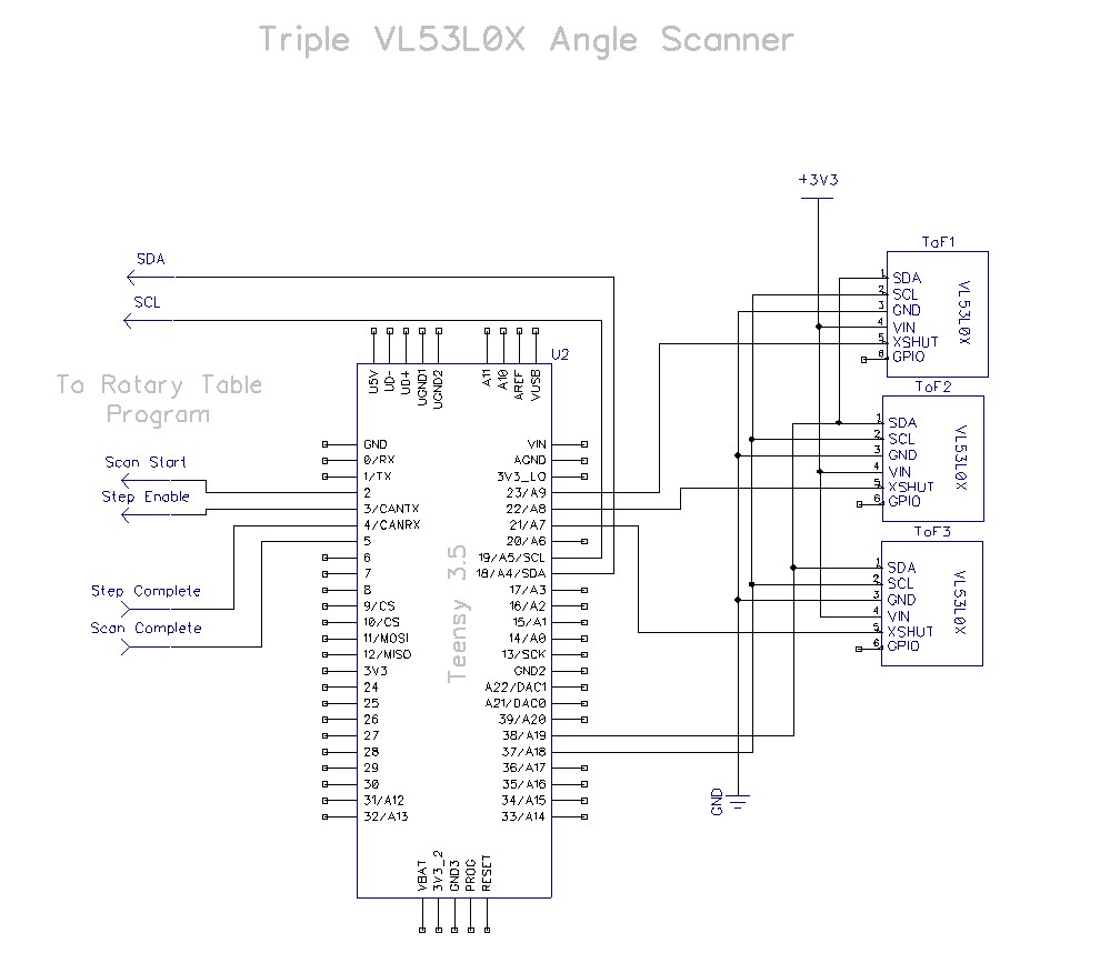
At the conclusion of my last post, I had determined that a three-element linear array of VL53L0X controlled by a Teensy 3.5 was effective in achieving and tracking parallel orientation to a nearby wall. This, should allow the robot to initially orient itself parallel to the target wall and then capture and maintain the desired offset distance.
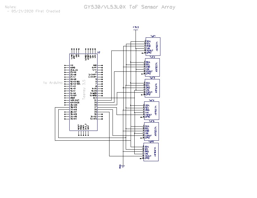
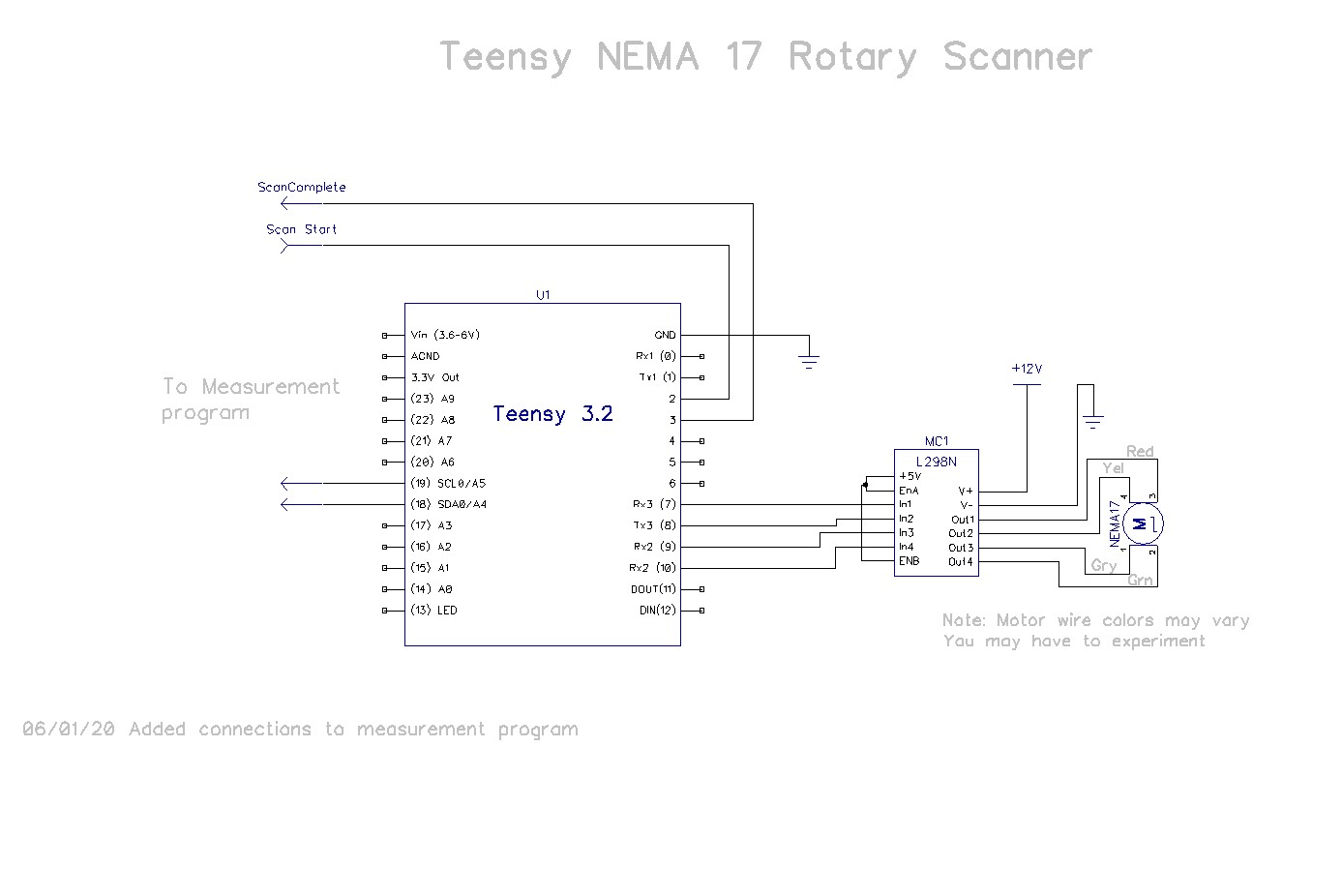
This post describes follow-on efforts to verify that the Arduino Mega 2560 robot controller can acquire distance and steering information from the Teensy 3.5 sensor controller via its I2C bus. Currently the robot system communicates with four devices via I2C – a DF Robots MPU6050 6DOF IMU, an Adafruit DS3231 RTC, an Adafruit FRAM, and the Teensy 3.2 controller for the IR Homing module for autonomous charging. The idea here is to use two three-element linear arrays of VL53L0X modules controlled by a Teensy 3.5 on its secondary I2C bus, controlled by the Mega system controller on the main I2C bus. The Mega would see the Teensy 3.5 as a just a fifth slave device on its I2C bus, and the Teensy 3.5 would handle all the interactions with the VL53L0X sensors. As an added benefit, the Teensy 3.5 can calculate the steering value for tracking, as needed.
The first step in this process was to verify that the Mega could communicate with the Teensy 3.5 over the main I2C bus, while the Teensy 3.5 communicated with the sensor array(s) via its secondary I2C bus. To do this I created two programs – an Arduino Mega program to simulate the main robot controller, and a Teensy 3.5 program to act as the sensor controller (the Teensy program will eventually be the final sensor controller program).
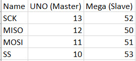
Here’s the Mega 2560 simulator program:
|
1 2 3 4 5 6 7 8 9 10 11 12 13 14 15 16 17 18 19 20 21 22 23 24 25 26 27 28 29 30 31 32 33 34 35 36 37 38 39 40 41 42 43 44 45 46 47 48 49 50 51 52 53 54 55 56 57 58 59 60 61 62 63 64 65 66 67 68 69 70 71 72 73 74 75 76 77 78 79 80 81 82 83 84 85 86 87 88 89 90 91 92 93 94 95 96 97 98 99 100 101 102 103 104 105 106 107 108 109 110 111 112 113 114 115 116 117 118 119 120 121 122 123 124 125 126 127 128 129 130 131 132 133 134 135 136 137 138 139 140 141 142 143 144 |
/* Name: VL53L0X_Master.ino Created: 6/15/2020 1:38:36 PM Author: FRANKNEWXPS15\Frank Program to verify that I can communicate with the Teensy VL53L0X controller via I2C */ #include <PrintEx.h> //allows printf-style printout syntax #include "I2C_Anything.h" //needed for sending float data over I2C StreamEx mySerial = Serial; //added 03/18/18 for printf-style printing const int VL53L0X_SLAVE_ADDRESS = 0x20; //just a guess for now //Sensor data values int Lidar_RightFront; int Lidar_RightCenter; int Lidar_RightRear; int Lidar_LeftFront; int Lidar_LeftCenter; int Lidar_LeftRear; float SteeringVal; enum VL53L0X_REQUEST { VL53L0X_CENTERS_ONLY, VL53L0X_RIGHT, VL53L0X_LEFT }; void setup() { Serial.begin(115200); Wire.begin(); //makes this program the I2C MASTER pinMode(LED_BUILTIN, OUTPUT); mySerial.printf("VL53L0X Master Demo Program\n"); } void loop() { digitalWrite(LED_BUILTIN, HIGH); GetRequestedVL53l0xValues(VL53L0X_RIGHT); //mySerial.printf("VL53L0X F/C/R Values: %d\t%d\t%d\n", Lidar_RightFront, Lidar_RightCenter, Lidar_RightRear); digitalWrite(LED_BUILTIN, LOW); delay(500); } bool GetRequestedVL53l0xValues(VL53L0X_REQUEST which) { //Purpose: Obtain VL53L0X ToF sensor data from Teensy sensor handler //Inputs: // which = VL53L0X_REQUEST value denoting which combination of value to retrieve // VL53L0X_CENTERS_ONLY -> Just the left/right center sensor values // VL53L0X_RIGHT -> All three right sensor values, in front/center/rear order // VL53L0X_LEFT -> All three left sensor values, in front/center/rear order //Outputs: // Requested sensor values, obtained via I2C from the VL53L0X sensor handler // Returns TRUE if data retrieval successful, otherwise FALSE //Plan: // Step1: Send request to VL53L0X handler // Step2: get the requested data //Notes: // Copied from FourWD_WallE2_V4.ino's IsIRBeamAvail() and adapted //Step1: Send request to VL53L0X handler mySerial.printf("Sending %d to slave\n", which); Wire.beginTransmission(VL53L0X_SLAVE_ADDRESS); I2C_writeAnything((uint8_t)which); Wire.endTransmission(); //Step2: get the requested data int readResult = 0; int data_size = 0; switch (which) { case VL53L0X_CENTERS_ONLY: //just two data values needed here data_size = 2 * sizeof(int); Wire.requestFrom(VL53L0X_SLAVE_ADDRESS, (int)(2*sizeof(Lidar_RightCenter))); readResult = I2C_readAnything(Lidar_RightCenter); if (readResult > 0) { I2C_readAnything(Lidar_LeftCenter); } mySerial.printf("VL53L0X_CENTERS_ONLY case: Got LC/RC = %d, %d\n", Lidar_LeftCenter, Lidar_RightCenter); break; case VL53L0X_RIGHT: //four data values needed here data_size = 3 * sizeof(int) + sizeof(float); mySerial.printf("data_size = %d\n", data_size); Wire.requestFrom(VL53L0X_SLAVE_ADDRESS, data_size); readResult = I2C_readAnything(Lidar_RightFront); if (readResult > 0) { readResult = I2C_readAnything(Lidar_RightCenter); } if (readResult > 0) { readResult = I2C_readAnything(Lidar_RightRear); } if (readResult > 0) { readResult = I2C_readAnything(SteeringVal); } mySerial.printf("VL53L0X_RIGHT case: Got L/C/R/S = %d, %d, %d, %3.2f\n", Lidar_RightFront, Lidar_RightCenter, Lidar_RightRear, SteeringVal); break; case VL53L0X_LEFT: //three data values needed here data_size = 3 * sizeof(int) + sizeof(float); Wire.requestFrom(VL53L0X_SLAVE_ADDRESS, data_size); readResult = I2C_readAnything(Lidar_LeftFront); if (readResult > 0) { readResult = I2C_readAnything(Lidar_LeftCenter); } if (readResult > 0) { readResult = I2C_readAnything(Lidar_LeftRear); } if (readResult > 0) { readResult = I2C_readAnything(SteeringVal); } mySerial.printf("VL53L0X_RIGHT case: Got L/C/R/S = %d, %d, %d, %3.2f\n", Lidar_LeftFront, Lidar_LeftCenter, Lidar_LeftRear, SteeringVal); break; default: break; } return readResult > 0; //this is true only if all reads succeed } |
And the Teensy 3.5 program
|
1 2 3 4 5 6 7 8 9 10 11 12 13 14 15 16 17 18 19 20 21 22 23 24 25 26 27 28 29 30 31 32 33 34 35 36 37 38 39 40 41 42 43 44 45 46 47 48 49 50 51 52 53 54 55 56 57 58 59 60 61 62 63 64 65 66 67 68 69 70 71 72 73 74 75 76 77 78 79 80 81 82 83 84 85 86 87 88 89 90 91 92 93 94 95 96 97 98 99 100 101 102 103 104 105 106 107 108 109 110 111 112 113 114 115 116 117 118 119 120 121 122 123 124 125 126 127 128 129 130 131 132 133 134 135 136 137 138 139 140 141 142 143 144 145 146 147 148 149 150 151 152 153 154 155 156 157 158 159 160 161 162 163 164 165 166 167 168 169 170 171 172 173 174 175 176 177 178 179 180 181 182 183 184 185 186 187 188 189 190 191 192 193 194 195 196 197 198 199 200 201 202 203 204 205 206 207 208 209 210 211 212 213 214 215 216 217 218 219 220 221 222 223 224 225 226 227 228 229 230 231 232 233 234 235 236 237 238 239 240 241 242 243 244 245 246 247 248 249 250 251 252 253 254 255 |
/* Name: Teensy_VL53L0X_I2C_Slave.ino Created: 6/15/2020 11:45:03 AM Author: FRANKNEWXPS15\Frank This program builds on Teensy_Triple_VL53L0X_V2.ino and adds an I2C SLAVE connection for transmitting sensor readings to a master controller (a Mega 2560 in the case of the 4-wheel robot) */ #include <Wire.h> //using Wire.h here instead of i2c_t3.h for multiple I2C bus access #include "Adafruit_VL53L0X.h" #include "I2C_Anything.h" //local version modified to use Wire.h vs SBWire volatile uint8_t request_type; Adafruit_VL53L0X lidar_RF = Adafruit_VL53L0X(); //Right-front LIDAR (angled 30 deg forward) Adafruit_VL53L0X lidar_RC = Adafruit_VL53L0X(); //Center LIDAR Adafruit_VL53L0X lidar_RR = Adafruit_VL53L0X(); //Right-rear LIDAR (angled 30 deg rearward) //XSHUT required for I2C address init const int RF_XSHUT_PIN = 23; const int RC_XSHUT_PIN = 22; const int RR_XSHUT_PIN = 21; const int MAX_LIDAR_RANGE_MM = 1000; //make it obvious when nearest object is out of range uint16_t RF_Dist_mm; uint16_t RC_Dist_mm; uint16_t RR_Dist_mm; float SteeringVal; const int SLAVE_ADDRESS = 0x20; //just a guess for now void setup() { Wire.begin(SLAVE_ADDRESS); //set Teensy Wire0 port up as slave Wire.onRequest(requestEvent); //ISR for I2C requests from master (Mega 2560) Wire.onReceive(receiveEvent); //ISR for I2C data from master (Mega 2560) Serial.begin(115200); //Teensy ignores rate parameter pinMode(RF_XSHUT_PIN, OUTPUT); pinMode(RC_XSHUT_PIN, OUTPUT); pinMode(RR_XSHUT_PIN, OUTPUT); // wait until serial port opens for native USB devices while (!Serial) { delay(1); } delay(5000); //05/28/20 - this delay is necessary AFTER Serial instantiation! Serial.printf("Teensy 3.5 VL53L0X Sensor Array Controller\n"); //initialize 3 LIDAR sensors // 1. Reset all sensors by setting all of their XSHUT pins low for delay(10), then set // all XSHUT high to bring out of reset digitalWrite(RF_XSHUT_PIN, LOW); delay(10); digitalWrite(RC_XSHUT_PIN, LOW); delay(10); digitalWrite(RR_XSHUT_PIN, LOW); delay(10); digitalWrite(RF_XSHUT_PIN, HIGH); digitalWrite(RC_XSHUT_PIN, HIGH); digitalWrite(RR_XSHUT_PIN, HIGH); // 2. Keep sensor #1 awake by keeping XSHUT pin high, and put all other sensors into // shutdown by pulling XSHUT pins low digitalWrite(RC_XSHUT_PIN, LOW); digitalWrite(RR_XSHUT_PIN, LOW); // 4. Initialize sensor #1 if (!lidar_RF.begin(VL53L0X_I2C_ADDR + 1, false, &Wire1)) { Serial.println(F("Failed to boot lidar_RF")); while (1); } // 5. Keep sensor #1 awake, and now bring sensor #2 out of reset by setting its XSHUT pin high. // 6. Initialize sensor #2 with lox.begin(new_i2c_address) Pick any number but 0x29 and whatever // you set the first sensor to digitalWrite(RC_XSHUT_PIN, HIGH); if (!lidar_RC.begin(VL53L0X_I2C_ADDR + 2, false, &Wire1)) { Serial.println(F("Failed to boot lidar_RC")); while (1); } // 7. Repeat for each sensor, turning each one on, setting a unique address. digitalWrite(RR_XSHUT_PIN, HIGH); if (!lidar_RR.begin(VL53L0X_I2C_ADDR + 3, false, &Wire1)) { Serial.println(F("Failed to boot lidar_RR")); while (1); } Serial.printf("\nInit complete\n\n"); ////05/23/20 experiment with accessing API functions //VL53L0X_Dev_t RightFrontDevice = lidar_RF.GetDeviceHandle(); //VL53L0X_DeviceInfo_t RightFrontDeviceInfo = lidar_RF.GetDeviceInfo(); //Serial.printf("Device Info for Right Front Sensor\n"); //Serial.printf("\tName = %s\n\tType = %s\n\tProdID = %s\n\tType Number = %d\n\tMajor Rev = %d\n\tMinor Rev = %d\n \n", // RightFrontDeviceInfo.Name, RightFrontDeviceInfo.Type, // RightFrontDeviceInfo.ProductId, RightFrontDeviceInfo.ProductType, // RightFrontDeviceInfo.ProductRevisionMajor, RightFrontDeviceInfo.ProductRevisionMinor); ////get measurement timing budget? //prog_uint32_t MeasBudgetUSec; ////VL53L0X_Error ApiError = VL53L0X_GetMeasurementTimingBudgetMicroSeconds(&RightFrontDevice, &MeasBudgetUSec); //VL53L0X_GetMeasurementTimingBudgetMicroSeconds(&RightFrontDevice, &MeasBudgetUSec); //Serial.printf("Right Front Measurement Budget (uSec) = %d\n", MeasBudgetUSec); //delay(1000); //Serial.printf("Changing budget from %d to %d....\n", MeasBudgetUSec, 2 * MeasBudgetUSec); //delay(1000); //MeasBudgetUSec = 2 * MeasBudgetUSec; ////ApiError = VL53L0X_SetMeasurementTimingBudgetMicroSeconds(&RightFrontDevice, MeasBudgetUSec); //VL53L0X_SetMeasurementTimingBudgetMicroSeconds(&RightFrontDevice, MeasBudgetUSec); //Serial.printf("Right Front Measurement Budget (uSec) Now = %d\n \n", MeasBudgetUSec); //Serial.printf("Msec\tFront\tCenter\tRear\tSteer\n"); } void loop() { VL53L0X_RangingMeasurementData_t measure; lidar_RF.rangingTest(&measure, false); // pass in 'true' to get debug data printout! if (measure.RangeStatus != 4) // phase failures have incorrect data { RF_Dist_mm = measure.RangeMilliMeter; if (RF_Dist_mm > MAX_LIDAR_RANGE_MM) RF_Dist_mm = MAX_LIDAR_RANGE_MM; } else RF_Dist_mm = 0; //delay(100); lidar_RC.rangingTest(&measure, false); // pass in 'true' to get debug data printout! if (measure.RangeStatus != 4) // phase failures have incorrect data { RC_Dist_mm = measure.RangeMilliMeter; if (RC_Dist_mm > MAX_LIDAR_RANGE_MM) RC_Dist_mm = MAX_LIDAR_RANGE_MM; } else RC_Dist_mm = 0; //delay(100); lidar_RR.rangingTest(&measure, false); // pass in 'true' to get debug data printout! if (measure.RangeStatus != 4) // phase failures have incorrect data { RR_Dist_mm = measure.RangeMilliMeter; if (RR_Dist_mm > MAX_LIDAR_RANGE_MM) RR_Dist_mm = MAX_LIDAR_RANGE_MM; } else RR_Dist_mm = 0; SteeringVal = (RF_Dist_mm - RR_Dist_mm) / (float)RC_Dist_mm; //DEBUG!! //Serial.printf("%lu\t%d\t%d\t%d\t%3.2f\n", millis(), // RF_Dist_mm, RC_Dist_mm, RR_Dist_mm, SteeringVal); //DEBUG!! delay(100); } // function that executes whenever data is requested by master // this function is registered as an event, see setup() void requestEvent() { //Purpose: Send requested sensor data to the Mega controller via main I2C bus //Inputs: // request_type = uint8_t value denoting type of data requested // 0 = left & right center distances only // 1 = right side front, center and rear distances, plus steering value // 2 = left side front, center and rear distances, plus steering value //Outputs: // Requested data sent to master //DEBUG!! Serial.printf("RequestEvent() with request_type = %d: VL53L0X Front/Center/Rear distances = %d, %d, %d\n", request_type, RF_Dist_mm, RC_Dist_mm, RR_Dist_mm); //DEBUG!! int data_size; switch (request_type) { case 0: //VL53L0X_CENTERS_ONLY //DEBUG!! data_size = sizeof(uint16_t); Serial.printf("Sending %d bytes RC_Dist_mm = %d to master\n", data_size, RC_Dist_mm); //DEBUG!! I2C_writeAnything(RC_Dist_mm); break; case 1: //VL53L0X_RIGHT //DEBUG!! data_size = 3 * sizeof(uint16_t) + sizeof(float); Serial.printf("Sending %d bytes F/C/R/S vals = %d, %d, %d, %3.2f to master\n", data_size, RF_Dist_mm, RC_Dist_mm, RR_Dist_mm, SteeringVal); //DEBUG!! I2C_writeAnything(RF_Dist_mm); I2C_writeAnything(RC_Dist_mm); I2C_writeAnything(RR_Dist_mm); I2C_writeAnything(SteeringVal); break; case 2: //VL53L0X_LEFT //DEBUG!! //data_size = 3 * sizeof(uint16_t) + sizeof(float); //Serial.printf("Sending %d bytes F/C/R/S vals = %d, %d, %d, %3.2f to master\n", // data_size, RF_Dist_mm, RC_Dist_mm, RR_Dist_mm, SteeringVal); //DEBUG!! //I2C_writeAnything(LF_Dist_mm); //I2C_writeAnything(LC_Dist_mm); //I2C_writeAnything(LR_Dist_mm); //I2C_writeAnything(SteeringVal); break; default: break; } } // // handle Rx Event (incoming I2C data) // void receiveEvent(int numBytes) { //Purpose: capture data request type from Mega I2C master //Inputs: // numBytes = int value denoting number of bytes received from master //Outputs: // uint8_t request_type filled with request type value from master //DEBUG!! Serial.printf("receiveEvent(%d)\n", numBytes); //DEBUG!! I2C_readAnything(request_type); //DEBUG!! Serial.printf("receiveEvent: Got %d from master\n", request_type); //DEBUG!! } |
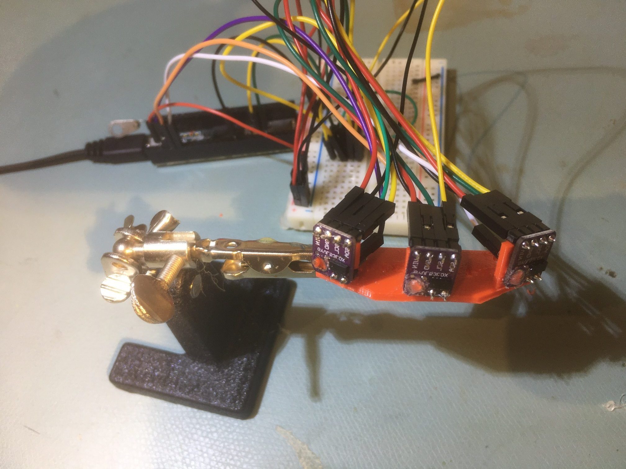
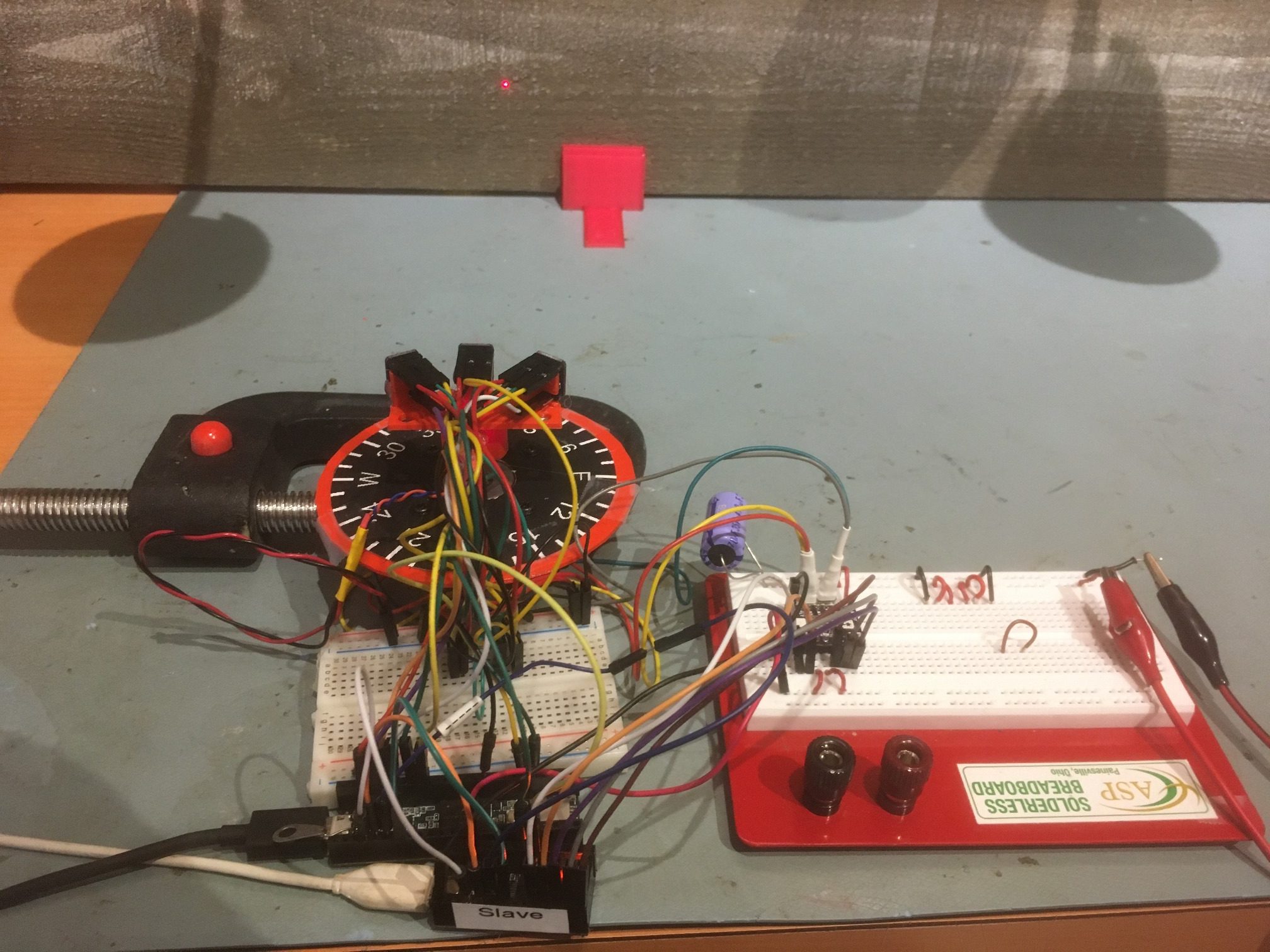
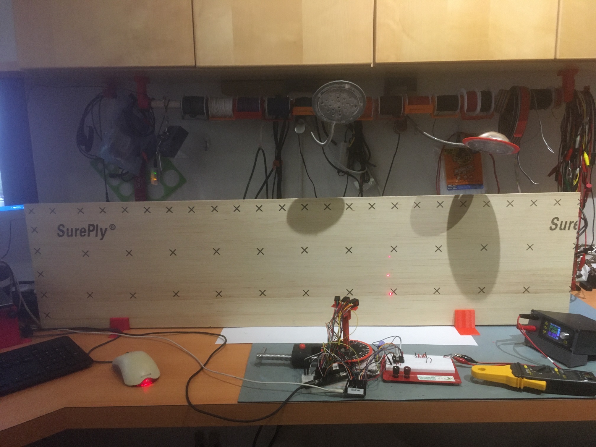
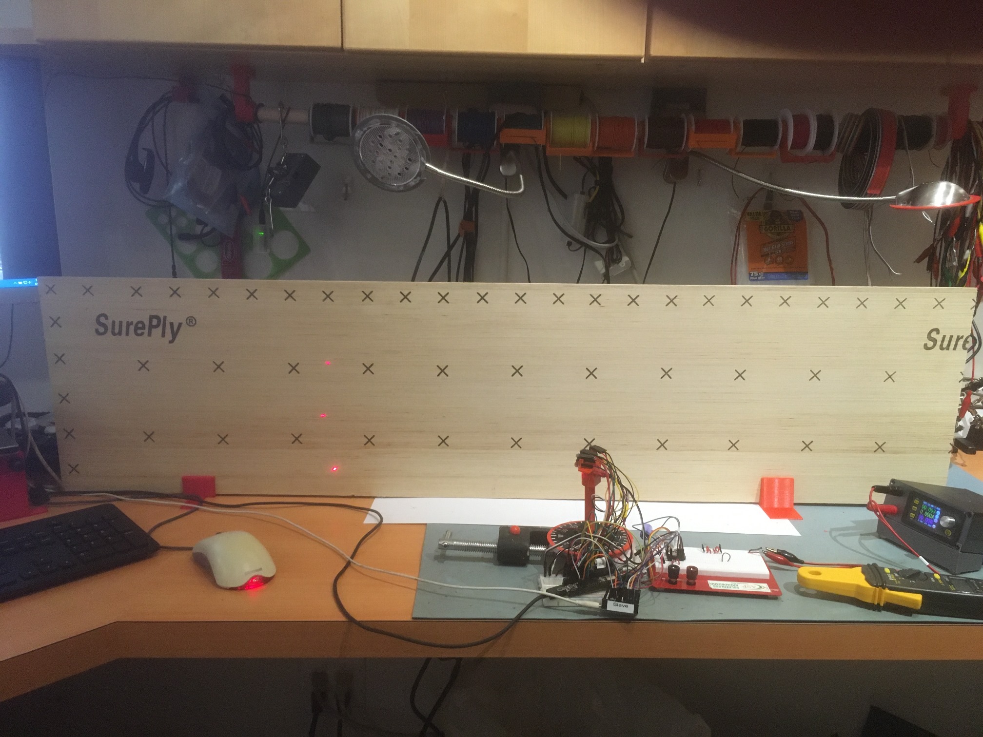
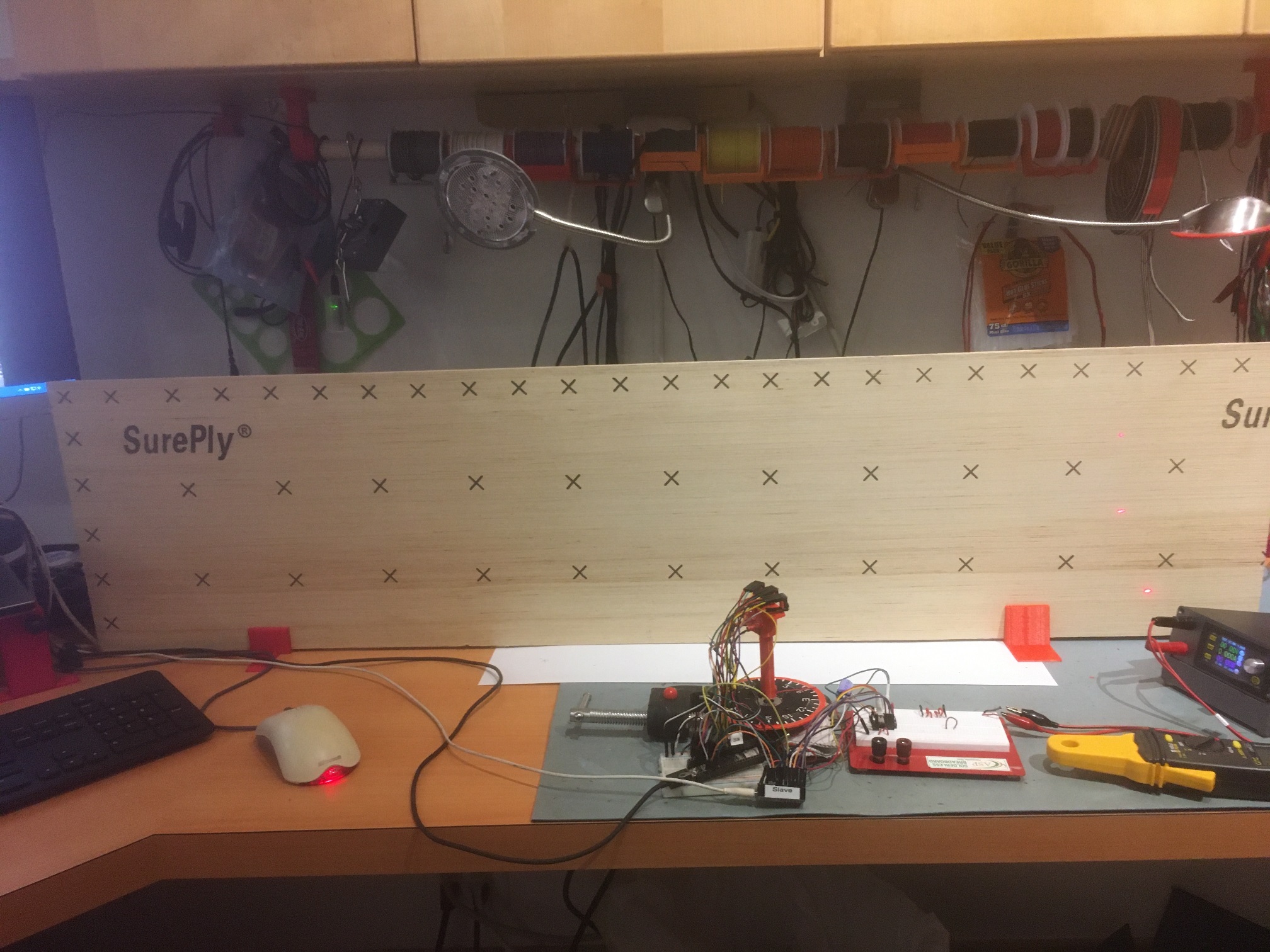
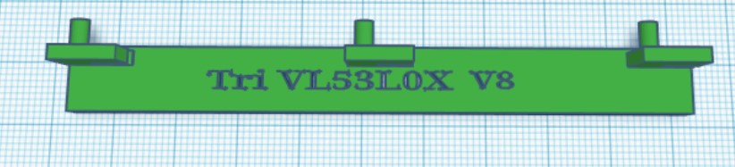
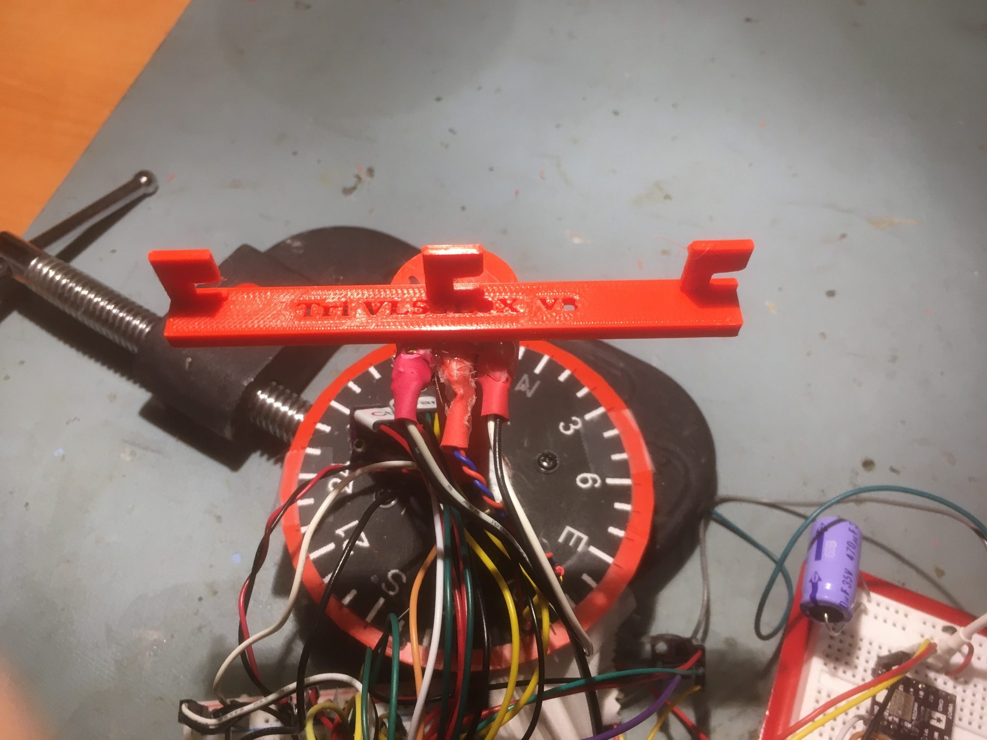
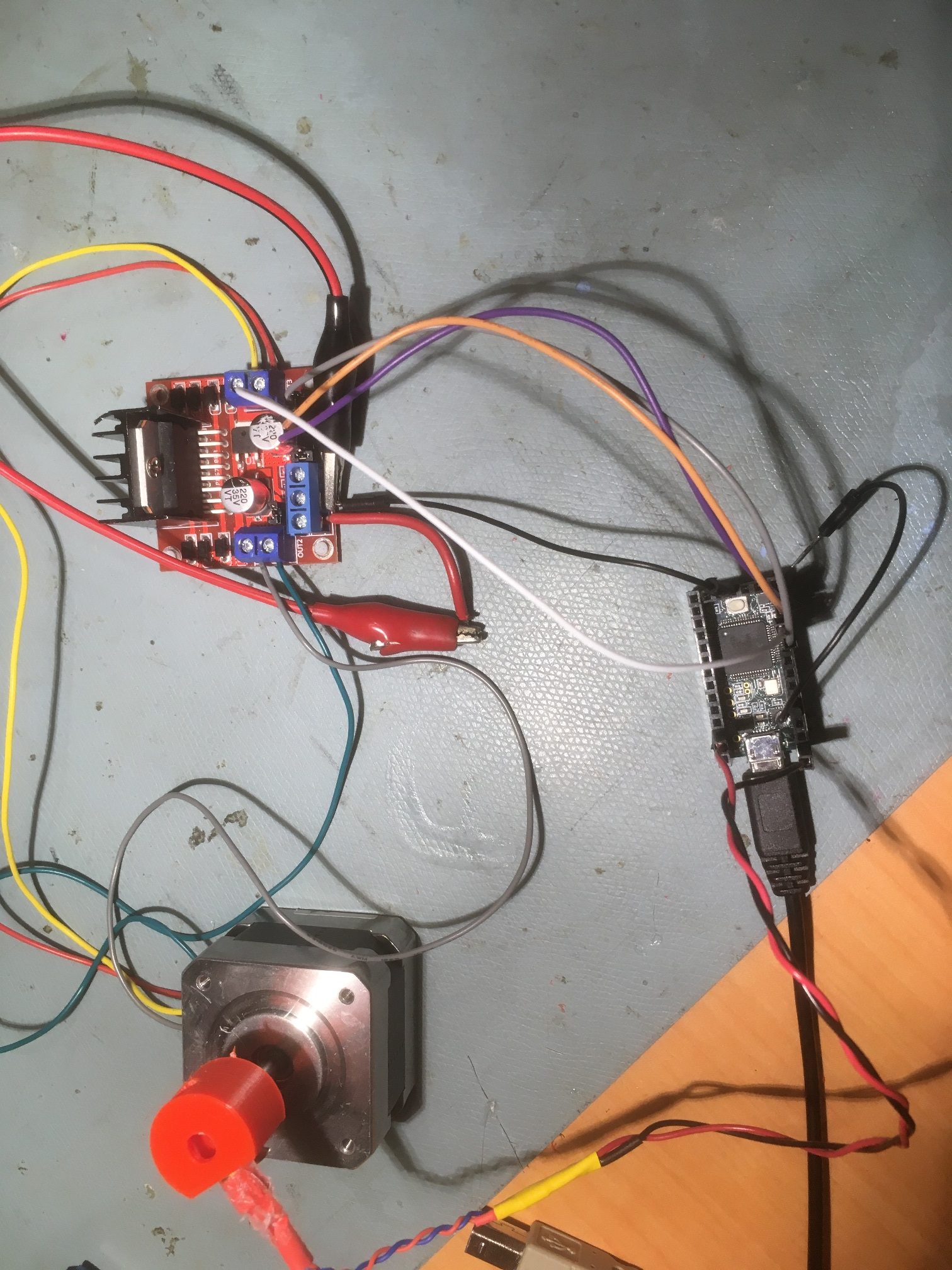
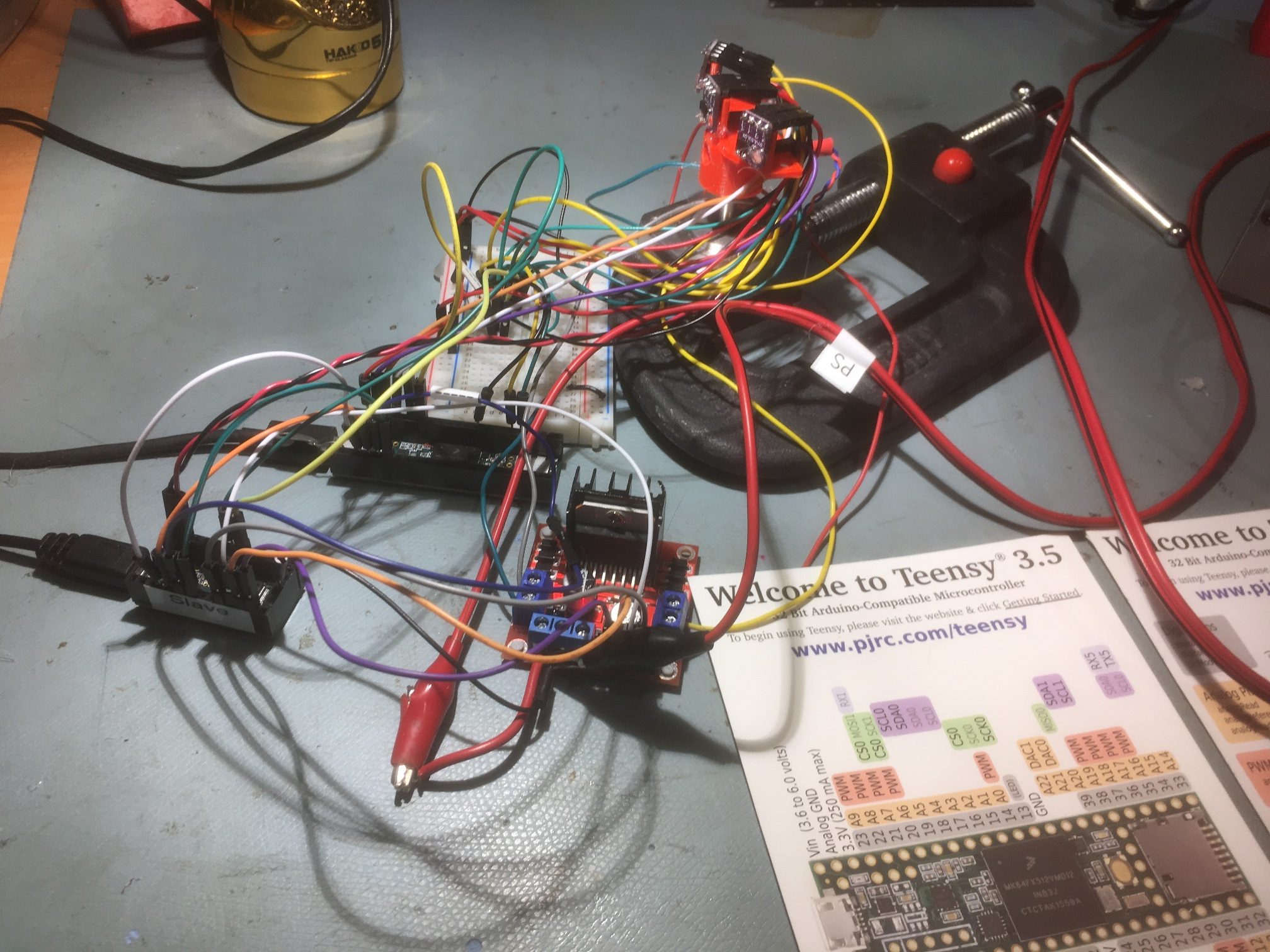
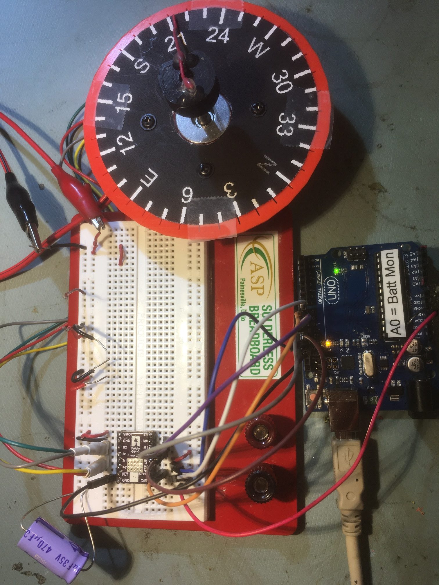
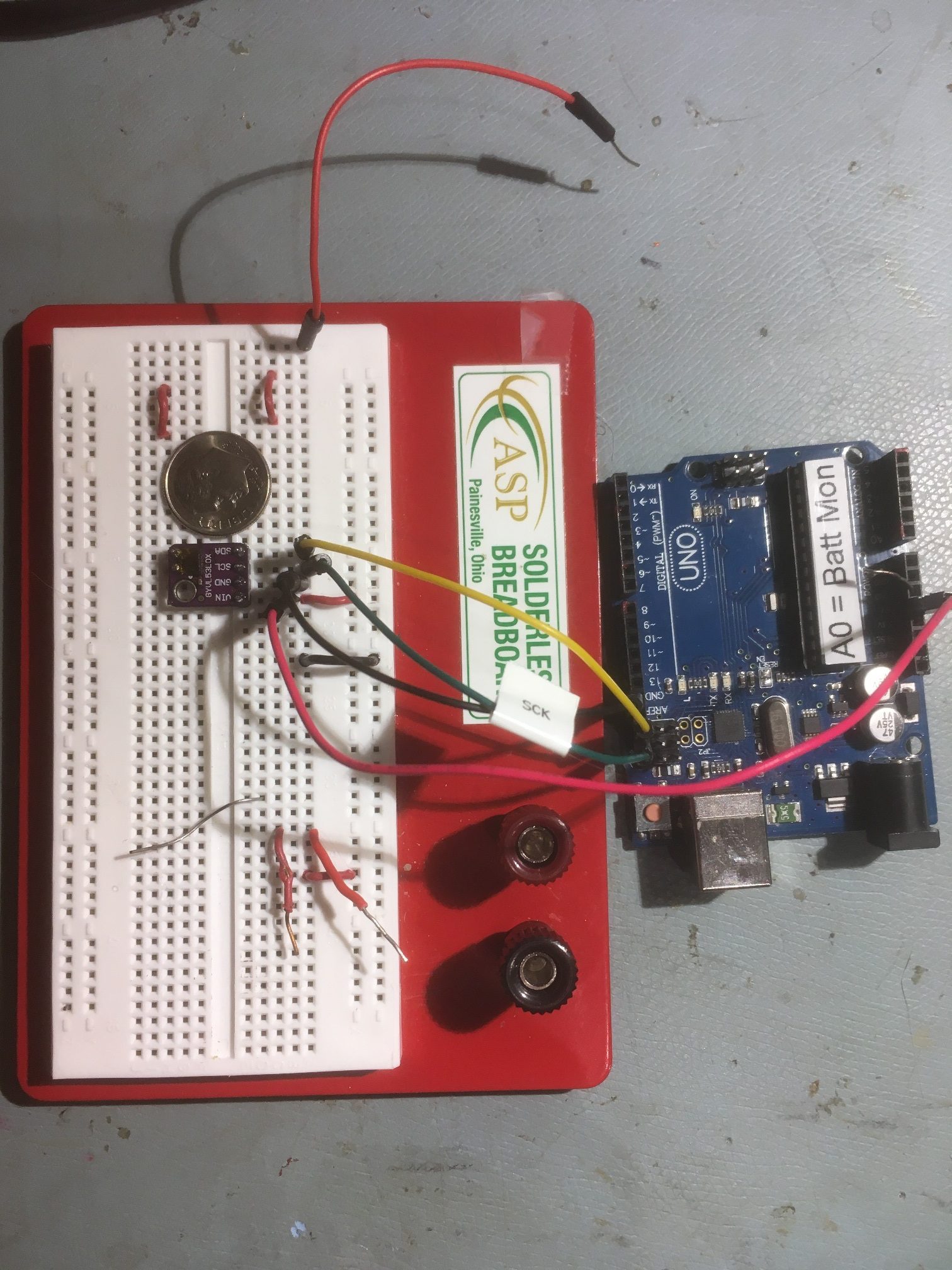
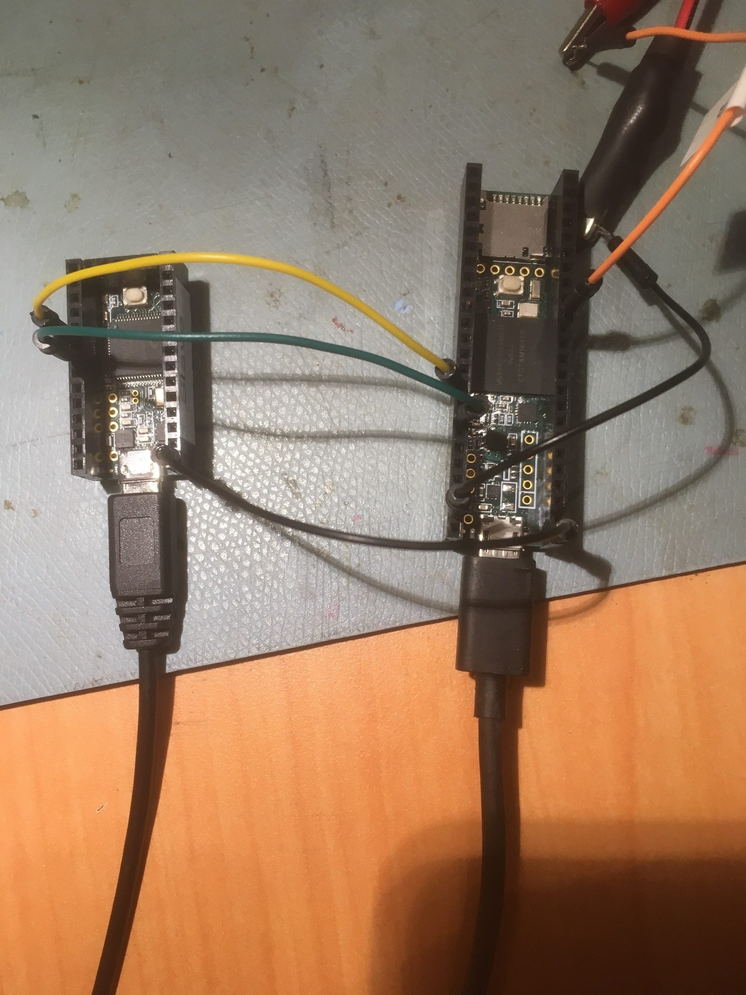
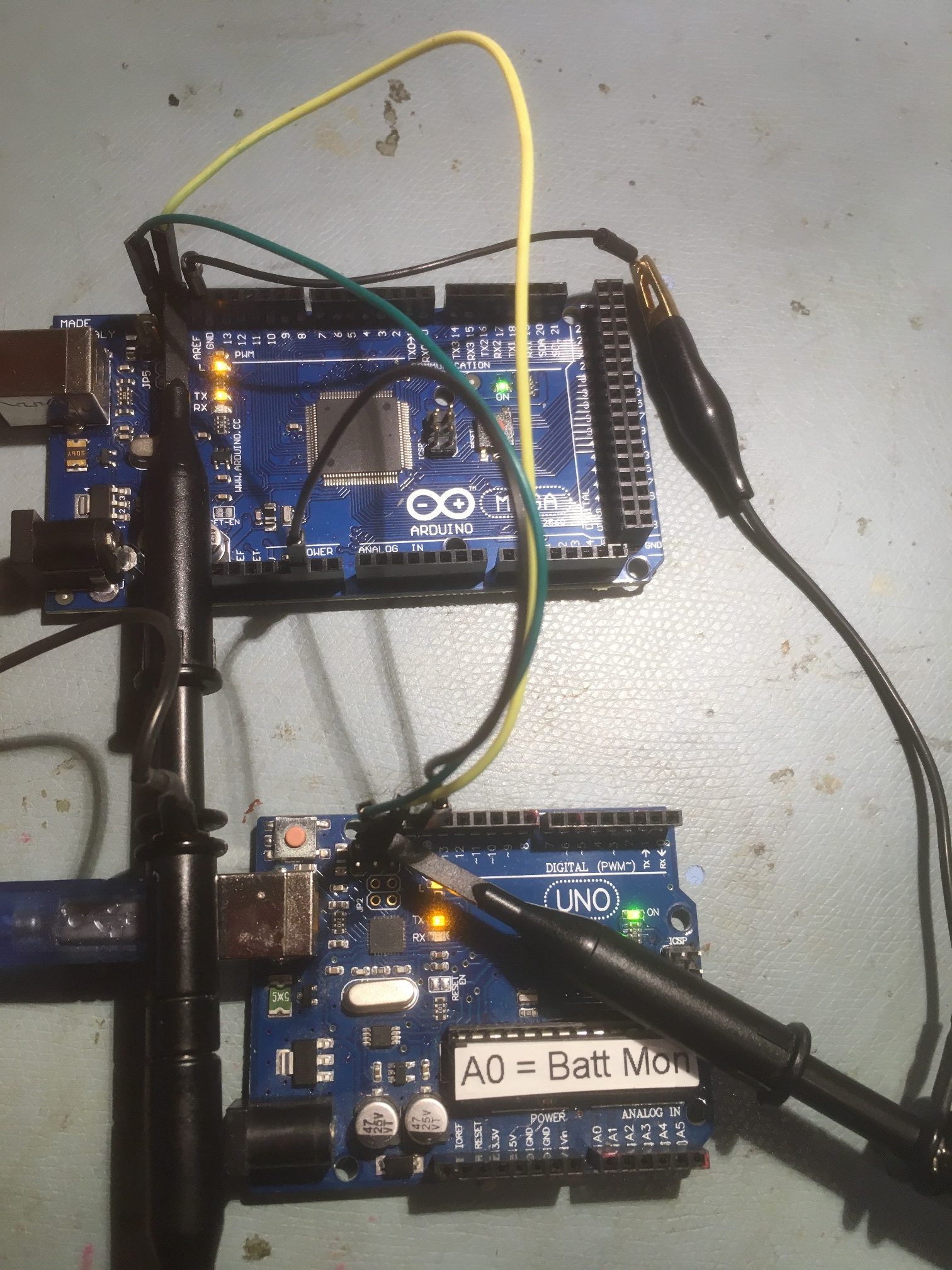
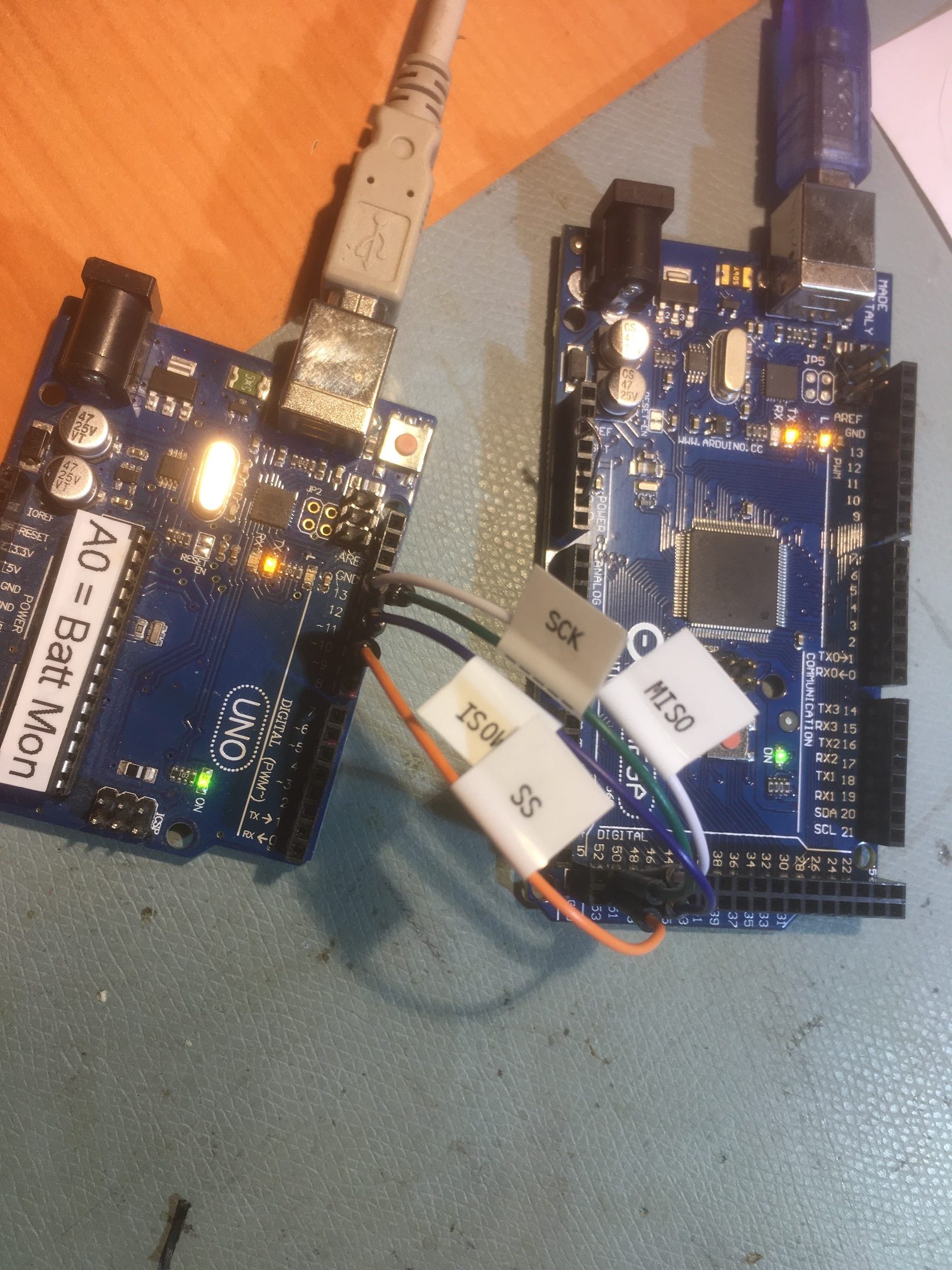
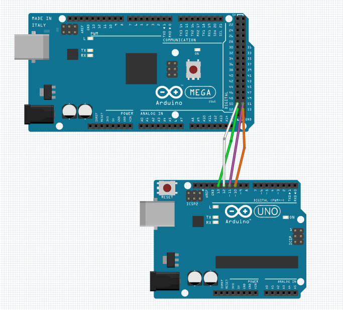
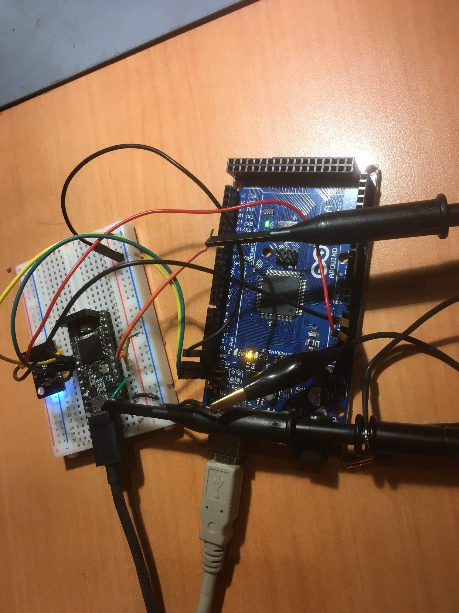
Here’s the hardware layout for the first test:
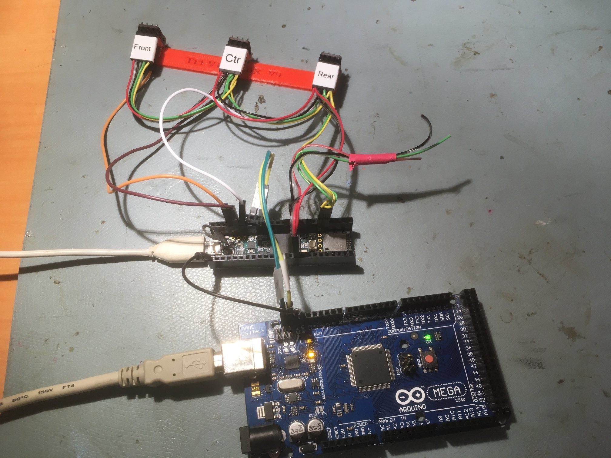
Arduino Mega system controller in the foreground, followed by the Teensy 3.5 sensor array controller in the middle, followed by a single 3-element sensor array in the background
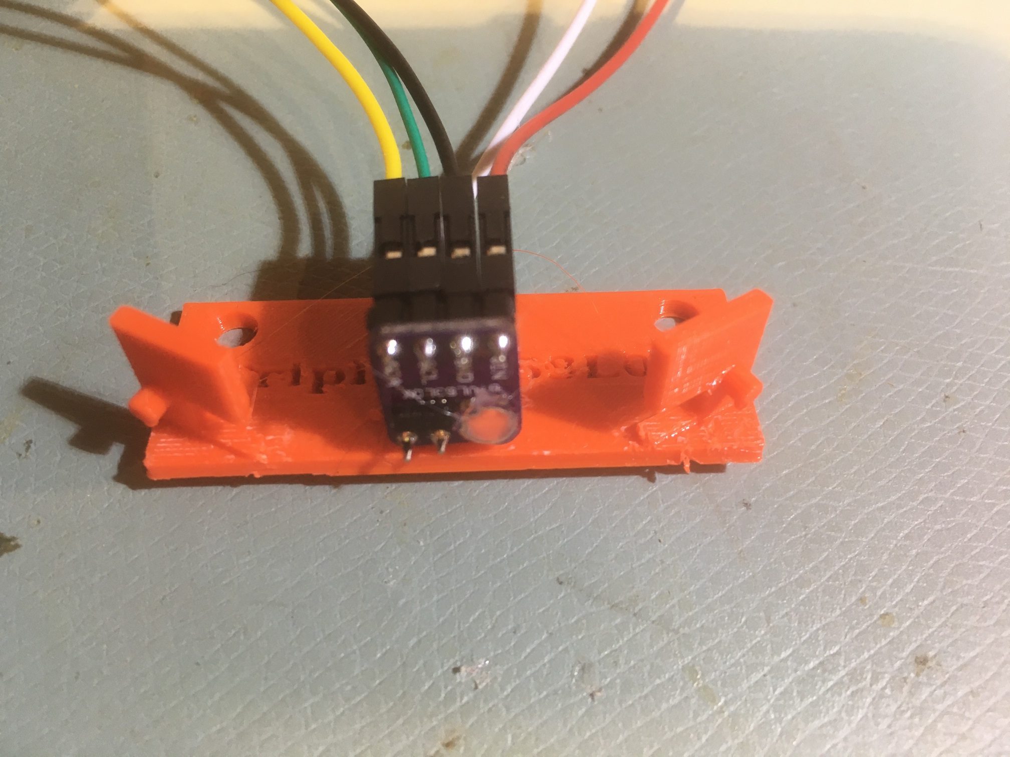
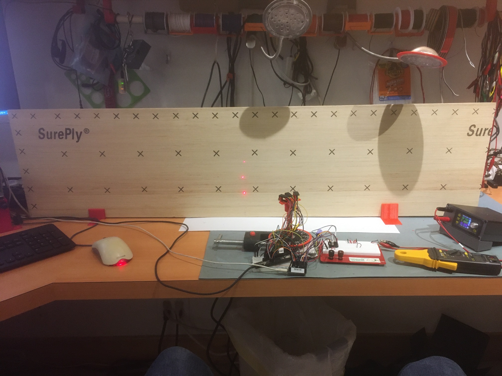
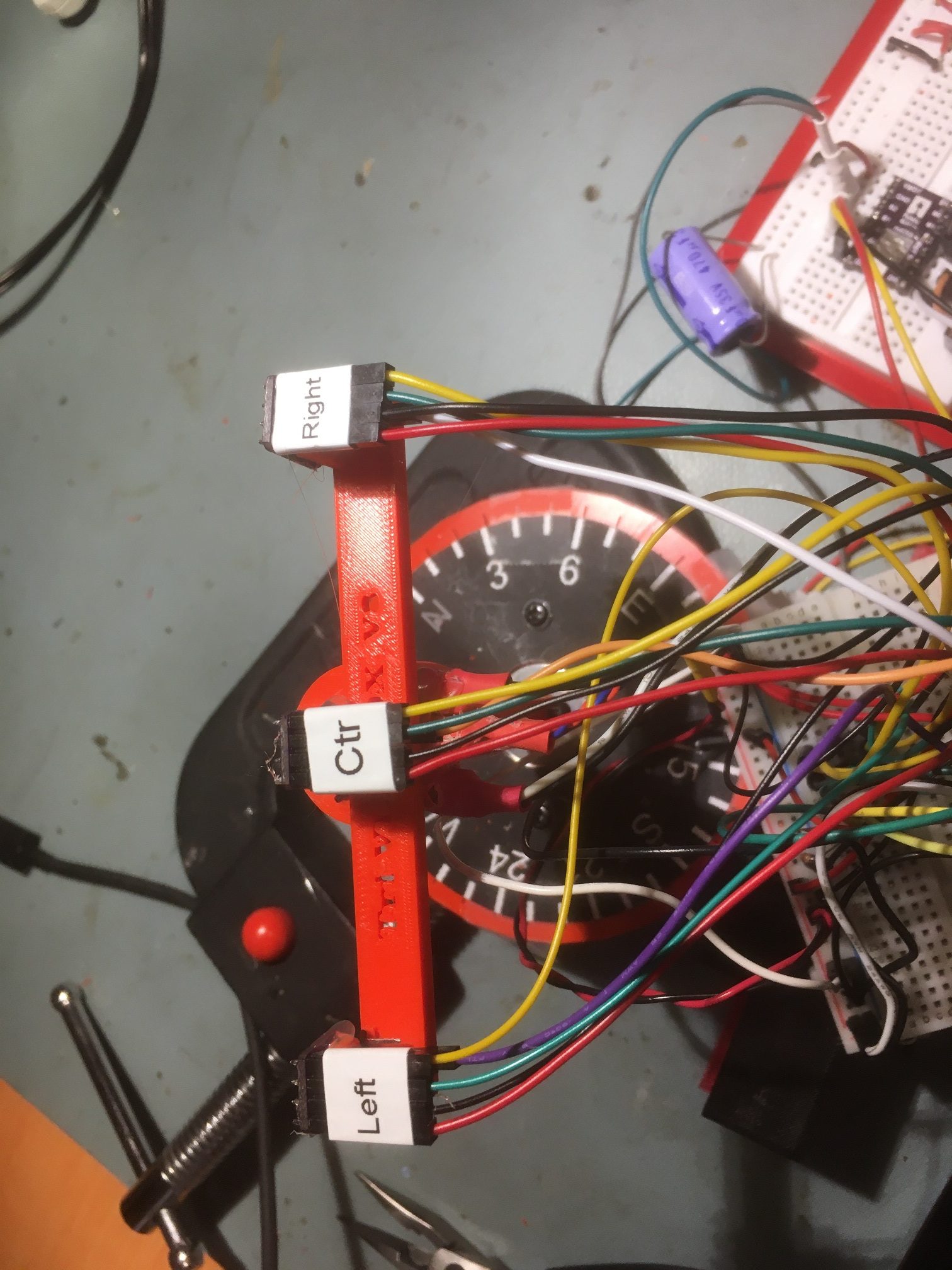
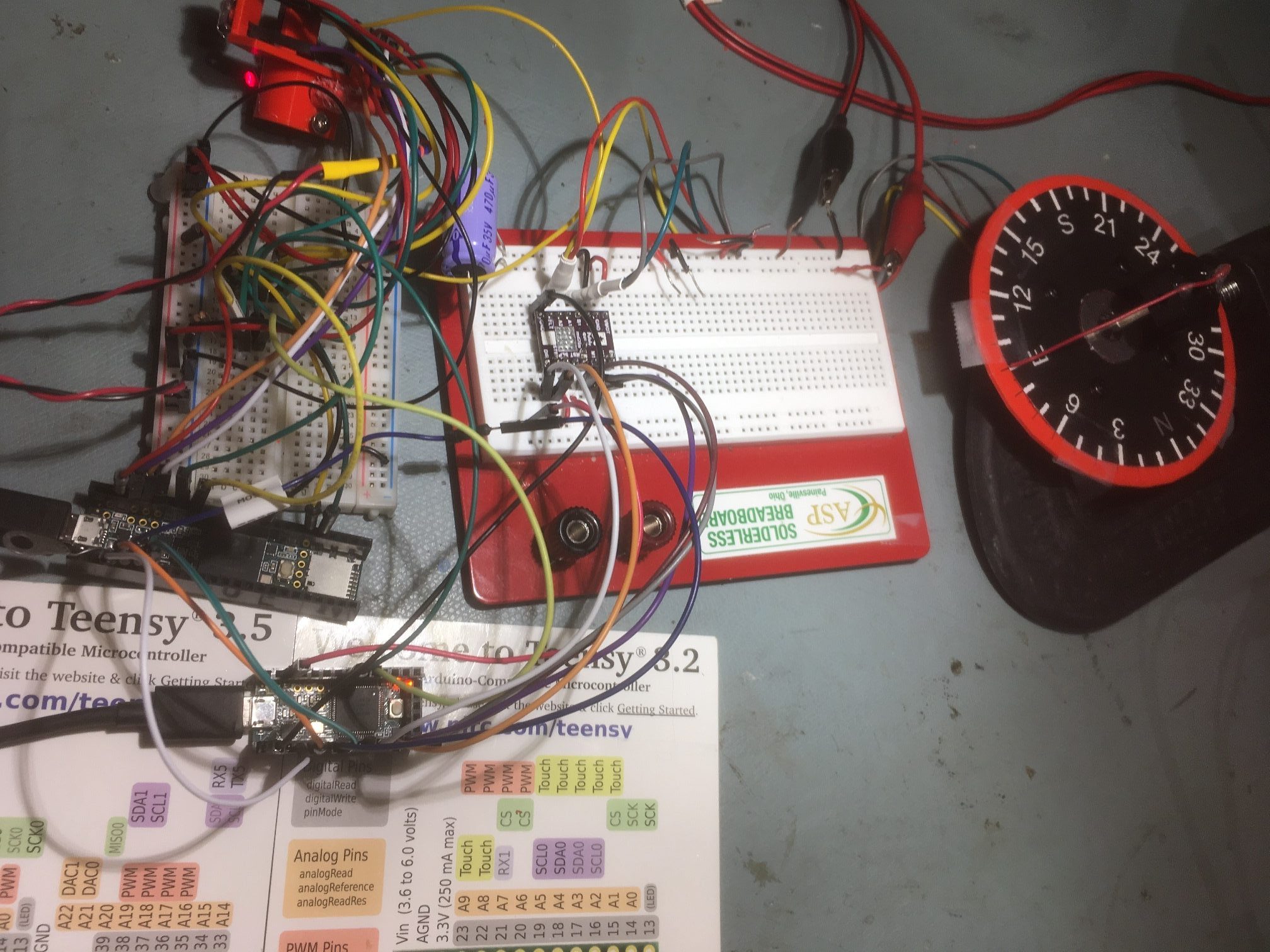
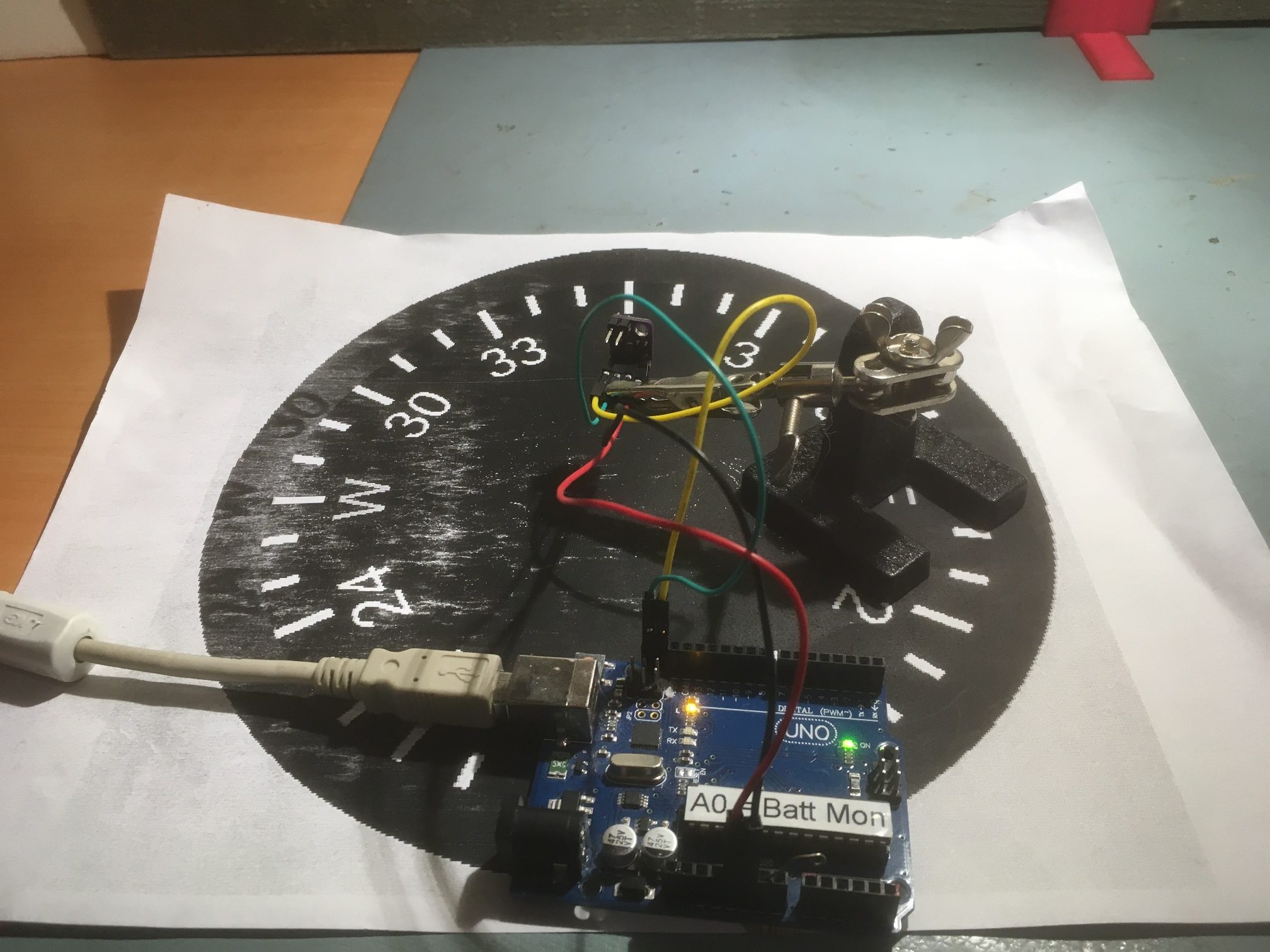
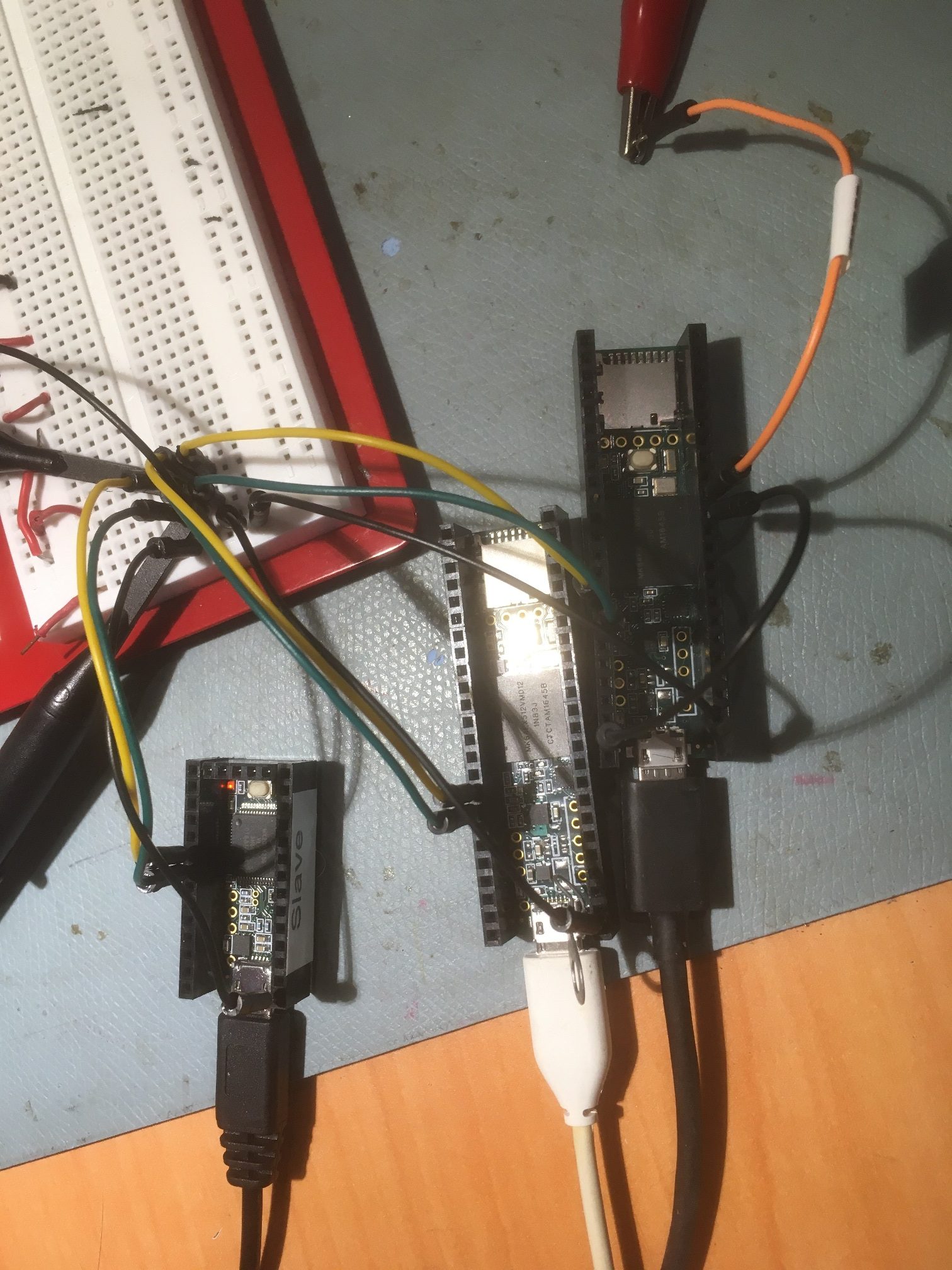
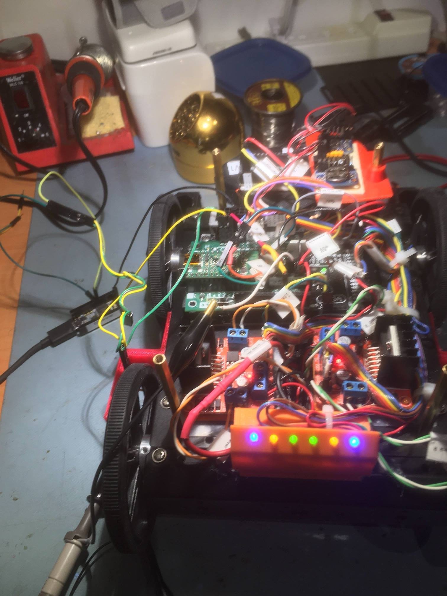
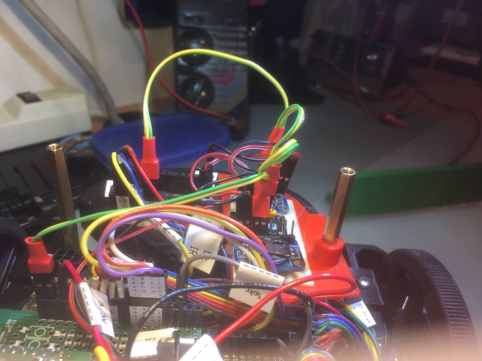
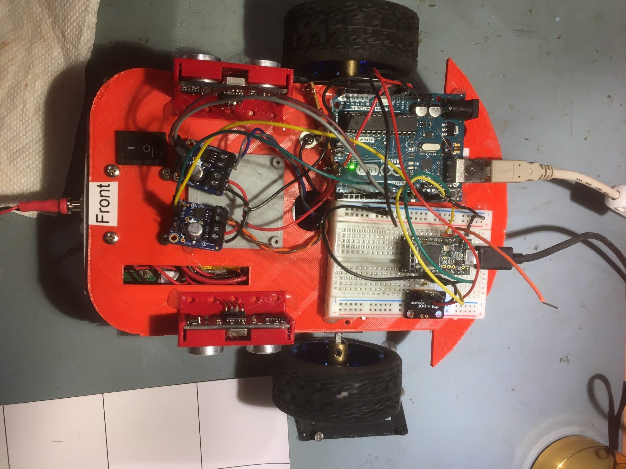
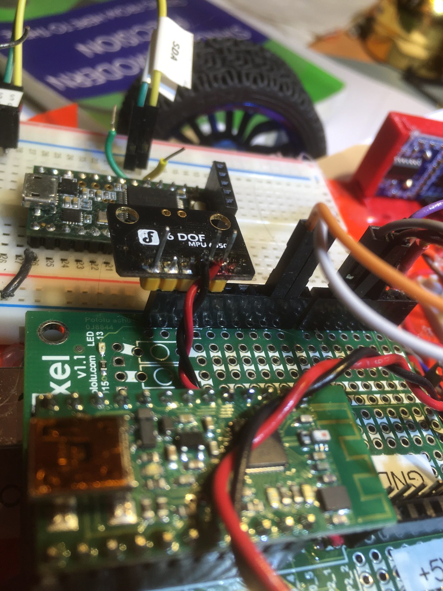
The next step was to mount everything on the robot’s second deck, and verify that the Teensy 3.5 sensor array controller can talk to the robot’s Mega controller via the robot’s I2C bus. Here’s the hardware layout:
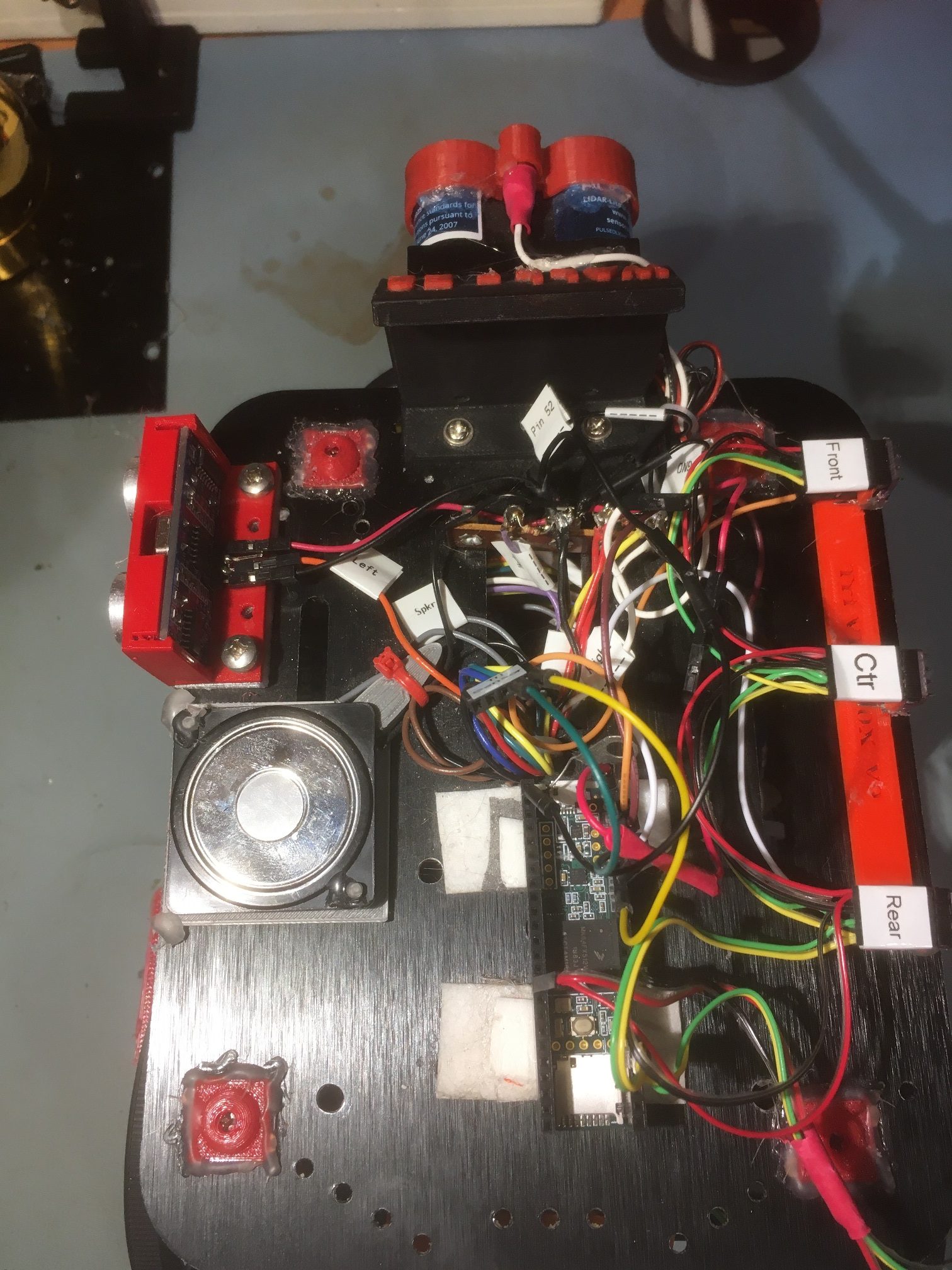
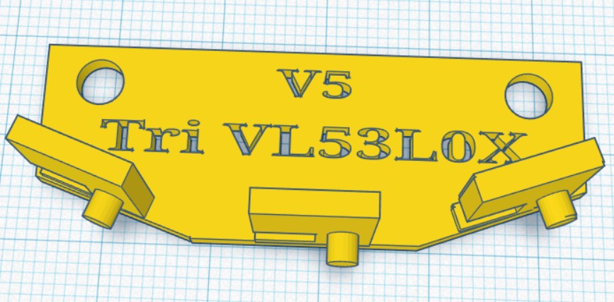
Right-side three sensor array mounted on robot second deck. Teensy 3.5 sensor array controller shown at middle foreground.
After mounting the array and array controller on the robot’s second deck, I connected the Teensy to robot +5V, GND and the I2C bus, and loaded the VL53L0X_Master.ino sketch into the robot’s Mega system controller. With this setup I was able to demonstrate much improved parallel orientation detection. The setup is much more precise and straightforward than the previous algorithm using the ‘ping’ sensors. Instead of having to make several turns toward and away from the near wall looking for a distance inflection point, I can now determine immediately from the sign of the steering value which way to turn, and can detect the parallel condition when the steering value changes sign.
I think I may even be able to use this new ‘super-power’ to simplify the initial ‘offset capture’ phase, as well as the offset tracking phase. In earlier work I demonstrated that I can use a PID engine to drive a stepper motor to keep the sensor array parallel to a moving target ‘wall’, so I’m confident I can use the same technique to drive the robot’s motors to maintain a parallel condition with respect to a nearby wall, by driving the steering value toward zero. In addition, I should be able to set the PID ‘setpoint’ to a non-zero value and cause the robot to assume a stable oblique orientation with respect to the wall, meaning I should be able to have the robot drive at a stable oblique angle toward or away from the wall to capture the desired offset.
19 June 2020 Update:
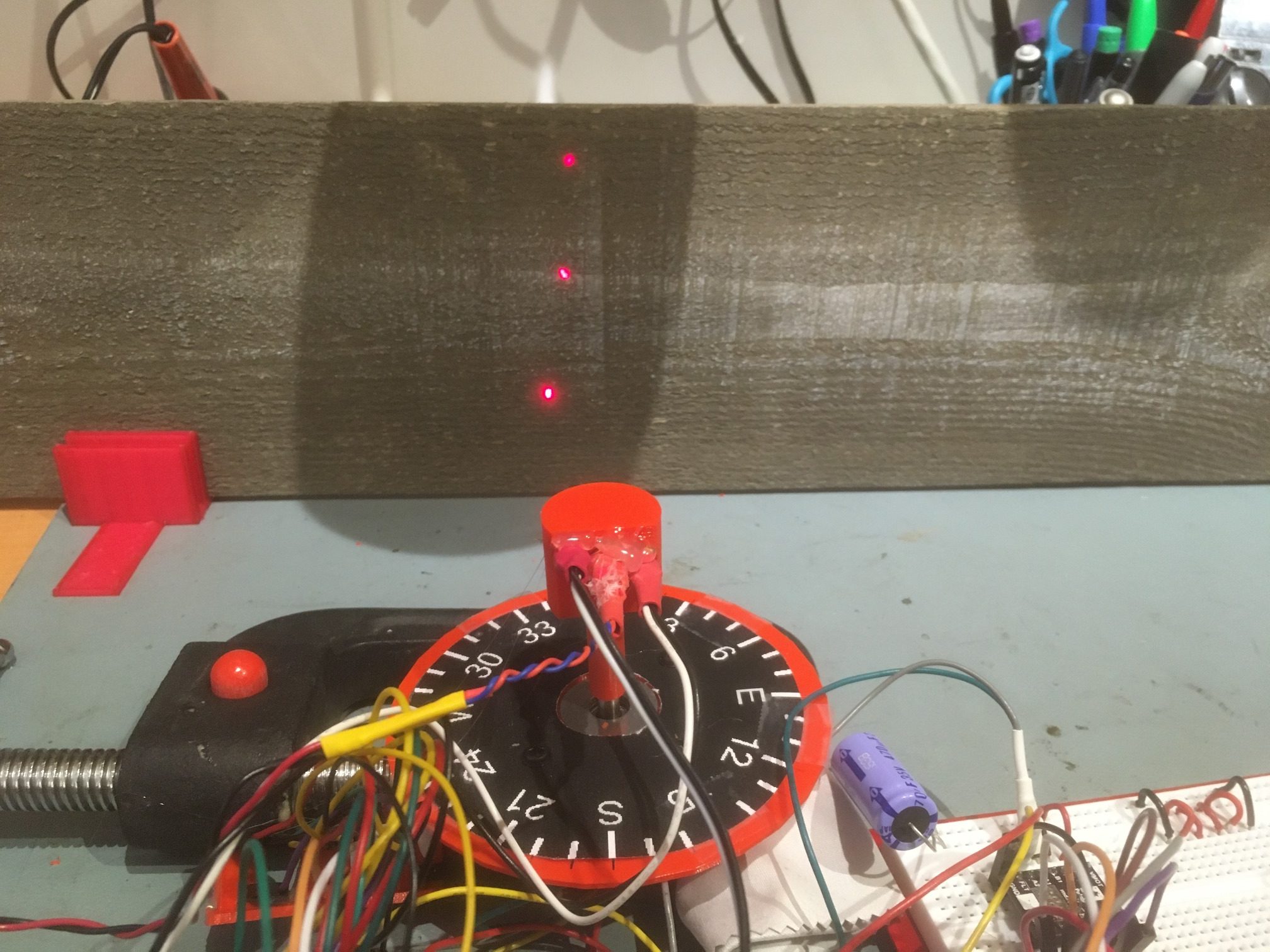
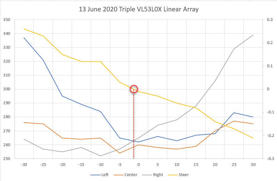
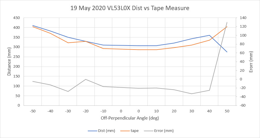
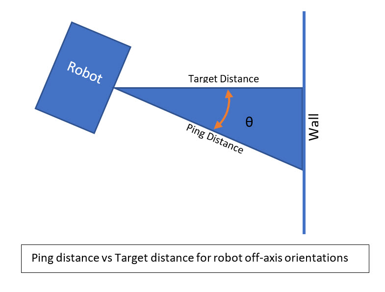
As a preliminary step to using a PID engine to drive the ‘RotateToParallelOrientation’ maneuver, I modified the robot code to report the front, center, and rear distances from the VL53L0X array, along with the calculated steering value computed as (F-R)/C. Then I recorded the distance and steering value vs relative pointing angle for 20, 30, and 40 cm offsets from my target ‘wall’.
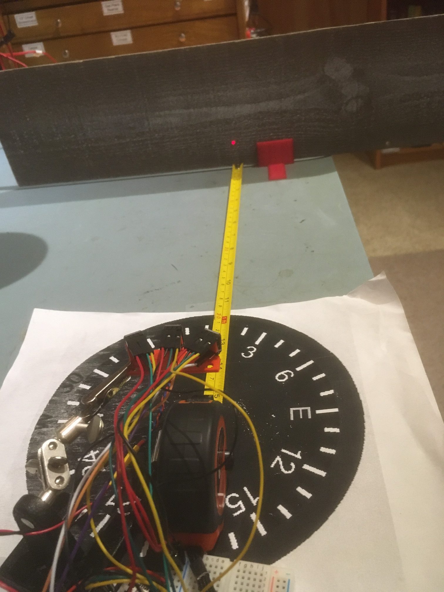
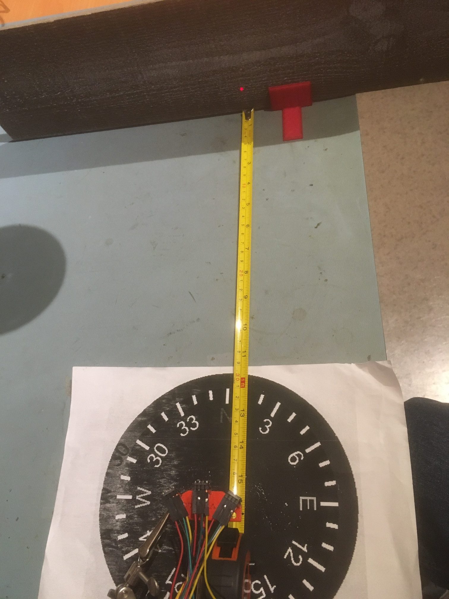
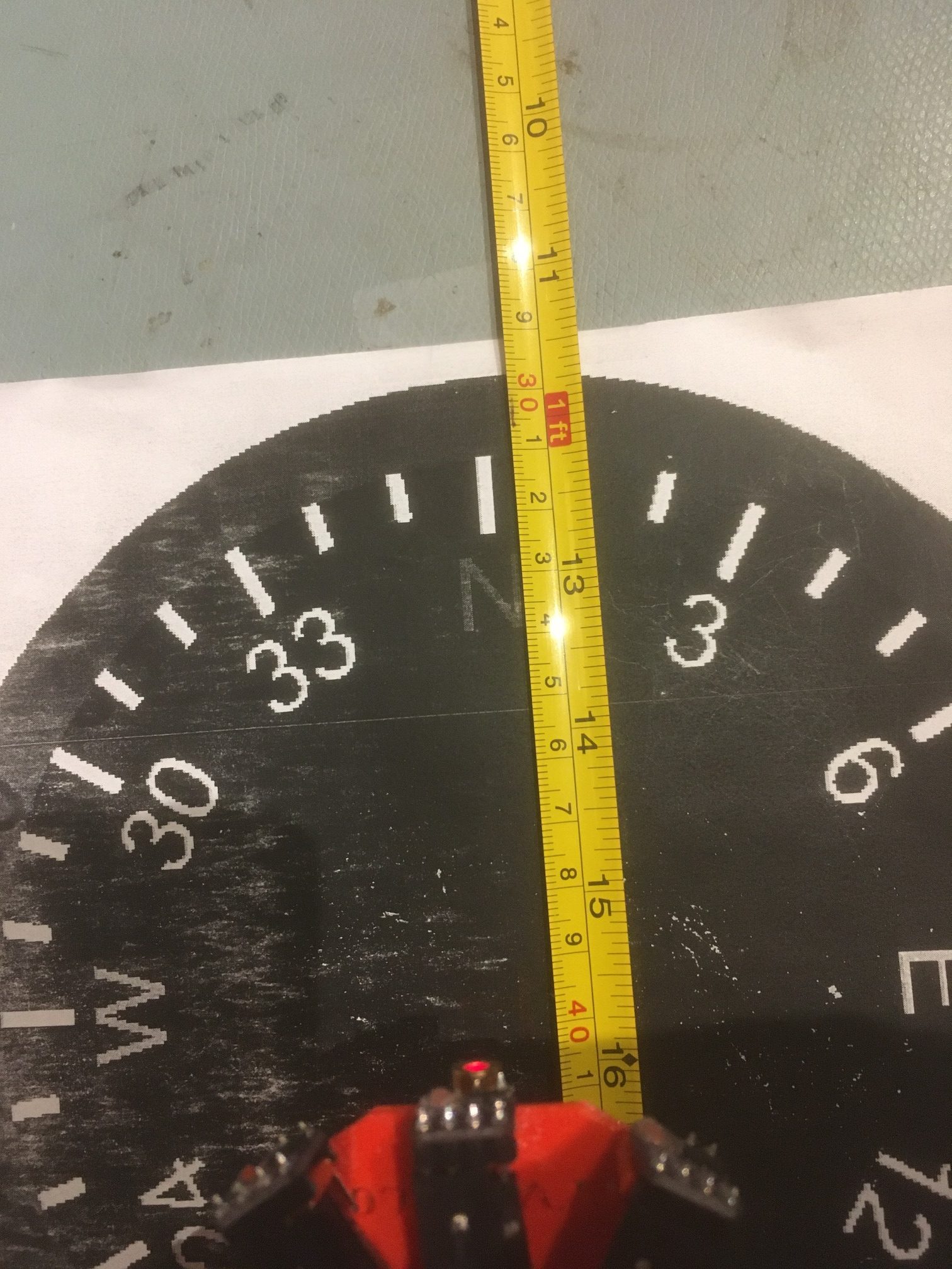
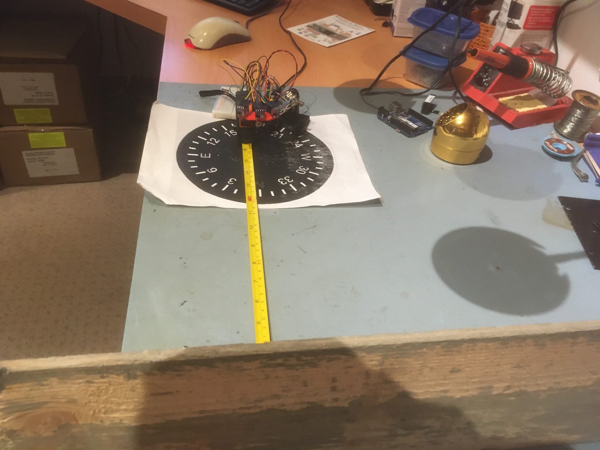
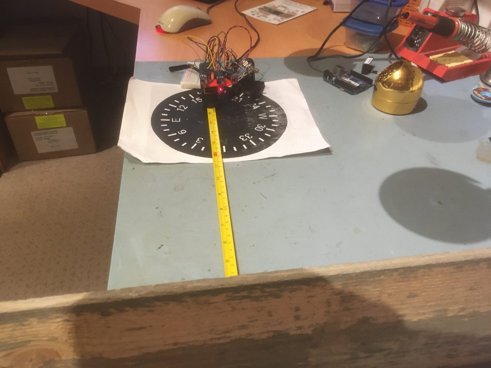
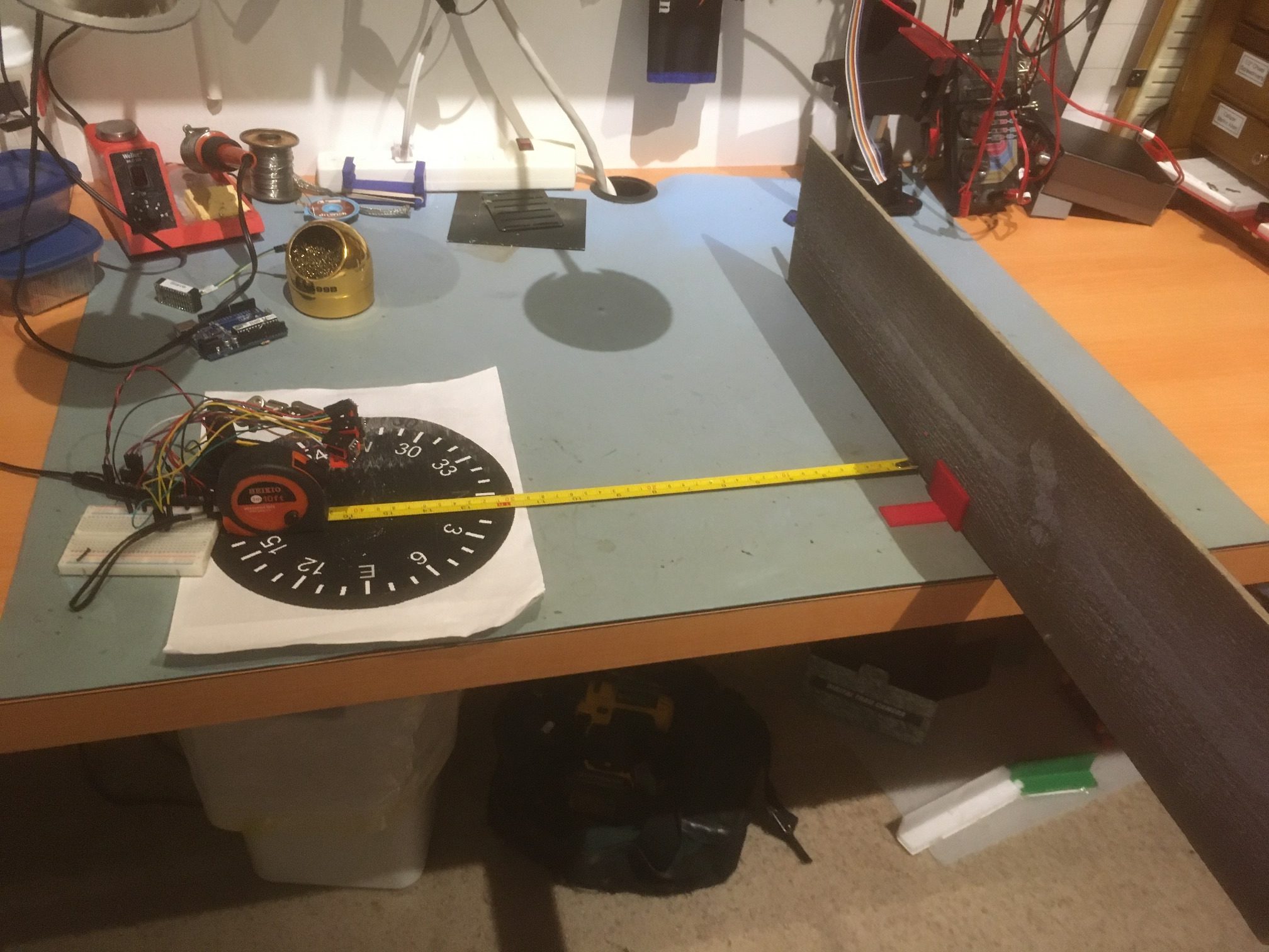
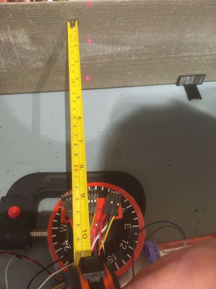
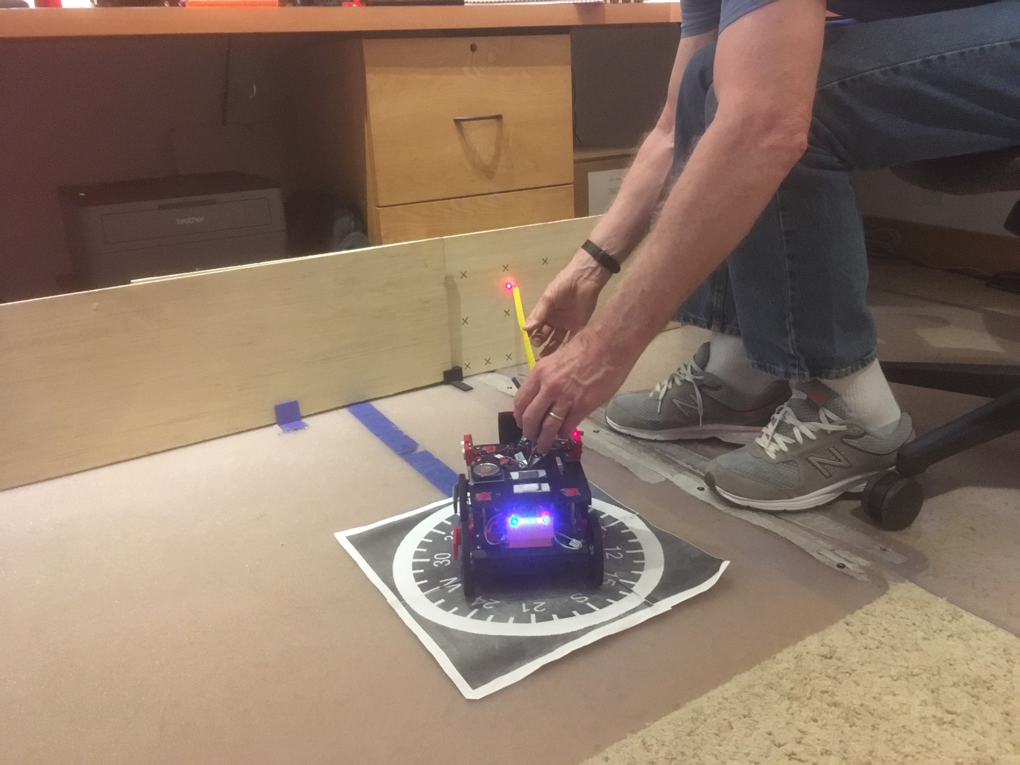
Here’s the physical setup for the experiment (only the setup for the 20 cm offset is shown – the others are identical except for the offset).
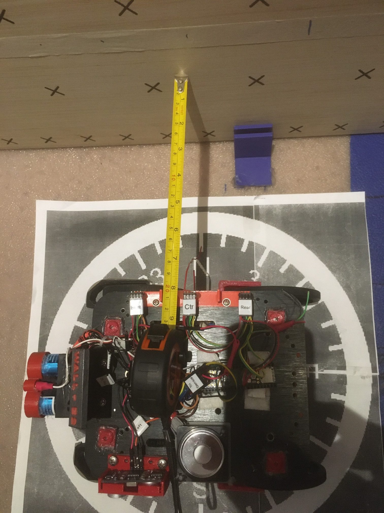
Experiment setup for 20 cm offset from target wall
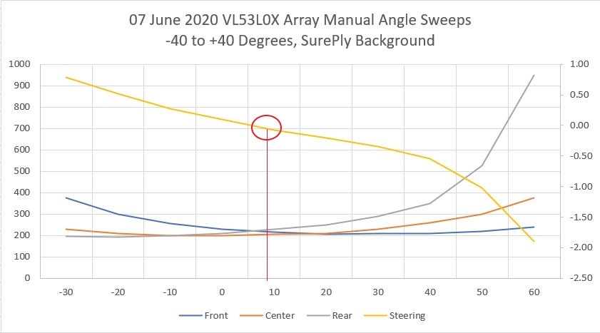
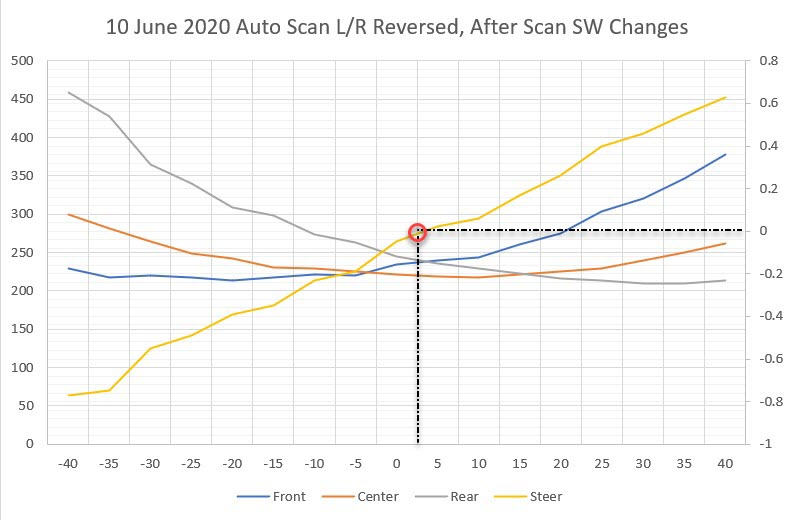
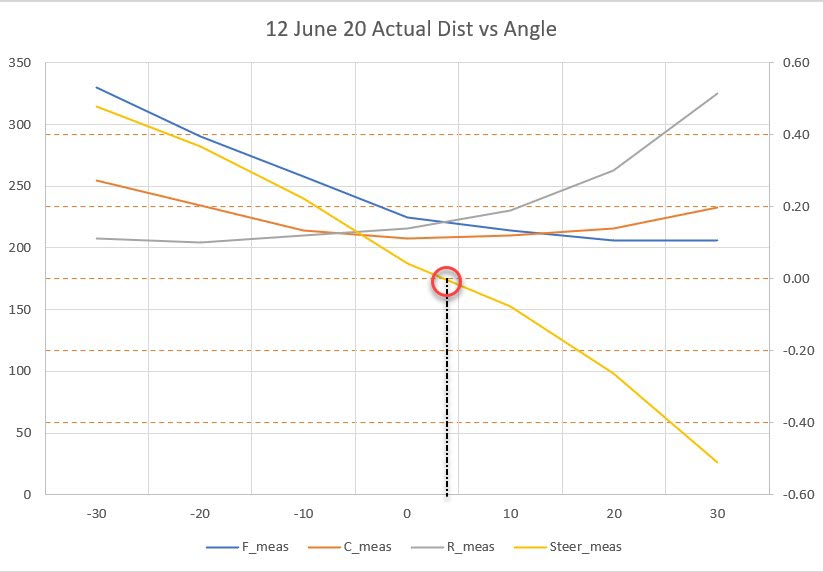
Then I recorded the three distances and steering value for -40 to +40º relative pointing angles into an Excel workbook and created the plots shown below:
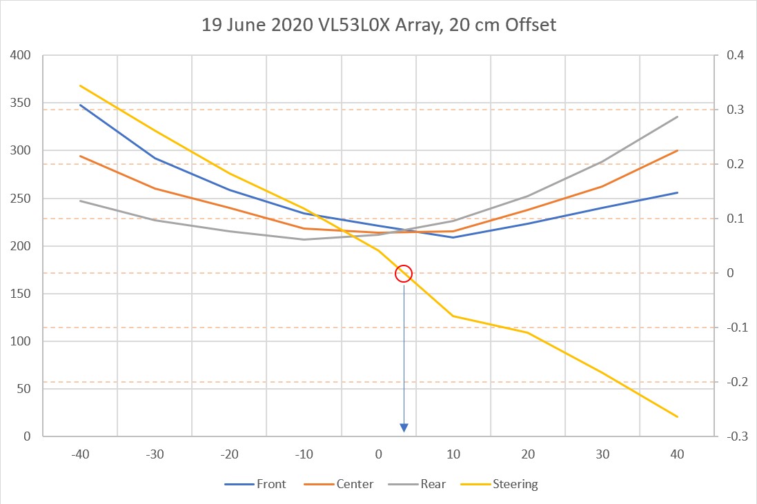
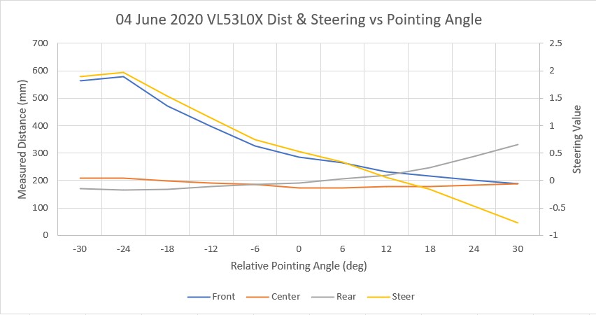
Array distances and steering value for 20 cm offset. Note steering value zero is very close to parallel orientation
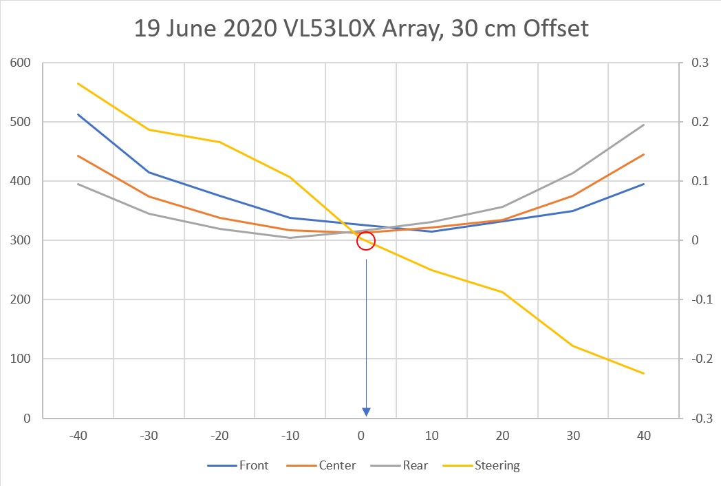
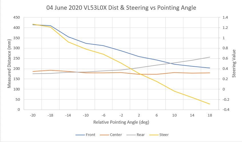
Array distances and steering value for 30 cm offset. Note steering value zero is very close to parallel orientation
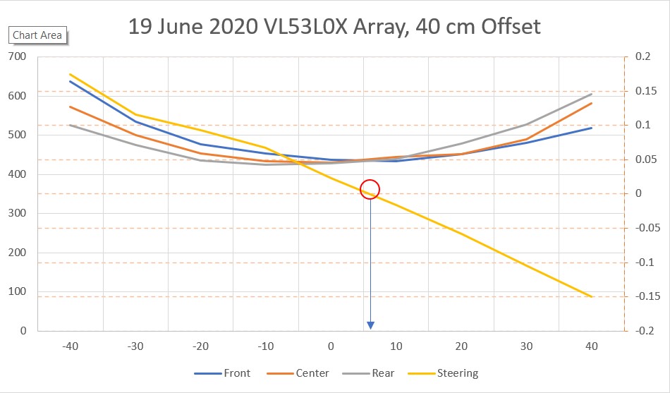
Array distances and steering value for 40 cm offset. Note steering value zero is very close to parallel orientation
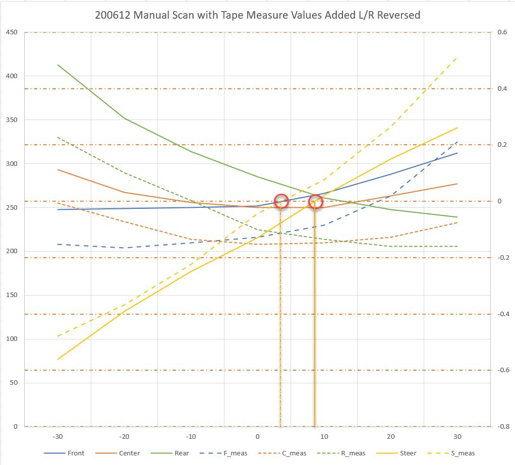
The front, center, and rear distance and steering value plots all look very similar from 20-40 cm offset, as one would expect. Here’s a combined distance plot of all three offset values.
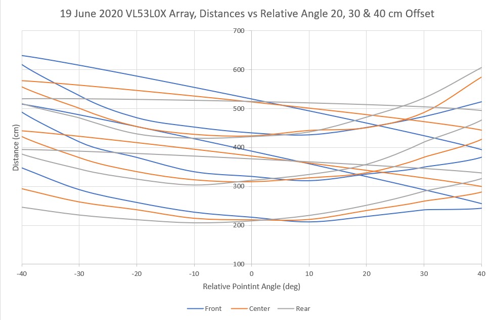
Combined distance plots for all three offsets. Note that the ‘flyback’ lines are an artifact of the plotting arrangement
In the above chart, it is clear that the curves for each offset are very similar, so an algorithm that works at one offset should also work for all offsets between 20 and 40 cm. The next chart shows the steering values for all three offsets on the same plot.
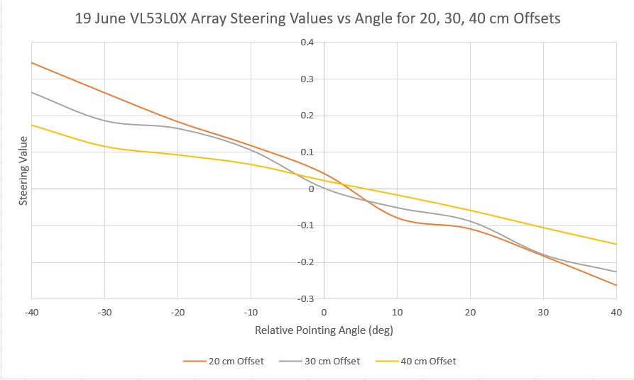
Steering values vs relative pointing angle for all three offset distances
As might be expected from the way in which the steering value is computed, i.e. (Front-Rear)/Center, the value range decreases significantly as the offset distance increases. At 20 cm the range is from -0.35 to +0.25, but for 40 cm it is only -0.18 to +0.15. So, whatever algorithm I come up with for achieving parallel orientation should be effective for the lowest range in order to be effective at all anticipated starting offsets.
To try out my new VL53L0X super-powers, I re-wrote the ‘RotateToParallelOrientation’ subroutine that attempts to rotate the robot so it is parallel to the nearest wall. The modification uses the PID engine to drive the calculated steering value from the VL53L0X sensor array to zero. After verifying that this works (quite well, actually!) I decided to modify it some more to see if I could also use the PID engine and the VL53L0X steering value to track the wall once parallel orientation was obtained. So I set up a two-stage process; the parallel orientation stage uses a PID with Kp = 800 (Ki = Kd = 0), and the tracking stage uses the same PID but with Kp set to half the parallel search value. This worked amazingly well – much better than anything I have been able to achieve to date.
The following short video is composed of two separate ‘takes’ the first one shows a ‘parallel orientation’ find operation with Kp = 800. The second one shows the effect of combining the ‘parallel find’ operation with Kp = 800 with a short segment of wall tracking with Kp = 400. As can be seen in the video, the tracking portion looks for all the world as if there were no corrections being made at all – it’s that smooth! I actually had to look through the telemetry data to verify that the tracking PID was actually making corrections to keep the steering value near zero. Here’s the video
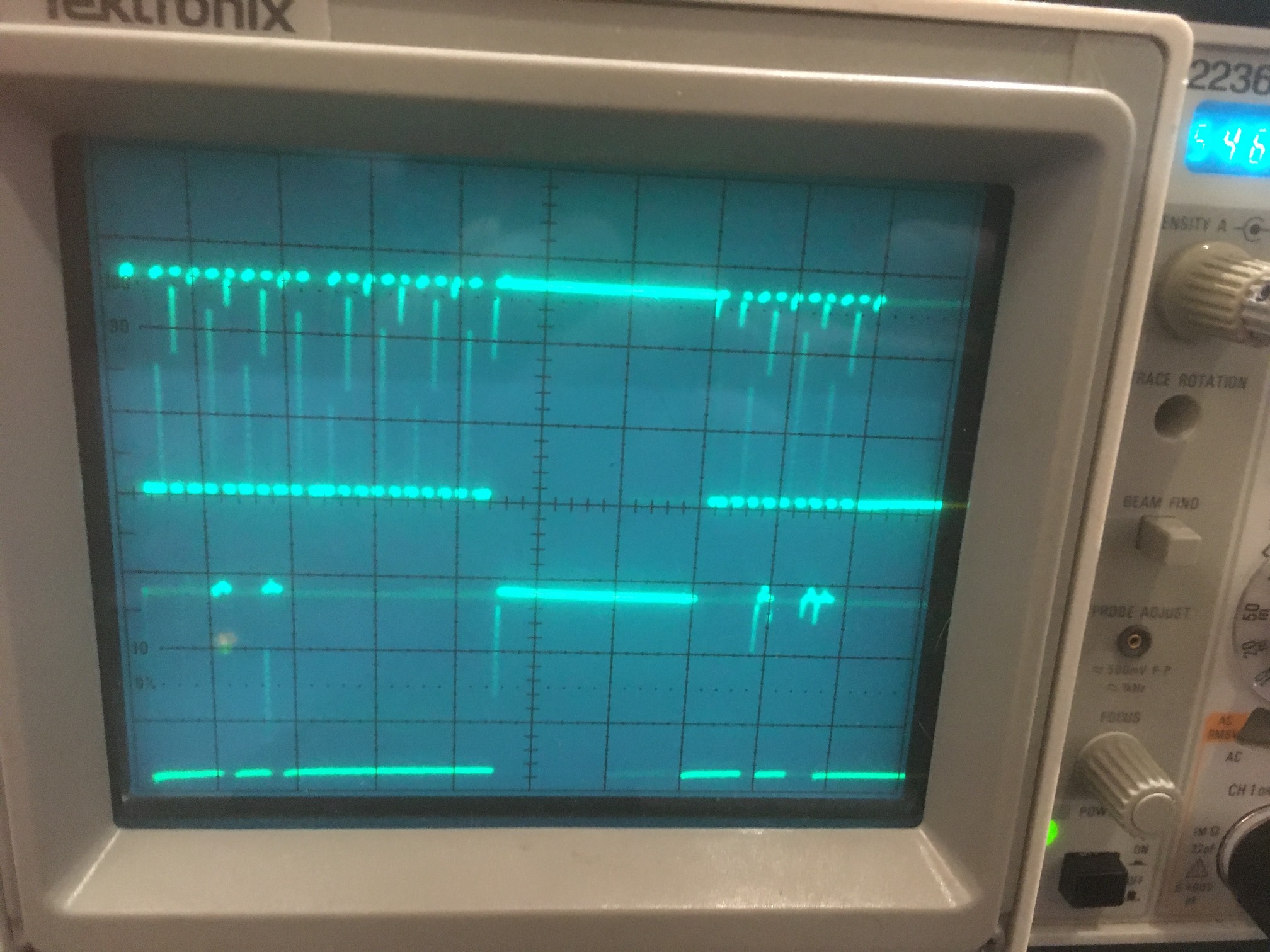
and here’s the output from the two-step ‘find parallel and track’ portion of the video
|
1 2 3 4 5 6 7 8 9 10 11 12 13 14 15 16 17 18 19 20 21 22 23 |
PID Init(): ITerm = 0.00, lastInput = 0.00 ToFArrayPID Parameters (Kp,Ki,Kd,DIR) = (800.00,0.00,0.00,1) ToFArrayPID output max/min = 255/-255 Millis PID Out Steer leftspd rightspd dist 2365 0.00 0.15 127 127 363 2562 109.45 0.19 236 17 364 2762 43.98 0.10 170 83 362 2962 4.31 0.06 131 122 343 Parallel Orientation Detected Fine Tuning ToFArrayPID Parameters (Kp,Ki,Kd,DIR) = (400.00,0.00,0.00,1) 3162 -13.02 0.02 113 140 344 3362 -13.02 0.04 113 140 342 3562 -5.96 0.04 121 132 362 3762 -2.32 0.03 124 129 349 3963 -6.25 0.03 120 133 361 4162 -8.92 0.01 118 135 361 4362 -17.78 0.01 109 144 357 4563 -3.19 0.04 123 130 369 4762 -8.08 0.03 118 135 369 4962 -13.44 0.02 113 140 366 5164 -11.16 0.02 115 138 362 5362 -8.04 0.03 118 135 368 5562 6.16 0.07 133 120 367 |
From the telemetry it can be seen that the ‘find parallel’ stage results in the robot oriented parallel to the wall at about 360 mm or so. Then in the ‘track’ stage, the ‘Steer’ value is held to within a few hundredths (0.01 to 0.07 right at the end), and the offset distance stays practically constant at 361 to 369 mm – wow!
The results of the above experiments show without a doubt that the three VL53L0X linear array is quite accurate parallel orientation and wall tracking operations – much better than anything I’ve been able to do with the ‘ping’ sensors.
The last step in this process has yet to be accomplished – showing that the setup can be used to capture a desired offset after the parallel find operation but before the wall tracking stage. Based on the work to date, I think this will be straightforward, but…..
21 June 2020 Update:
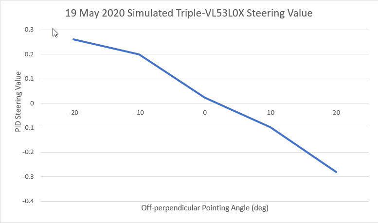
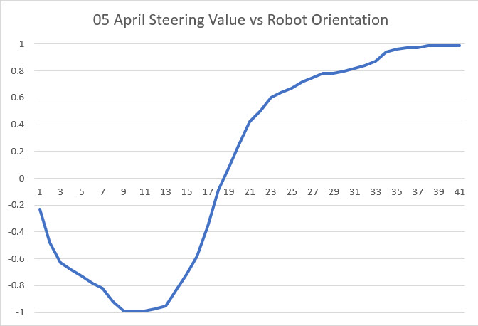
I wasn’t happy with the small range of values resulting from the above steering value computation, especially the way the value range decreased for larger offsets. So, I went back to my original data in Excel and re-plotted the data using (Front-Rear)/100 instead of (Front-Rear)/Center. This produced a much nicer set of curves, as shown in the following plot
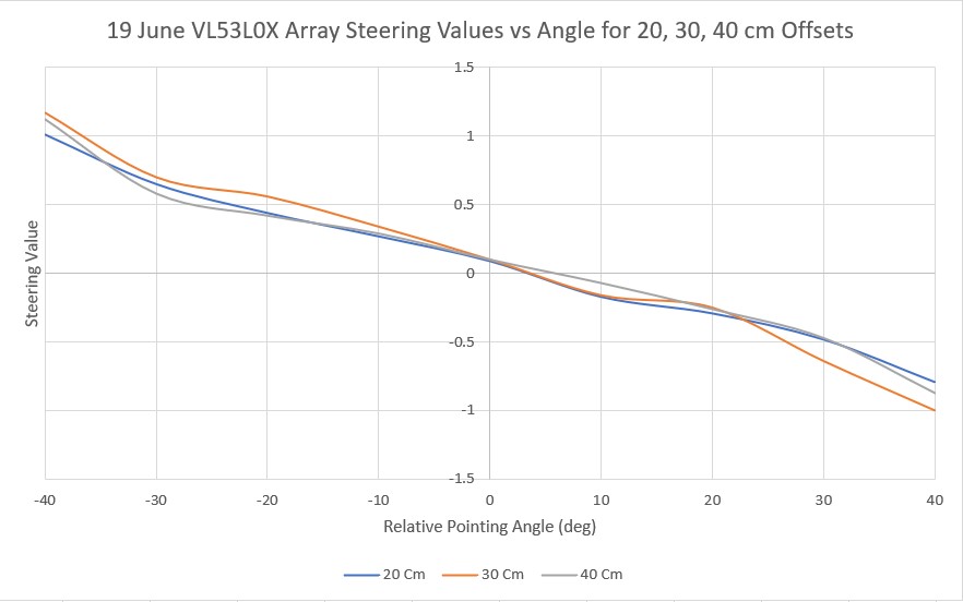
Steering values vs relative pointing angle using (Front-Rear)/100 instead of (Front-Rear)/Center
Using the above curve, I modified the program to demonstrate basic wall offset capture, as shown in the following short video
The video demonstrates a three stage wall offset capture algorithm, with delays inserted between the stages for debugging purposes. In the first stage, a PID engine is used with a very high Kp value to rotate the robot until the steering value from the VL53L0X array is near zero, denoting the parallel condition. After a 5 second delay, the PID engine Kp value is reduced to about 1/4 the ‘parallel rotate’ value, and the PID setpoint is changed to maintain a steering value that produces an approximately 20º ‘cut’ toward the desired wall offset value. In the final stage, the robot is rotated back to parallel, and the robot is stopped. In the above demonstration, the robot started out oriented about 30-40º toward the wall, about 60-70 cm from the wall. After the initial parallel rotation, the robot is located about 50 cm from the wall. In the offset capture stage, the robot moves slowly until the center VL53L0X reports about 36 cm, and then the robot rotates to parallel again, and stops the motors. At this point the robot is oriented parallel to the wall at an offset that is approximately 28 cm – not quite the desired 30 cm, but pretty close!
The next step will be to eliminate the inter-stage pauses, and instead of stopping after the third (rotate to parallel) stage, the PID engine will be used to track the resulting offset by driving the VL53L0X array steering value to zero.
23 June 2020 Update:
After nailing down the initial parallel-find, offset capture and return-to-parallel steps, I had some difficulty getting the wall tracking portion to work well. Initially I was trying to track the wall offset using the measured distance after the return-to-parallel step, and this was blowing up pretty much regardless of the PID Kp setting. After thinking about this for a while, I realized I had fallen back into the same trap I was trying to escape by going to an array of sensors rather than just one – when the robot rotates due to a tracking correction, a single distance measurement will always cause problems.
So, I went back to what I knew really worked – using all three sensor measurements to form a ‘steering value’ as follows:
|
1 |
Steering Value = Front - Rear + Center |
To complete the setup, the PID setpoint is made equal to the measured center sensor distance at the conclusion of the ‘return-to-parallel’ step. When the robot is parallel to the wall, Front = Rear = 0, so the Steering value is just the Center distance, as desired, and the PID output will drive the motors to maintain the offset setpoint. When the robot rotates, the front and rear sensors develop a difference which either adds to or subtracts from the center reading in a way that forms a reliable ‘steering value’ for the PID.
Here are a couple of short videos demonstrating all four steps; parallel-find, approach-and-capture, return-to-parallel, and wall-tracking. In the first video, the PID is set for (5,0,0) and it tracks pretty nicely. In the second video, I tried a PID set for (25,0,0) and this didn’t seem to work as well.
At this point I’m pretty satisfied with the way the 3-element VL53L0X ToF sensor array is working as a replacement for the single ultrasonic ‘ping’ sensor. The robot now has the capability to capture and track a specific offset from a nearby wall – just what I started out to do lo these many months ago.
25 June 2020 Update:
Here are a couple of short videos in my ‘outdoor’ (AKA entry hallway) range. The first video shows the response using a PID of (25,0,0) while the second one shows the same thing but with a PID value of (5,0,0).
The following Excel plot shows the steering value (in this case, just Fdist – Rdist), the corresponding PID response, and the center sensor distance measurement
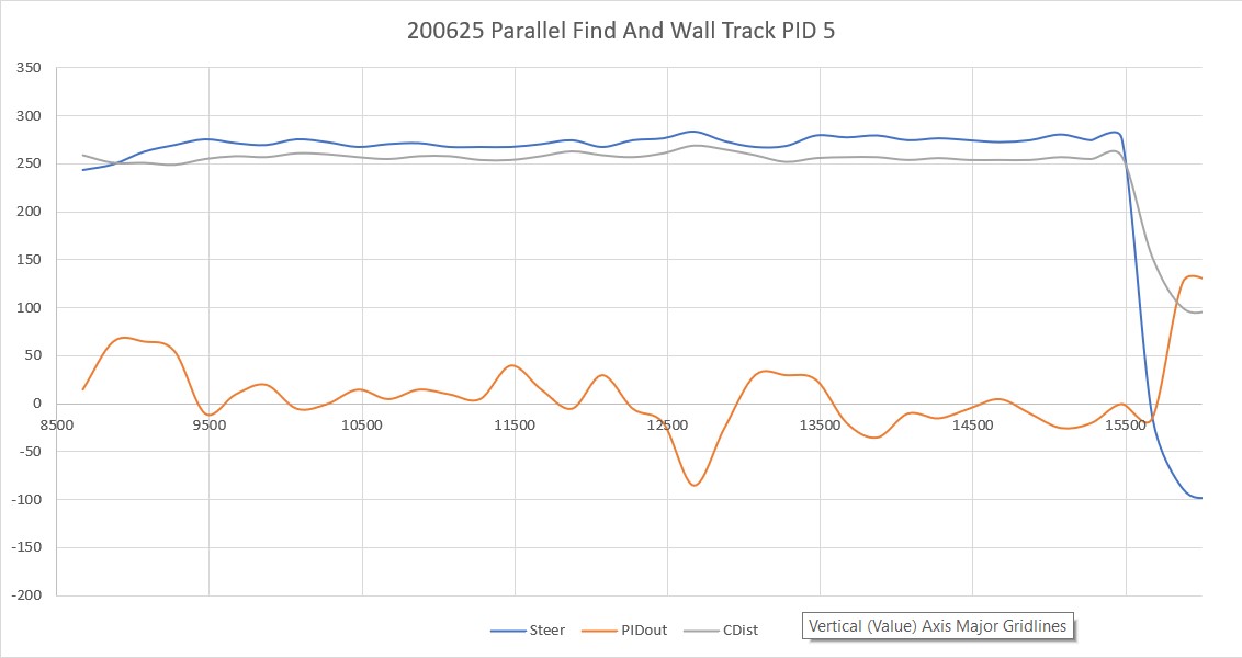
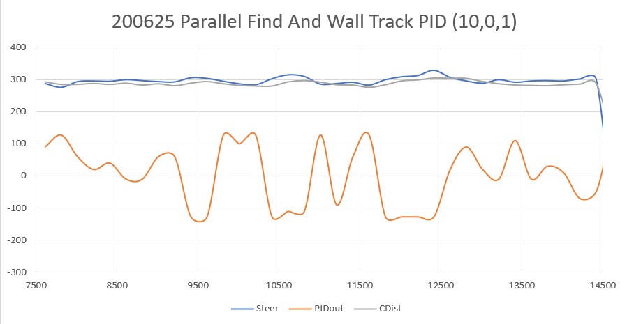
I Googled around a bit and found some information on PID tuning, including this blog post. I tried the recommended heuristic method, and wound up with a PID tuning set of (10,0,1), resulting in the following Excel plot and video
Stay tuned!
Frank