Posted 13 January 2020,
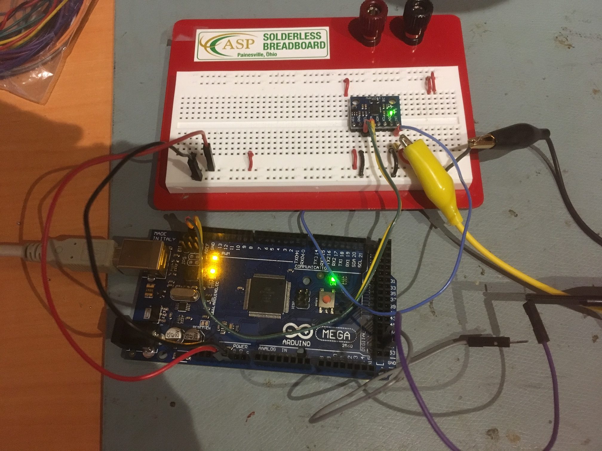
In my last post on this subject, I described my efforts to build an I2C bus sniffer using a Teensy 3.2 micro-controller. This post describes my efforts to move from a fixed array containing a 928-byte snapshot of an I2C bus conversation between an Arduino Mega 2560 and a MPU6050 IMU to a live, repeated-burst setup.
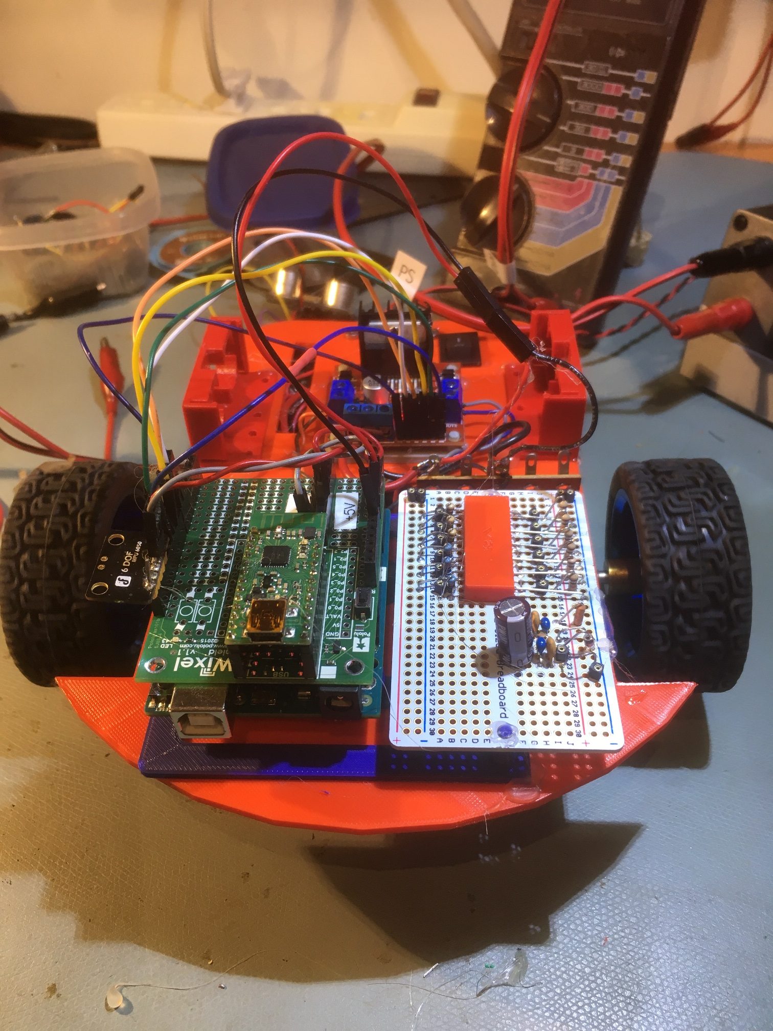
As the source for I2C traffic for the MPU6050 IMU I am using my MPU6050_MotorNoiseTest1 Arduino project with no motors or sensors connected. All the code does is ask the MPU6050 for a yaw value every 200 mSec (the value of NAV_UPDATE_INTERVAL_MSEC), as shown below:
|
1 2 3 4 5 6 7 8 9 10 11 12 13 14 15 16 17 18 19 20 21 22 23 24 25 26 27 28 29 30 |
void loop() { if (bFirstTime) { bFirstTime = false; mySerial.printf("Min\tYaw\tLDist\tRDist\n"); } if (sinceLastNavUpdateMsec >= NAV_UPDATE_INTERVAL_MSEC) { sinceLastNavUpdateMsec -= NAV_UPDATE_INTERVAL_MSEC; bool getYawResult = GetIMUHeadingDeg(); //updates global_yawval if successful if (getYawResult == 0) { if (mpu.testConnection()) { mySerial.printf("resetting IMU\n"); mpu.reset(); delay(50); } } int leftdist = GetLeftDistCm(); int rightdist = GetRightDistCm(); mySerial.printf("%3.2f\t%3.2f\t%d\t%d\n", millis()/60000.0, global_yawval, leftdist, rightdist); } } |
The Teensy code to monitor the I2C bus traffic is shown below. When I first started working with this project, I copied Kito’s I2C sniffer code, which used Teensy’s Timer1 interval timer set to produce interrupts every 1 uSec, and an ISR to capture the data. This turned out to be hard to deal with, as I couldn’t add instrumentation code to the ISR without overrunning the 1 uSec interrupt period, leading to confusing results. So, for this part of the project I disabled the Timer1 interrupt, and called the ISR directly from the loop() function. As others have pointed out, the Arduino loop() function does a lot of housekeeping in the background, so for top performance it is best to never let loop() execute, by placing another infinite loop inside loop() or inside setup(). This is what I did with the code designed to investigate whether or not the Teensy could keep up with an I2C bus running at 100Kbs.
|
1 2 3 4 5 6 7 8 9 10 11 12 13 14 15 16 17 18 19 20 21 22 23 24 25 26 27 28 29 30 31 32 33 34 35 36 37 38 39 40 41 42 43 44 45 46 47 48 49 50 51 52 53 54 55 56 57 58 59 60 61 62 63 64 65 66 67 68 69 70 71 72 73 74 75 76 77 78 79 80 81 82 83 84 85 86 87 88 89 90 91 92 93 94 95 96 97 98 99 100 101 102 103 104 105 106 107 108 109 110 111 112 113 114 115 116 117 118 119 120 121 122 123 124 125 126 127 128 129 130 131 132 133 134 135 136 137 138 139 140 141 142 143 144 145 146 147 148 149 150 151 152 153 154 155 156 157 158 159 160 161 162 163 164 165 166 167 168 169 170 171 172 173 174 175 176 177 178 179 180 181 182 183 184 185 186 187 188 189 190 191 192 193 194 195 196 197 198 199 200 |
/* Name: Teensy_I2C_Sniffer_V9.ino Created: 1/10/2020 4:15:25 PM Author: FRANKNEWXPS15\Frank */ #include <TimerOne.h> //needed for ISR const uint16_t CAPTURE_ARRAY_SIZE = 2048; const uint16_t VALID_DATA_ARRAY_SIZE = 2048; uint8_t raw_data[CAPTURE_ARRAY_SIZE]; //holds data captured from I2C bus uint8_t valid_data[VALID_DATA_ARRAY_SIZE]; //invalid bytes removed //const int WAITING_PRINT_INTERVAL_MSEC = 200;//interval timer for 'Waiting for data...' printout #define MONITOR_OUT1 2 //so can monitor ISR activity with O'scope #define MONITOR_OUT2 3 //so can monitor ISR activity with O'scope #define MONITOR_OUT3 4 //so can monitor ISR activity with O'scope #define SDA_PIN 18 #define SCL_PIN 19 //#define PARSE_LOOP_DEBUG //#define GET_8BIT_DATABYTE_DEBUG #pragma region PROCESSING_VARIABLES uint8_t devAddr; uint8_t regAddr; uint8_t databytes[2048]; //holds multiple databytes for later output sentence construction uint16_t numbytes = 0; //number of data bytes extracted from data stream int ACKNAKFlag; //can be negative uint16_t databyte_idx = 0; //index into databyte_array uint8_t killbuff[2]; //used to consume start/stop bytes elapsedMillis mSecSinceLastWaitingPrint; uint16_t numvalidbytes = 0; //number of valid bytes in this burst uint16_t read_idx = 0; //pointer to next byte pair to be processed unsigned long curMsec; unsigned long lastMsec; //added for bus direction labels enum BUSDIR { WRITE, READ, UNKNOWN = -1 } RWDir; BUSDIR BusDir = BUSDIR::UNKNOWN; //added for bus direction labels enum BUS_STATES { IDLE, //repeated 0xC/0xC ACTIVE,//0xC/0x4 transition COUNTING, //0x4/0xC transition, but 0XC count < MAC_0XC_COUNT PROCESSING //0XC count >= MAC_0XC_COUNT }; enum BUS_STATES last_State = IDLE; enum BUS_STATES BusState = IDLE; #pragma region ISR_SUPPORT volatile uint16_t write_idx = 0; volatile uint16_t BurstLength = 0; uint16_t read_index = 0; uint8_t current_portb = 0xFF; uint8_t last_portb = 0xFF; bool bBufferFull = false; uint16_t idlecount = 0; //used to detect EOM (end-of-message) //const uint16_t MAX_IDLE_COUNT = 10000; //how many idle cycles before EOM detection //const uint16_t MAX_IDLE_COUNT = 5000; //how many idle cycles before EOM detection const uint16_t MAX_IDLE_COUNT = 2500; //how many idle cycles before EOM detection //const uint16_t MAX_IDLE_COUNT = 1000; //how many idle cycles before EOM detection //const uint16_t MAX_IDLE_COUNT = 20000; //how many idle cycles before EOM detection //const uint16_t MAX_IDLE_COUNT = 30000; //how many idle cycles before EOM detection volatile bool bStartCapture = false; volatile uint16_t mult0xCCount = 0; #pragma endregion ISR Support volatile bool bDone = false; unsigned long timevals[100]; uint8_t timevalidx = 0; //------------------------------------------------------------------------------- //-------------------------------- ISR ------------------------------------ //------------------------------------------------------------------------------- //01/06/2020 modified back to capture data from SDA/SCL lines //01/09/20 modified to just capture between START & STOP void capture_data(void) { last_portb = current_portb; current_portb = GPIOB_PDIR & 12; //reads state of SDA (18) & SCL (19) at same time if (last_portb == 0xC && current_portb == 0x4) //START { digitalWriteFast(MONITOR_OUT2, HIGH); digitalWriteFast(MONITOR_OUT3, HIGH); bDone = false; mult0xCCount = 0; } else if (last_portb == 0x4 && current_portb == 0xc) //STOP { digitalWriteFast(MONITOR_OUT2, LOW); mult0xCCount = 0; } else if (mult0xCCount < MAX_IDLE_COUNT && last_portb == 0xc && current_portb == 0xc) { mult0xCCount++; if (mult0xCCount >= MAX_IDLE_COUNT) { digitalWriteFast(MONITOR_OUT3, LOW); //mult0xCCount = 0; //Serial.printf("%lu: wrote %d bytes\n", millis(),write_idx); Serial.printf("%lu\t%d\n", millis(),write_idx); bDone = true; } } if (!bDone) { digitalWriteFast(MONITOR_OUT1, HIGH); raw_data[write_idx++] = last_portb; raw_data[write_idx++] = current_portb; if (write_idx >= CAPTURE_ARRAY_SIZE) { //BurstLength = write_idx; write_idx = 0; } digitalWriteFast(MONITOR_OUT1, LOW); } } //------------------------------------------------------------------------------- //-------------------------------- END ISR --------------------------------- //------------------------------------------------------------------------------- void setup() { unsigned long now = millis(); Serial.begin(1); //rate value ignored int idx = 0; while (!Serial && (millis() - now) < 3000) { delay(500); idx++; } Serial.printf("Serial available after %lu mSec\n", millis() - now); pinMode(MONITOR_OUT1, OUTPUT); pinMode(MONITOR_OUT2, OUTPUT); pinMode(MONITOR_OUT3, OUTPUT); pinMode(LED_BUILTIN, OUTPUT); digitalWrite(MONITOR_OUT1, LOW); digitalWrite(MONITOR_OUT2, LOW); digitalWrite(MONITOR_OUT3, LOW); pinMode(SDA_PIN, INPUT); pinMode(SCL_PIN, INPUT); //reset port byte vars & start timer last_portb = current_portb = 0; write_idx = 0; memset(raw_data, 0, CAPTURE_ARRAY_SIZE); PrintNextArrayBytes(raw_data, 0, 20); //Timer1.initialize(1); // run every mico second //Timer1.attachInterrupt(capture_data); Serial.printf("mSec\tlast\tnew\tmult\tburst\n"); mSecSinceLastWaitingPrint = 0; last_State = BusState = BUS_STATES::IDLE; curMsec = millis(); lastMsec = curMsec; } void loop() { while (true) { capture_data(); } } void PrintNextArrayBytes(uint8_t* data, uint16_t startidx, uint16_t numbytes) { Serial.printf("%d bytes starting at %d: ", numbytes, startidx); for (uint16_t i = 0; i < numbytes - 1; i++) { if (i % 40 != 0) { Serial.printf("0x%x,", data[i + startidx]); } else Serial.printf("\n"); } Serial.printf("0x%x\n", data[numbytes + startidx - 1]); } |
The ‘capture_data()’ function (no longer used as an ISR) captures SCL & SDA states with a single port operation as shown
|
1 |
current_portb = GPIOB_PDIR & 12; //reads state of SDA (18) & SCL (19) at same time |
and then everything from a START pair (0xC followed by 0x4) to a STOP pair (0X4 followed by 0xC) inclusive is captured in the raw_data array.
Any I2C Sniffer project like this one assumes that I2C activity occurs in short bursts with fairly long pauses in between. This is certainly the case with my robot project, as yaw data is only acquired every 200 mSec. However, there is still the problem of determining when a I2C ‘burst’ has finished so the sniffer program can decode and print the results from the last burst. In my investigation, it became clear that at the end of the burst both the SDA line goes HIGH and stays that way until the next START condition (a 0XC followed by a 0X4). So then the question becomes “how many 0XC/0XC pairs do I have to wait before determining that the last burst is over?”
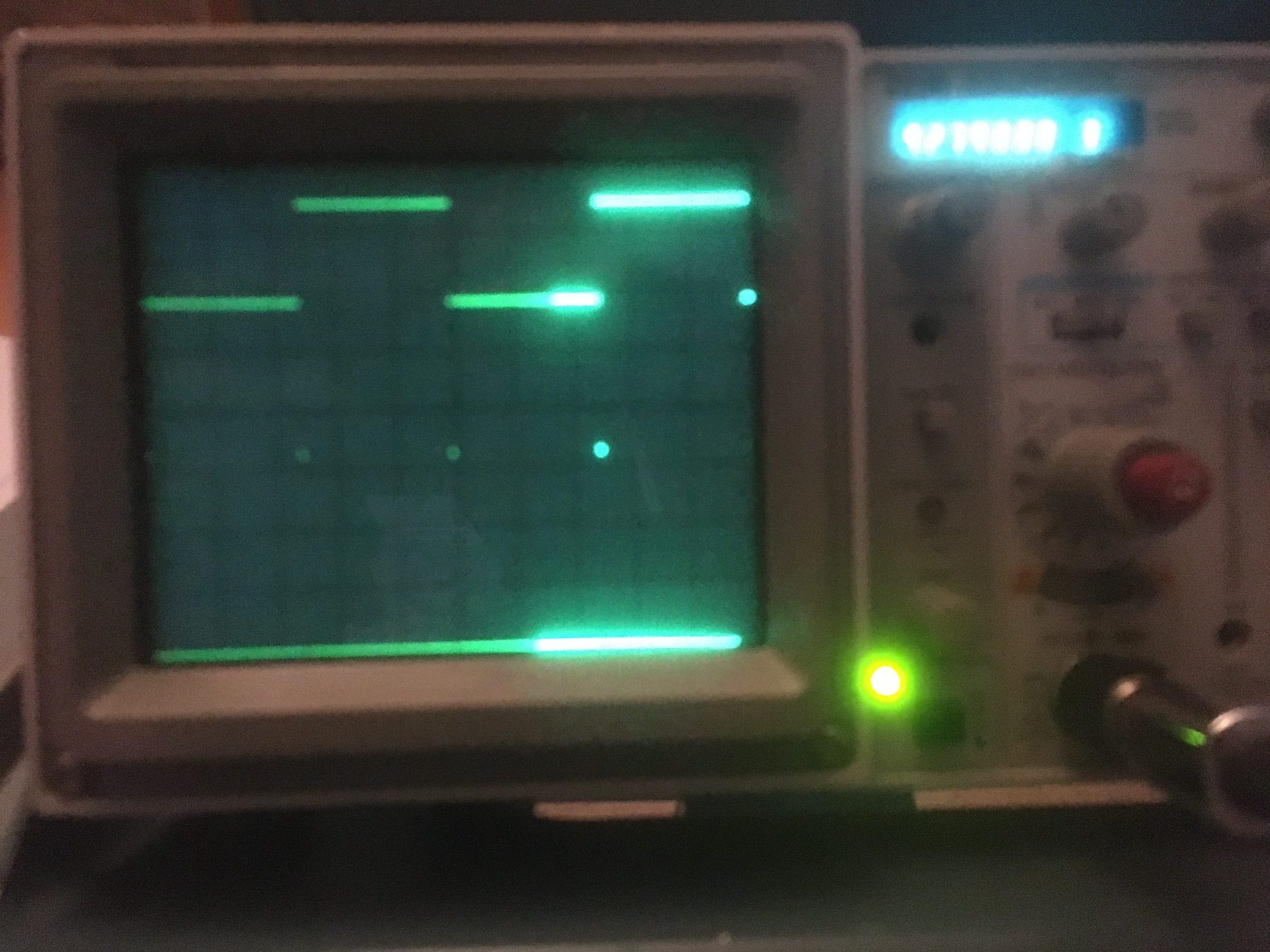
In order to answer this question I decided to use my trusty Tektronix 2236 O’Scope and Teeny’s ‘digitalReadFast’ and ‘digitalWriteFast’ functions to implement a hardware-based timing capability using Teensy pins 0,1, and 2 (MONITOR_OUT1, 2 & 3 respectively). Among other things, this allowed me to definitively determine that a ‘idle’ (0XC/0XC) count of 1000 was too small, but an idle count of 2500 was plenty, without consuming too much of the available processing time. It also turned out that ‘idle’ counts all the way up to 30,000 work too, but leave less time for processing.
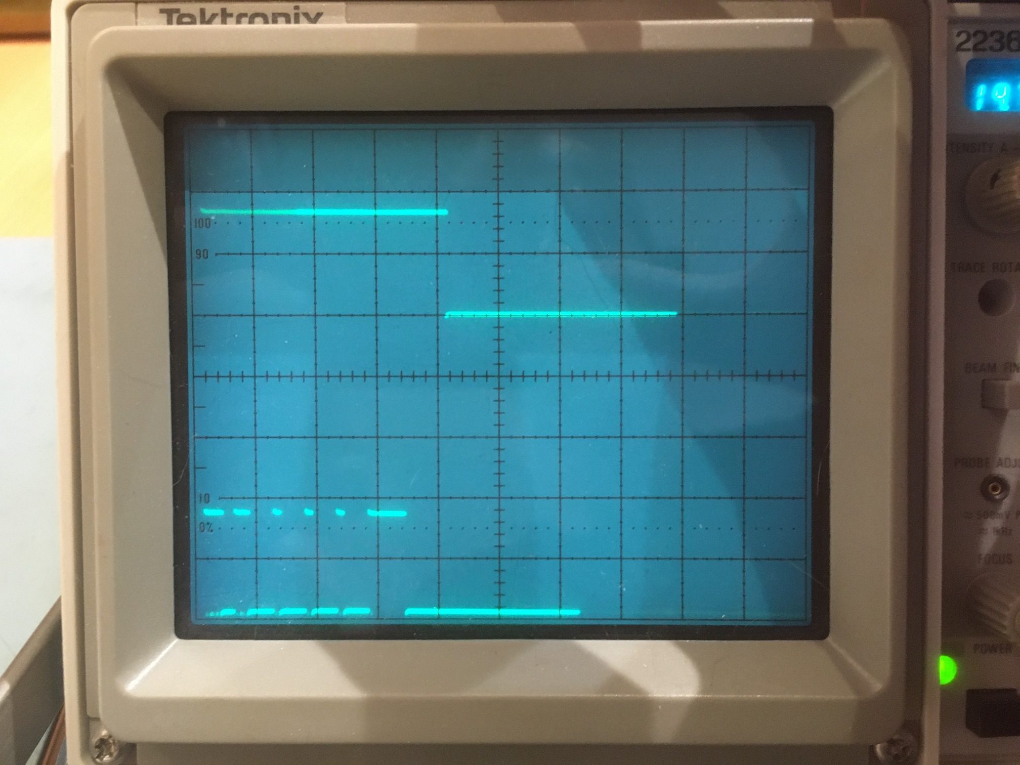
O’Scope shot showing I2C traffic on the bottom trace, and the point at which 2500 0xC/0xC (Idle) pairs is reached on the top trace (the high-to-low transition)
As can be seen in the above photo, the I2C ‘sentence’ lasts about 15 mSec, and the ‘idle’ condition is detected about 5 mSec later for a total of about 20 mSec out of the nominal 200 mSec cycle time for my robot application. This leaves about 190 mSec for I2C sentence processing and display.
18 January 2020 Update:
Success!! I now have a working Teensy 3.2 I2C Sniffer program that can continuously monitor the I2C traffic between my Arduino Mega test program acting as a I2C master and a MPU6050 IMU I2C slave. The Teensy code is available on my GitHub account here.
A major challenge in creating the sniffer program was the requirement to sample the I2C SCL & SDA lines quickly enough to accurately detect the line transitions denoting all the different I2C signals. With the I2C bus running at 100Kbs, SCL (clock) transitions occur every 5 uSec. Good sampling requires at least 2 and preferably more samples per SCL state. As noted above, I started off by copying the ISR routine from Kito’s I2C sniffer, but discovered I needed to add some logic to zero in on the desired I2C bus states (IDLE, START, DATA & STOP), and the additional code made the ISR take more than the desired 1 uSec window. After posting about this problem to Paul Stoffregen’s Teensy forum, I got some good pointers for speedup, incuding a post that mentioned the Teensy FASTRUN macro that runs functions from RAM rather than FLASH. As it turned out, adding this macro to the program allowed me to reduce the ISR cycle time from about 1.4 uSec to about .89 uSec – yay! The final ISR routine is shown below:
|
1 2 3 4 5 6 7 8 9 10 11 12 13 14 15 16 17 18 19 20 21 22 23 24 25 26 27 28 29 30 31 32 33 34 35 36 37 38 39 40 41 42 43 44 45 46 47 48 49 50 51 52 53 54 55 56 57 58 59 60 61 62 |
//------------------------------------------------------------------------------- //-------------------------------- ISR ------------------------------------ //------------------------------------------------------------------------------- FASTRUN void capture_data() //void capture_data() { last_portb = current_portb; current_portb = GPIOB_PDIR & 12; //reads state of SDA (18) & SCL (19) at same time if (!bDone && last_portb != current_portb) { mult0xCCount = 0; //reset IDLE counter digitalWriteFast(MONITOR_OUT1, HIGH); //01/17/20: joepasquariello suggestion last_current = (last_portb << 4) | (current_portb); bIsStart = (last_current == 0xC4); bIsStop = (last_current == 0x4C); bIsData = (last_current == 0x04) || (last_current == 0x8C); if (bIsStart) //START { digitalWriteFast(MONITOR_OUT2, HIGH); if (bWaitingForStart) { digitalWriteFast(MONITOR_OUT3, HIGH); //start of entire capture bWaitingForStart = false; } } else if (bIsStop) //STOP { digitalWriteFast(MONITOR_OUT2, LOW); } if (!bWaitingForStart && (bIsData || bIsStart || bIsStop)) { //digitalWriteFast(MONITOR_OUT3, HIGH); raw_data[write_idx] = last_portb; write_idx++; raw_data[write_idx] = current_portb; write_idx++; if (write_idx >= CAPTURE_ARRAY_SIZE) { bDone = true; digitalWriteFast(MONITOR_OUT3, LOW); } } digitalWriteFast(MONITOR_OUT1, LOW); } else if (!bDone && mult0xCCount < MAX_IDLE_COUNT && last_portb == 0xc && current_portb == 0xc) { mult0xCCount++; if (mult0xCCount >= MAX_IDLE_COUNT) { digitalWriteFast(MONITOR_OUT3, LOW); bDone = true; } } } //------------------------------------------------------------------------------- //-------------------------------- END ISR --------------------------------- //------------------------------------------------------------------------------- |
Note the use of digitalWriteFast() calls to output timing pulses on Teensy hardware pins so I could use my trusty Tek 2236 100 MHz O’scope to verify proper timing.
Once I got the ISR running properly, then I focused on getting the data parsing algorithm integrated into the program. I had previously shown that I could correctly parse simulated I2C traffic, so all the current challenge was to integrate the algorithm in a way that allowed continuous capture-decode-print cycles at at rate that could keep up with the desired 5 measurements/sec rate. So, I instrumented the sniffer program to display the decoded IMU traffic, along with the calculated yaw value and the time required to perform the decode.
Here’s a short section of the printout from the test program, showing the time (in minutes), the yaw (relative heading ) value retrieved from the IMU, and left/right ping distances (unused in this application).
|
1 2 3 4 5 6 7 8 9 10 11 12 13 14 15 16 17 18 19 20 |
Min Yaw LDist RDist 0.72 4.15 200 200 0.72 4.15 200 200 0.73 4.14 200 200 0.73 4.14 200 200 0.73 4.14 200 200 0.74 4.14 200 200 0.74 4.14 200 200 0.74 4.14 200 200 0.75 4.14 200 200 0.75 4.14 200 200 0.75 4.13 200 200 0.76 4.13 200 200 0.76 4.13 200 200 0.76 4.13 200 200 0.77 4.13 200 200 0.77 4.13 200 200 0.77 4.13 200 200 0.78 4.13 200 200 0.78 4.13 200 200 |
And here is the corresponding output from the I2C sniffer program
|
1 2 3 4 5 6 7 8 9 10 11 12 13 14 15 16 17 18 19 20 21 22 23 24 25 26 27 28 29 30 31 32 33 34 35 36 37 38 39 40 41 42 43 44 45 46 47 48 49 50 51 52 53 54 55 56 57 58 59 60 61 62 63 64 65 66 67 68 69 70 71 72 73 74 75 76 77 78 79 80 81 82 83 84 85 86 87 88 89 90 91 92 |
Opening port Port open Serial available after 500 mSec 4922 I2C(69) reading 2 bytes from 72... 2 14 . Done 4922 I2C(69) reading 1 bytes from 6a... c0 . Done 4922 I2C(69) writing 1 bytes to 6a... c4 . Done 4922 I2C(69) reading 2 bytes from 72... 0 0 . Done 4923 I2C(69) reading 2 bytes from 72... 0 0 . Done 4923 I2C(69) reading 2 bytes from 72... 0 0 . Done 4923 I2C(69) reading 2 bytes from 72... 0 0 . Done 4923 I2C(69) reading 2 bytes from 72... 0 1c . Done 4923 I2C(69) reading 28 bytes from 74... 3f ce 5d a1 fb b4 7e 27 0 db 6e 91 fd a2 4a 16 fe e4 f7 76 3f f0 ff ff ff fe ff fd yawval = 4.13 4922: processed = 1326 elements in 2 mSec 5103: Waiting for Data... 5122 I2C(69) reading 2 bytes from 72... 2 14 . Done 5122 I2C(69) reading 1 bytes from 6a... c0 . Done 5122 I2C(69) writing 1 bytes to 6a... c4 . Done 5122 I2C(69) reading 2 bytes from 72... 0 0 . Done 5122 I2C(69) reading 2 bytes from 72... 0 0 . Done 5123 I2C(69) reading 2 bytes from 72... 0 0 . Done 5123 I2C(69) reading 2 bytes from 72... 0 0 . Done 5123 I2C(69) reading 2 bytes from 72... 0 1c . Done 5123 I2C(69) reading 28 bytes from 74... 3f ce 5b d2 fb b4 5c 1b 0 da e8 1b fd a2 26 70 fe 86 f7 20 3f 3e 0 0 0 0 0 0 yawval = 4.13 5122: processed = 1326 elements in 2 mSec 5303: Waiting for Data... 5322 I2C(69) reading 2 bytes from 72... 2 14 . Done 5322 I2C(69) reading 1 bytes from 6a... c0 . Done 5322 I2C(69) writing 1 bytes to 6a... c4 . Done 5322 I2C(69) reading 2 bytes from 72... 0 0 . Done 5322 I2C(69) reading 2 bytes from 72... 0 0 . Done 5322 I2C(69) reading 2 bytes from 72... 0 0 . Done 5323 I2C(69) reading 2 bytes from 72... 0 0 . Done 5323 I2C(69) reading 2 bytes from 72... 0 1c . Done 5323 I2C(69) reading 28 bytes from 74... 3f ce 54 aa fb b4 42 d4 0 db 4d a7 fd a1 b8 30 fe 7e f7 72 3f 74 0 0 0 0 ff fe yawval = 4.14 5322: processed = 1326 elements in 2 mSec 5504: Waiting for Data... 5520 I2C(69) reading 2 bytes from 72... 2 14 . Done 5520 I2C(69) reading 1 bytes from 6a... c0 . Done 5520 I2C(69) writing 1 bytes to 6a... c4 . Done 5520 I2C(69) reading 2 bytes from 72... 0 0 . Done 5521 I2C(69) reading 2 bytes from 72... 0 0 . Done 5521 I2C(69) reading 2 bytes from 72... 0 0 . Done 5521 I2C(69) reading 2 bytes from 72... 0 1c . Done 5521 I2C(69) reading 28 bytes from 74... 3f ce 4e 97 fb b3 f9 2c 0 db 4f 8f fd a1 9a d9 fe 90 f7 22 3f 3c ff ff ff ff ff fd yawval = 4.14 5520: processed = 1224 elements in 2 mSec 5704: Waiting for Data... 5720 I2C(69) reading 2 bytes from 72... 2 14 . Done 5720 I2C(69) reading 1 bytes from 6a... c0 . Done 5720 I2C(69) writing 1 bytes to 6a... c4 . Done 5720 I2C(69) reading 2 bytes from 72... 0 0 . Done 5720 I2C(69) reading 2 bytes from 72... 0 0 . Done 5720 I2C(69) reading 2 bytes from 72... 0 0 . Done 5721 I2C(69) reading 2 bytes from 72... 0 1c . Done 5721 I2C(69) reading 28 bytes from 74... 3f ce 3b 8f fb b2 cf a3 0 db bd 9a fd a1 de 18 fe 84 f7 3a 3f 6e 0 0 0 1 ff ff yawval = 4.14 5720: processed = 1224 elements in 1 mSec 5903: Waiting for Data... 5920 I2C(69) reading 2 bytes from 72... 2 14 . Done 5920 I2C(69) reading 1 bytes from 6a... c0 . Done 5920 I2C(69) writing 1 bytes to 6a... c4 . Done 5920 I2C(69) reading 2 bytes from 72... 0 0 . Done 5920 I2C(69) reading 2 bytes from 72... 0 0 . Done 5920 I2C(69) reading 2 bytes from 72... 0 0 . Done 5920 I2C(69) reading 2 bytes from 72... 0 1c . Done 5921 I2C(69) reading 28 bytes from 74... 3f ce 3f 14 fb b3 1f ee 0 dc 35 23 fd a1 d6 7e fe a6 f7 7c 3f 2c ff fe ff fd 0 0 yawval = 4.13 5919: processed = 1224 elements in 2 mSec 6104: Waiting for Data... 6120 I2C(69) reading 2 bytes from 72... 2 14 . Done 6121 I2C(69) reading 1 bytes from 6a... c0 . Done 6121 I2C(69) writing 1 bytes to 6a... c4 . Done 6121 I2C(69) reading 2 bytes from 72... 0 0 . Done 6121 I2C(69) reading 2 bytes from 72... 0 0 . Done 6121 I2C(69) reading 2 bytes from 72... 0 0 . Done 6121 I2C(69) reading 2 bytes from 72... 0 1c . Done 6121 I2C(69) reading 28 bytes from 74... 3f ce 36 df fb b2 93 7 0 db 6c 5b fd a1 b0 7a fe 72 f7 54 3f a2 0 0 0 0 0 0 yawval = 4.14 6120: processed = 1224 elements in 2 mSec 6304: Waiting for Data... 6320 I2C(69) reading 2 bytes from 72... 2 14 . Done 6320 I2C(69) reading 1 bytes from 6a... c0 . Done 6320 I2C(69) writing 1 bytes to 6a... c4 . Done 6321 I2C(69) reading 2 bytes from 72... 0 0 . Done 6321 I2C(69) reading 2 bytes from 72... 0 0 . Done 6321 I2C(69) reading 2 bytes from 72... 0 0 . Done 6321 I2C(69) reading 2 bytes from 72... 0 1c . Done 6321 I2C(69) reading 28 bytes from 74... 3f ce 40 75 fb b2 dc d1 0 db 56 f8 fd a2 24 ff fe be f7 64 3f 4c 0 1 0 1 0 1 yawval = 4.13 6320: processed = 1224 elements in 2 mSec |
In the above printout, each printout shows the individual transmit & receive ‘sentences’ to/from the IMU, and the 28-byte packet received from the IMU containing, among other things, the values required to calculate a yaw (relative heading value). As can be seen, the yaw value calculated from the received bytes, closely matches the yaw values retrieved using the test program. In addition the last line of each section of the readout shows the time tag for the start of the decode process, and the total time taken to decode all the bytes in that particular burst. From the data, it is clear that only 1-2 mSec is required to decode and display a full burst.
The complete I2C Sniffer program is available on my GitHub site here. The complete test program that obtains a yaw value from the IMU every 200 mSec is shown below:
|
1 2 3 4 5 6 7 8 9 10 11 12 13 14 15 16 17 18 19 20 21 22 23 24 25 26 27 28 29 30 31 32 33 34 35 36 37 38 39 40 41 42 43 44 45 46 47 48 49 50 51 52 53 54 55 56 57 58 59 60 61 62 63 64 65 66 67 68 69 70 71 72 73 74 75 76 77 78 79 80 81 82 83 84 85 86 87 88 89 90 91 92 93 94 95 96 97 98 99 100 101 102 103 104 105 106 107 108 109 110 111 112 113 114 115 116 117 118 119 120 121 122 123 124 125 126 127 128 129 130 131 132 133 134 135 136 137 138 139 140 141 142 143 144 145 146 147 148 149 150 151 152 153 154 155 156 157 158 159 160 161 162 163 164 165 166 167 168 169 170 171 172 173 174 175 176 177 178 179 180 181 182 183 184 185 186 187 188 189 190 191 192 193 194 195 196 197 198 199 200 201 202 203 204 205 206 207 208 209 210 211 212 213 214 215 216 217 218 219 220 221 222 223 224 225 226 227 228 229 230 231 232 233 234 235 236 237 238 239 240 241 242 243 244 245 246 247 248 249 250 251 252 253 254 255 256 257 258 259 260 261 262 263 264 265 266 267 268 269 270 271 272 273 274 275 276 277 278 279 280 281 282 283 284 285 286 287 288 289 290 291 292 293 294 295 296 297 298 299 300 301 302 303 304 305 306 307 308 309 310 311 312 313 314 315 316 317 318 319 320 321 322 323 324 325 326 327 328 329 330 331 332 333 334 335 336 337 338 339 340 341 342 343 344 345 346 347 348 349 350 351 352 353 354 355 356 357 358 359 360 361 362 363 364 365 366 367 368 369 370 371 372 373 374 375 376 377 378 379 380 381 382 383 384 385 386 387 388 389 390 391 392 393 394 395 396 397 398 399 400 401 402 403 404 405 406 407 408 409 410 411 412 413 414 415 416 417 418 419 420 421 422 423 424 425 426 427 428 429 430 431 432 433 434 435 436 437 438 439 440 441 442 443 444 445 446 447 448 449 450 451 452 453 454 455 456 457 458 459 460 461 462 463 464 465 466 467 468 469 470 471 472 473 474 475 476 477 478 479 480 481 482 483 484 485 486 487 488 489 490 491 492 493 494 495 496 497 498 499 500 501 502 503 504 505 506 507 508 509 510 511 512 513 514 515 516 517 518 519 520 521 522 523 524 525 526 527 528 529 530 531 532 533 |
/* Name: MPU6050_MotorNoiseTest1.ino Created: 11/10/2019 9:17:51 AM Author: FRANKWIN10\Frank */ #pragma region INCLUDES //#include <Adafruit_INA219.h> #include <elapsedMillis.h> #include <PrintEx.h> //allows printf-style printout syntax #include "MPU6050_6Axis_MotionApps_V6_12.h" //changed to this version 10/05/19 #include "I2Cdev.h" //02/19/19: this includes SBWire.h #include <NewPing.h> //added 01/15/15 #pragma endregion INCLUDES StreamEx mySerial = Serial; //added 03/18/18 for printf-style printing elapsedMillis sinceLastNavUpdateMsec; //added 10/15/18 to replace lastmillisec MPU6050 mpu(0x69); //06/23/18 chg to AD0 high addr on 2-motor robot #pragma region MOTOR_PARAMETERS //drive wheel speed parameters const int MOTOR_SPEED_FULL = 200; //range is 0-255 const int MOTOR_SPEED_MAX = 255; //range is 0-255 const int MOTOR_SPEED_HALF = 127; //range is 0-255 const int MOTOR_SPEED_LOW = 50; //added 01/22/15 const int MOTOR_SPEED_OFF = 0; //range is 0-255 const int MOTOR_SPEED_ADJ_FACTOR = 0; //chg to 40 at 5:55pm const int LEFT_SPEED_COMP_VAL_FWD = 0; //left speed compensation value const int RIGHT_SPEED_COMP_VAL_FWD = 5; //right speed compensation value const int LEFT_SPEED_COMP_VAL_REV = 0; //left speed compensation value const int RIGHT_SPEED_COMP_VAL_REV = 0; //right speed compensation value //drive wheel direction constants const boolean FWD_DIR = true; const boolean REV_DIR = !FWD_DIR; //Motor direction variables boolean bLeftMotorDirIsFwd = true; boolean bRightMotorDirIsFwd = true; int leftspeednum = MOTOR_SPEED_HALF; int rightspeednum = MOTOR_SPEED_HALF; #pragma endregion Motor Parameters #define LED_PIN 13 // (Arduino is 13, Teensy is 11, Teensy++ is 6) #pragma region DIST_HDG_MEASUREMENT_SUPPORT //misc LIDAR and Ping sensor parameters const int MIN_OBS_DIST_CM = 20; //rev 04/28/17 for better obstacle handling const int MAX_LR_DISTANCE_CM = 200; //04/19/15 now using sep parameters for front and side sensors //distance and heading running average const int LR_PING_DIST_ARRAY_SIZE = 3; //04/28/19 added to reinstate l/r dist running avg const int LR_PING_AVG_WINDOW_SIZE = 3; //added 04/28/19 so front & lr averages can differ const int HDG_RUNNING_AVG_ARRAY_SIZE = 20; //1 second byte aLeftDist[LR_PING_DIST_ARRAY_SIZE]; byte aRightDist[LR_PING_DIST_ARRAY_SIZE]; #pragma endregion Distance Measurement Support #pragma region SENSOR_PINS const int RightSensorTrigPin = 2; const int LeftSensorTrigPin = 3; const int LeftSensorEchoPin = LeftSensorTrigPin; const int RightSensorEchoPin = RightSensorTrigPin; //added 01/16/15 for NewPing support NewPing LeftPing(LeftSensorTrigPin, LeftSensorEchoPin, MAX_LR_DISTANCE_CM / 2); NewPing RightPing(RightSensorTrigPin, RightSensorEchoPin, MAX_LR_DISTANCE_CM / 2); //const int TOT_CURR_PIN = A8; #pragma endregion Sensor Pins #pragma region MOTOR_PINS //testing with a power-blocked UNO const int EnA_Pin = 11; const int In1_Pin = 10; const int In2_Pin = 9; //Right Motor const int In3_Pin = 8; const int In4_Pin = 7; const int EnB_Pin = 6; const int MOTOR_SPEED_STEP_VAL = 20; const int MAX_MOTOR_SPEED = 255; const int MIN_MOTOR_SPEED = 0; bool bMotorIsFwd = true; bool bMotorSpeedingUp = true; int MotorSpeed = 0; #pragma endregion Motor Pin Assignments #pragma region MPU6050_SUPPORT uint8_t mpuIntStatus; // holds actual interrupt status byte from MPU. Used in Homer's Overflow routine uint8_t devStatus; // return status after each device operation (0 = success, !0 = error) uint16_t packetSize; // expected DMP packet size (default is 42 bytes) uint16_t fifoCount; // count of all bytes currently in FIFO uint8_t fifoBuffer[64]; // FIFO storage buffer // orientation/motion vars Quaternion q; // [w, x, y, z] quaternion container VectorInt16 aa; // [x, y, z] accel sensor measurements VectorInt16 aaReal; // [x, y, z] gravity-free accel sensor measurements VectorInt16 aaWorld; // [x, y, z] world-frame accel sensor measurements VectorFloat gravity; // [x, y, z] gravity vector float euler[3]; // [psi, theta, phi] Euler angle container float ypr[3]; // [yaw, pitch, roll] yaw/pitch/roll container and gravity vector int GetPacketLoopCount = 0; int OuterGetPacketLoopCount = 0; //RTC/FRAM/MPU6050 status flags bool bMPU6050Ready = true; bool dmpReady = false; // set true if DMP init was successful volatile float global_yawval = 0; //updated by GetIMUHeadingDeg() const uint16_t MAX_GETPACKET_LOOPS = 100; //10/30/19 added for backup loop exit condition in GetCurrentFIFOPacket() uint8_t GetCurrentFIFOPacket(uint8_t* data, uint8_t length, uint16_t max_loops = MAX_GETPACKET_LOOPS); //prototype here so can define a default param bool bFirstTime = true; #pragma endregion MPU6050 Support const int NAV_UPDATE_INTERVAL_MSEC = 200; void setup() { Serial.begin(115200); Serial.println("Two Wheel Robot"); // join I2C bus (I2Cdev library doesn't do this automatically) Wire.begin(); Wire.setTwiMaxLoops(15000); //08/23 needed for SBWire library Wire.setClock(100000); //07/25/19 slow down I2C clock for better noise immunity //motor control PWM pins Serial.println("...Setting up Motor Control Pins..."); pinMode(EnA_Pin, OUTPUT);//set up left motor pins as outputs pinMode(In1_Pin, OUTPUT); pinMode(In2_Pin, OUTPUT); pinMode(In3_Pin, OUTPUT);//set up right motor pins as outputs pinMode(In4_Pin, OUTPUT); pinMode(EnB_Pin, OUTPUT); pinMode(LED_PIN, OUTPUT); // initialize MPU6050 added 09/03/18 Serial.println(F("Initializing MPU6050 ...")); mpu.initialize(); // verify connection Serial.println(F("Testing device connections...")); Serial.println(mpu.testConnection() ? F("MPU6050 connection successful") : F("MPU6050 connection failed")); Serial.println(F("Initializing DMP...")); devStatus = mpu.dmpInitialize(); // supply your own gyro offsets here, scaled for min sensitivity //mpu.setXGyroOffset(51); //mpu.setYGyroOffset(8); //mpu.setZGyroOffset(21); //mpu.setXAccelOffset(1150); //mpu.setYAccelOffset(-50); //mpu.setZAccelOffset(1060); //12/03/19 settings from calibration routines mpu.setXGyroOffset(58); mpu.setYGyroOffset(20); mpu.setZGyroOffset(12); mpu.setXAccelOffset(1618); mpu.setYAccelOffset(3046); mpu.setZAccelOffset(4554); // make sure it worked (returns 0 if successful) if (devStatus == 0) { //12/06/19 no longer needed; cal vals already acquired //// Calibration Time: generate offsets and calibrate our MPU6050 //mpu.CalibrateAccel(6); //mpu.CalibrateGyro(6); //Serial.println(); //mpu.PrintActiveOffsets(); // turn on the DMP, now that it's ready Serial.println(F("Enabling DMP...")); mpu.setDMPEnabled(true); // set our DMP Ready flag so the main loop() function knows it's okay to use it Serial.println(F("DMP ready! Waiting for MPU6050 drift rate to settle...")); dmpReady = true; // get expected DMP packet size for later comparison packetSize = mpu.dmpGetFIFOPacketSize(); bMPU6050Ready = true; mySerial.printf("\nMPU6050 Ready at %2.2f Sec\n", millis() / 1000.f); } else { // ERROR! // 1 = initial memory load failed // 2 = DMP configuration updates failed // (if it's going to break, usually the code will be 1) Serial.print(F("DMP Initialization failed (code ")); Serial.print(devStatus); Serial.println(F(")")); bMPU6050Ready = false; } //mySerial.printf("Starting Motors..."); //MoveAhead(MOTOR_SPEED_FULL, MOTOR_SPEED_FULL); Serial.println("Set motor speed full & FWD direction ..."); analogWrite(EnA_Pin, 255); digitalWrite(In1_Pin, LOW); digitalWrite(In2_Pin, HIGH); analogWrite(EnB_Pin, 255); digitalWrite(In3_Pin, LOW); digitalWrite(In4_Pin, HIGH); sinceLastNavUpdateMsec = 0; } void loop() { if (bFirstTime) { bFirstTime = false; mySerial.printf("Min\tYaw\tLDist\tRDist\n"); } if (sinceLastNavUpdateMsec >= NAV_UPDATE_INTERVAL_MSEC) { sinceLastNavUpdateMsec -= NAV_UPDATE_INTERVAL_MSEC; bool getYawResult = GetIMUHeadingDeg(); //updates global_yawval if successful if (getYawResult == 0) { if (mpu.testConnection()) { mySerial.printf("resetting IMU\n"); mpu.reset(); delay(50); } } int leftdist = GetLeftDistCm(); int rightdist = GetRightDistCm(); //mySerial.printf("%3.2f\t%3.2f\t%d\t%d\t%d\t%d\n", millis()/60000.0, global_yawval, getYawResult, fifoCount, GetPacketLoopCount, OuterGetPacketLoopCount); mySerial.printf("%3.2f\t%3.2f\t%d\t%d\n", millis()/60000.0, global_yawval, leftdist, rightdist); //12/06/19 commented out for now - just want constant motor speed ////change the motor speed (and maybe the direction) //if (bMotorSpeedingUp) //{ // MotorSpeed += MOTOR_SPEED_STEP_VAL; //} //else //{ // MotorSpeed -= MOTOR_SPEED_STEP_VAL; //} //if (MotorSpeed >= MAX_MOTOR_SPEED) //{ // bMotorSpeedingUp = false; //} //if (MotorSpeed <= MIN_MOTOR_SPEED) //{ // //Serial.println("Reversing Motor Direction..."); // bMotorSpeedingUp = true; // bMotorIsFwd = !bMotorIsFwd; //} ////now actually set the motor speed and direction //analogWrite(EnA_Pin, MotorSpeed); //digitalWrite(In1_Pin, bMotorIsFwd ? LOW : HIGH); //digitalWrite(In2_Pin, bMotorIsFwd ? HIGH : LOW); ////now actually set the motor speed and direction //analogWrite(EnB_Pin, MotorSpeed); //digitalWrite(In3_Pin, bMotorIsFwd ? LOW : HIGH); //digitalWrite(In4_Pin, bMotorIsFwd ? HIGH : LOW); } } #pragma region MOTOR_SUPPORT_ROUTINES void RunBothMotors(int leftspeednum, int rightspeednum) { //Purpose: Run both Motors at left/rightspeednum speeds //Inputs: // speednum = speed value (0 = OFF, 255 = full speed) //Outputs: Both Motors run for timesec seconds at speednum speed //Plan: //Notes: // 01/14/15 - added left/right speed offset for straightness compensation // 01/22/15 - added code to restrict fast/slow values // 01/24/15 - revised for continuous run - no timing // 01/26/15 - speednum modifications moved to UpdateWallFollowmyMotorspeeds() // 12/07/15 - chg args from &int to int ////DEBUG!! // mySerial.printf("In RunBothMotors(%d,%d\n", leftspeednum, rightspeednum); ////DEBUG!! SetLeftMotorSpeed(leftspeednum); SetRightMotorSpeed(rightspeednum); } //01/24/15 removed time from MoveAhead sig, added MoveAheadMsec void MoveAhead(int leftspeednum, int rightspeednum) { //Purpose: Move ahead continuously //Provenance: G. Frank Paynter and Danny Frank 01/24/2014 //Inputs: // leftspeednum = integer denoting speed (0=stop, 255 = full speed) // rightspeednum = integer denoting speed (0=stop, 255 = full speed) //Outputs: both drive Motors energized with the specified speed //Plan: // Step 1: Set forward direction for both wheels // Step 2: Run both Motors at specified speeds //Step 1: Set forward direction for both wheels SetLeftMotorDir(true); SetRightMotorDir(true); //Step 2: Run both myMotors for timsec seconds RunBothMotors(leftspeednum, rightspeednum); } void SetLeftMotorSpeed(int speed) { if (bLeftMotorDirIsFwd) { speed = speed + LEFT_SPEED_COMP_VAL_FWD; //check limits speed = (speed <= MOTOR_SPEED_MAX) ? speed : MOTOR_SPEED_MAX; speed = (speed >= MOTOR_SPEED_OFF) ? speed : MOTOR_SPEED_OFF; } else //must be REV { speed = speed + LEFT_SPEED_COMP_VAL_REV; //check limits speed = (speed <= MOTOR_SPEED_MAX) ? speed : MOTOR_SPEED_MAX; speed = (speed >= MOTOR_SPEED_OFF) ? speed : MOTOR_SPEED_OFF; } #ifndef NO_MOTORS Serial.print("Left Speed = "); Serial.println(speed); analogWrite(EnA_Pin, speed); #endif } //11/25/15 added to utilize new private member variable bRightMotorDirIsFwd void SetRightMotorSpeed(int speed) { if (bRightMotorDirIsFwd) { speed = speed + LEFT_SPEED_COMP_VAL_FWD; //check limits speed = (speed <= MOTOR_SPEED_MAX) ? speed : MOTOR_SPEED_MAX; speed = (speed >= MOTOR_SPEED_OFF) ? speed : MOTOR_SPEED_OFF; } else //must be REV { speed = speed + LEFT_SPEED_COMP_VAL_REV; //check limits speed = (speed <= MOTOR_SPEED_MAX) ? speed : MOTOR_SPEED_MAX; speed = (speed >= MOTOR_SPEED_OFF) ? speed : MOTOR_SPEED_OFF; } #ifndef NO_MOTORS Serial.print("Right Speed = "); Serial.println(speed); analogWrite(EnB_Pin, speed); #endif } void SetLeftMotorDir(boolean bIsFwdDir) { if (bIsFwdDir) { digitalWrite(In1_Pin, LOW); digitalWrite(In2_Pin, HIGH); } else //must be REV { digitalWrite(In1_Pin, HIGH); digitalWrite(In2_Pin, LOW); } bLeftMotorDirIsFwd = bIsFwdDir; } void SetRightMotorDir(boolean bIsFwdDir) { if (bIsFwdDir) { digitalWrite(In3_Pin, LOW); digitalWrite(In4_Pin, HIGH); } else //must be REV { digitalWrite(In3_Pin, HIGH); digitalWrite(In4_Pin, LOW); } bRightMotorDirIsFwd = bIsFwdDir; } #pragma endregion Motor Support Routines bool GetIMUHeadingDeg() { //Purpose: Get latest yaw (heading) value from IMU //Inputs: None. This function should only be called after mpu.dmpPacketAvailable() returns TRUE //Outputs: // returns true if successful, otherwise false // global_yawval updated on success //Plan: //Step1: check for overflow and reset the FIFO if it occurs. In this case, wait for new packet //Step2: read all available packets to get to latest data //Step3: update global_yawval with latest value //Notes: // 10/08/19 changed return type to boolean // 10/08/19 no longer need mpuIntStatus // 10/21/19 completely rewritten to use Homer's algorithm bool retval = false; int flag = GetCurrentFIFOPacket(fifoBuffer, packetSize, MAX_GETPACKET_LOOPS); //get the latest mpu packet if (flag != 0) //0 = error exit, 1 = normal exit, 2 = recovered from an overflow { // display Euler angles in degrees mpu.dmpGetQuaternion(&q, fifoBuffer); mpu.dmpGetGravity(&gravity, &q); mpu.dmpGetYawPitchRoll(ypr, &q, &gravity); //compute the yaw value global_yawval = ypr[0] * 180 / M_PI; retval = true; } return retval; } uint8_t GetCurrentFIFOPacket(uint8_t *data, uint8_t length, uint16_t max_loops) { max_loops = max(10, max_loops); //added 12/04/19 to ensure we loop at least 10 times. This really IS a hard-coded number! fifoCount = mpu.getFIFOCount(); GetPacketLoopCount = 0; //11/10/19 I have seen this fail with fifoC > 28 on occasion, so now I loop max three times OuterGetPacketLoopCount = 0; while (fifoCount != packetSize && OuterGetPacketLoopCount <= 3) { mpu.resetFIFO(); delay(1); fifoCount = mpu.getFIFOCount(); GetPacketLoopCount = 0; while (fifoCount < packetSize && GetPacketLoopCount < max_loops) { GetPacketLoopCount++; fifoCount = mpu.getFIFOCount(); delay(2); } //if we get to here, there should be exactly one packet in the FIFO OuterGetPacketLoopCount++; } if (OuterGetPacketLoopCount < 3) { mpu.getFIFOBytes(data, packetSize); return 1; } return 0; //failed to get a good packet } int GetLeftDistCm() { //Serial.print("LeftPing\t"); Serial.println(millis()); //Notes: // 04/30/17 added limit detection/correction int timeUsec = LeftPing.ping(); //Serial.print("Left Ping Usec = "); Serial.println(timeUsec); int distCm = LeftPing.convert_cm(timeUsec); //04/30/17 added limit detection/correction distCm = (distCm > 0) ? distCm : MAX_LR_DISTANCE_CM; return distCm; } //01/10/18 reverted to regular ping(). median distance function takes too long int GetRightDistCm() { //Serial.print("RightPing\t"); Serial.println(millis()); //Notes: // 04/30/17 added limit detection/correction int timeUsec = RightPing.ping(); //Serial.print("Right Ping Usec = "); Serial.println(timeUsec); int distCm = RightPing.convert_cm(timeUsec); //04/30/17 added limit detection/correction distCm = (distCm > 0) ? distCm : MAX_LR_DISTANCE_CM; return distCm; } |
The above program was intended to help me troubleshoot the intermittent MPU6050 connection failures I have been experiencing for some time now. The purpose of the new I2C sniffer project is to create a tool to log the actual I2C traffic between this program and the IMU. The idea is that when a failure occurs, I can look back through the sniffer log to see what happened; did the Arduino Mega stop transmitting requests, or did the IMU simply stop responding, or something else entirely.