Initializing Left & Right Distance Arrays...
Left Right
340 8190
329 8190
330 8190
In RotateToParallelOrientation(Left)
Parallel Orientation Achieved at 3453 with SteeringVal = 0.01
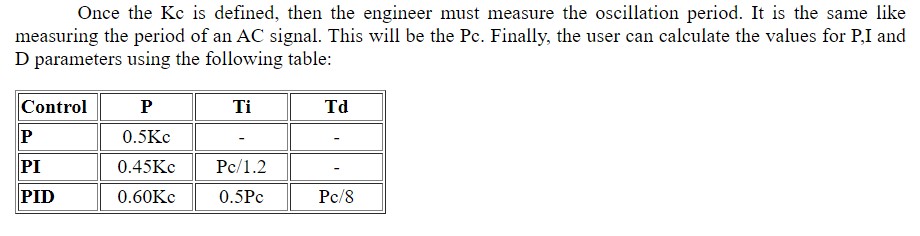
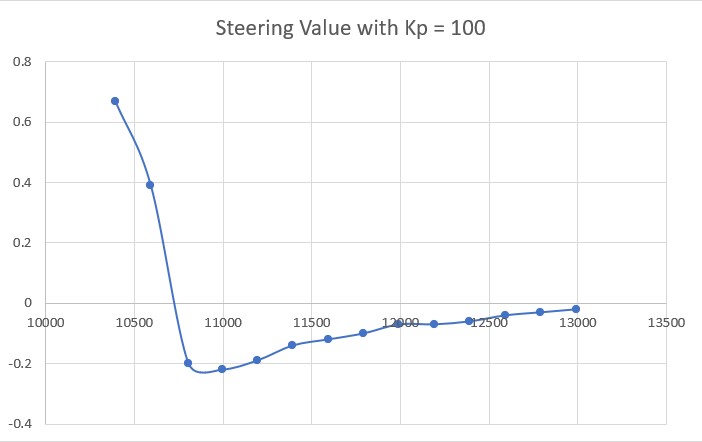
WallOffsetTrackPID Parameters (Kp,Ki,Kd) = (100,30,30)
Msec LFront LCtr LRear Front FrontVar Rear Steer Output SetPt LSpd RSpd
3464 326 334 316 175 4474.00 508 0.01 34.93 -0.30 40 109
3473 331 341 323 175 4474.00 508 -0.01 34.93 -0.30 40 109
3554 329 342 326 172 4286.29 8190 0.03 34.93 -0.30 40 109
3651 326 354 325 181 4164.85 1192 -0.01 24.80 -0.30 50 99
3750 329 354 349 127 4520.47 1114 -0.20 24.80 -0.30 50 99
3850 307 387 336 102 5186.04 1197 -0.29 -75.00 -0.30 150 0
3946 306 342 361 96 5933.30 1156 -0.55 -75.00 -0.30 150 0
4043 293 325 335 105 6564.30 1272 -0.29 -2.29 -0.25 77 72
4141 282 310 305 139 6862.29 8190 -0.23 -2.29 -0.10 77 72
4235 272 296 287 174 6912.94 914 -0.19 8.02 0.04 66 83
4330 267 284 285 172 6889.58 920 -0.18 8.02 0.16 66 83
4427 260 283 267 165 6772.68 967 -0.06 16.33 0.17 58 91
4521 249 286 270 147 6565.69 1069 -0.21 16.33 0.14 58 91
4620 248 277 268 134 6196.07 1056 -0.20 -75.00 0.23 150 0
4717 238 261 248 133 5544.52 1166 -0.10 -75.00 0.30 150 0
4812 230 243 249 126 4582.67 1046 -0.19 -48.43 0.30 123 26
4910 220 243 236 122 3231.83 974 -0.16 -48.43 0.30 123 26
5006 218 232 213 121 1415.66 1029 0.05 43.82 0.30 31 118
5105 218 246 205 119 1363.33 1169 0.13 43.82 0.30 31 118
5200 215 237 221 115 1303.73 1136 -0.06 -73.26 0.30 148 1
5300 217 227 218 113 1215.34 1190 -0.01 -21.19 0.30 96 53
5396 219 235 205 110 1098.33 1228 0.14 -21.19 0.30 96 53
5491 228 244 215 106 974.86 8190 0.19 43.48 0.30 31 118
5587 239 260 218 103 868.73 8190 0.21 43.48 0.30 31 118
5688 244 254 235 97 807.43 8190 0.09 -57.15 0.30 132 17
5783 253 268 246 94 766.78 8190 0.07 -57.15 0.30 132 17
5882 260 260 246 92 731.99 8190 0.14 -7.63 0.30 82 67
5982 282 278 257 88 697.85 8190 0.25 -7.63 0.22 82 67
6081 287 279 256 85 608.15 8190 0.30 50.64 0.21 24 125
6178 294 297 276 80 664.40 8190 0.18 50.64 0.03 24 125
6277 316 305 287 77 719.44 8190 0.11 -46.88 -0.05 121 28
6373 311 315 289 74 774.14 8190 0.22 -46.88 -0.15 121 28
6471 311 334 292 73 840.70 8190 0.25 75.00 -0.30 0 150
6569 327 344 311 68 894.32 8190 0.16 75.00 -0.30 0 150
6670 340 348 308 62 816.19 8190 0.32 75.00 -0.30 0 150
6772 342 360 333 54 737.65 8190 0.09 -31.20 -0.30 106 43
6868 354 350 333 53 657.72 8190 0.21 -31.20 -0.30 106 43
6967 338 358 326 51 634.07 8190 0.12 51.06 -0.30 23 126
7063 346 368 333 50 636.22 8190 0.13 51.06 -0.30 23 126
7161 334 346 345 44 638.78 8190 -0.11 -49.37 -0.30 124 25
7260 334 371 333 39 658.55 8190 0.01 -49.37 -0.30 124 25
7360 336 350 330 32 693.11 8190 0.06 75.00 -0.30 0 150
7457 332 357 319 25 732.13 8190 0.13 75.00 -0.30 0 150
7556 344 355 332 23 757.01 8191 0.12 62.97 -0.30 12 137
bObstacleAhead TRUE in TRACKLEFT at 7656 with frontdist 18, variance = 787.12
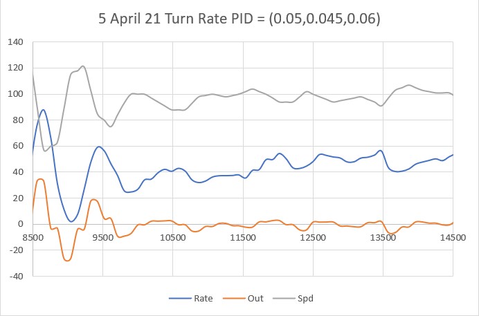
In SpinTurn(CW, 90.00)
Msec Hdg pHdg Rate TRate Spd
7751 6.06 1.38 52.1 20.0 87
7848 1.23 6.06 51.0 20.0 50
7947 -5.41 1.23 68.5 20.0 50
8045 -12.14 -5.41 70.7 20.0 50
8144 -17.56 -12.14 55.5 20.0 50
8244 -21.25 -17.56 38.0 20.0 50
8341 -23.40 -21.25 22.6 20.0 50
8438 -24.34 -23.40 9.9 20.0 90
8537 -25.11 -24.34 8.0 20.0 130
8636 -28.17 -25.11 31.4 20.0 90
8735 -35.01 -28.17 71.1 20.0 50
8835 -41.34 -35.01 65.0 20.0 50
8935 -44.53 -41.34 32.6 20.0 50
9036 -46.09 -44.53 15.8 20.0 90
9135 -47.11 -46.09 10.6 20.0 130
9233 -50.33 -47.11 33.3 20.0 90
9333 -56.48 -50.33 63.0 20.0 50
Slowing down to 10.00 deg/sec at -56.48 deg
9430 -62.64 -56.48 65.1 10.0 50
9529 -65.95 -62.64 34.4 10.0 50
9626 -66.79 -65.95 8.7 10.0 90
9723 -67.14 -66.79 3.7 10.0 130
9823 -68.64 -67.14 15.5 10.0 90
9919 -72.84 -68.64 44.8 10.0 50
10018 -76.92 -72.84 42.1 10.0 50
10116 -79.19 -76.92 23.8 10.0 50
10213 -79.30 -79.19 1.2 10.0 90
10313 -79.37 -79.30 0.7 10.0 130
10414 -80.87 -79.37 15.3 10.0 90
10417: Exiting SpinTurn() at -80.87 deg
In RotateToParallelOrientation(Left)
Parallel Orientation Achieved at 11293 with SteeringVal = 0.00
WallOffsetTrackPID Parameters (Kp,Ki,Kd) = (100,30,30)
Msec LFront LCtr LRear Front FrontVar Rear Steer Output SetPt LSpd RSpd
11304 49 69 49 101 808.15 574 0.00 -63.93 0.30 138 11
11313 45 66 46 101 808.15 574 -0.01 -63.93 0.30 138 11
11395 44 64 47 109 891.88 627 -0.03 -63.93 0.30 138 11
11492 43 65 43 162 1291.60 673 0.00 -28.83 0.30 103 46
11591 47 100 44 216 2143.29 728 0.03 -28.83 0.30 103 46
11689 47 70 81 94 2055.42 758 -0.34 -75.00 0.30 150 0
11786 52 71 45 69 1960.80 749 0.07 -75.00 0.30 150 0
11882 56 75 45 67 1851.13 701 0.11 75.00 0.30 0 150
11979 63 76 43 63 1762.12 489 0.20 75.00 0.30 0 150
12079 62 84 56 58 1678.46 534 0.06 -41.04 0.30 116 33
12176 73 89 71 54 1594.01 745 0.02 -41.04 0.30 116 33
12275 79 90 73 50 1519.21 790 0.06 -26.76 0.30 101 48
12372 85 97 74 47 1480.52 774 0.11 -26.76 0.30 101 48
12473 95 109 78 42 1477.60 619 0.17 16.85 0.30 58 91
12569 108 113 87 35 1515.29 570 0.21 16.85 0.30 58 91
12666 113 120 98 33 1561.57 639 0.15 -24.60 0.30 99 50
Hit Wall Offset Limit (30 cm) at 1769472 with frontdist = 29, Setpoint = 0.00
In StepTurn(Tracking Left)
In SpinTurn(CW, 90.00)
Msec Hdg pHdg Rate TRate Spd
12862 -109.12 -107.73 15.9 20.0 167
12961 -116.70 -109.12 78.1 20.0 127
13061 -127.75 -116.70 113.9 20.0 87
13158 -142.57 -127.75 155.6 20.0 50
13257 -155.69 -142.57 136.5 20.0 50
13355 -165.76 -155.69 106.5 20.0 50
Slowing down to 10.00 deg/sec at -165.76 deg
13453 -172.39 -165.76 69.2 10.0 50
13551 -176.13 -172.39 38.6 10.0 50
13650 -176.98 -176.13 8.9 10.0 90
13747 -177.02 -176.98 0.4 10.0 130
13845 -178.80 -177.02 18.5 10.0 90
13946 175.39 -178.80 3604.6 10.0 50
14041 169.71 175.39 61.9 10.0 50
14043: Exiting SpinTurn() at 169.71 deg
In RotateToParallelOrientation(Left)
Parallel Orientation Achieved at 14687 with SteeringVal = 0.01
WallOffsetTrackPID Parameters (Kp,Ki,Kd) = (100,30,30)
Msec LFront LCtr LRear Front FrontVar Rear Steer Output SetPt LSpd RSpd
14698 191 208 190 251 10269.92 289 0.01 -75.00 0.30 150 0
14706 196 205 195 251 10269.92 289 -0.06 -75.00 0.30 150 0
14788 198 213 196 246 10313.22 355 0.02 -75.00 0.30 150 0
14884 207 219 198 240 10143.41 402 0.09 -2.10 0.30 77 72
14983 210 226 197 232 9731.76 451 0.13 -2.10 0.30 77 72
15078 216 228 209 231 9169.12 488 0.07 -34.79 0.30 109 40
15174 223 240 214 226 8389.68 547 0.09 -34.79 0.30 109 40
15270 225 243 215 226 7483.51 576 0.10 -17.39 0.30 92 57
15366 223 244 229 224 6445.87 624 -0.06 -17.39 0.30 92 57
15462 228 245 232 221 5279.39 657 -0.01 -71.32 0.30 146 3
15558 234 254 229 217 4146.39 705 0.05 -71.32 0.30 146 3
15655 248 260 220 218 3116.80 748 0.28 75.00 0.30 0 150
15749 272 266 238 218 2207.54 794 0.34 75.00 0.30 0 150
15843 282 288 248 211 1580.34 839 0.30 17.16 0.12 57 92
15938 293 287 264 200 1231.91 877 0.29 17.16 0.13 57 92
16038 301 303 266 194 947.68 895 0.27 15.06 -0.03 59 90
16137 304 307 281 192 667.96 916 0.23 15.06 -0.07 59 90
16232 305 320 297 187 675.37 984 0.08 -34.10 -0.20 109 40
16329 321 327 294 183 719.94 1012 0.27 -34.10 -0.27 109 40
16429 326 344 301 181 748.10 1030 0.25 75.00 -0.30 0 150
16525 328 345 318 175 773.36 1061 0.10 75.00 -0.30 0 150
16623 340 350 323 171 785.28 1139 0.17 20.96 -0.30 54 95
16719 344 351 327 165 797.68 1142 0.17 20.96 -0.30 54 95
16820 355 364 357 161 809.43 1160 -0.01 -26.17 -0.30 101 48
16914 356 372 351 157 816.35 1215 0.05 -26.17 -0.30 101 48
17007 371 376 338 153 826.46 1232 0.33 75.00 -0.30 0 150
17104 365 378 350 151 828.07 1275 0.15 75.00 -0.30 0 150
17200 362 363 359 146 837.66 8190 0.03 -55.29 -0.30 130 19
17295 360 371 353 143 851.33 8190 0.07 -55.29 -0.30 130 19
17392 361 387 354 136 892.80 8190 0.07 51.82 -0.30 23 126
17488 364 368 354 134 916.39 8190 0.10 51.82 -0.30 23 126
17584 352 380 353 129 948.67 8190 -0.01 8.69 -0.30 66 83
17680 349 368 360 128 954.63 8190 -0.11 8.69 -0.30 66 83
17776 370 381 356 126 945.54 8190 0.06 61.77 -0.30 13 136
17872 362 375 362 123 929.23 8190 0.00 61.77 -0.30 13 136
17972 347 377 363 122 903.09 8190 -0.04 1.55 -0.30 73 76
18070 348 395 372 122 843.49 8190 -0.24 1.55 -0.30 73 76
18167 352 370 362 120 760.07 8190 -0.17 -20.06 -0.30 95 54
18264 332 368 353 115 694.64 8190 -0.21 -20.06 -0.30 95 54
18362 312 336 339 111 661.03 8190 -0.20 7.24 -0.30 67 82
18460 297 323 327 105 644.80 8190 -0.30 7.24 -0.23 67 82
18560 283 312 313 100 627.13 8190 -0.28 -34.24 -0.12 109 40
18655 285 302 299 96 615.78 8190 -0.14 -34.24 -0.02 109 40
18754 264 298 287 90 613.99 8190 -0.19 11.13 0.02 63 86
18850 259 276 255 86 606.39 8190 0.04 11.13 0.24 63 86
18950 252 284 259 84 601.15 8190 -0.09 9.38 0.16 65 84
19046 240 280 260 81 595.10 8190 -0.20 9.38 0.20 65 84
19144 238 252 248 78 595.94 8190 -0.10 -39.82 0.30 114 35
19240 217 253 242 76 593.76 8190 -0.13 -39.82 0.30 114 35
19338 218 246 230 71 598.99 8190 -0.09 -33.99 0.30 108 41
19438 216 236 221 67 608.08 8190 -0.10 -42.19 0.30 117 32
19535 205 225 214 61 621.04 8190 -0.09 -42.19 0.30 117 32
19634 208 222 203 55 647.83 8190 0.06 24.09 0.30 50 99
19733 208 221 203 50 677.59 8190 0.05 24.09 0.30 50 99
19832 210 230 201 48 711.95 8190 0.18 23.73 0.30 51 98
19932 224 232 214 45 739.29 8190 0.10 -44.87 0.30 119 30
20032 224 231 213 40 776.88 8190 0.10 -21.47 0.30 96 53
20130 228 235 210 37 803.67 8190 0.18 -21.47 0.30 96 53
20231 240 244 216 32 829.84 8190 0.15 -1.92 0.30 76 73
Hit Wall Offset Limit 20330 at 1835008 with frontdist = -26214, Setpoint = 0.00
In StepTurn(Tracking Left)
In SpinTurn(CW, 90.00)
Msec Hdg pHdg Rate TRate Spd
20427 170.01 171.69 18.9 20.0 167
20528 162.73 170.01 74.4 20.0 127
20628 149.44 162.73 136.8 20.0 87
20724 133.31 149.44 171.6 20.0 50
20824 118.14 133.31 156.0 20.0 50
20921 107.84 118.14 108.3 20.0 50
Slowing down to 10.00 deg/sec at 107.84 deg
21018 100.75 107.84 75.0 10.0 50
21114 96.88 100.75 41.2 10.0 50
21211 95.61 96.88 13.7 10.0 50
21304 95.40 95.61 2.2 10.0 90
21401 95.27 95.40 1.4 10.0 130
21500 92.77 95.27 26.0 10.0 90
21595 86.00 92.77 73.4 10.0 50
21597: Exiting SpinTurn() at 86.00 deg
In RotateToParallelOrientation(Left)
Parallel Orientation Achieved at 21983 with SteeringVal = -0.01
WallOffsetTrackPID Parameters (Kp,Ki,Kd) = (100,30,30)
Msec LFront LCtr LRear Front FrontVar Rear Steer Output SetPt LSpd RSpd
21994 161 185 162 108 5323.48 265 -0.01 -75.00 0.30 150 0
22002 164 182 160 108 5323.48 265 0.05 -75.00 0.30 150 0
22086 166 184 159 78 5270.27 295 0.07 -75.00 0.30 150 0
22184 175 185 165 58 5243.36 352 0.10 9.55 0.30 65 84
22280 183 190 172 175 5373.00 388 0.11 9.55 0.30 65 84
22375 197 204 176 91 5247.15 436 0.21 20.28 0.30 54 95
22470 197 215 182 108 5081.33 467 0.15 20.28 0.30 54 95
22564 207 226 189 151 4952.56 518 0.18 -25.08 0.30 100 49
22663 218 233 204 52 4842.48 555 0.14 -25.08 0.30 100 49
22761 236 245 213 141 4580.68 601 0.18 -16.44 0.30 91 58
bObstacleAhead TRUE in TRACKLEFT at 22858 with frontdist 13, variance = 4694.59
In SpinTurn(CW, 90.00)
Msec Hdg pHdg Rate TRate Spd
22952 71.13 73.50 26.9 20.0 87
23052 63.70 71.13 76.5 20.0 50
23147 54.57 63.70 98.3 20.0 50
23246 48.04 54.57 67.2 20.0 50
23343 43.69 48.04 46.2 20.0 50
23441 40.42 43.69 34.1 20.0 50
23540 38.54 40.42 19.5 20.0 90
23638 37.63 38.54 9.7 20.0 130
23734 34.63 37.63 31.7 20.0 90
23833 32.15 34.63 25.5 20.0 50
23931 30.65 32.15 15.7 20.0 90
24031 30.52 30.65 1.4 20.0 130
24127 29.88 30.52 6.8 20.0 170
24225 28.04 29.88 19.3 20.0 210
24324 24.16 28.04 40.3 20.0 170
24419 20.53 24.16 39.3 20.0 130
24515 11.17 20.53 98.9 20.0 90
Slowing down to 10.00 deg/sec at 11.17 deg
24611 0.33 11.17 115.7 10.0 50
24711 -8.59 0.33 92.5 10.0 50
24713: Exiting SpinTurn() at -8.59 deg
In RotateToParallelOrientation(Left)
Parallel Orientation Achieved at 27962 with SteeringVal = -79.86
WallOffsetTrackPID Parameters (Kp,Ki,Kd) = (100,30,30)
Msec LFront LCtr LRear Front FrontVar Rear Steer Output SetPt LSpd RSpd
27973 313 8191 8190 230 14.32 369 -78.77 -75.00 -0.30 150 0
bStuck TRUE in TRACKLEFT at 27981 with frontdist 230, variance = 14.32
---- ExecuteStuckRecoveryManeuver
Using front distance for backup with front/reardist = 230/36
28059 231 369
28153 248 350
28249 250 327
28346 254 282
28443 255 232
finished backup with frontdist/reardist = 28444 255/23
In SpinTurn(CW, 90.00)
Msec Hdg pHdg Rate TRate Spd
30450 20.77 20.77 0.0 20.0 167
30543 19.58 20.77 13.1 20.0 207
30640 9.56 19.58 106.9 20.0 167
30736 -2.24 9.56 125.2 20.0 127
30830 -14.60 -2.24 134.4 20.0 87
30922 -22.53 -14.60 88.6 20.0 50
31019 -33.56 -22.53 118.1 20.0 50
Slowing down to 10.00 deg/sec at -33.56 deg
31117 -43.11 -33.56 99.6 10.0 50
31214 -49.46 -43.11 66.5 10.0 50
31310 -52.74 -49.46 35.0 10.0 50
31409 -53.79 -52.74 10.8 10.0 50
31510 -53.85 -53.79 0.6 10.0 90
31607 -54.34 -53.85 5.2 10.0 130
31704 -56.91 -54.34 27.5 10.0 90
31802 -62.72 -56.91 60.3 10.0 50
31805: Exiting SpinTurn() at -62.72 deg
Using front distance for fwd travel with front/reardist = 62/34
33807 62 340
33862 61 329
33959 59 346
34058 57 354
34157 52 377
34254 49 434
34354 41 453
finished forward travel with frontdist/reardist = 41/45
In SpinTurn(CCW, 90.00)
Msec Hdg pHdg Rate TRate Spd
36356 -64.92 -64.92 0.0 20.0 167
36419 -64.63 -64.92 4.8 20.0 207
36517 -56.67 -64.63 83.0 20.0 167
36616 -41.04 -56.67 163.3 20.0 127
36712 -25.33 -41.04 166.6 20.0 87
36808 -8.73 -25.33 177.6 20.0 50
Slowing down to 10.00 deg/sec at -8.73 deg
36902 7.93 -8.73 182.0 10.0 50
36998 19.87 7.93 128.6 10.0 50
37000: Exiting SpinTurn() at 19.87 deg
I received: 63
ENTERING COMMAND MODE:
0 = 180 deg CCW Turn
1 = 180 deg CW Turn
A = Back to Auto Mode
S = Stop
F = Forward
R = Reverse
Faster
8
Left 4 5 6 Right
2
Slower