In my previous post on this subject, I described my efforts to control the turn rate (in deg/sec) of my two-wheel robot, in preparation for doing the same thing on Wall-E2, four wheel drive autonomous wall following robot.
As noted previously, I have a TIMER5 Interrupt Service Routine (ISR) set up on my four wheel robot to provide updates to the various sensor values every 100 mSec, but was unable to figure out a robust way of synchronizing the PID library’s Compute() timing with the ISR timing. So, I decided to bag the PID library entirely, at least for turn rate control, and insert the PID algorithm directly into the turn rate control, and removing the extraneous stuff that caused divide-by-zero errors when the setSampleTime() function was modified to accept a zero value.
To facilitate more rapid test cycles, I created a new program that contained just enough code to initialize and read the MP6050 IMU module, and a routine called ‘SpinTurnForever() that accepts PID parameters and causes the robot to ‘spin’ turn forever (or at least until I stop it with a keyboard command. Here’s the entire program.
|
1 2 3 4 5 6 7 8 9 10 11 12 13 14 15 16 17 18 19 20 21 22 23 24 25 26 27 28 29 30 31 32 33 34 35 36 37 38 39 40 41 42 43 44 45 46 47 48 49 50 51 52 53 54 55 56 57 58 59 60 61 62 63 64 65 66 67 68 69 70 71 72 73 74 75 76 77 78 79 80 81 82 83 84 85 86 87 88 89 90 91 92 93 94 95 96 97 98 99 100 101 102 103 104 105 106 107 108 109 110 111 112 113 114 115 116 117 118 119 120 121 122 123 124 125 126 127 128 129 130 131 132 133 134 135 136 137 138 139 140 141 142 143 144 145 146 147 148 149 150 151 152 153 154 155 156 157 158 159 160 161 162 163 164 165 166 167 168 169 170 171 172 173 174 175 176 177 178 179 180 181 182 183 184 185 186 187 188 189 190 191 192 193 194 195 196 197 198 199 200 201 202 203 204 205 206 207 208 209 210 211 212 213 214 215 216 217 218 219 220 221 222 223 224 225 226 227 228 229 230 231 232 233 234 235 236 237 238 239 240 241 242 243 244 245 246 247 248 249 250 251 252 253 254 255 256 257 258 259 260 261 262 263 264 265 266 267 268 269 270 271 272 273 274 275 276 277 278 279 280 281 282 283 284 285 286 287 288 289 290 291 292 293 294 295 296 297 298 299 300 301 302 303 304 305 306 307 308 309 310 311 312 313 314 315 316 317 318 319 320 321 322 323 324 325 326 327 328 329 330 331 332 333 334 335 336 337 338 339 340 341 342 343 344 345 346 347 348 349 350 351 352 353 354 355 356 357 358 359 360 361 362 363 364 365 366 367 368 369 370 371 372 373 374 375 376 377 378 379 380 381 382 383 384 385 386 387 388 389 390 391 392 393 394 395 396 397 398 399 400 401 402 403 404 405 406 407 408 409 410 411 412 413 414 415 416 417 418 419 420 421 422 423 424 425 426 427 428 429 430 431 432 433 434 435 436 437 438 439 440 441 442 443 444 445 446 447 448 449 450 451 452 453 454 455 456 457 458 459 460 461 462 463 464 465 466 467 468 469 470 471 472 473 474 475 476 477 478 479 480 481 482 483 484 485 486 487 488 489 490 491 492 493 494 495 496 497 498 499 500 501 502 503 504 505 506 507 508 509 510 511 512 513 514 515 516 517 518 519 520 521 522 523 524 525 526 527 528 529 530 531 532 533 534 535 536 537 538 539 540 541 542 543 544 545 546 547 548 549 550 551 552 553 554 555 556 557 558 559 560 561 562 563 564 565 566 567 568 569 570 571 572 573 574 575 576 577 578 579 580 581 582 583 584 585 586 587 588 589 590 591 592 593 594 595 596 597 598 599 600 601 602 603 604 605 606 607 608 609 610 611 612 613 614 615 616 617 618 619 620 621 622 623 624 625 626 627 628 629 630 631 632 633 634 635 636 637 638 639 640 641 642 643 644 645 646 647 648 649 650 651 652 653 654 655 656 657 658 659 660 661 662 663 664 665 666 667 668 669 670 671 672 673 674 675 676 677 678 679 680 681 682 683 684 685 686 687 688 689 690 691 692 693 694 695 696 697 698 699 700 701 702 703 704 705 706 707 708 709 710 711 712 713 714 715 716 717 718 719 720 721 722 723 724 725 726 727 728 729 730 731 732 733 734 735 736 737 738 739 740 741 742 743 744 745 746 747 748 749 750 |
/* Name: FourWD_PulseTurnRateTest.ino Created: 5/24/2021 4:49:52 PM Author: FRANKNEWXPS15\Frank */ #pragma region INCLUDES #include <elapsedMillis.h> #include <PrintEx.h> //allows printf-style printout syntax #include "MPU6050_6Axis_MotionApps_V6_12.h" //changed to this version 10/05/19 #include "I2Cdev.h" //02/19/19: this includes SBWire.h #include "I2C_Anything.h" //needed for sending float data over I2C #pragma endregion INCLUDES #pragma region DEFINES #define MPU6050_I2C_ADDR 0x69 #pragma endregion DEFINES #pragma region PRE_SETUP StreamEx mySerial = Serial; //added 03/18/18 for printf-style printing MPU6050 mpu(MPU6050_I2C_ADDR); //06/23/18 chg to AD0 high addr, using INT connected to Mega pin 2 (INT0) #pragma endregion PRE_SETUP #pragma region MOTOR_PINS //09/11/20 Now using two Adafruit DRV8871 drivers for all 4 motors const int In1_Left = 10; const int In2_Left = 11; const int In1_Right = 8; const int In2_Right = 9; #pragma endregion Motor Pin Assignments #pragma region MOTOR_PARAMETERS //drive wheel speed parameters const int MOTOR_SPEED_FULL = 200; //range is 0-255 const int MOTOR_SPEED_MAX = 255; //range is 0-255 const int MOTOR_SPEED_HALF = 127; //range is 0-255 const int MOTOR_SPEED_QTR = 75; //added 09/25/20 const int MOTOR_SPEED_LOW = 50; //added 01/22/15 const int MOTOR_SPEED_OFF = 0; //range is 0-255 //drive wheel direction constants const boolean FWD_DIR = true; const boolean REV_DIR = !FWD_DIR; //Motor direction variables boolean bLeftMotorDirIsFwd = true; boolean bRightMotorDirIsFwd = true; bool bIsForwardDir = true; //default is foward direction #pragma endregion Motor Parameters #pragma region MPU6050_SUPPORT uint8_t mpuIntStatus; // holds actual interrupt status byte from MPU. Used in Homer's Overflow routine uint8_t devStatus; // return status after each device operation (0 = success, !0 = error) uint16_t packetSize; // expected DMP packet size (default is 42 bytes) uint16_t fifoCount; // count of all bytes currently in FIFO uint8_t fifoBuffer[64]; // FIFO storage buffer // orientation/motion vars Quaternion q; // [w, x, y, z] quaternion container VectorInt16 aa; // [x, y, z] accel sensor measurements VectorInt16 aaReal; // [x, y, z] gravity-free accel sensor measurements VectorInt16 aaWorld; // [x, y, z] world-frame accel sensor measurements VectorFloat gravity; // [x, y, z] gravity vector float euler[3]; // [psi, theta, phi] Euler angle container float ypr[3]; // [yaw, pitch, roll] yaw/pitch/roll container and gravity vector int GetPacketLoopCount = 0; int OuterGetPacketLoopCount = 0; //MPU6050 status flags bool bMPU6050Ready = true; bool dmpReady = false; // set true if DMP init was successful volatile float IMUHdgValDeg = 0; //updated by UpdateIMUHdgValDeg()//11/02/20 now updated in ISR const uint16_t MAX_GETPACKET_LOOPS = 100; //10/30/19 added for backup loop exit condition in GetCurrentFIFOPacket() uint8_t GetCurrentFIFOPacket(uint8_t* data, uint8_t length, uint16_t max_loops = MAX_GETPACKET_LOOPS); //prototype here so can define a default param bool bFirstTime = true; #define MPU6050_CCW_INCREASES_YAWVAL //added 12/05/19 #pragma endregion MPU6050 Support const int CHG_CONNECT_LED_PIN = 50; //12/16/20 added for debug elapsedMillis MsecSinceLastTurnRateUpdate; //const int MAX_PULSE_WIDTH_MSEC = 100; const int MAX_PULSE_WIDTH_MSEC = 50; const int MIN_PULSE_WIDTH_MSEC = 0; //const int MAX_SPIN_MOTOR_SPEED = 200; const int MAX_SPIN_MOTOR_SPEED = 250; const int MIN_SPIN_MOTOR_SPEED = 50; const int TURN_RATE_UPDATE_INTERVAL_MSEC = 20; //const int TURN_RATE_UPDATE_INTERVAL_MSEC = 100; double TurnRateOutput; double TurnRateSetPoint_DPS; double Ival = 0; double lastErr = 0; double lastTurnRateVal_DPS; double TurnRateVal_DPS; void setup() { Serial.begin(115200); #pragma region MPU6050 mySerial.printf("\nChecking for MPU6050 IMU at I2C Addr 0x%x\n", MPU6050_I2C_ADDR); mpu.initialize(); // verify connection Serial.println(mpu.testConnection() ? F("MPU6050 connection successful") : F("MPU6050 connection failed")); float StartSec = 0; //used to time MPU6050 init Serial.println(F("Initializing DMP...")); devStatus = mpu.dmpInitialize(); // make sure it worked (returns 0 if successful) if (devStatus == 0) { // turn on the DMP, now that it's ready Serial.println(F("Enabling DMP...")); mpu.setDMPEnabled(true); // set our DMP Ready flag so the main loop() function knows it's okay to use it Serial.println(F("DMP ready! Waiting for MPU6050 drift rate to settle...")); dmpReady = true; // get expected DMP packet size for later comparison packetSize = mpu.dmpGetFIFOPacketSize(); bMPU6050Ready = true; StartSec = millis() / 1000.f; mySerial.printf("MPU6050 Ready at %2.2f Sec\n", StartSec); } else { // ERROR! // 1 = initial memory load failed // 2 = DMP configuration updates failed // (if it's going to break, usually the code will be 1) Serial.print(F("DMP Initialization failed (code ")); Serial.print(devStatus); Serial.println(F(")")); bMPU6050Ready = false; } #pragma endregion MPU6050 mySerial.printf("End of test - Stopping!\n"); while (true) { CheckForUserInput(); } } void loop() { } void CheckForUserInput() { const int bufflen = 80; char buff[bufflen]; memset(buff, 0, bufflen); float degPerSec; float Kp, Ki, Kd; const char s[2] = ","; char* token; if (Serial.available() > 0) { // read the incoming byte: int incomingByte = Serial.read(); // say what you got: Serial.print("I received: "); //Serial.println(incomingByte, DEC); Serial.println(incomingByte, HEX); //chg to HEX 02/18/20 //02/18/20 experiment with multiple commands switch (incomingByte) { case 0x50: //ASCII 'P' case 0x70: //ASCII 'p' StopBothMotors(); Serial.println(F("Setting Kp value")); //consume CR/LF chars while (Serial.available() > 0) { int byte = Serial.read(); mySerial.printf("consumed %d\n", byte); } while (!Serial.available()) { } Serial.readBytes(buff, bufflen); mySerial.printf("%s\n", buff); /* extract Kp */ token = strtok(buff, s); Kp = atof(token); /* extract Ki */ token = strtok(NULL, s); Ki = atof(token); /* extract Kd */ token = strtok(NULL, s); Kd = atof(token); /* extract degPerSec */ token = strtok(NULL, s); degPerSec = atof(token); mySerial.printf("Kp,Ki,Kd,degPerSec = %2.2f, %2.2f, %2.2f, %2.2f\n", Kp, Ki, Kd, degPerSec); PulseSpinTurnForever(true, Kp, Ki, Kd, degPerSec); break; case 0x51: //ASCII 'Q' case 0x71: //ASCII 'q' StopBothMotors(); Serial.println(F("Setting Kp value")); //consume CR/LF chars while (Serial.available() > 0) { int byte = Serial.read(); mySerial.printf("consumed %d\n", byte); } while (!Serial.available()) { } Serial.readBytes(buff, bufflen); mySerial.printf("%s\n", buff); /* extract Kp */ token = strtok(buff, s); Kp = atof(token); /* extract Ki */ token = strtok(NULL, s); Ki = atof(token); /* extract Kd */ token = strtok(NULL, s); Kd = atof(token); /* extract degPerSec */ token = strtok(NULL, s); degPerSec = atof(token); mySerial.printf("Kp,Ki,Kd,degPerSec = %2.2f, %2.2f, %2.2f, %2.2f\n", Kp, Ki, Kd, degPerSec); SpinTurnForever(true, Kp, Ki, Kd, degPerSec); break; Default: Serial.println(F("In Default Case: Stopping Motors!")); MoveAhead(0, 0); while (true) { } } } } void PulseSpinTurnForever(bool b_ccw, float Kp, float Ki, float Kd, float degPersec) { float tgt_deg; double prev_hdg = 0; //DEBUG!! mySerial.printf("PulseTurnForever TurnRatePID parameters Kp/Ki/Kd/Setpoint = %2.2f/%2.2f/%2.2f/%2.2f\n", Kp, Ki, Kd, degPersec); //DEBUG!! mySerial.printf("Msec\tHdg\tDhdg\tRate\tSet\terror\tDerr\tIval\tKp*err\tKi*Ival\tKd*Derr\tOut\n"); //init some stuff TurnRateOutput = 0; TurnRateSetPoint_DPS = degPersec; Ival = 0; lastErr = 0; lastTurnRateVal_DPS; TurnRateVal_DPS; UpdateIMUHdgValDeg(); prev_hdg = IMUHdgValDeg; //11/06/20 now IMUHdgValDeg updated in ISR MsecSinceLastTurnRateUpdate = 0; //05/03/21 - back to the PWM technique //Step4: Pulse the motors to get things started digitalWrite(CHG_CONNECT_LED_PIN, HIGH); SetLeftMotorDirAndSpeed(!b_ccw, MOTOR_SPEED_HALF); SetRightMotorDirAndSpeed(b_ccw, MOTOR_SPEED_HALF); delay(50); StopBothMotors(); digitalWrite(CHG_CONNECT_LED_PIN, LOW); while (true) { //11/06/20 now just loops between ISR hits CheckForUserInput(); //if (bTimeForNavUpdate) //set true in ISR //{ // bTimeForNavUpdate = false; if (MsecSinceLastTurnRateUpdate >= 100) { MsecSinceLastTurnRateUpdate -= 100; UpdateIMUHdgValDeg(); float deltaDeg = IMUHdgValDeg - prev_hdg; //11/14/20 need to handle -179 to +179 transition deltaDeg = (deltaDeg >= 180) ? deltaDeg - 360 : deltaDeg; deltaDeg = (deltaDeg <= -180) ? deltaDeg + 360 : deltaDeg; //05/20/21 gfp can occasionally get one or two bad readings while (abs(deltaDeg) > TurnRateSetPoint_DPS) { mySerial.printf("bad value detected: Hdg %2.2f, prevHdg %2.2f, delta %2.2f\n", IMUHdgValDeg, prev_hdg, deltaDeg); prev_hdg = IMUHdgValDeg; //05/23/21 bugfix CheckForUserInput(); deltaDeg = IMUHdgValDeg - prev_hdg; deltaDeg = (deltaDeg >= 180) ? deltaDeg - 360 : deltaDeg; deltaDeg = (deltaDeg <= -180) ? deltaDeg + 360 : deltaDeg; prev_hdg = IMUHdgValDeg; UpdateIMUHdgValDeg(); } TurnRateVal_DPS = 10 * abs(deltaDeg); //05/23/21 4wd uses fixed 100mSec TIMER5 interval double error = TurnRateSetPoint_DPS - TurnRateVal_DPS; double dInput = (TurnRateVal_DPS - lastTurnRateVal_DPS); Ival += (error); double dErr = (error - lastErr); /*Compute PID Output*/ TurnRateOutput = Kp * error + Ki * Ival + Kd * dErr; /*Remember some variables for next time*/ lastErr = error; lastTurnRateVal_DPS = TurnRateVal_DPS; if (TurnRateOutput > MAX_PULSE_WIDTH_MSEC) TurnRateOutput = MAX_PULSE_WIDTH_MSEC; else if (TurnRateOutput < MIN_PULSE_WIDTH_MSEC) TurnRateOutput = MIN_PULSE_WIDTH_MSEC; //05/03/21 - back to the PWM technique //Step4: Pulse the motors to full speed for the duration specified by the PID output digitalWrite(CHG_CONNECT_LED_PIN, HIGH); SetLeftMotorDirAndSpeed(!b_ccw, MOTOR_SPEED_MAX); SetRightMotorDirAndSpeed(b_ccw, MOTOR_SPEED_MAX); //SetLeftMotorDirAndSpeed(!b_ccw, MOTOR_SPEED_HALF); //SetRightMotorDirAndSpeed(b_ccw, MOTOR_SPEED_HALF); //SetLeftMotorDirAndSpeed(!b_ccw, MOTOR_SPEED_FULL); //SetRightMotorDirAndSpeed(b_ccw, MOTOR_SPEED_FULL); delay(TurnRateOutput); StopBothMotors(); digitalWrite(CHG_CONNECT_LED_PIN, LOW); //DEBUG!! mySerial.printf("%lu\t%2.1f\t%2.1f\t%2.1f\t%2.0f\t%2.1f\t%2.1f\t%2.1f\t%2.1f\t%2.1f\t%2.1f\t%2.1f\n", millis(), IMUHdgValDeg, deltaDeg, TurnRateVal_DPS, degPersec, error, dErr, Ival, Kp * error, Ki * Ival, Kd * dErr, TurnRateOutput); //DEBUG prev_hdg = IMUHdgValDeg; } } } #pragma region MOTOR SUPPORT //09/08/20 modified for DRV8871 motor driver void MoveReverse(int leftspeednum, int rightspeednum) { //Purpose: Move in reverse direction continuously - companion to MoveAhead() //ProvEnA_Pinnce: G. Frank Paynter 09/08/18 //Inputs: // leftspeednum = integer denoting speed (0=stop, 255 = full speed) // rightspeednum = integer denoting speed (0=stop, 255 = full speed) //Outputs: both drive Motors energized with the specified speed //Plan: // Step 1: Set reverse direction for both wheels // Step 2: Run both Motors at specified speeds //Notes: // 01/22/20 now using Adafruit DRV8871 drivers //Step 1: Set reverse direction and speed for both wheels SetLeftMotorDirAndSpeed(REV_DIR, leftspeednum); SetRightMotorDirAndSpeed(REV_DIR, rightspeednum); } //09/08/20 modified for DRV8871 motor driver void MoveAhead(int leftspeednum, int rightspeednum) { //Purpose: Move ahead continuously //ProvEnA_Pinnce: G. Frank Paynter and Danny Frank 01/24/2014 //Inputs: // leftspeednum = integer denoting speed (0=stop, 255 = full speed) // rightspeednum = integer denoting speed (0=stop, 255 = full speed) //Outputs: both drive Motors energized with the specified speed //Plan: // Step 1: Set forward direction for both wheels // Step 2: Run both Motors at specified speeds //Notes: // 01/22/20 now using Adafruit DRV8871 drivers //mySerial.printf("InMoveAhead(%d,%d)\n", leftspeednum, rightspeednum); //Step 1: Set forward direction and speed for both wheels SetLeftMotorDirAndSpeed(true, leftspeednum); SetRightMotorDirAndSpeed(true, rightspeednum); } //09/08/10 modified for DRV8871 motor driver void StopLeftMotors() { analogWrite(In1_Left, MOTOR_SPEED_OFF); analogWrite(In2_Left, MOTOR_SPEED_OFF); } void StopRightMotors() { analogWrite(In1_Right, MOTOR_SPEED_OFF); analogWrite(In2_Right, MOTOR_SPEED_OFF); } //09/08/20 added bool bisFwd param for DRV8871 motor driver void RunBothMotors(bool bisFwd, int leftspeednum, int rightspeednum) { //Purpose: Run both Motors at left/rightspeednum speeds //Inputs: // speednum = speed value (0 = OFF, 255 = full speed) //Outputs: Both Motors run for timesec seconds at speednum speed //Plan: // Step 1: Apply drive to both wheels //Notes: // 01/14/15 - added left/right speed offset for straightness compensation // 01/22/15 - added code to restrict fast/slow values // 01/24/15 - revised for continuous run - no timing // 01/26/15 - speednum modifications moved to UpdateWallFollowmyMotorspeeds() // 12/07/15 - chg args from &int to int //Step 1: Apply drive to both wheels //DEBUG!! //mySerial.printf("In RunBothMotors(%s, %d,%d)\n", bisFwd? "FWD":"REV", leftspeednum, rightspeednum); //DEBUG!! SetLeftMotorDirAndSpeed(bisFwd, leftspeednum); SetRightMotorDirAndSpeed(bisFwd, rightspeednum); } void RunBothMotorsBidirectional(int leftspeed, int rightspeed) { //Purpose: Accommodate the need for independent bidirectional wheel motion //Inputs: // leftspeed - integer denoting left wheel speed. Positive value is fwd, negative is rev // rightspeed - integer denoting right wheel speed. Positive value is fwd, negative is rev //Outputs: // left/right wheel motors direction and speed set as appropriate //Plan: // Step1: Set left wheel direction and speed // Step2: Set right wheel direction and speed //Step1: Set left wheel direction and speed //DEBUG!! //mySerial.printf("In RunBothMotorsBidirectional(%d, %d)\n", leftspeed, rightspeed); if (leftspeed < 0) { SetLeftMotorDirAndSpeed(false, -leftspeed); //neg value ==> reverse } else { SetLeftMotorDirAndSpeed(true, leftspeed); //pos or zero value ==> fwd } //Step2: Set right wheel direction and speed if (rightspeed < 0) { SetRightMotorDirAndSpeed(false, -rightspeed); //neg value ==> reverse } else { SetRightMotorDirAndSpeed(true, rightspeed); //pos or zero value ==> fwd } } //09/08/20 added bool bisFwd param for DRV8871 motor driver void RunBothMotorsMsec(bool bisFwd, int timeMsec, int leftspeednum, int rightspeednum) { //Purpose: Run both Motors for timesec seconds at speednum speed //Inputs: // timesec = time in seconds to run the Motors // speednum = speed value (0 = OFF, 255 = full speed) //Outputs: Both Motors run for timesec seconds at speednum speed //Plan: // Step 1: Apply drive to both wheels // Step 2: Delay timsec seconds // Step 3: Remove drive from both wheels. //Notes: // 01/14/15 - added left/right speed offset for straightness compensation // 01/22/15 - added code to restrict fast/slow values // 11/25/15 - rev to use motor driver class object // 09/08/20 added bool bisFwd param for DRV8871 motor driver RunBothMotors(bisFwd, leftspeednum, rightspeednum); //Step 2: Delay timsec seconds delay(timeMsec); //Step3: Stop motors added 04/12/21 StopBothMotors(); } //11/25/15 added for symmetry ;-). void StopBothMotors() { StopLeftMotors(); StopRightMotors(); } void SetLeftMotorDirAndSpeed(bool bIsFwd, int speed) { //mySerial.printf("SetLeftMotorDirAndSpeed(%d,%d)\n", bIsFwd, speed); #ifndef NO_MOTORS if (bIsFwd) { digitalWrite(In1_Left, LOW); analogWrite(In2_Left, speed); //mySerial.printf("In TRUE block of SetLeftMotorDirAndSpeed(%s, %d)\n", // (bIsFwd == true) ? "true" : "false", speed); } else { //mySerial.printf("In FALSE block of SetLeftMotorDirAndSpeed(%s, %d)\n", // (bIsFwd == true) ? "true" : "false", speed); digitalWrite(In2_Left, LOW); analogWrite(In1_Left, speed); } #endif // !NO_MOTORS } void SetRightMotorDirAndSpeed(bool bIsFwd, int speed) { //mySerial.printf("In SetRightMotorDirAndSpeed(%s, %d)\n", // (bIsFwd == true) ? "true" : "false", speed); #ifndef NO_MOTORS if (bIsFwd) { //mySerial.printf("In TRUE block of SetRighttMotorDirAndSpeed(%s, %d)\n", // (bIsFwd == true) ? "true" : "false", speed); digitalWrite(In1_Right, LOW); analogWrite(In2_Right, speed); } else { //mySerial.printf("In FALSE block of SetRightMotorDirAndSpeed(%s, %d)\n", // (bIsFwd == true) ? "true" : "false", speed); digitalWrite(In2_Right, LOW); analogWrite(In1_Right, speed); } #endif // !NO_MOTORS } #pragma endregion Motor Support Functions #pragma region MPU5060 Support float UpdateIMUHdgValDeg() { //Purpose: Get latest yaw (heading) value from IMU //Inputs: None. This function should only be called after mpu.dmpPacketAvailable() returns TRUE //Outputs: // returns true if successful, otherwise false // IMUHdgValDeg updated on success //Plan: //Step1: check for overflow and reset the FIFO if it occurs. In this case, wait for new packet //Step2: read all available packets to get to latest data //Step3: update IMUHdgValDeg with latest value //Notes: // 10/08/19 changed return type to boolean // 10/08/19 no longer need mpuIntStatus // 10/21/19 completely rewritten to use Homer's algorithm // 05/05/20 changed return type to float vs bool. bool retval = false; int flag = GetCurrentFIFOPacket(fifoBuffer, packetSize, MAX_GETPACKET_LOOPS); //get the latest mpu packet if (flag != 0) //0 = error exit, 1 = normal exit, 2 = recovered from an overflow { // display Euler angles in degrees mpu.dmpGetQuaternion(&q, fifoBuffer); mpu.dmpGetGravity(&gravity, &q); mpu.dmpGetYawPitchRoll(ypr, &q, &gravity); //compute the yaw value IMUHdgValDeg = ypr[0] * 180 / M_PI; retval = true; } //return retval; return IMUHdgValDeg;//05/05/20 now returns updated value for use convenience } uint8_t GetCurrentFIFOPacket(uint8_t* data, uint8_t length, uint16_t max_loops) { mpu.resetFIFO(); delay(1); //int countloop = 0; fifoCount = mpu.getFIFOCount(); GetPacketLoopCount = 0; //mySerial.printf("In GetCurrentFIFOPacket: before loop fifoC = %d\t", fifoCount); while (fifoCount < packetSize && GetPacketLoopCount < max_loops) { GetPacketLoopCount++; fifoCount = mpu.getFIFOCount(); delay(2); } //mySerial.printf("In GetCurrentFIFOPacket: after loop fifoC = %d, loop count = %d\n", fifoCount, GetPacketLoopCount); if (GetPacketLoopCount >= max_loops) { return 0; } //if we get to here, there should be exactly one packet in the FIFO mpu.getFIFOBytes(data, packetSize); return 1; } #pragma endregion MPU5060 Support void SpinTurnForever(bool b_ccw, float Kp, float Ki, float Kd, float degPersec) { float tgt_deg; float timeout_sec; bool bDoneTurning = false; bool bTimedOut = false; bool bResult = true; //04/21/20 added so will be only one exit point double prev_hdg = 0; unsigned long prev_uSec; //added 09/02/20 //DEBUG!! mySerial.printf("SpinTurnForever TurnRatePID parameters Kp/Ki/Kd/Setpoint = %2.2f/%2.2f/%2.2f/%2.2f\n", Kp, Ki, Kd, degPersec); //DEBUG!! UpdateIMUHdgValDeg();//get new heading information from the MPU6050 prev_hdg = IMUHdgValDeg; mySerial.printf("Msec\tHdg\tDhdg\tRate\tSet\terror\tDerr\tIval\tKp*err\tKi*Ival\tKd*Derr\tOut\n"); //init some stuff TurnRateOutput = 0; TurnRateSetPoint_DPS = degPersec; MsecSinceLastTurnRateUpdate = 0; Ival = 0; lastErr = 0; SetLeftMotorDirAndSpeed(!b_ccw, MOTOR_SPEED_HALF); SetRightMotorDirAndSpeed(b_ccw, MOTOR_SPEED_HALF); while (true) { CheckForUserInput(); //5/12/21 now time interval is constant at ~100mSec if (MsecSinceLastTurnRateUpdate >= TURN_RATE_UPDATE_INTERVAL_MSEC) { MsecSinceLastTurnRateUpdate -= TURN_RATE_UPDATE_INTERVAL_MSEC; UpdateIMUHdgValDeg(); float deltaDeg = IMUHdgValDeg - prev_hdg; //11/14/20 need to handle -179 to +179 transition deltaDeg = (deltaDeg >= 180) ? deltaDeg - 360 : deltaDeg; deltaDeg = (deltaDeg <= -180) ? deltaDeg + 360 : deltaDeg; //05/20/21 gfp can occasionally get one or two bad readings while (abs(deltaDeg) > TurnRateSetPoint_DPS) { mySerial.printf("bad value detected: Hdg %2.2f, prevHdg %2.2f, delta %2.2f\n", IMUHdgValDeg, prev_hdg, deltaDeg); UpdateIMUHdgValDeg();//get new heading information from the MPU6050 deltaDeg = IMUHdgValDeg - prev_hdg; prev_hdg = IMUHdgValDeg; //05/23/21 bugfix deltaDeg = (deltaDeg >= 180) ? deltaDeg - 360 : deltaDeg; deltaDeg = (deltaDeg <= -180) ? deltaDeg + 360 : deltaDeg; } TurnRateVal_DPS = (1000 / TURN_RATE_UPDATE_INTERVAL_MSEC) * abs(deltaDeg); double error = TurnRateSetPoint_DPS - TurnRateVal_DPS; double dInput = (TurnRateVal_DPS - lastTurnRateVal_DPS); Ival += (error); double dErr = (error - lastErr); /*Compute PID Output*/ TurnRateOutput = Kp * error + Ki * Ival + Kd * dErr; /*Remember some variables for next time*/ lastErr = error; lastTurnRateVal_DPS = TurnRateVal_DPS; if (TurnRateOutput > MAX_SPIN_MOTOR_SPEED) TurnRateOutput = MAX_SPIN_MOTOR_SPEED; else if (TurnRateOutput < MIN_SPIN_MOTOR_SPEED) TurnRateOutput = MIN_SPIN_MOTOR_SPEED; SetLeftMotorDirAndSpeed(!b_ccw, TurnRateOutput); SetRightMotorDirAndSpeed(b_ccw, TurnRateOutput); //DEBUG!! mySerial.printf("%lu\t%2.1f\t%2.1f\t%2.1f\t%2.0f\t%2.1f\t%2.1f\t%2.1f\t%2.1f\t%2.1f\t%2.1f\t%2.1f\n", millis(), IMUHdgValDeg, deltaDeg, TurnRateVal_DPS, degPersec, error, dErr, Ival, Kp * error, Ki * Ival, Kd * dErr, TurnRateOutput); //DEBUG prev_hdg = IMUHdgValDeg; } } } |
This program includes a function called ‘CheckForUserInput()’ that, curiously enough, monitors the serial port for user input, and uses a ‘switch’ statement to execute different commands. One of these commands (‘q’ or ‘Q’) causes ‘SpinTurnForever()’ to execute, which in turn accepts a 4-paremeter input that specifies the three PID parameters plus the desired turn rage, in deg/sec. This routine then starts and manages a CCW turn ‘forever’, in the ‘while()’ block shown below:
|
1 2 3 4 5 6 7 8 9 10 11 12 13 14 15 16 17 18 19 20 21 22 23 24 25 26 27 28 29 30 31 32 33 34 35 36 37 38 39 40 41 42 43 44 45 46 47 48 49 50 51 52 53 54 55 56 57 58 59 60 61 |
while (true) { CheckForUserInput(); //5/12/21 now time interval is constant at ~100mSec if (MsecSinceLastTurnRateUpdate >= TURN_RATE_UPDATE_INTERVAL_MSEC) { MsecSinceLastTurnRateUpdate -= TURN_RATE_UPDATE_INTERVAL_MSEC; UpdateIMUHdgValDeg(); float deltaDeg = IMUHdgValDeg - prev_hdg; //11/14/20 need to handle -179 to +179 transition deltaDeg = (deltaDeg >= 180) ? deltaDeg - 360 : deltaDeg; deltaDeg = (deltaDeg <= -180) ? deltaDeg + 360 : deltaDeg; //05/20/21 gfp can occasionally get one or two bad readings while (abs(deltaDeg) > TurnRateSetPoint_DPS) { mySerial.printf("bad value detected: Hdg %2.2f, prevHdg %2.2f, delta %2.2f\n", IMUHdgValDeg, prev_hdg, deltaDeg); UpdateIMUHdgValDeg();//get new heading information from the MPU6050 deltaDeg = IMUHdgValDeg - prev_hdg; prev_hdg = IMUHdgValDeg; //05/23/21 bugfix deltaDeg = (deltaDeg >= 180) ? deltaDeg - 360 : deltaDeg; deltaDeg = (deltaDeg <= -180) ? deltaDeg + 360 : deltaDeg; } TurnRateVal_DPS = (1000 / TURN_RATE_UPDATE_INTERVAL_MSEC) * abs(deltaDeg); double error = TurnRateSetPoint_DPS - TurnRateVal_DPS; double dInput = (TurnRateVal_DPS - lastTurnRateVal_DPS); Ival += (error); double dErr = (error - lastErr); /*Compute PID Output*/ TurnRateOutput = Kp * error + Ki * Ival + Kd * dErr; /*Remember some variables for next time*/ lastErr = error; lastTurnRateVal_DPS = TurnRateVal_DPS; if (TurnRateOutput > MAX_SPIN_MOTOR_SPEED) TurnRateOutput = MAX_SPIN_MOTOR_SPEED; else if (TurnRateOutput < MIN_SPIN_MOTOR_SPEED) TurnRateOutput = MIN_SPIN_MOTOR_SPEED; SetLeftMotorDirAndSpeed(!b_ccw, TurnRateOutput); SetRightMotorDirAndSpeed(b_ccw, TurnRateOutput); //DEBUG!! mySerial.printf("%lu\t%2.1f\t%2.1f\t%2.1f\t%2.0f\t%2.1f\t%2.1f\t%2.1f\t%2.1f\t%2.1f\t%2.1f\t%2.1f\n", millis(), IMUHdgValDeg, deltaDeg, TurnRateVal_DPS, degPersec, error, dErr, Ival, Kp * error, Ki * Ival, Kd * dErr, TurnRateOutput); //DEBUG prev_hdg = IMUHdgValDeg; } } |
This routine mimics the PID library computations without suffering from library’s synchronization problems, and also allows me to fully instrument the contribution of each PID term to the output. This program also allows me to vary the computational interval independently of the rest of the program, bounded only by the ability of the MPU6050 to produce reliable readings.
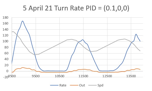
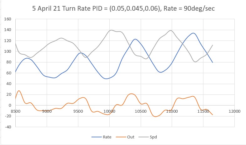
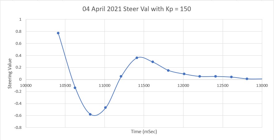
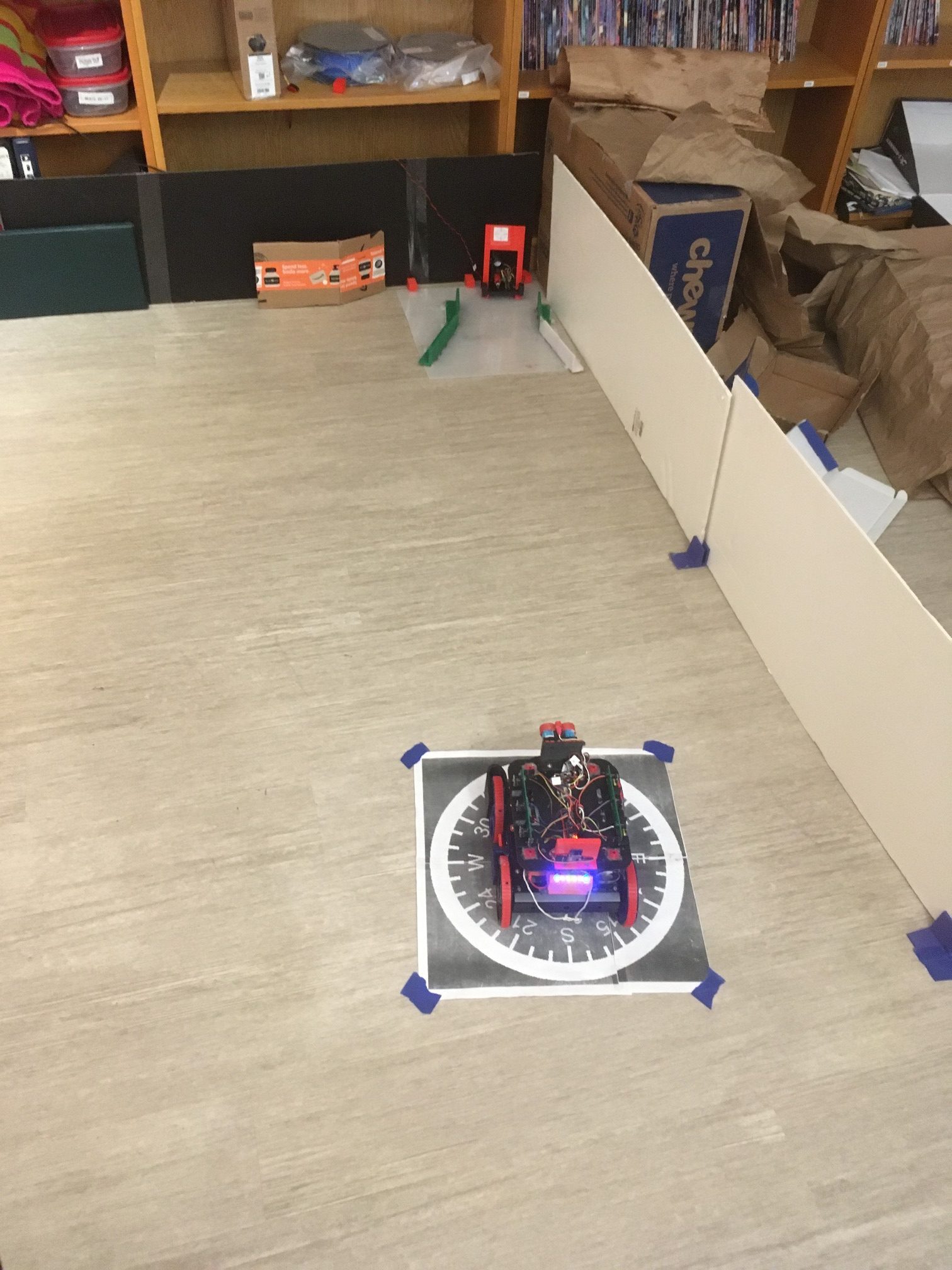
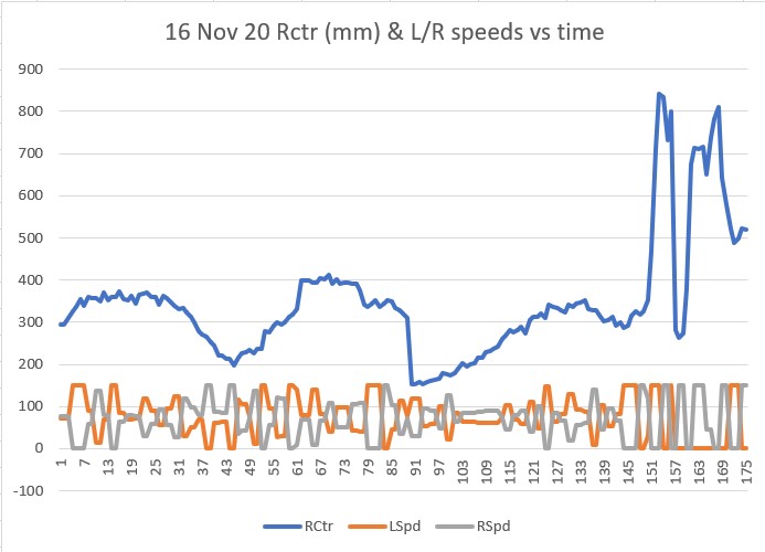
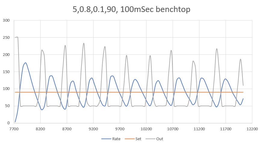
After a number of trials, I started getting some reasonable results on my benchtop (hard surface with a thin electrostatic mat), as shown below:
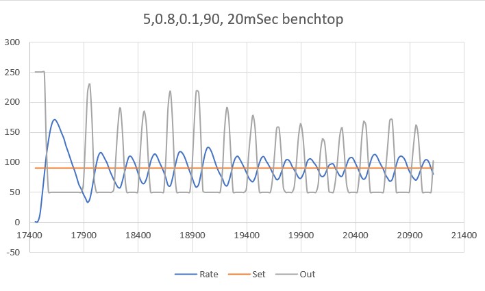
As can be seen in the above plot, the turn rate is controlled pretty well around the 90 deg/sec turn rate, with an average turn rate of 89.6 deg/sec.
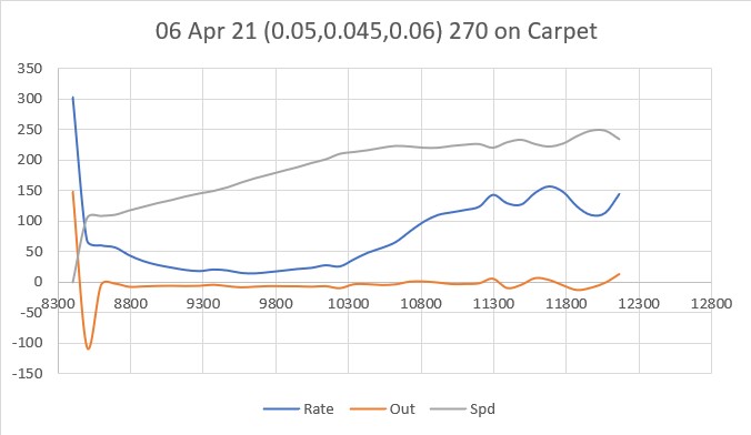
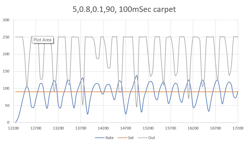
The plot below shows the same parameter set, but run on carpet rather than my bench.
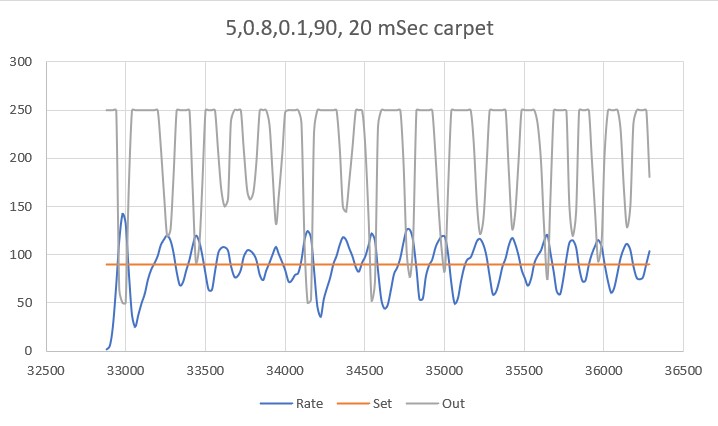
Comparing these two plots it is obvious that a lot more motor current is required to make the robot turn on carpet, due to the much higher sideways friction on the wheels.
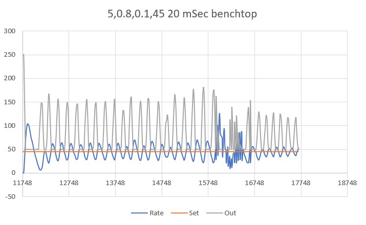
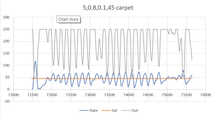
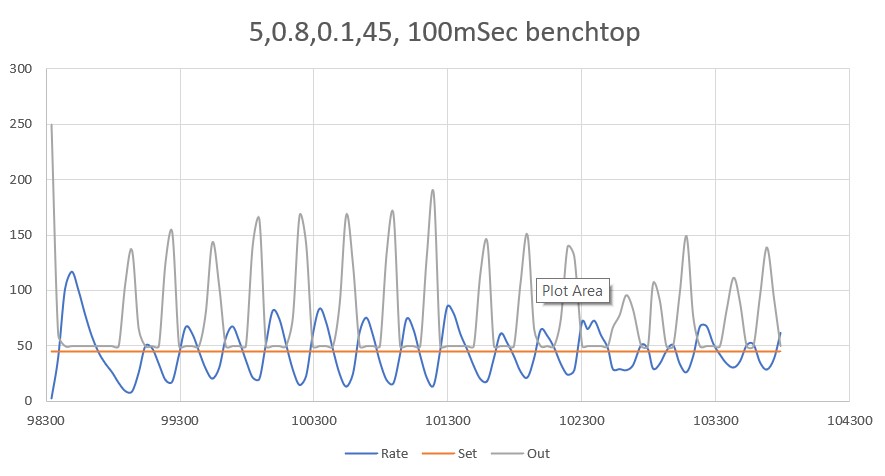
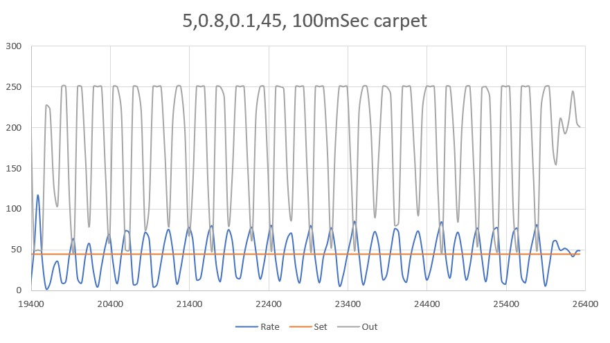
The next step was to see if the PID parameters for 90 deg/sec would also handle different turn rates. Here are the plots for 45 deg/sec on my benchtop and on carpet:
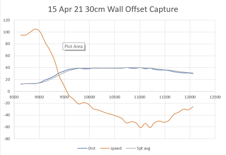
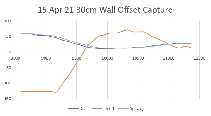
And then 30 deg/sec on benchtop and carpet
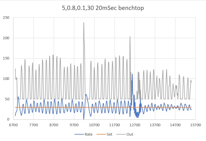
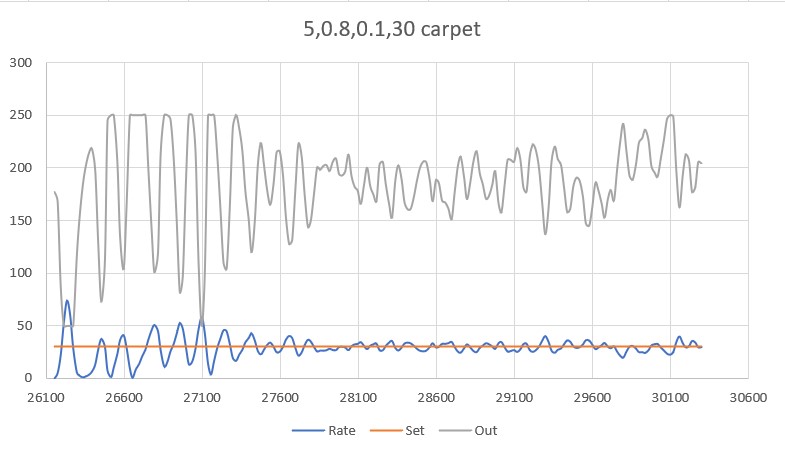
It is clear from the above plots that the PID values (5,0.8,0.1) do fairly well for the four wheel robot, both on hard surfaces and carpet.
Having this kind of control over turn rate is pretty nice. I might even be able to do turns by setting the turn rate appropriately and just timing the turn, or even vary the turn rate during the turn. For a long turn (say 180 deg) I could do the first 90-120 at 90 deg/sec, and then do the last 90-60 at 30 deg/sec; might make for a much more precise turn.
All of the above tests were done with a 20 mSec time interval, which is 5x smaller than the current 100mSec time interval used for the master timer in Wall-E2. So, my next set of tests will keep the turn rate constant and slowly increase the time interval to see if I can get back to 100 mSec without any major sacrifice in performance.
28 May 2021 Update:
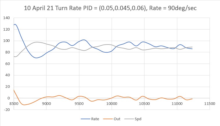
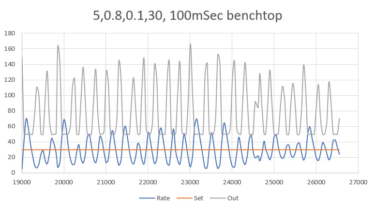
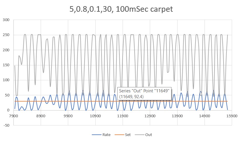
I went back through the tests using a 100 mSec interval instead of 20 mSec, and was gratified to see that there was very little degradation in performance. The turn performance was a bit more ‘jerky’ than with a 20 mSec interval, but still quite acceptable, and very well controlled, both on the benchtop and carpet surfaces – Yay! Here are some plots to show the performance.
31 May 2021 Update:
I made some additional runs on benchtop and carpet, thinking I might be able to reduce the turn-rate oscillations a bit. I found that by reducing the time interval back to 20 mSec and increase the ‘D’ (differential) parameter. After some tweaking back and forth, I wound up with a PID set of (5, 0.8, 3). Using these parameters, I got the following performance plots.
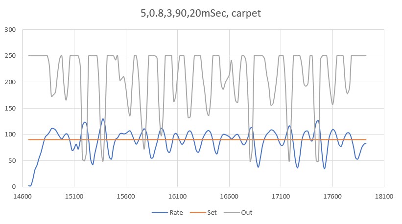
As can be seen in the Excel plot and the movie, the turn performance is much smoother – yay!
Stay tuned!
Frank