/*
Name: FourWD_WallE2_V7.ino
Created: 9/24/2020 11:03:59 AM
Author: FRANKNEWXPS15\Frank
*/
#define TIMER_INT_OUTPUT_PIN 51 //scope monitor pin
#pragma region INCLUDES
#include <avr/sleep.h> //needed for sleep_enable() & sleep_cpu() functions
#include <elapsedMillis.h>
#include <PrintEx.h> //allows printf-style printout syntax
#include "MPU6050_6Axis_MotionApps_V6_12.h" //changed to this version 10/05/19
#include "I2Cdev.h" //02/19/19: this includes SBWire.h
#include "I2C_Anything.h" //needed for sending float data over I2C
#include "Adafruit_FRAM_I2C.h"
#include "RTClib.h" //07/11/20 this MUST be the #include "file" form for the "Local files override.." option to work
#include <PID.h> //moved here 02/09/19
#include <limits.h> //added 04/19/19
#pragma endregion Includes
#pragma region DEFINES
//02/29/16 hardware defines
//#define NO_MOTORS
//#define NO_LIDAR
//#define NO_PINGS
//#define NO_IRDET //added 04/05/17 for daytime in-atrium testing (too much ambient IR)
//#define DISTANCES_ONLY //added 11/14/18 to just display distances in infinite loop
#define NO_FRAM_TELEMETRY //added 11/14/18
//#define FORCE_RTC_TO_LAST_COMPILE_TIME //added 02/18/19. Forces RTC to last compile time
#define NO_STUCK //added 03/10/19 to disable 'stuck' detection
//#define BATTERY_DISCHARGE //added 03/04/20 to discharge battery safely
#define NO_POST //added 04/12/20 to skip all the POST checks
#pragma endregion Program #Defines
#pragma region PRE_SETUP
StreamEx mySerial = Serial; //added 03/18/18 for printf-style printing
Adafruit_FRAM_I2C fram = Adafruit_FRAM_I2C(); //I2C addr = 0x50 (default)
//FramPacket.h holds 'inline' definition of CFRAMStatePacket class
/*this has to come after the following lines
#include "Adafruit_FRAM_I2C.h"
Adafruit_FRAM_I2C fram = Adafruit_FRAM_I2C();
StreamEx mySerial = Serial; //added 03/18/18 for printf-style printing
*/
#include "FramPacket.h"
//tri-sensor board
RTC_DS3231 rtc; //I2C addr = 0x68
MPU6050 mpu(0x69); //06/23/18 chg to AD0 high addr, using INT connected to Mega pin 2 (INT0)
CFRAMStatePacket FramPacket = CFRAMStatePacket(&fram); //this object is used for all FRAM transactions
const char daysOfTheWeek[7][12] = { "Sunday", "Monday", "Tuesday", "Wednesday", "Thursday", "Friday", "Saturday" };//used for RTC date/time readouts
//added 01/30/17 for IR homing support
#pragma region IRHOMING
uint8_t IR_HOMING_MODULE_SLAVE_ADDR = 8; //uint8_t type reqd here for Wire.requestFrom() call
double IRHomingSetpoint, IRHomingLRSteeringVal, IRHomingOutput;//10/06/17 chg input variable name to something more descriptive
PID IRHomingPID(&IRHomingLRSteeringVal, &IRHomingOutput, &IRHomingSetpoint, 1000, 0.0, 200.0, REVERSE);//10/15/17 'final' setup
const long IR_BEAM_DETECTION_CHANNEL_MAX = 2621440;
const long IR_BEAM_DETECTION_THRESHOLD = 10000;
#pragma endregion IR Homing Parameters
#pragma region ENUMS
//01/05/16 enum types cannot be used as arguments or return types for functions due to Arduino pre-processor quirk
//12/20/15 added for navigation support
//01/15/16 revised to be consistent wtih nav modes identified in https://fpaynter.com/2016/01/making-wall-e2-smarter-using-karnaugh-maps/
enum NavCases
{
NAV_NONE = 0,
NAV_WALLTRK,
NAV_OBSTACLE,
NAV_STEPTURN,
NAV_STUCK,
NAV_OPENCNR
};
//04/10/20 Experiment with porting heading based tracking capability from two wheel robot
enum TrackingState
{
TRK_RIGHT_NONE,
TRK_RIGHT_CAPTURE,
TRK_RIGHT_MAINTAIN,
TRK_RIGHT_BACKUP_AND_TURN,
TRK_RIGHT_STEP_TURN
};
const char* NavStrArray[] = { "WallTrack", "Obstacle", "StepTurn", "Stuck", "OpenCorner" };
//03/08/17 added for new mode/state definitions; see https://fpaynter.com/2017/03/wall-e2-operating-mode-review/
enum OpModes
{
MODE_NONE = 0, //04/04/17 chg from MODE_DEFAULT and moved to top (zero) position
MODE_CHARGING,
MODE_IRHOMING,
MODE_WALLFOLLOW,
MODE_DEADBATTERY, //added 01/16/18 to handle dead battery case
MODE_DISCHARGE //added 03/04/20 to safely discharge the battery
};
const char* ModeStrArray[] = { "None", "Charge", "Home", "Wall", "DeadBatt", "Discharge" };
const char* LongModeStrArray[] = { "None", "Charging", "IR Homing", "Wall Following", "Dead Battery", "Discharging" };
enum WallTrackingCases
{
TRACKING_NONE = 0,
TRACKING_LEFT,
TRACKING_RIGHT,
TRACKING_NEITHER
};
const char* TrkStrArray[] = { "None", "Left", "Right", "Neither" };
#pragma endregion Tracking and Nav Case Enums
#pragma region BATTCONSTS
//03/10/15 added for battery charge level monitoring
//const int LOW_BATT_THRESH_VOLTS = 7.4; //50% chg per http://batteryuniversity.com/learn/article/lithium_based_batteries
const int LOW_BATT_THRESH_VOLTS = 8.4; //07/10/20 temp debug settingr//50% chg per http://batteryuniversity.com/learn/article/lithium_based_batteries
const int MAX_AD_VALUE = 1023;
const long BATT_CHG_TIMEOUT_SEC = 36000; //10 HRS, for test only
//const long BATT_CHG_TIMEOUT_MIN = 120; //2 hours. Chg to min vs sec 01/09/18
const float DEAD_BATT_THRESH_VOLTS = 6; //added 01/24/17
//const float DEAD_BATT_THRESH_VOLTS = 6.2; //chg to 6.2 03/02/19 per https://www.fpaynter.com/2019/03/better-battery-charging-for-wall-e2/
//const float FULL_BATT_VOLTS = 8.2; //added 03/17/18. Chg to 8.2 02/24/19
const float FULL_BATT_VOLTS = 8.4; //added 03/17/18. Chg to 8.4 03/05/20
const int MINIMUM_CHARGE_TIME_SEC = 10; //added 04/01/18
const float VOLTAGE_TO_CURRENT_RATIO = 0.75f; //Volts/Amp rev 03/01/19. Used for both 'Total' and 'Run' sensors
const float FULL_BATT_CURRENT_THRESHOLD = 0.5; //amps chg to 0.5A 03/02/19 per https://www.fpaynter.com/2019/03/better-battery-charging-for-wall-e2/
const int CURRENT_AVERAGE_NUMBER = 10; //added 03/01/19
const int VOLTS_AVERAGE_NUMBER = 5; //added 03/01/19
const int IR_HOMING_TELEMETRY_SPACING_MSEC = 200; //added 04/23/20
//battery fuel guage constants
const float _20PCT_BATT_VOLTS = DEAD_BATT_THRESH_VOLTS + 0.2f * (FULL_BATT_VOLTS - DEAD_BATT_THRESH_VOLTS);
const float _40PCT_BATT_VOLTS = DEAD_BATT_THRESH_VOLTS + 0.4f * (FULL_BATT_VOLTS - DEAD_BATT_THRESH_VOLTS);
const float _60PCT_BATT_VOLTS = DEAD_BATT_THRESH_VOLTS + 0.6f * (FULL_BATT_VOLTS - DEAD_BATT_THRESH_VOLTS);
const float _80PCT_BATT_VOLTS = DEAD_BATT_THRESH_VOLTS + 0.8f * (FULL_BATT_VOLTS - DEAD_BATT_THRESH_VOLTS);
const float ZENER_VOLTAGE_OFFSET = 5.84; //measured zener voltage
const float ADC_REF_VOLTS = 3.3; //03/27/18 now using analogReference(EXTERNAL) with Teensy 3.3V connected to AREF
#pragma endregion Battery Constants
#pragma region DISTANCE_MEASUREMENT_SUPPORT
//misc LIDAR and Ping sensor parameters
const int MIN_OBS_DIST_CM = 20; //rev 04/28/17 for better obstacle handling
const int CHG_STN_AVOIDANCE_DIST_CM = 30; //added 03/11/17 for charge stn avoidance
//const int STEPTURN_DIST_CM = 80; //rev 04/28/17 to be indep of MIN_OBS_DIST_CM
//const int STEPTURN_DIST_CM = 0; //rev 05/16/20 to temporarily disable
const int STEPTURN_DIST_CM = 50; //rev 06/29/20 to temporarily disable
const int MAX_FRONT_DISTANCE_CM = 400;
const int MAX_LR_DISTANCE_CM = 200; //04/19/15 now using sep parameters for front and side sensors
//const int MIN_PING_INTERVAL_MSEC = 200; //rev 03/12/16
//const int MIN_PING_INTERVAL_MSEC = 50; //rev 10/03/20
const int MIN_PING_INTERVAL_MSEC = 30; //rev 10/03/20
const int CHG_STN_FINAL_APPR_DIST_CM = 20; //added 03/11/17 for charge stn avoidance
//04/01/2015 added for 'stuck' detection support
const int FRONT_DIST_ARRAY_SIZE = 25; //04/28/19 - final value (I hope)
const int FRONT_DIST_AVG_WINDOW_SIZE = 3; //moved here & renamed 04/28/19
const int LR_PING_DIST_ARRAY_SIZE = 3; //04/28/19 added to reinstate l/r dist running avg
const int LR_PING_AVG_WINDOW_SIZE = 3; //added 04/28/19 so front & lr averages can differ
const int STUCK_FRONT_VARIANCE_THRESHOLD = 50; //chg to 50 04/28/17
//const int STUCK_FRONT_VARIANCE_THRESHOLD = 0; //chg to 0 09/15/18
const int NO_LIDAR_FRONT_VAR_VAL = 10 * STUCK_FRONT_VARIANCE_THRESHOLD; //01/16/19
uint16_t aFrontDist[FRONT_DIST_ARRAY_SIZE]; //04/18/19 rev to use uint16_t vs byte
//04/28/19 added to reinstate l/r dist running avg
//06/28/20 chg to uint_16 to accommodate change from cm to mm
//byte aLeftDist[LR_PING_DIST_ARRAY_SIZE];
//byte aRightDist[LR_PING_DIST_ARRAY_SIZE];
uint16_t aLeftDist[LR_PING_DIST_ARRAY_SIZE];
uint16_t aRightDist[LR_PING_DIST_ARRAY_SIZE];
//added 12/26/14 for wall following support
int prevleftdistval = 0;
int prevrightdistval = 0;
int prevfrontdistcm = 0;
int curMinObstacleDistance = MIN_OBS_DIST_CM;//added 03/11/17 for chg stn avoidance
//04/13/20 moved distance vars up here so can be initialized just before loop()
int leftdistval = 0;
int rightdistval = 0;
int frontdistval = 0;
//double frontvar = 0;
volatile double frontvar = 0; //08/11/20 now updated in timer1 ISR
#pragma endregion Distance Measurement Support
#pragma region MOTOR_PARAMETERS
//drive wheel speed parameters
const int MOTOR_SPEED_FULL = 200; //range is 0-255
const int MOTOR_SPEED_MAX = 255; //range is 0-255
const int MOTOR_SPEED_HALF = 127; //range is 0-255
const int MOTOR_SPEED_QTR = 75; //added 09/25/20
const int MOTOR_SPEED_LOW = 50; //added 01/22/15
const int MOTOR_SPEED_OFF = 0; //range is 0-255
const int MOTOR_SPEED_CAPTURE_OFFSET = 75; //added 06/21/20 for offset capture
//const int MOTOR_SPEED_CAPTURE_OFFSET = 125; //added 06/28/20 for offset capture
const int MOTOR_SPEED_ADJ_FACTOR = 40; //chg to 40 at 5:55pm
const int LEFT_SPEED_COMP_VAL_FWD = 15; //left speed compensation value
const int RIGHT_SPEED_COMP_VAL_FWD = -LEFT_SPEED_COMP_VAL_FWD; //right speed compensation value
const int LEFT_SPEED_COMP_VAL_REV = 5; //left speed compensation value
const int RIGHT_SPEED_COMP_VAL_REV = -LEFT_SPEED_COMP_VAL_REV; //right speed compensation value
//drive wheel direction constants
const boolean FWD_DIR = true;
const boolean REV_DIR = !FWD_DIR;
//Motor direction variables
boolean bLeftMotorDirIsFwd = true;
boolean bRightMotorDirIsFwd = true;
bool bIsForwardDir = true; //default is foward direction
#pragma endregion Motor Parameters
#pragma region HEADING_BASED_TURN_PARAMS
//09/11/18 new heading-based turn support constants
const int ESS_TURN_DEG = 45;
const int QUARTER_TURN_DEG = 90;
const float DEFAULT_HDG_JUMP_VAL = 20.f;
const int DEFAULT_TURN_DEG = QUARTER_TURN_DEG;
const float ROLLING_TURN_MAX_SEC_PER_DEG = 1 / 15.0; //used to limit time in rolling turns
//const int OFFSIDE_MOTOR_SPEED = MOTOR_SPEED_LOW;
//const int OFFSIDE_MOTOR_SPEED = 0; //03/04/20 debug
const int OFFSIDE_MOTOR_SPEED = 25; //03/04/20 turn debug - leave at this value for now
const int DRIVESIDE_MOTOR_SPEED_HIGH = MOTOR_SPEED_MAX;
const int DRIVESIDE_MOTOR_SPEED_HALF = MOTOR_SPEED_HALF;//added 02/16/20 for wall tracking support
const int DRIVESIDE_MOTOR_SPEED_LOW = MOTOR_SPEED_HALF;
const long MSEC_PER_HDG_CHECK = 100; //added 08/29/18
const float HDG_NEAR_MATCH_VAL = 0.9; //slow the turn down here
//const float HDG_FULL_MATCH_VAL = 0.98; //stop the turn here
const float HDG_FULL_MATCH_VAL = 0.99; //stop the turn here //rev 05/17/20
const float HDG_MIN_MATCH_VAL = 0.6; //added 09/08/18: don't start checking slope until turn is well started
elapsedMillis sinceLastTimeCheck; //used for rolling turn timeout
#pragma endregion Heading-based turn support parameters
#pragma region VL53L0X_TOF_LIDAR_SUPPORT
//const int ToFArray_PARALLEL_FIND_Kp = 800;
//const int ToFArray_PARALLEL_FIND_Kp = 80;
//const int ToFArray_PARALLEL_FIND_Kp = 120;
const int ToFArray_PARALLEL_FIND_Kp = 200;
const int ToFArray_PARALLEL_FIND_Ki = 20; //added 09/22/20
const int ToFArray_PARALLEL_FIND_Kd = 0; //added 09/22/20
//const float ToFArray_PARALLEL_FIND_SETPOINT = 0.05; //09/22/20 moved here
const float ToFArray_PARALLEL_FIND_SETPOINT = 0.01; //09/22/20 moved here
const int ToFArray_OFFSET_CAPTURE_Kp = 200;
//const int ToFArray_OFFSET_CAPTURE_Ki = 0; //06/28/20
const int ToFArray_OFFSET_CAPTURE_Ki = 50;
const int ToFArray_OFFSET_CAPTURE_Kd = 50;
const int ToFArray_OFFSET_TRACK_Kp = 10;
const int ToFArray_OFFSET_TRACK_Kd = 0;
//const int ToFArray_OFFSET_TRACK_Kd = 50;
double LeftSteeringVal, RightSteeringVal; //added 08/06/20
double ToFSetpoint, ToFSteeringVal, ToFOutput;//10/06/17 chg input variable name to something more descriptive
PID ToFArrayPID(&ToFSteeringVal, &ToFOutput, &ToFSetpoint, ToFArray_PARALLEL_FIND_Kp, 0.0, 0.0, DIRECT);//06/19/20 use this for now
const int ROTATE_TO_PARALLEL_TELEMETRY_SPACING_MSEC = 200;
const float PARALLEL_ORIENTATION_STEERING_VALUE_THRESHOLD = 0.1; //rev 06/21/20 - now using (F-R)/100
//const float CAPTURE_APPROACH_STEERING_VALUE = 0.2; //added 06/21/20 - now using (F-R)/100
const float CAPTURE_APPROACH_STEERING_VALUE = 0.4; //rev 06/28/20 - now using (F-R)/100
//const float WALL_OFFSET_CAPTURE_WINDOW_CM = 5.0; //just a guess
const float WALL_OFFSET_CAPTURE_WINDOW_CM = 2.0; //just a guess
const int VL53L0X_I2C_SLAVE_ADDRESS = 0x20; ////Teensy 3.5 VL53L0X ToF LIDAR controller
//Sensor data values
int Lidar_RightFront;
int Lidar_RightCenter;
int Lidar_RightRear;
int Lidar_LeftFront;
int Lidar_LeftCenter;
int Lidar_LeftRear;
elapsedMillis lastToFArrayTelemetryMsec; //used to space out telemetry prints
enum VL53L0X_REQUEST
{
VL53L0X_CENTERS_ONLY,
VL53L0X_RIGHT,
VL53L0X_LEFT,
VL53L0X_BOTH //added 08/06/20
};
#pragma endregion VL53L0X ToF LIDAR Support
//vvvvvvvvvvvvvvvvvvvvvvvvvvvvvvvvvvvvvvvvvvvvvvvvvvvvvvvvvvvvvv//
//=================== START PIN ASSIGNMENTS ===================//
//vvvvvvvvvvvvvvvvvvvvvvvvvvvvvvvvvvvvvvvvvvvvvvvvvvvvvvvvvvvvvv//
#pragma region MOTOR_PINS
//09/11/20 Now using two Adafruit DRV8871 drivers for all 4 motors
const int In1_Left = 10;
const int In2_Left = 11;
const int In1_Right = 8;
const int In2_Right = 9;
#pragma endregion Motor Pin Assignments
//Laser pointer
const int RED_LASER_DIODE_PIN = 7;
//LIDAR MODE pin (continuous mode)
const int LIDAR_MODE_PIN = 4; //mvd here 01/10/18
//BATT Monitor and IR Detector pin assignments added 01/30/17
const int BATT_MON_PIN = A1;
#pragma region CHG_SUPP_PINS
//04/22/20 bugfix - RUN & TOT input definitions were reversed
//const int RUN_CURR_PIN = A8; //02/25/19 bugfix 02/28/19 name chg
//const int TOT_CURR_PIN = A9; //02/24/19 now connected to 1NA619 charge current sensor
const int RUN_CURR_PIN = A9; //connected to 1NA619 between battery and rest of robot
const int TOT_CURR_PIN = A8; //connected to 1NA619 between charge plug and battery
const int CHG_CONNECT_PIN = 23; //goes HIGH when chg cable connected
//LED en/dis output pins
//03/15/18 revised for TP5100 module
const int FIN_LED_PIN = 35;
const int _80PCT_LED_PIN = 33;
const int _60PCT_LED_PIN = 31;
const int _40PCT_LED_PIN = 29;
const int _20PCT_LED_PIN = 27;
const int CHG_LED_PIN = 25; //pwr2 signal line repl by Batt2
long chgStartMsec;//added 02/24/17
#pragma endregion Charge Control/Status Pins
//05/03/17 moved below Chg supp LED defs so can re-use them
//03/15/18 revised for TP5100 module
#pragma region BACKUP_TURN_LED_PINS
//03/19/18 new plan - use 'full/half/qtr_left, full/half/qtr_right aliases
const int FULL_LEFT_LED_PIN = FIN_LED_PIN;
const int HALF_LEFT_LED_PIN = _80PCT_LED_PIN;
const int QTR_LEFT_LED_PIN = _60PCT_LED_PIN;
const int QTR_RIGHT_LED_PIN = _40PCT_LED_PIN;
const int HALF_RIGHT_LED_PIN = _20PCT_LED_PIN;
const int FULL_RIGHT_LED_PIN = CHG_LED_PIN;
#pragma endregion Rear Bumper Display LEDs
#pragma region SPEAKER_CONSTANTS
//const int SOS_PWM_PIN = 3;
const int SOS_PWM_PIN = 2; //chg to proper pin 09/13/2020
const int DOT_MS = 200;
const int DASH_MS = 800;
const int HIGHTONE = 1000;
const int LOWTONE = 500;
#pragma endregion Speaker Constants
//const int PWRDWN_INTERRUPT_PIN = 2; //added 03/27/18
//^^^^^^^^^^^^^^^^^^^^^^^^^^^^^^^^^^^^^^^^^^^^^^^^^^^^^^^^//
//=================== END PIN ASSIGNMENTS ================//
//^^^^^^^^^^^^^^^^^^^^^^^^^^^^^^^^^^^^^^^^^^^^^^^^^^^^^^^^//
//03/08/17 added Mode/state-specific telemetry header strings
#pragma region TELEMETRYSTRINGS
//const String IRHomingTelemStr = "Time\tBattV\tFin1\tFin2\tSteer\tPID_In\tPID_Out\tLSpd\tRSpd";
const String IRHomingTelemStr = "Time\tBattV\tFin1\tFin2\tSteer\tPID_Out\t\tLSpd\tRSpd\tFrontD";
//const String WallFollowTelemStr = "DateTime\tBatt\tMode\tTrack\tLeft\tRight\tFront\tVar\tLSpd\tRSpd";
//const char* WallFollowTelemStr = "DateTime\tBatt\tMode\tTrack\tLeft\tRight\tFront\tVar\tLSpd\tRSpd";
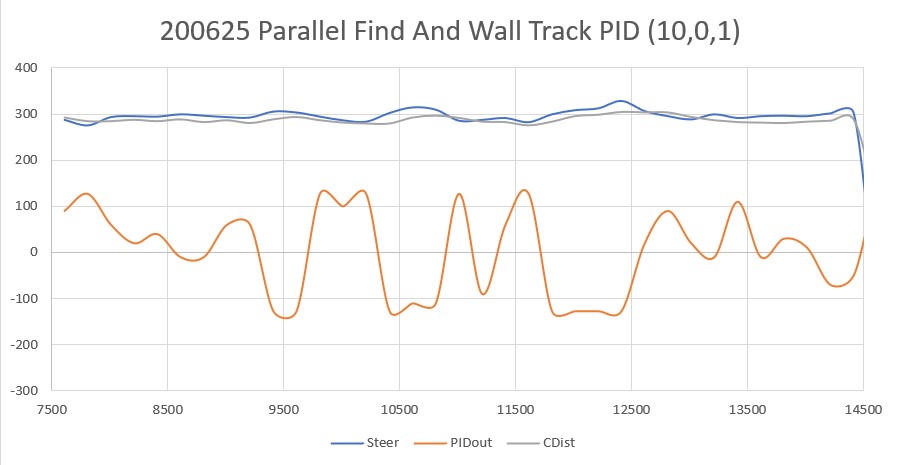
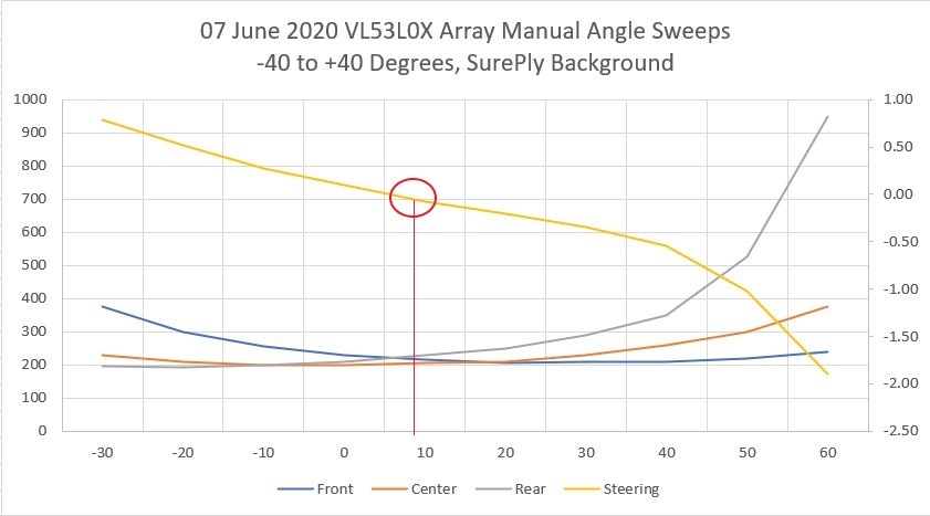
const char* WallFollowTelemStr = "Msec\tMode\tTrack\tFront\tCtr\tRear\tSteer\tOutput\tLSpd\tRSpd"; //09/01/20 PID tuning
//const String WallFollowTelemStr = "NewDist\tOldDist\tBmean\tBvar\tOldImean\tOldIvar\tOldD^2\tNewD^2\tImean\tIvar"; //04/17/19 added for Ivar debug
//const String WallFollowTelemStr = "New_D\tOld_D\tB_mean\tB_var\told_Im\told_Ivar\told_d^2\tnew_d^2\tI_mean\tIm_sq\toldIm_sq\tI_var\tB_uSec\tI_uSec\n";
//const String ChargingTelemStr = "ChgSec\tBattV\tTotalI\tRunI\tChgI\tATotI\tARunI\tChrging\n"; //rev 02/28/19 to chg 'BattI' to 'TotI', added 'RunI', ChgI
const String ChargingTelemStr = "ChgSec\tBattV\tTotalI\tRunI\tChgI\n"; //rev 05/02/20
#pragma endregion Mode-specific telemetry header strings
#pragma region LOOP_VARS
//loop() variables
double deltaD = 0;
double olddist = 0;
double newdist = 0;
boolean bStuck = false;
int leftspeednum = MOTOR_SPEED_HALF;
int rightspeednum = MOTOR_SPEED_HALF;
elapsedMillis sinceLastNavUpdateMsec; //added 10/15/18 to replace lastmillisec
NavCases NavCase = NAV_WALLTRK;
WallTrackingCases TrackingCase = TRACKING_NEITHER; //added 01/05/16
WallTrackingCases PrevTrackingCase = TRACKING_LEFT;
OpModes PrevOpMode = MODE_NONE; //added 03/08/17, rev to MODE_NONE 04/04/17
OpModes CurrentOpMode = MODE_NONE; //added 10/13/17 so can use in motor speed setting routines
//04/10/20 added for experiment to port heading based wall tracking from two wheel robot
TrackingState CurrentTrackingState = TRK_RIGHT_NONE;
TrackingState PrevTrackingState = TRK_RIGHT_NONE;
//02/13/16 added for 'pause' debug
int m_FinalLeftSpeed = 0;
int m_FinalRightSpeed = 0;
//11/03/18 added for new incremental variance calc
double last_incvar = 0;
double last_incmean = 0;
elapsedMillis lastHomingTelemetryMsec; //used to space out telemetry prints
#pragma endregion Loop Variables
#pragma region I2C_VARS
#pragma endregion I2C related parameters
#pragma region TRISENSOR PARAMS
//FRAM constants/params
const int NUM_FRAM_BYTES_TO_CLEAR = 2000;
const int FIRST_TIME_STORAGE_ADDR = 2;//addr 0/1 reserved for nextFramWriteAddr
const int NEXTFRAMWRITEADDR_FRAMSTORAGELOCATION = 0;
const int NUM_TIMES_TO_DISPLAY = 10;
//const unsigned long FRAM_WRITE_INTERVAL_MSEC = 60000; //one minute
const unsigned long FRAM_WRITE_INTERVAL_MSEC = 6000; //one minute
int nextFramWriteAddr = FIRST_TIME_STORAGE_ADDR;
elapsedMillis sinceLastFRAMWriteMsec; //added 09/19/18
#pragma endregion TRISENSOR
#pragma region MPU6050_SUPPORT
uint8_t mpuIntStatus; // holds actual interrupt status byte from MPU. Used in Homer's Overflow routine
uint8_t devStatus; // return status after each device operation (0 = success, !0 = error)
uint16_t packetSize; // expected DMP packet size (default is 42 bytes)
uint16_t fifoCount; // count of all bytes currently in FIFO
uint8_t fifoBuffer[64]; // FIFO storage buffer
// orientation/motion vars
Quaternion q; // [w, x, y, z] quaternion container
VectorInt16 aa; // [x, y, z] accel sensor measurements
VectorInt16 aaReal; // [x, y, z] gravity-free accel sensor measurements
VectorInt16 aaWorld; // [x, y, z] world-frame accel sensor measurements
VectorFloat gravity; // [x, y, z] gravity vector
float euler[3]; // [psi, theta, phi] Euler angle container
float ypr[3]; // [yaw, pitch, roll] yaw/pitch/roll container and gravity vector
int GetPacketLoopCount = 0;
int OuterGetPacketLoopCount = 0;
//MPU6050 status flags
bool bMPU6050Ready = true;
bool dmpReady = false; // set true if DMP init was successful
volatile float IMUHdgValDeg = 0; //updated by UpdateIMUHdgValDeg()
const uint16_t MAX_GETPACKET_LOOPS = 100; //10/30/19 added for backup loop exit condition in GetCurrentFIFOPacket()
uint8_t GetCurrentFIFOPacket(uint8_t* data, uint8_t length, uint16_t max_loops = MAX_GETPACKET_LOOPS); //prototype here so can define a default param
bool bFirstTime = true;
#define MPU6050_CCW_INCREASES_YAWVAL //added 12/05/19
#pragma endregion MPU6050 Support
#pragma region FRAM/RTC Support
//RTC/FRAM/MPU6050 status flags
bool RTC_Avail = true;
bool bRTCLostPower = false; //added 10/17/18
bool bFRAMReady = true;
#pragma endregion FRAM/RTC Support
#pragma region WALL_FOLLOW_SUPPORT
//12/05/19 defiine 'TURNDIR_CCW' & 'TURN_CW' identifiers for better readability. Now I can call
//RollingTurn(TURNDIR_CCW,...) and RollingTurn(TURNDIR_CW) instead of just RollingTurn(true/false)
const bool TURNDIR_CCW = true;
const bool TURNDIR_CW = false;
const int DESIRED_WALL_OFFSET_DIST_CM = 30;
const int ROLLING_TURN_RADIUS_CM = 5;
//const int NINETY_DEG_FUDGE_FACTOR_CM = 5; //added 04/17/20
const int NINETY_DEG_FUDGE_FACTOR_CM = 10; //added 04/17/20
const int WALL_APPR_ERR_WIN_MULTFACT = 2; //added 08/12/19
const int WALL_APPR_MAX_AGGREGATE_CUT = 30; //added 05/09/20
const int WALL_TRK_ERR_WIN_MULTFACT = 1; //added 08/12/19
const int VERY_FAR_AWAY_CM = 5;
const int FAR_AWAY_CM = 2;
const int CLOSE_CM = 1;
const int VERY_FAR_AWAY_TURN_DEG = 20;
const int FAR_AWAY_TURN_DEG = 10;
const int CLOSE_TURN_DEG = 5;
const int TURN_INCREMENT_DEG = 10;
int m_PrevHdgCutDeg = 0;
bool m_PrevHdgCutDir = TURNDIR_CW; //CW
int m_PrevLeftDistCm = 0;
int m_PrevRightDistCm = 0;
int m_AggregateCutDeg = 0; //added 05/09/20
elapsedMillis sinceLastHdgCutUpdateMsec; //added 10/15/18 to replace lastmillisec
int m_TrkErrWinMult = WALL_APPR_ERR_WIN_MULTFACT; //used to increase close in response
bool bIsFirst180 = true; //added 01/25/20 for boomerang mode tracking
elapsedMillis mSecSinceLastParDistChk = 0; //added 02/14/20 to steepen distance/measurement slope
#pragma endregion Wall Following Support
#pragma endregion PRE_SETUP
#pragma region TIMER_ISR
//08/10/20 added timer ISR
volatile bool bIsStuck = false;
volatile bool bIsStuck_Slow = false; //08/12/20 added for half-speed offset capture operations
volatile bool bObstacleAhead = false;
volatile uint32_t Last_ISR_Msec;
volatile bool bTimeForNavUpdate = false;
//DEBUG!!
//uint32_t elapsedUsec = micros()-Last_ISR_Msec;
//mySerial.printf("MSec\tUSec\tFdist\tFvar\n");
//mySerial.printf("%lu\t%lu\t%d\t%2.3f\n", millis(), elaspsed, frontdist, frontvar);
//DEBUG!!
//
ISR(TIMER5_COMPA_vect) //timer1 interrupt 1Hz toggles pin 13 (LED)
{
//digitalWrite(TIMER_INT_OUTPUT_PIN, HIGH);
//delayMicroseconds(30);
//digitalWrite(TIMER_INT_OUTPUT_PIN, LOW);
bTimeForNavUpdate = true;
#ifndef NO_STUCK
uint16_t frontdist = GetFrontDistCm();
frontvar = CalcDistArrayVariance(frontdist, aFrontDist);
bIsStuck = frontvar < STUCK_FRONT_VARIANCE_THRESHOLD;
bIsStuck_Slow = frontvar < STUCK_FRONT_VARIANCE_THRESHOLD / 2;
bObstacleAhead = frontdist < MIN_OBS_DIST_CM;
#endif // !NO_STUCK
}
#pragma endregion TIMER_ISR
#pragma region WALL_OFFSET_TRACKING
const int WALL_OFFSET_TRACK_Kp = 100;
const int WALL_OFFSET_TRACK_Ki = 0;
const int WALL_OFFSET_TRACK_Kd = 0;
const double WALL_OFFSET_TRACK_SETPOINT_LIMIT = 0.3;
double WallTrackSteerVal, WallTrackOutput, WallTrackSetPoint;
PID WallTrackPID(&WallTrackSteerVal, &WallTrackOutput, &WallTrackSetPoint, WALL_OFFSET_TRACK_Kp, 0.0, 0.0, REVERSE);
#pragma endregion Wall Offset Tracking Support
#pragma region SETUP
void setup()
{
Serial.begin(115200);
delay(1000);
FramPacket = CFRAMStatePacket(&fram); //09/27/18 comes after Serial.begin(). Calls Wire.begin() & fram.begin()
#pragma region RTC
if (rtc.begin()) //02/19/19 this now returns FALSE if RTC doesn't respond
{
Serial.println("Found RTC...");
delay(100);
bRTCLostPower = rtc.lostPower(); //added 10/17/18
mySerial.printf("rtc.lostPower() reports %d\n", bRTCLostPower);
if (rtc.lostPower())
{
Serial.println("RTC lost power. Setting RTC to last compile time");
rtc.adjust(DateTime(F(__DATE__), F(__TIME__)));// sets RTC to last compile date/time
}
#ifdef FORCE_RTC_TO_LAST_COMPILE_TIME
Serial.println("Forcing RTC to last compile time");
rtc.adjust(DateTime(F(__DATE__), F(__TIME__)));// sets RTC to last compile date/time
#endif
DateTime now = rtc.now();
char buffer[100];
memset(buffer, '\0', 100);
mySerial.printf("Retrieving Date/Time from RTC with rtc.now() = %ld\n", now.unixtime());
GetDayDateTimeStringFromDateTime(now, buffer);
Serial.print("Date/Time: "); Serial.println(buffer);
RTC_Avail = true;
}
else
{
Serial.println("Couldn't find RTC. Real-time clock functions won't be available");
RTC_Avail = false; //use this instead
}
if (RTC_Avail && rtc.lostPower())
{
DateTime Comp_dt = DateTime(F(__DATE__), F(__TIME__)); //__DATE__ & __TIME__ are environment variables)
uint8_t mydayofweek = Comp_dt.dayOfTheWeek(); //returns 0 for Sunday, 6 for Saturday dayOfTheWeek
int mymonth = Comp_dt.month();
int myday = Comp_dt.day();
int myyear = Comp_dt.year();
int myhour = Comp_dt.hour();
int mymin = Comp_dt.minute();
int mysec = Comp_dt.second();
long unixtime = Comp_dt.unixtime();
char* dayofweek = (char*)daysOfTheWeek[mydayofweek];
Serial.print("day of week value = "); Serial.println(mydayofweek);
Serial.print("day of week value = "); Serial.println(Comp_dt.dayOfTheWeek());
//mySerial.printf("RTC lost power - setting to datetime of last compile %ld (%s %4d/%02d/%02d at %02d:%02d:%02d)\n",
// dt.unixtime(), daysOfTheWeek[dt.dayOfTheWeek()], dt.year(), dt.month(), dt.day(),
// dt.hour(), dt.minute(), dt.second());
mySerial.printf("RTC lost power - setting to datetime of last compile %ld (%s %4d/%02d/%02d at %02d:%02d:%02d)\n",
unixtime, dayofweek, myyear, mymonth, myday, myhour, mymin, mysec);
rtc.adjust(Comp_dt);
}
#pragma endregion RTC
#pragma region FRAM
if (fram.begin())// you can stick a non-default i2c addr in here, e.g. begin(0x51);
{
Serial.println("Found I2C FRAM");
bFRAMReady = true;
}
else
{
Serial.println("I2C FRAM not identified ... check your connections?\r\n");
Serial.println("Will continue in case this processor doesn't support repeated start\r\n");
bFRAMReady = false;
}
// Read the stored nextFramWriteAddr value from the first two bytes, and the last stored packet
if (bFRAMReady)
{
fram.FRAM_I2C_readAnything(NEXTFRAMWRITEADDR_FRAMSTORAGELOCATION, nextFramWriteAddr);
mySerial.printf("Read %d (nextFramWriteAddr) from FRAM address %d\n",
nextFramWriteAddr, NEXTFRAMWRITEADDR_FRAMSTORAGELOCATION);
//if any packets have been written since last FRAM clear, display last-written one
if (nextFramWriteAddr > FIRST_TIME_STORAGE_ADDR)
{
int FramPacketSize = CFRAMStatePacket::packet_size;
mySerial.printf("printing packet written to FRAM at %d\n", nextFramWriteAddr - FramPacketSize);
FramPacket.Read(nextFramWriteAddr - FramPacketSize);
FramPacket.Print();
}
}
#pragma endregion FRAM
#pragma region MPU6050
Serial.println(F("Initializing MPU6050 ..."));
mpu.initialize();
// verify connection
Serial.println(F("Testing device connections..."));
Serial.println(mpu.testConnection() ? F("MPU6050 connection successful") : F("MPU6050 connection failed"));
float StartSec = 0; //used to time MPU6050 init
Serial.println(F("Initializing DMP..."));
devStatus = mpu.dmpInitialize();
// make sure it worked (returns 0 if successful)
if (devStatus == 0)
{
//12/06/19 don't need to do this every time. Above cal constants should work.
//// Calibration Time: generate offsets and calibrate our MPU6050
//mpu.CalibrateAccel(6);
//mpu.CalibrateGyro(6);
//Serial.println();
//mpu.PrintActiveOffsets();
// turn on the DMP, now that it's ready
Serial.println(F("Enabling DMP..."));
mpu.setDMPEnabled(true);
// set our DMP Ready flag so the main loop() function knows it's okay to use it
Serial.println(F("DMP ready! Waiting for MPU6050 drift rate to settle..."));
dmpReady = true;
// get expected DMP packet size for later comparison
packetSize = mpu.dmpGetFIFOPacketSize();
bMPU6050Ready = true;
StartSec = millis() / 1000.f;
mySerial.printf("\nMPU6050 Ready at %2.2f Sec\n", StartSec);
}
else
{
// ERROR!
// 1 = initial memory load failed
// 2 = DMP configuration updates failed
// (if it's going to break, usually the code will be 1)
Serial.print(F("DMP Initialization failed (code "));
Serial.print(devStatus);
Serial.println(F(")"));
bMPU6050Ready = false;
}
#pragma endregion MPU6050
//DEBUG!!
//print out Homing PID parameters
mySerial.printf("IRHomingPID Parameters (Kp,Ki,Kd,DIR) = (%2.2f,%2.2f,%2.2f,%d)\n",
IRHomingPID.GetKp(), IRHomingPID.GetKi(), IRHomingPID.GetKd(), IRHomingPID.GetDirection());
//DEBUG!!
#pragma region L/R/FRONT DISTANCE ARRAYS
InitFrontDistArray(); //08/12/20 code extracted to fcn so can call elsewhere
//04/28/19 put aLeftDist[], aRightDist[] arrays back in
for (int i = 0; i < LR_PING_DIST_ARRAY_SIZE; i++)
{
aLeftDist[i] = random(0, 200);
aRightDist[i] = random(0, 200);
////DEBUG!!
// mySerial.printf("aLeft/RightDist[%d] = %d, %d\n",i, aLeftDist[i], aRightDist[i]);
////DEBUG!!
}
#pragma endregion L/R/FRONT DISTANCE ARRAYS
#pragma region I/O PIN SETUP
//09/11/20 now using two DRV8871 motor drivers for all four motors
pinMode(In1_Left, OUTPUT);
pinMode(In2_Left, OUTPUT);
pinMode(In1_Right, OUTPUT);
pinMode(In2_Right, OUTPUT);
//Laser pointer
pinMode(RED_LASER_DIODE_PIN, OUTPUT);
//01/30/17 added for chg stn supp
pinMode(BATT_MON_PIN, INPUT);//Battery voltage monitor input
analogReference(EXTERNAL); //03/18/18 now using external 3.3V ref with 5.84V zener voltage shifter
//02/28/19 revised to repurpose CHG_SIG_PIN AND CHG_FIN_PIN for current measurement
pinMode(RUN_CURR_PIN, INPUT); //02/24/19 now connected to 'Run Current' 1NA619 charge current sensor
digitalWrite(RUN_CURR_PIN, LOW); //turn off the internal pullup resistor
pinMode(TOT_CURR_PIN, INPUT);//02/24/19 now connected to 'Total Current' 1NA619 charge current sensor
digitalWrite(TOT_CURR_PIN, LOW); //turn off the internal pullup resistor
pinMode(CHG_CONNECT_PIN, INPUT_PULLUP); //goes HIGH when chg cable connected
//Charge status LED en/dis pins
pinMode(FIN_LED_PIN, OUTPUT);
pinMode(_80PCT_LED_PIN, OUTPUT);
pinMode(_60PCT_LED_PIN, OUTPUT);
pinMode(_40PCT_LED_PIN, OUTPUT);
pinMode(_20PCT_LED_PIN, OUTPUT);
pinMode(CHG_LED_PIN, OUTPUT);
//added 03/27/18
//pinMode(SOS_PWM_PIN, OUTPUT);
//LIDAR mode pin
pinMode(LIDAR_MODE_PIN, INPUT); // Set LIDAR input monitor pin
#pragma endregion I/O PIN SETUP
//11/14/18 added this section for distance printout only
//08/06/20 revised for VL53L0X support
#ifdef DISTANCES_ONLY
sinceLastNavUpdateMsec = 0;
digitalWrite(RED_LASER_DIODE_PIN, HIGH); //enable the front laser dot
mySerial.printf("\n------------ DISTANCES ONLY MODE!!! -----------------\n\n");
int i = 0; //added 09/20/20 for in-line header display
mySerial.printf("Msec\tLFront\tLCenter\tLRear\tRFront\tRCenter\tRRear\n");
while (true)
{
//if (sinceLastNavUpdateMsec > MIN_PING_INTERVAL_MSEC)
//{
// sinceLastNavUpdateMsec -= MIN_PING_INTERVAL_MSEC;
//09/20/20 re-display the column headers
//if (i % 20 == 0)
//{
//}
GetRequestedVL53l0xValues(VL53L0X_BOTH);
//mySerial.printf("Both: %lu\t%d\t%d\t%d\t%d\t%d\t%d\n",
// millis(), Lidar_LeftFront, Lidar_LeftCenter, Lidar_LeftRear,
// Lidar_RightFront, Lidar_RightCenter, Lidar_RightRear);
mySerial.printf("%lu\t%d\t%d\t%d\t%d\t%d\t%d\n",
millis(), Lidar_LeftFront, Lidar_LeftCenter, Lidar_LeftRear,
Lidar_RightFront, Lidar_RightCenter, Lidar_RightRear);
//i++;
//}
}
#else
prevleftdistval = GetAvgLeftDistCm();
prevrightdistval = GetAvgRightDistCm();
prevfrontdistcm = GetFrontDistCm();
#endif // DISTANCES_ONLY
#pragma region TIMER_INTERRUPT
//set timer5 interrupt at (1000/MIN_PING_INTERVAL_MSEC)Hz 5Hz a/o 08/10/20
//09/18/20 can't use Timer1 cuz doing so conflicts with PWM on pins 10-12
cli();//stop interrupts
TCCR5A = 0;// set entire TCCR5A register to 0
TCCR5B = 0;// same for TCCR5B
TCNT5 = 0;//initialize counter value to 0
// set compare match register for 5hz increments
OCR5A = 3124;// = (16*10^6) / (5*1024) - 1 (must be <65536)
TCCR5B |= (1 << WGM52);// turn on CTC mode
TCCR5B |= (1 << CS52) | (1 << CS50);// Set CS10 and CS12 bits for 1024 prescaler
TIMSK5 |= (1 << OCIE5A);// enable timer compare interrupt
sei();//allow interrupts
#pragma endregion TIMER_INTERRUPT
pinMode(TIMER_INT_OUTPUT_PIN, OUTPUT);
#pragma region POST
//Check battery voltage
mySerial.printf("Checking Battery Voltage...\n");
mySerial.printf("Battery voltage = %2.3f\n", GetBattVoltage());
#ifndef NO_POST
//Power On Self-Test (POST)
//Check speaker
mySerial.printf("Checking Speaker...\n");
tone(SOS_PWM_PIN, HIGHTONE, DOT_MS); //returns immediately
delay(DOT_MS); //delay for LED viewing
tone(SOS_PWM_PIN, LOWTONE, DASH_MS); //returns immediately
delay(DOT_MS); //delay for LED viewing
tone(SOS_PWM_PIN, HIGHTONE, DOT_MS); //returns immediately
delay(DOT_MS); //delay for LED viewing
tone(SOS_PWM_PIN, LOWTONE, DASH_MS); //returns immediately
//Turn on LASER
mySerial.printf("Checking Laser pointer\n");
digitalWrite(RED_LASER_DIODE_PIN, HIGH);
delay(1000);
digitalWrite(RED_LASER_DIODE_PIN, LOW);
delay(1000);
digitalWrite(RED_LASER_DIODE_PIN, HIGH);
delay(1000);
digitalWrite(RED_LASER_DIODE_PIN, LOW);
//check for reasonable LIDAR value
#ifndef NO_LIDAR
mySerial.printf("LIDAR reports %d cm\n", GetFrontDistCm());
#else
mySerial.printf("LIDAR Disabled\n");
#endif // !NO_LIDAR
//
// mySerial.printf("Checking Left & Right Distance Sensors...\n");
//#ifndef NO_PINGS
// mySerial.printf("Left\tRight\n");
// for (size_t i = 0; i < 10; i++)
// {
// mySerial.printf("%d\t%d\n", GetLeftDistCm(), GetRightDistCm());
// }
//
//#else
// mySerial.printf("Distance Sensors Disabled\n");
//#endif // !NO_LIDAR
//
//set all chg status LEDs OFF (HIGH)
digitalWrite(FIN_LED_PIN, HIGH);
digitalWrite(_80PCT_LED_PIN, HIGH);
digitalWrite(_60PCT_LED_PIN, HIGH);
digitalWrite(_40PCT_LED_PIN, HIGH);
digitalWrite(_20PCT_LED_PIN, HIGH);
digitalWrite(CHG_LED_PIN, HIGH);
delay(1000);
//set all chg status LEDs ON (LOW)
digitalWrite(_40PCT_LED_PIN, LOW);
digitalWrite(_20PCT_LED_PIN, LOW);
digitalWrite(CHG_LED_PIN, LOW);
digitalWrite(_60PCT_LED_PIN, LOW);
digitalWrite(_80PCT_LED_PIN, LOW);
digitalWrite(FIN_LED_PIN, LOW);
//Disable LEDs in sequence from center out
delay(500);
digitalWrite(_40PCT_LED_PIN, HIGH);
digitalWrite(_60PCT_LED_PIN, HIGH);
delay(100);
digitalWrite(_20PCT_LED_PIN, HIGH);
digitalWrite(_80PCT_LED_PIN, HIGH);
delay(100);
digitalWrite(CHG_LED_PIN, HIGH);
digitalWrite(FIN_LED_PIN, HIGH);
delay(500);
//Enable LEDs in sequence from outside in
digitalWrite(CHG_LED_PIN, LOW);
digitalWrite(FIN_LED_PIN, LOW);
delay(100);
digitalWrite(_20PCT_LED_PIN, LOW);
digitalWrite(_80PCT_LED_PIN, LOW);
delay(100);
digitalWrite(_40PCT_LED_PIN, LOW);
digitalWrite(_60PCT_LED_PIN, LOW);
delay(500);
//Disable LEDs in sequence from center out
digitalWrite(_40PCT_LED_PIN, HIGH);
digitalWrite(_60PCT_LED_PIN, HIGH);
delay(100);
digitalWrite(_20PCT_LED_PIN, HIGH);
digitalWrite(_80PCT_LED_PIN, HIGH);
delay(100);
digitalWrite(CHG_LED_PIN, HIGH);
digitalWrite(FIN_LED_PIN, HIGH);
//10/08/17 make sure motors control lines are all in STOP state
StopLeftMotors();
StopRightMotors();
//run through motor test sequence
//10/06/17 added check for charger connection
//if (!IsChargerConnected())
//{
// //fwd 1 sec
// SetLeftMotorDir(FWD_DIR);
// SetRightMotorDir(FWD_DIR);
// RunBothMotorsMsec(1000, MOTOR_SPEED_HALF, MOTOR_SPEED_HALF); //run for 1 sec
// //reverse 1 sec
// SetLeftMotorDir(REV_DIR);
// SetRightMotorDir(REV_DIR);
// RunBothMotorsMsec(1000, MOTOR_SPEED_HALF, MOTOR_SPEED_HALF); //run for 1 sec
// StopBothMotors();
//}
//08/09/20 modified to use DRV8871 motor driver
if (!IsChargerConnected())
{
//fwd 1 sec
RunBothMotorsMsec(true, 1000, MOTOR_SPEED_HALF, MOTOR_SPEED_HALF); //run for 1 sec
//reverse 1 sec
RunBothMotorsMsec(false, 1000, MOTOR_SPEED_HALF, MOTOR_SPEED_HALF); //run for 1 sec
StopBothMotors();
}
#else
mySerial.printf("\n*********** POST checks Skipped!!********************\n\n");
#endif // !NO_POST
#pragma endregion POST
//09/20/20 have to do this for parallel finding to go the right way
mySerial.printf("Initializing Left & Right Distance Arrays...\n");
#ifndef NO_PINGS
mySerial.printf("Left\tRight\n");
for (size_t i = 0; i < LR_PING_DIST_ARRAY_SIZE; i++)
{
int leftdist = GetLeftDistCm();
int rightdist = GetRightDistCm();
mySerial.printf("%d\t%d\n", leftdist, rightdist);
UpdateLRDistanceArrays(leftdist, rightdist);
}
#else
mySerial.printf("Distance Sensors Disabled\n");
#endif // !NO_LIDAR
////01/26/15 start the robot going straight
MoveAhead(MOTOR_SPEED_LOW, MOTOR_SPEED_LOW);
//04/13/20 initialize just before loop()
leftdistval = GetLeftDistCm();
rightdistval = GetRightDistCm();
frontdistval = GetFrontDistCm();
sinceLastNavUpdateMsec = 0; //added 10/15/18
sinceLastFRAMWriteMsec = 0; //added 09/19/18
mySerial.printf("sinceLastNavUpdateMsec in setup() = %lu\n", (uint32_t)sinceLastNavUpdateMsec);
#pragma endregion Setup
//09/24/20 set WallOffsetTrackingPID parameters here
WallTrackPID.SetTunings(WALL_OFFSET_TRACK_Kp, WALL_OFFSET_TRACK_Ki, WALL_OFFSET_TRACK_Kd); //try more aggresive than capture, but less than parallel rotate
WallTrackPID.SetOutputLimits(-MOTOR_SPEED_QTR, MOTOR_SPEED_QTR);
WallTrackSetPoint = DESIRED_WALL_OFFSET_DIST_CM * 10; //now track the desired offset distance, in mm
mySerial.printf("WallTrackPID Parameters (Kp,Ki,Kd) = (%2.f,%2.f,%2.f)\n",
WallTrackPID.GetKp(), WallTrackPID.GetKi(), WallTrackPID.GetKd());
WallTrackPID.SetMode(AUTOMATIC);
mySerial.printf("mSec\tFront\tCenter\tRear\tSteer\tSetPt\tOut\tleftSpd\tRightSpd\n");
MoveAhead(MOTOR_SPEED_QTR, MOTOR_SPEED_QTR);
CaptureWallOffset(TRACKING_LEFT, DESIRED_WALL_OFFSET_DIST_CM + ROLLING_TURN_RADIUS_CM);
//delay for 2 sec, but check for user input during delay.
unsigned long now = millis();
while (millis()-now < 2000)
{
CheckForUserInput();
}
TrackLeftWall(DESIRED_WALL_OFFSET_DIST_CM); //infinite loop
} //setup
int ComputeCount = 0;
const int ComputeSkipsPerHeaderPrint = 20;
void loop()
{
CheckForUserInput();
GetRequestedVL53l0xValues(VL53L0X_LEFT);
WallTrackSteerVal = LeftSteeringVal;
//09/25/20 need a positive offset when ctr dist < desired. 4cm diff ->> 0.4 ->> approx 20 deg
WallTrackSetPoint = (double)(10*DESIRED_WALL_OFFSET_DIST_CM - Lidar_LeftCenter) / 100.f;
//update motor speeds, skipping bad values
if (!isnan(WallTrackSteerVal))
{
//By default, computes new output approx 10 times/sec (use SetSampleTime() to change)
if (WallTrackPID.Compute())//if Compute returns TRUE, IRHomingOutput has new value
{
digitalWrite(TIMER_INT_OUTPUT_PIN, HIGH);
delayMicroseconds(10);
digitalWrite(TIMER_INT_OUTPUT_PIN, LOW);
leftspeednum = MOTOR_SPEED_QTR + WallTrackOutput;
rightspeednum = MOTOR_SPEED_QTR - WallTrackOutput;
mySerial.printf("%lu\t%d\t%d\t%d\t%2.1f\t%2.1f\t%2.1f\t%d\t%d\n", millis(),
Lidar_LeftFront, Lidar_LeftCenter, Lidar_LeftRear, WallTrackSteerVal,
WallTrackSetPoint, WallTrackOutput, leftspeednum, rightspeednum);
MoveAhead(leftspeednum, rightspeednum);
ComputeCount++;
if (ComputeCount > ComputeSkipsPerHeaderPrint)
{
mySerial.printf("mSec\tFront\tCenter\tRear\tSteer\tSetPt\tOut\tleftSpd\tRightSpd\n");
ComputeCount = 0;
}
}
}
}
//06/18/20 Rewritten to utilize VL53L0X ToF sensor array
void TrackLeftWall(int tgt_offset)
{
WallTrackPID.SetTunings(WALL_OFFSET_TRACK_Kp, WALL_OFFSET_TRACK_Ki, WALL_OFFSET_TRACK_Kd); //try more aggresive than capture, but less than parallel rotate
WallTrackPID.SetOutputLimits(-MOTOR_SPEED_QTR, MOTOR_SPEED_QTR); //give PID full rein on motor speeds
mySerial.printf("WallOffsetTrackPID Parameters (Kp,Ki,Kd) = (%2.f,%2.f,%2.f)\n",
WallTrackPID.GetKp(), WallTrackPID.GetKi(), WallTrackPID.GetKd());
while (true)
{
GetRequestedVL53l0xValues(VL53L0X_LEFT);
WallTrackSteerVal = LeftSteeringVal; //computed by Teensy 3.5
//at 20mm from tgt offset, setpoint will be +/-0.2
WallTrackSetPoint = (float)(10 * tgt_offset - Lidar_LeftCenter) / 100.f; //10/04/20 positive value drives robot toward wall
if (WallTrackSetPoint > WALL_OFFSET_TRACK_SETPOINT_LIMIT) WallTrackSetPoint = WALL_OFFSET_TRACK_SETPOINT_LIMIT;
if (WallTrackSetPoint < -WALL_OFFSET_TRACK_SETPOINT_LIMIT) WallTrackSetPoint = -WALL_OFFSET_TRACK_SETPOINT_LIMIT;
//update motor speeds, skipping bad values
if (!isnan(WallTrackSteerVal))
{
//By default, computes new output approx 10 times/sec (use SetSampleTime() to change)
if (WallTrackPID.Compute())//if Compute returns TRUE, IRHomingOutput has new value
{
leftspeednum = MOTOR_SPEED_QTR - WallTrackOutput;
rightspeednum = MOTOR_SPEED_QTR + WallTrackOutput;
MoveAhead(leftspeednum, rightspeednum);
mySerial.printf("%lu\t%d\t%d\t%d\t%2.2f\t%2.2f\t%2.2f\t%d\t%d\n", millis(),
Lidar_LeftFront, Lidar_LeftCenter, Lidar_LeftRear, WallTrackSteerVal, WallTrackOutput,
WallTrackSetPoint, leftspeednum, rightspeednum);
}
}
//01/30/17 added for manual remote control via Wixel
CheckForUserInput();
}
}
#pragma region TIME/DATE FUNCTIONS
//02/18/19 copied from RTC Test project, and used to remove dependence on Time/TimeLib libraries
void GetDayDateTimeStringFromDateTime(DateTime dt, char* bufptr)
{
int mydayofweek = dt.dayOfTheWeek();
int myday = dt.day();
int mymonth = dt.month();
int myyear = dt.year();
int myhour = dt.hour();
int mymin = dt.minute();
int mysec = dt.second();
char* dayofweek = (char*)daysOfTheWeek[mydayofweek];
//now concatenate everything into the provided buffer
sprintf(bufptr, "%s %4d/%02d/%02d at %02d:%02d:%02d", dayofweek, mymonth, myday, myyear, myhour, mymin, mysec);
}
#pragma endregion Time & Date Support Functions
#pragma region DISTANCE_SUPPORT
//08/12/20 Extracted inline FRONT_DIST_ARRAY init code so can be called from anywhere
void InitFrontDistArray()
{
//04/01/15 initialize 'stuck detection' arrays
//06/17/20 re-wrote for better readability
//to ensure var > STUCK_FRONT_VARIANCE_THRESHOLD for first FRONT_DIST_ARRAY_SIZE loops
//array is initialized with sawtooth from 0 to MAX_FRONT_DISTANCE_CM
int newval = 0;
int bumpval = MAX_FRONT_DISTANCE_CM / FRONT_DIST_ARRAY_SIZE;
bool bgoingUp = true;
for (int i = 0; i < FRONT_DIST_ARRAY_SIZE; i++)
{
aFrontDist[i] = newval;
//DEBUG!!
//mySerial.printf("i = %d, newval = %d, aFrontdist[%d] = %d\n", i, newval, i, aFrontDist[i]);
//DEBUG!!
if (bgoingUp)
{
if (newval < MAX_FRONT_DISTANCE_CM - bumpval) //don't want newval > MAX_FRONT_DISTANCE_CM
{
newval += bumpval;
}
else
{
bgoingUp = false;
}
}
else
{
if (newval > bumpval) //don't want newval < 0
{
newval -= bumpval;
}
else
{
bgoingUp = true;
}
}
}
//04/19/19 init last_incmean & last_incvar to mean/var respectively
long sum = 0;
for (int i = 0; i < FRONT_DIST_ARRAY_SIZE; i++)
{
sum += aFrontDist[i]; //adds in rest of values
}
last_incmean = (float)sum / (float)FRONT_DIST_ARRAY_SIZE;
// Step2: calc new 'brute force' variance
float sumsquares = 0;
for (int i = 0; i < FRONT_DIST_ARRAY_SIZE; i++)
{
sumsquares += (aFrontDist[i] - last_incmean) * (aFrontDist[i] - last_incmean);
}
last_incvar = sumsquares / FRONT_DIST_ARRAY_SIZE;
mySerial.printf("aFrontDist Init: last_incmean = %3.2f, last_incvar = %3.2f\n", last_incmean, last_incvar);
}
float GetAvgFrontDistCm()
{
int dist = 0;
for (size_t i = 0; i < 3; i++)
{
dist += GetFrontDistCm();
delay(50);
//delay(10);
}
return dist / 3;
}
float GetAvgRightDistCm()
{
//Notes:
// 04/09/20 revised to compute proper running average of
// latest LR_PING_AVG_WINDOW_SIZE ping measurements
//DEBUG!!
//int totdist = 0;
//for (size_t i = 0; i < LR_PING_AVG_WINDOW_SIZE; i++)
//{
// totdist += aRightDist[i];
// //mySerial.printf("dist/total = %d\t%d\n", aRightDist[i], totdist);
//}
//float avg = (float)totdist / (float)LR_PING_AVG_WINDOW_SIZE;
//return avg;
//DEBUG!!
int rightavgdist_cm = 0;
for (int validx = 0; validx < LR_PING_AVG_WINDOW_SIZE; validx++)
{
rightavgdist_cm += aRightDist[LR_PING_DIST_ARRAY_SIZE - 1 - validx];
}
float avg = (float)rightavgdist_cm / (float)LR_PING_AVG_WINDOW_SIZE;
return avg;
}
float GetAvgLeftDistCm()
{
//Notes:
// 04/09/20 revised to compute proper running average of
// latest LR_PING_AVG_WINDOW_SIZE ping measurements
//int totdist = 0;
//for (size_t i = 0; i < LR_PING_AVG_WINDOW_SIZE; i++)
//{
// totdist += aLeftDist[i];
//}
//float avg = (float)totdist / (float)LR_PING_AVG_WINDOW_SIZE;
int leftavgdist_cm = 0;
for (int validx = 0; validx < LR_PING_AVG_WINDOW_SIZE; validx++)
{
leftavgdist_cm += aLeftDist[LR_PING_DIST_ARRAY_SIZE - 1 - validx];
}
float avg = (float)leftavgdist_cm / (float)LR_PING_AVG_WINDOW_SIZE;
return avg;
}
//11/05/15 added to get LIDAR measurement
int GetFrontDistCm()
{
//Notes:
// 12/05/15 chg to MODE line vs I2C
// 01/06/16 rev to return avg of prev distances on error
#ifndef NO_LIDAR
unsigned long pulse_width;
int LIDARdistCm;
pulse_width = pulseIn(LIDAR_MODE_PIN, HIGH); // Count how long the pulse is high in microseconds
LIDARdistCm = pulse_width / 10; // 10usec = 1 cm of distance for LIDAR-Lite
//mySerial.printf("Front Dist = %d at %lu mSec\n", LIDARdistCm, millis());
//chk for erroneous reading
if (LIDARdistCm == 0)
{
mySerial.printf("%lu: Error in GetFrontDistCm()\n", millis());
//replace with average of last three readings from aFrontDist
int avgdist = 0;
for (int i = 0; i < FRONT_DIST_AVG_WINDOW_SIZE; i++)
{
avgdist += aFrontDist[FRONT_DIST_ARRAY_SIZE - 1 - i];
}
avgdist = avgdist / FRONT_DIST_AVG_WINDOW_SIZE;
LIDARdistCm = avgdist;
}
//04/30/17 added limit detection/correction
LIDARdistCm = (LIDARdistCm > 0) ? LIDARdistCm : MAX_FRONT_DISTANCE_CM;
return LIDARdistCm;
#else
return 10; //safe number, I hope
#endif
}
//08/09/20 added no_param version f/u/by blocking functions like IRHomeToChgStn() and RotateToParallelOrientation()
double CalcDistArrayVariance()
{
frontdistval = GetFrontDistCm();
return CalcDistArrayVariance(frontdistval, aFrontDist);
}
double CalcDistArrayVariance(unsigned long newdistval, uint16_t* aDistArray)
{
//Purpose: Calculate Variance of input array
//Inputs: aDistArray = FRONT_DIST_ARRAY_SIZE array of integers representing left/right/front distances
//Outputs: Variance of selected array
//Plan:
// Step1: Calculate mean for array
// Step2: Sum up squared deviation of each array item from mean
// Step3: Divide squared deviation sum by number of array elements
//Notes:
// 11/01/18 this function takes about 1.8mSec - small compared to 200mSec loop interval
// 11/02/18 added distval to sig to facilitate incremental calc algorithm
// 11/12/18 re-wrote incr alg
// see C:\Users\Frank\Documents\Arduino\FourWD_WallE2_V1\Variance.xlsm
// and C:\Users\Frank\Documents\Arduino\VarianceCalcTest.ino
// 01/16/19 added 'return inc_var'
// 04/21/19 copied number overflow corrections from VarianceCalcTest.ino
// 04/28/19 commented out the 'brute force' sections - now using incr var exclusively
//unsigned long funcStartMicrosec = micros();
//11/03/18 update distance array, saving oldest for later use in incremental calcs
unsigned long oldestDistVal = aFrontDist[0];
for (int i = 0; i < FRONT_DIST_ARRAY_SIZE - 1; i++)
{
aFrontDist[i] = aFrontDist[i + 1];
}
aFrontDist[FRONT_DIST_ARRAY_SIZE - 1] = newdistval;
//11/02/18 now re-do the calculation using the incremental method, and compare the times
//mu_t = mu_(t-1) - dist_(t-N)/N + dist_t/N
//Example: mu_7 = mu_(6) - dist_(2)/N + dist_7/N
//var^2_t = var^2_(t-1) + dist^2_(t) - dist^2_(t-N) + mu^2_(t-1) - mu^2_t
//Example: var^2_7 = var^2_(6) + dist^2_(7) - dist^2_(t-N) + mu^2_(6) - mu^2_7
//DEBUG!!
//for (int i = 0; i < FRONT_DIST_ARRAY_SIZE; i++)
//{
// Serial.print("aDistArray["); Serial.print(i); Serial.print("] = "); Serial.println(aDistArray[i]);
//}
//DEBUG!!
double inc_mean = last_incmean - (double)oldestDistVal / (double)FRONT_DIST_ARRAY_SIZE + (double)newdistval / (double)FRONT_DIST_ARRAY_SIZE;
unsigned long olddist_squared = oldestDistVal * oldestDistVal;
unsigned long newdist_squared = newdistval * newdistval;
double last_incmean_squared = last_incmean * last_incmean;
double inc_mean_squared = inc_mean * inc_mean;
double inc_var = last_incvar + ((double)newdist_squared / FRONT_DIST_ARRAY_SIZE) - ((double)olddist_squared / FRONT_DIST_ARRAY_SIZE)
+ last_incmean_squared - inc_mean_squared;
//long uSecI = micros() - funcStartMicrosec - uSecB;
//DEBUG!!
//display results:
//mySerial.printf("%lu\t%lu\t%lu\t%4.2f\t%4.2f\t%4.2f\n", millis(),
// newdistval, oldestDistVal, last_incmean, last_incvar, inc_var);
//DEBUG!!
last_incvar = inc_var; //save for next time
last_incmean = inc_mean; //save for next time
return inc_var; //added 01/16/19
}
//04/28/18 added to update left/right dist arrays, so can reinstate incr l/r dist avg
void UpdateLRDistanceArrays(int leftdistval, int rightdistval)
{
//Purpose: Update the L/R distance arrays with the latest values, shifting all other values down 1
//Inputs:
// Latest left/right values from sensors
//Outputs:
// latest value placed at Array[LR_PING_DIST_ARRAY_SIZE - 1], all other values moved down one
//Plan:
// Step 1: For each array, shift all values down one (the 0th value drops into the bit bucket)
// Step 2: Place the latest reading at [LR_PING_DIST_ARRAY_SIZE - 1].
//Notes:
//DEBUG!!
mySerial.printf("UpdateLRDistanceArrays(left = %d, right = %d)", leftdistval, rightdistval);
//DEBUG!!
//Step 1: For each array, shift all values down one (the 0th value drops into the bit bucket)
for (int i = 0; i < LR_PING_DIST_ARRAY_SIZE - 1; i++)
//for (int i = 0; i < DIST_ARRAY_SIZE; i++)
{
aRightDist[i] = aRightDist[i + 1];
aLeftDist[i] = aLeftDist[i + 1];
}
//Step 2: Place the latest reading at [DIST_ARRAY_SIZE - 1].
aRightDist[LR_PING_DIST_ARRAY_SIZE - 1] = rightdistval;
aLeftDist[LR_PING_DIST_ARRAY_SIZE - 1] = leftdistval;
}
#pragma endregion Distance Measurement Support
#pragma region MOTOR SUPPORT
//09/08/20 modified for DRV8871 motor driver
void MoveReverse(int leftspeednum, int rightspeednum)
{
//Purpose: Move in reverse direction continuously - companion to MoveAhead()
//ProvEnA_Pinnce: G. Frank Paynter 09/08/18
//Inputs:
// leftspeednum = integer denoting speed (0=stop, 255 = full speed)
// rightspeednum = integer denoting speed (0=stop, 255 = full speed)
//Outputs: both drive Motors energized with the specified speed
//Plan:
// Step 1: Set reverse direction for both wheels
// Step 2: Run both Motors at specified speeds
//Notes:
// 01/22/20 now using Adafruit DRV8871 drivers
//Step 1: Set reverse direction and speed for both wheels
SetLeftMotorDirAndSpeed(REV_DIR, leftspeednum);
SetRightMotorDirAndSpeed(REV_DIR, rightspeednum);
}
//09/08/20 modified for DRV8871 motor driver
void MoveAhead(int leftspeednum, int rightspeednum)
{
//Purpose: Move ahead continuously
//ProvEnA_Pinnce: G. Frank Paynter and Danny Frank 01/24/2014
//Inputs:
// leftspeednum = integer denoting speed (0=stop, 255 = full speed)
// rightspeednum = integer denoting speed (0=stop, 255 = full speed)
//Outputs: both drive Motors energized with the specified speed
//Plan:
// Step 1: Set forward direction for both wheels
// Step 2: Run both Motors at specified speeds
//Notes:
// 01/22/20 now using Adafruit DRV8871 drivers
//mySerial.printf("InMoveAhead(%d,%d)\n", leftspeednum, rightspeednum);
//Step 1: Set forward direction and speed for both wheels
SetLeftMotorDirAndSpeed(true, leftspeednum);
SetRightMotorDirAndSpeed(true, rightspeednum);
}
//09/08/10 modified for DRV8871 motor driver
void StopLeftMotors()
{
analogWrite(In1_Left, MOTOR_SPEED_OFF);
analogWrite(In2_Left, MOTOR_SPEED_OFF);
}
void StopRightMotors()
{
analogWrite(In1_Right, MOTOR_SPEED_OFF);
analogWrite(In2_Right, MOTOR_SPEED_OFF);
}
//09/08/20 added bool bisFwd param for DRV8871 motor driver
void RunBothMotors(bool bisFwd, int leftspeednum, int rightspeednum)
{
//Purpose: Run both Motors at left/rightspeednum speeds
//Inputs:
// speednum = speed value (0 = OFF, 255 = full speed)
//Outputs: Both Motors run for timesec seconds at speednum speed
//Plan:
// Step 1: Apply drive to both wheels
//Notes:
// 01/14/15 - added left/right speed offset for straightness compensation
// 01/22/15 - added code to restrict fast/slow values
// 01/24/15 - revised for continuous run - no timing
// 01/26/15 - speednum modifications moved to UpdateWallFollowmyMotorspeeds()
// 12/07/15 - chg args from &int to int
//Step 1: Apply drive to both wheels
////DEBUG!!
// mySerial.printf("In RunBothMotors(%d,%d)\n", leftspeednum, rightspeednum);
////DEBUG!!
SetLeftMotorDirAndSpeed(bisFwd, leftspeednum);
SetRightMotorDirAndSpeed(bisFwd, rightspeednum);
}
//09/08/20 added bool bisFwd param for DRV8871 motor driver
void RunBothMotorsMsec(bool bisFwd, int timeMsec, int leftspeednum, int rightspeednum)
{
//Purpose: Run both Motors for timesec seconds at speednum speed
//Inputs:
// timesec = time in seconds to run the Motors
// speednum = speed value (0 = OFF, 255 = full speed)
//Outputs: Both Motors run for timesec seconds at speednum speed
//Plan:
// Step 1: Apply drive to both wheels
// Step 2: Delay timsec seconds
// Step 3: Remove drive from both wheels.
//Notes:
// 01/14/15 - added left/right speed offset for straightness compensation
// 01/22/15 - added code to restrict fast/slow values
// 11/25/15 - rev to use motor driver class object
// 09/08/20 added bool bisFwd param for DRV8871 motor driver
RunBothMotors(bisFwd, leftspeednum, rightspeednum);
//Step 2: Delay timsec seconds
delay(timeMsec);
}
//11/25/15 added for symmetry ;-).
void StopBothMotors()
{
StopLeftMotors();
StopRightMotors();
}
//01/10/18 reverted to regular ping(). median distance function takes too long
int GetLeftDistCm()
{
//Serial.print("LeftPing\t"); Serial.println(millis());
//Notes:
// 04/30/17 added limit detection/correction
// 07/20/20 rewritten for VL53L0X vs 'ping' sensors
GetRequestedVL53l0xValues(VL53L0X_LEFT);
int distCm = round((float)Lidar_LeftCenter / 10.f); //try to make this accurate
return distCm;
}
//06/17/20 rewritten for VL53L0X sensor
int GetRightDistCm()
{
//Purpose: Get right center VL53L0X distance in Cm
//Notes:
// 06/17/20: Copied from 'ping' version and adapted for VL53L0X
//DEBUG!!
//unsigned long now = millis();
//DEBUG!!
GetRequestedVL53l0xValues(VL53L0X_RIGHT);
int distCm = round((float)Lidar_RightCenter / 10.f); //try to make this accurate
//DEBUG!!
//mySerial.printf("GetRightDistCm() returned %d in %lu Msec\n", distCm, millis() - now);
//DEBUG!!
return distCm;
}
void SetLeftMotorDirAndSpeed(bool bIsFwd, int speed)
{
//mySerial.printf("SetLeftMotorDirAndSpeed(%d,%d)\n", bIsFwd, speed);
#ifndef NO_MOTORS
if (bIsFwd)
{
digitalWrite(In1_Left, LOW);
analogWrite(In2_Left, speed);
//mySerial.printf("In SetLeftMotorDirAndSpeed(%s, %d)\n",
// (bIsFwd == true) ? "true" : "false", speed);
}
else
{
digitalWrite(In2_Left, LOW);
analogWrite(In1_Left, speed);
}
#endif // !NO_MOTORS
}
void SetRightMotorDirAndSpeed(bool bIsFwd, int speed)
{
//mySerial.printf("In SetRightMotorDirAndSpeed(%s, %d)\n",
// (bIsFwd == true) ? "true" : "false", speed);
#ifndef NO_MOTORS
if (bIsFwd)
{
digitalWrite(In1_Right, LOW);
analogWrite(In2_Right, speed);
}
else
{
digitalWrite(In2_Right, LOW);
analogWrite(In1_Right, speed);
}
#endif // !NO_MOTORS
}
#pragma endregion Motor Support Functions
#pragma region CHARGE SUPPORT
bool IsIRBeamAvail()
{
//Purpose: Determine whether or not an IR beam is available for homing
//Inputs: call from loop()
//Outputs: true if an IR beam is detected, false otherwise
//Plan:
// Step1: Get analog levels from all 4 IR detectors
// Step2: return true if any of the 4 show detection level
//Notes:
// Might need some hysteresis here to avoid toggling in and out of the TRACKING_IRBEAM mode
// 02/21/17 read each det 3 times. If any sum is less than 3 X threshold, return true. Otherwise return false
// 10/15/17 rewritten to use info from IR Demod Module
// 04/05/20 revised to incorporate changes from 'I2C_Master_Tut5.ino'
//get latest info from IR Demod Module
long Fin1, Fin2;//04/05/20 needs to be 'long int' (4 bytes) here to match Teensy int (4 bytes)
float SteeringValue;
Wire.requestFrom(IR_HOMING_MODULE_SLAVE_ADDR, sizeof(Fin1) + sizeof(Fin2) + sizeof(SteeringValue));
I2C_readAnything(Fin1);
I2C_readAnything(Fin2);
I2C_readAnything(SteeringValue);
float total = Fin1 + Fin2;
////DEBUG!!
// mySerial.printf("Fin1 = %ld, Fin2 = %ld, SteeringValue = %3.2f\n", Fin1, Fin2, SteeringValue);
////DEBUG!!
return (total > IR_BEAM_DETECTION_THRESHOLD);
}
float GetTotalAmps()
{
//Purpose: Get total current in amps
//Inputs:
// Voltage on TOT_CURR_PIN is approximately Ichg*2 Amps
// VOLTAGE_TO_CURRENT_RATIO = measured voltage to current ratio
//Outputs:
// returns total robot current (chg current plus running current)
//Notes:
// 02/28/18 chg name from GetBattChgAmps() to GetTotalAmps()
int ITotAnalogReading = GetAverageAnalogReading(TOT_CURR_PIN, CURRENT_AVERAGE_NUMBER); //range is 0-1023
float ITotVolts = ((float)ITotAnalogReading / (float)MAX_AD_VALUE) * ADC_REF_VOLTS;
float ITotAmps = ITotVolts * VOLTAGE_TO_CURRENT_RATIO;
////DEBUG!!
//mySerial.printf("GetTotalAmps(): Areading, ITotVolts, ITotAmps = %d, %3.2f, %3.2f\n",
// ITotAnalogReading, ITotVolts, ITotAmps);
////DEBUG!!
return ITotAmps;
}
//added 02/28/19 to service 2nd 1Na169 current sensor
float GetRunningAmps()
{
//Purpose: Get robot running current in amps
//Inputs:
// Voltage on RUN_CURR_PIN is approximately IRun Amps
// VOLTAGE_TO_CURRENT_RATIO = measured voltage to current ratio for running current
//Outputs:
// returns robot running current
//Notes:
// 02/28/18 copied from GetTotalAmps() and adapted
//int IRunAnalogReading = analogRead(RUN_CURR_PIN); //range is 0-1023
int IRunAnalogReading = GetAverageAnalogReading(RUN_CURR_PIN, CURRENT_AVERAGE_NUMBER); //range is 0-1023
float IRunVolts = ((float)IRunAnalogReading / (float)MAX_AD_VALUE) * ADC_REF_VOLTS;
float IRunAmps = IRunVolts * VOLTAGE_TO_CURRENT_RATIO;
////DEBUG!!
// mySerial.printf("GetRunningAmps(): Areading, IRunvolts, IRunAmps = %d, %3.2f, %3.2f\n",
// IRunAnalogReading, IRunVolts,IRunAmps);
////DEBUG!!
return IRunAmps;
}
bool IsStillCharging()
{
//Purpose: Determine battery charge status
//Inputs:
// Battry charging current in amps from GetBattChgAmps()
// Battery voltage from GetBattV()
//Outputs:
// returns TRUE if battery voltage is below full charge voltage threshold
// AND charging current is above full charge current threshold. Otherwise returns FALSE
float BattV = GetBattVoltage();
float TotI = GetTotalAmps();
float RunI = GetRunningAmps();
////DEBUG!!
// mySerial.printf("IsStillCharging(): BattV = %2.3f, TotI = %2.3f, RunI = %2.3f\n",
// BattV, TotI, RunI);
////DEBUG!!
return (BattV < FULL_BATT_VOLTS&& TotI - RunI > FULL_BATT_CURRENT_THRESHOLD);
}
bool IsChargerConnected()
{
bool bConnect = digitalRead(CHG_CONNECT_PIN); //goes HIGH when chg cable connected
////DEBUG!!
// mySerial.printf("IsChargerConnected() returns %d\n", bConnect);
////DEBUG!!
return bConnect;
}
bool MonitorChargeUntilDone()
{
//Purpose: Monitor charging status until charge is complete
//Inputs: startMsec = millis() at the time of the function call
//Outputs:
// returns TRUE if charging completes successfully, FALSE otherwise
// provides mode-specific telemetry to PC via Wixel
//Plan:
// Step1: Blink charger display LEDs
// Step1: Get current time check for sufficiently elapsed time
// Step2: Get charger status signals, and echo them to display LEDs
// Step2: Send telemetry to PC via Serial port (Wixel)
// Step2: Check for end-of-charge or failure (don't know what this would be yet...)
//Notes:
// 03/11/17 for testing, rev to return as soon as connection dropped
// 05/21/17 rev to xmit telemetry before loop & then delay a bit before entering loop
// 05/21/17 abstracted status reporting code to separate function
// 10/16/17 removed startMsec from call sig
// 03/15/18 revised for TP5100 charger module
// 04/01/18 rev to always stay on charge for at least MINIMUM_CHARGE_TIME_SEC sec
// 02/24/19 rev to use new 1NA169 current sensor output
// 02/28/19 moved ChargeTelemetryString printout here from MODE_CHARGING case
//Step1: Get current time & check for sufficient elapsed time
int ElapsedChgTimeSec = 0;
float ElapsedChgTimeMin = 0; //added 05/02/20
bool bChgConn = digitalRead(CHG_CONNECT_PIN); //goes HIGH when chg cable connected
Serial.println(ChargingTelemStr); //moved here from main loop MODE_CHARGING case
bool bStillCharging = true;
//04/27/20 re-arranged for clarity
while (ElapsedChgTimeSec < MINIMUM_CHARGE_TIME_SEC ||
(bStillCharging
&& ElapsedChgTimeSec < BATT_CHG_TIMEOUT_SEC
&& bChgConn)
)
{
delay(1000); //one-second loop
ElapsedChgTimeSec++;
bStillCharging = IsStillCharging(); //02/24/19 - now using 1NA169 current sensor
bChgConn = digitalRead(CHG_CONNECT_PIN); //goes HIGH when chg cable connected
//05/02/20 rev to only print out 10 times/min
if (ElapsedChgTimeSec % 6 == 0)
{
ElapsedChgTimeMin = (float)ElapsedChgTimeSec / 60.f;
float BattV = GetBattVoltage();
float TotalI = GetTotalAmps(); //rev 02/28/19: chg name from 'Batt' to 'Total'
float RunI = GetRunningAmps();
//mySerial.printf("%d\t%2.4f\t%2.4f\t%2.4f\t%2.4f\n",
// ElapsedChgTimeSec, BattV, TotalI, RunI, TotalI - RunI); //rev 02/24/19 for 1Na169 sensor
mySerial.printf("%3.1f\t%2.4f\t%2.4f\t%2.4f\t%2.4f\n",
ElapsedChgTimeMin, BattV, TotalI, RunI, TotalI - RunI); //rev 02/24/19 for 1Na169 sensor
UpdateChgStatusLEDs(BattV, bStillCharging); //updates 'fuel guage' LEDs 04/22/20 added bStillCharging to sig
}
}
//Step2: Check for end-of-charge or failure (don't know what this would be yet...)
//if charging ran over time, something went wrong
//10/16/17 revised for better telemetry
//if (bChgConn == LOW) //charger unplugged
if (!bChgConn) //charger unplugged
{
Serial.print("Charge connection dropped after "); Serial.print(ElapsedChgTimeSec / 60);
Serial.println(" minutes");
return false;
}
else if (ElapsedChgTimeSec < BATT_CHG_TIMEOUT_SEC)
{
Serial.print("Charging Completed Successfully in "); Serial.print(ElapsedChgTimeSec / 60);
Serial.print(" minutes at "); Serial.println(millis());
return true;
}
else
{
Serial.print("Charging timout value of "); Serial.print(BATT_CHG_TIMEOUT_SEC);
Serial.print(" secs expired at "); Serial.println(millis());
return false;
}
}
float GetBattVoltage()
{
//02/18/17 get corrected battery voltage. Voltage reading is 1/3 actual Vbatt value
int analog_batt_reading = GetAverageAnalogReading(BATT_MON_PIN, VOLTS_AVERAGE_NUMBER);//rev 03/01/19 to average readings
float calc_volts = ZENER_VOLTAGE_OFFSET + ADC_REF_VOLTS * (double)analog_batt_reading / (double)MAX_AD_VALUE;
////DEBUG!!
// mySerial.printf("a/d = %d, calc = %2.2f\n", analog_batt_reading,calc_volts);
////DEBUG!!
return calc_volts;
}
bool ExecDisconManeuver()
{
//Purpose: Disconnect from charging station
//Inputs: Call from Charging Mode case block
//Outputs: Robot disconnects from charging station, backs up, and turns 90 away from near wall
//Plan:
// Step1: Turn OFF charger status LEDs (added 04/28/17)
// Step2: Determine which side wall is closer
// Step3: Back straight up for long enough to clear side rails
// Step4: Turn 90 away from near side wall
//Notes:
// 02/15/18 rev to use full speed to disengage, and new rolling turn routines
// 03/27/18 rev for TP5100 charging module
float batv = GetBattVoltage();
mySerial.printf("in ExecDisconManeuver() with BattV = %2.4f\n", batv);
//Step1: Turn OFF charger status LEDs (added 04/28/17)
//chg status LEDs are all enabled via a LOW digital output
//03/15/18 rev for TP5100
digitalWrite(FIN_LED_PIN, HIGH); //output is LOW (active) when Pw1_IN is HIGH/TRUE
digitalWrite(_80PCT_LED_PIN, HIGH); //output is LOW (active) when Pw2_IN is HIGH/TRUE
digitalWrite(_60PCT_LED_PIN, HIGH); //output is LOW (active) when Chg1_IN is LOW/FALSE
digitalWrite(_40PCT_LED_PIN, HIGH); //output is LOW (active) when Chg2_IN is LOW/FALSE
digitalWrite(_20PCT_LED_PIN, HIGH); //output is LOW (active) when Fin1_IN is LOW/FALSE
digitalWrite(CHG_LED_PIN, HIGH); //output is LOW (active) when Fin2_IN is LOW/FALSE
//Step2: Determine which side wall is closer. Ping sensors on 2nd deck can see over charger side rails
int leftdist = GetAvgLeftDistCm();
int rightdist = GetAvgRightDistCm();
Serial.print("leftdist = "); Serial.print(leftdist); Serial.print(", ");
Serial.print("rightdist = "); Serial.println(rightdist);
//Step3: Back straight up for long enough to clear side rails
//09/08/20 modified for DRV8871 motor driver
//SetLeftMotorDir(REV_DIR);
//SetRightMotorDir(REV_DIR);
//RunBothMotorsMsec(2000, MOTOR_SPEED_FULL, MOTOR_SPEED_FULL);
RunBothMotorsMsec(false, 2000, MOTOR_SPEED_FULL, MOTOR_SPEED_FULL);
//
//Step4: Turn 90 away from near side wall
RollingTurn(rightdist < leftdist, true, 90); //turn 90 deg away from nearest wall
////DEBUG!!
// MoveAhead(0, 0);
// delay(500);
// cli();
// sleep_enable();
// sleep_cpu();
////DEBUG!!
return true; //can't think of anything else at the moment
}
long GetBatRunDurationSec()
{
return 1; //dummy for now
}
bool IRHomeToChgStn(int avoidancedistCm, int initleftspeed, int initrightspeed)
{
//Purpose: Home in to charging station with optional avoidance manuever
//Inputs:
// avoidancedistCm = int denoting how far away to start avoidance maneuver
//Outputs:
// either connected to charging station or turn away at avoidancedistCm
//Plan:
// Step1: Initialize PID for homing
// Step2: If front distance < avoidancedistCm, turn 90 deg away from near wall
// otherwise continue homing until connected or stuck
//Notes:
// 03/19/17 rev to add initial left/right speed vals to calling sig
// 08/09/20 added IsStuck() call, limited to 5 calls/sec to avoid false positives
// 08/10/20 now using timer ISR for this so only need to check bIsStuck state
String trackstr = "IR"; //used for telemetry printouts
String str = ""; //telemetry string
bool result = true; //added 01/16/19 to supress warning
//elapsedMillis IsStuckCallElapsedMillis = 0; //added 08/09/20
//Step1: Initialize PID for homing
//set the target value
//IRHomingSetpoint = 0.05; //10/15/17 this seems to be the best value for now
//IRHomingSetpoint = -0.05; //07/12/20 new wheels, new motors
//IRHomingSetpoint = -0.15; //07/12/20 new wheels, new motors
//IRHomingSetpoint = -0.25; //07/12/20 new wheels, new motors
//IRHomingSetpoint = 0.25; //07/12/20 new wheels, new motors
//IRHomingSetpoint = 0.20; //07/12/20 new wheels, new motors
IRHomingSetpoint = 0.15; //07/12/20 new wheels, new motors
//turn the PID on
IRHomingPID.SetMode(AUTOMATIC);
//set the limits
IRHomingPID.SetOutputLimits(-MOTOR_SPEED_HALF, MOTOR_SPEED_HALF);
//11/02/18 added dist var to CalcDistArrayVariance sig
//08/09/20 now using no_param version of IsStuck();
int frontdist = GetFrontDistCm();
int bChgConn = LOW; //for testing
lastHomingTelemetryMsec = 0; //used to space out telemetry prints
//Step2: If front distance < avoidancedistCm, turn 90 deg away from near wall
// otherwise continue homing until connected or stuck
mySerial.printf("front dist = %d, lastHomingTelemetryMsec = ", frontdist);
Serial.println(lastHomingTelemetryMsec);
Serial.println(IRHomingTelemStr); //header for chg telemetry data
//08/10/20 now using ISR for bIsStuck state
while (bChgConn == LOW && !bIsStuck && frontdist > avoidancedistCm)
{
//05/02/20 turn on Laser
digitalWrite(RED_LASER_DIODE_PIN, HIGH);
//01/30/17 added to kill motors remotely using Wixel & serial port
CheckForUserInput();
//10/06/17 get new homing data from Teensy 3.2 IR Beacon Homing Module at address 8
//2nd param in Wire.requestFrom not used by slave - but its val % 32 must be in range of 1-32
//float tempfloat = 0; //IRHomingLRSteeringVal is a double, so use a temp float and then convert on assignment
long FinalValue1, FinalValue2;
Wire.requestFrom(IR_HOMING_MODULE_SLAVE_ADDR, sizeof(FinalValue1) + sizeof(FinalValue1) + sizeof(IRHomingLRSteeringVal));
I2C_readAnything(FinalValue1);
I2C_readAnything(FinalValue2);
I2C_readAnything(IRHomingLRSteeringVal);
//skip bad values
if (!isnan(IRHomingLRSteeringVal))
{
//By default, computes new output approx 10 times/sec (use SetSampleTime() to change)
if (IRHomingPID.Compute())//if Compute returns TRUE, IRHomingOutput has new value
{
leftspeednum = initleftspeed + IRHomingOutput;
rightspeednum = initrightspeed - IRHomingOutput;
//DEBUG!!
//print out telemetry every 400 msec or so
if (lastHomingTelemetryMsec > IR_HOMING_TELEMETRY_SPACING_MSEC) //c/o to get more resolution on steering dynamics
{
lastHomingTelemetryMsec -= IR_HOMING_TELEMETRY_SPACING_MSEC;
mySerial.printf("%lu\t%2.2f\t%lu\t%lu\t%2.2f\t%2.2f\t\t%d\t%d\t%d\n",
millis(), GetBattVoltage(), FinalValue1, FinalValue2, IRHomingLRSteeringVal, IRHomingOutput,
leftspeednum, rightspeednum, frontdist);
}
//DEBUG!!
//for testing, use charging LEDs for visualization of IRHomingLRSteeringVal
int FINout = (IRHomingLRSteeringVal > -1.0 && IRHomingLRSteeringVal < -0.5) ? LOW : HIGH;
int _80PCTout = (IRHomingLRSteeringVal >= -0.5 && IRHomingLRSteeringVal < -0.25) ? LOW : HIGH;
int _60PCTout = (IRHomingLRSteeringVal >= -0.25 && IRHomingLRSteeringVal < 0) ? LOW : HIGH;
int _40PCTout = (IRHomingLRSteeringVal >= 0 && IRHomingLRSteeringVal <= 0.25) ? LOW : HIGH;
int _20PCTout = (IRHomingLRSteeringVal > 0.25 && IRHomingLRSteeringVal < 0.5) ? LOW : HIGH;
int CHGout = (IRHomingLRSteeringVal > 0.5 && IRHomingLRSteeringVal < 1.0) ? LOW : HIGH;
digitalWrite(FIN_LED_PIN, FINout);
digitalWrite(_20PCT_LED_PIN, _20PCTout);
digitalWrite(_40PCT_LED_PIN, _40PCTout);
digitalWrite(_60PCT_LED_PIN, _60PCTout);
digitalWrite(_80PCT_LED_PIN, _80PCTout);
digitalWrite(CHG_LED_PIN, CHGout);
//mySerial.printf("FIN/20/40/60/80/CHG = %d/%d/%d/%d/%d/%d\n", FINout, _20PCTout, _40PCTout, _60PCTout, _80PCTout, CHGout);
//0424/20 experiment with going to full speed when near charge plug
if (frontdist <= CHG_STN_FINAL_APPR_DIST_CM)
{
leftspeednum = rightspeednum = MOTOR_SPEED_MAX;
mySerial.printf("Accelerating to Contact with frontdist = %d\n", frontdist);
}
MoveAhead(leftspeednum, rightspeednum);
}
}
//11/11/18 moved outside 'if (!isnan(IRHomingLRSteeringVal))' block so will always get executed
frontdist = GetFrontDistCm(); //this is also a loop exit condition
bChgConn = digitalRead(CHG_CONNECT_PIN); //goes HIGH when chg cable connected
//05/02/20 turn off Laser
digitalWrite(RED_LASER_DIODE_PIN, LOW);
}// while (bChgConn == LOW && !bIsStuck && frontdist > avoidancedistCm)
//find out why loop exited. Could be stuck, connected, or inside avoidance dist
int leftdist = GetAvgLeftDistCm();
int rightdist = GetAvgRightDistCm();
if (bIsStuck || frontdist <= avoidancedistCm)
{
mySerial.printf("Abnormal exit from homing routine\n");
mySerial.printf("%lu: front/left/rightdist/bIsStuck = %d/%d/%d/%s\n",
millis(), frontdist, leftdist, rightdist, bIsStuck ? "TRUE" : "FALSE");
InitFrontDistArray(); //added 08/12/20 to prevent multiple 'stuck' detections
BackupAndTurn90Deg((leftdist > rightdist), true, MOTOR_SPEED_HALF);
PrevOpMode = MODE_NONE; //reset so tracking wall can be re-captured
//return false;
result = false; //added 01/16/19 to supress warning
}
else if (bChgConn == HIGH)
{
Serial.print("Charger Connected at "); Serial.println(millis());
//return true;
result = true; //added 01/16/19 to supress warning
}
return result; //added 01/16/19 to supress warning
}
#pragma endregion Charge Support Functions
#pragma region WALL TRACKING SUPPORT
bool RotateToParallelOrientation(int trkcase)
{
//Purpose: Rotate robot to parallel near wall using VL53L0X array and PID engine
//Inputs:
// TrackingCase = int representing current WallTrackingCases enum value
//Outputs:
// Robot orientation changed to parallel nearest wall
//Plan:
//Step1: Initialize PID engine
//Step2: Drive setpoint to zero using motors
//Notes:
// 06/18/20 have only right side array at the moment
// 08/06/20 added left side support
// 08/10-12/20 added 'stuck' detection
mySerial.printf("In RotateToParallelOrientation(%s)\n", TrkStrArray[trkcase]);
//int initleftspeed = MOTOR_SPEED_HALF;
//int initrightspeed = MOTOR_SPEED_HALF;
//elapsedMillis IsStuckCallElapsedMillis = 0; //added 08/09/20
//Step1: Initialize PID engine
ToFSetpoint = ToFArray_PARALLEL_FIND_SETPOINT;
//turn the PID on
ToFArrayPID.SetMode(AUTOMATIC);
ToFArrayPID.SetTunings(ToFArray_PARALLEL_FIND_Kp, ToFArray_PARALLEL_FIND_Ki, ToFArray_PARALLEL_FIND_Kd);
//set the limits
//09/12/20 experiment
ToFArrayPID.SetOutputLimits(-MOTOR_SPEED_HALF, MOTOR_SPEED_HALF);
//ToFArrayPID.SetOutputLimits(-MOTOR_SPEED_LOW, MOTOR_SPEED_LOW);
//DEBUG!!
//print out PID parameters
mySerial.printf("ToFArrayPID Parameters (Kp,Ki,Kd,DIR) = (%2.2f,%2.2f,%2.2f,%d)\n",
ToFArrayPID.GetKp(), ToFArrayPID.GetKi(), ToFArrayPID.GetKd(), ToFArrayPID.GetDirection());
int outmax = ToFArrayPID.GetOutputMax();
int outmin = ToFArrayPID.GetOutputMin();
mySerial.printf("ToFArrayPID output max/min = %d/%d\n", outmax, outmin);
//DEBUG!!
//DEBUG!!
mySerial.printf("Time\tFdist\tCdist\tRdist\tSteer\tPIDout\tLspd\tRSpd\n");
//DEBUG!!
//Step2: Drive setpoint to zero using motors
lastToFArrayTelemetryMsec = 0; //init telemetry spacing tracker
if (trkcase == TRACKING_RIGHT)
{
//this really is necessary - else while() won't have correct starting value
GetRequestedVL53l0xValues(VL53L0X_RIGHT);
delay(100);
GetRequestedVL53l0xValues(VL53L0X_RIGHT);
ToFSteeringVal = RightSteeringVal; //08/06/20 now have separate left/right steering vals
//08/09/20 added 'stuck' and 'upcoming obstacle' guards, but IsStuck() call must be limited to 5/sec or so
//08/10/20 bIsStuck & bObstacleAhead now updated in timer1 ISR
while (abs(ToFSteeringVal) > PARALLEL_ORIENTATION_STEERING_VALUE_THRESHOLD && !bIsStuck && !bObstacleAhead)
{
GetRequestedVL53l0xValues(VL53L0X_RIGHT);
ToFSteeringVal = RightSteeringVal; //08/06/20 now have separate left/right steering vals
//DEBUG!!
//print out telemetry every 400 msec or so
if (lastToFArrayTelemetryMsec > ROTATE_TO_PARALLEL_TELEMETRY_SPACING_MSEC) //c/o to get more resolution on steering dynamics
{
lastToFArrayTelemetryMsec -= ROTATE_TO_PARALLEL_TELEMETRY_SPACING_MSEC;
mySerial.printf("%lu\t%d\t%d\t%d\t%2.2f\t%2.2f\t%d\t%d\n", millis(),
Lidar_RightFront, Lidar_RightCenter, Lidar_RightRear, ToFSteeringVal, ToFOutput,
leftspeednum, rightspeednum);
}
//DEBUG!!
//skip bad values
if (!isnan(ToFSteeringVal))
{
//By default, computes new output approx 10 times/sec (use SetSampleTime() to change)
if (ToFArrayPID.Compute())//if Compute returns TRUE, IRHomingOutput has new value
{
leftspeednum = MOTOR_SPEED_HALF - ToFOutput;
rightspeednum = MOTOR_SPEED_HALF + ToFOutput;
MoveAhead(leftspeednum, rightspeednum);
}
}
CheckForUserInput();
}// while(abs(ToFSteeringVal) > PARALLEL_ORIENTATION_STEERING_VALUE_THRESHOLD)
}
else //TRACKING_LEFT
{
//this really is necessary - else while() won't have correct starting value
GetRequestedVL53l0xValues(VL53L0X_LEFT);
ToFSteeringVal = LeftSteeringVal; //08/06/20 now have separate left/right steering vals
//08/09/20 added guards for frontdist & 'stuck' condx
//08/10/20 bIsStuck & bObstacleAhead now updated in timer1 ISR
//while (abs(ToFSteeringVal) > PARALLEL_ORIENTATION_STEERING_VALUE_THRESHOLD && !bIsStuck && !bObstacleAhead)
while (abs(ToFSteeringVal) > ToFArray_PARALLEL_FIND_SETPOINT && !bIsStuck && !bObstacleAhead)
//while (true)
{
GetRequestedVL53l0xValues(VL53L0X_LEFT);
ToFSteeringVal = LeftSteeringVal; //08/06/20 now have separate left/right steering vals
//DEBUG!!
//print out telemetry every 400 msec or so
//if (lastToFArrayTelemetryMsec > ROTATE_TO_PARALLEL_TELEMETRY_SPACING_MSEC) //c/o to get more resolution on steering dynamics
//{
// lastToFArrayTelemetryMsec -= ROTATE_TO_PARALLEL_TELEMETRY_SPACING_MSEC;
//mySerial.printf("%lu\t%d\t%d\t%d\t%2.2f\t%2.2f\t%d\t%d\n", millis(),
// Lidar_LeftFront, Lidar_LeftCenter, Lidar_LeftRear, ToFSteeringVal, ToFOutput,
// leftspeednum, rightspeednum);
//}
//DEBUG!!
//skip bad values
if (!isnan(ToFSteeringVal))
{
//By default, computes new output approx 10 times/sec (use SetSampleTime() to change)
if (ToFArrayPID.Compute())//if Compute returns TRUE, IRHomingOutput has new value
{
//in DIRECT mode, a negative output means the near side should go slower,
//and the far side should go faster
leftspeednum = MOTOR_SPEED_HALF + ToFOutput;
rightspeednum = MOTOR_SPEED_HALF - ToFOutput;
MoveAhead(leftspeednum, rightspeednum);
//mySerial.printf("%lu\t%d\t%d\t%d\t%2.2f\t%2.2f\t%d\t%d\n", millis(),
// Lidar_LeftFront, Lidar_LeftCenter, Lidar_LeftRear, ToFSteeringVal, ToFOutput,
// leftspeednum, rightspeednum);
}
}
CheckForUserInput();
}// while(abs(ToFSteeringVal) > PARALLEL_ORIENTATION_STEERING_VALUE_THRESHOLD)
}
mySerial.printf("Parallel Orientation Achieved with SteeringVal = %3.2f\n", ToFSteeringVal);
MoveAhead(0, 0); //need this to keep robot from continuing last turn
//DEBUG!!
//while (true)
//{
// CheckForUserInput();
//}
//DEBUG!!
return true;
}
bool CaptureWallOffset(WallTrackingCases trkcase, int offset)
{
//Purpose: Position the robot parallel to the nearest wall, at the
// desired offset
//Inputs:
// trkcase = WallTrackingCases enum value denoting the wall to be tracked
// offset = int value denoting the offset in Cm
//Outputs:
// Robot positioned parallel to the nearest wall, at the desired offset
// return value is TRUE if successful, otherwise FALSE
//Plan:
// Step1: Rotate robot to be parallel to the selected wall using TofArrayPID
// Step2: Drive robot toward offset distance using ToFArray PID
// Step3: Rotate robot back to parallel orientation using ToFArray PID
//Notes:
// 08/06/20 added left side processing
// 08/09/20 added check for 'stuck' condx (can't check for frontdist < min, as this is sure to happen during approach)
// 08/09/20 have to limit IsStuck() calls to 5/sec to avoid false positives
// 08/10/20 now setting bIsStuck state in timer1 ISR
// 08/12/20 chg bIsStuck to bIsStuck_Slow for half-speed offset capture ops
// 08/12/20 added code to re-init aFrontDist on 'stuck' detection
//DEBUG!!
mySerial.printf("In CaptureWallOffset(%s,%d)\n", TrkStrArray[trkcase], offset);
//delay(500);
//DEBUG!!
//Step1: Rotate robot to be parallel to the selected wall using TofArrayPID
RotateToParallelOrientation(trkcase);
//Step2: Drive robot toward offset distance using ToFArray PID
//reset PID setpoint for about 20 deg cut toward wall
int dist;
if (trkcase == TRACKING_RIGHT)
{
dist = GetRightDistCm();
if (dist > offset)
{
ToFSetpoint = -CAPTURE_APPROACH_STEERING_VALUE; //this should result in about 20 deg
}
else
{
ToFSetpoint = CAPTURE_APPROACH_STEERING_VALUE; //this should result in about 20 deg
}
}
else //TRACKING_LEFT case //populated 08/06/20
{
dist = GetLeftDistCm();
if (dist > offset)
{
ToFSetpoint = -CAPTURE_APPROACH_STEERING_VALUE; //this should result in about 20 deg
}
else
{
ToFSetpoint = CAPTURE_APPROACH_STEERING_VALUE; //this should result in about 20 deg
}
}
//DEBUG!!
mySerial.printf("After || op - offset/rdist/ToFSetpoint now %d/%d/%2.3f\n", offset, dist, ToFSetpoint);
mySerial.printf("Time\t\Fdist\tCdist\tRdist\tSteer\tPIDout\tLspd\tRSpd\n");
delay(2000);
//DEBUG!!
////ToFArrayPID.SetTunings(ToFArray_OFFSET_CAPTURE_Kp, 0, 0); //try a bit less aggresive setup
//ToFArrayPID.SetTunings(ToFArray_OFFSET_CAPTURE_Kp,
// ToFArray_OFFSET_CAPTURE_Ki,
// ToFArray_OFFSET_CAPTURE_Kd); //09/28/20 added Kd = 50
//ToFArrayPID.SetOutputLimits(-MOTOR_SPEED_CAPTURE_OFFSET, MOTOR_SPEED_CAPTURE_OFFSET);
//lastToFArrayTelemetryMsec = 0; //reset before entering while loop
//if (trkcase == TRACKING_RIGHT)
//{
// while (abs(GetRightDistCm() - offset) > WALL_OFFSET_CAPTURE_WINDOW_CM && !bIsStuck_Slow)
// {
// //05/02/20 turn on Laser
// digitalWrite(RED_LASER_DIODE_PIN, HIGH);
// //01/30/17 added to kill motors remotely using Wixel & serial port
// CheckForUserInput();
// GetRequestedVL53l0xValues(VL53L0X_RIGHT);
// ToFSteeringVal = RightSteeringVal; //08/06/20 now have separate left/right steering vals
// //skip bad values
// if (!isnan(ToFSteeringVal))
// {
// //By default, computes new output approx 10 times/sec (use SetSampleTime() to change)
// if (ToFArrayPID.Compute())//if Compute returns TRUE, IRHomingOutput has new value
// {
// leftspeednum = MOTOR_SPEED_CAPTURE_OFFSET - ToFOutput;
// rightspeednum = MOTOR_SPEED_CAPTURE_OFFSET + ToFOutput;
// MoveAhead(leftspeednum, rightspeednum);
// }
// }
// }
// //DEBUG!!
// //print out telemetry every 200 msec or so
// //if (lastToFArrayTelemetryMsec > ROTATE_TO_PARALLEL_TELEMETRY_SPACING_MSEC) //c/o to get more resolution on steering dynamics
// //{
// // lastToFArrayTelemetryMsec -= ROTATE_TO_PARALLEL_TELEMETRY_SPACING_MSEC;
// // mySerial.printf("%lu\t%d\t%d\t%d\t%2.2f\t%2.2f\t%d\t%d\n", millis(),
// // Lidar_RightFront, Lidar_RightCenter, Lidar_RightRear, ToFSteeringVal, ToFOutput,
// // leftspeednum, rightspeednum);
// //}
// //DEBUG!!
// //08/09/20 now have to check for abnormal exit
// if (bIsStuck)//08/10/20 bIsStuck now updated in timer1 ISR
// {
// InitFrontDistArray(); //added 08/12/20 to prevent multiple 'stuck' detections
// //mySerial.printf("Stuck condition detected with front distance = %d\n", GetFrontDistCm());
// mySerial.printf("Stuck condition detected with front distance = %d and var = %3.2f\n", GetFrontDistCm(), frontvar);
// BackupAndTurn90Deg(true, true, MOTOR_SPEED_HALF);
// return false;
// }
// //DEBUG!!
// mySerial.printf("Offset distance achieved with VL53L0X reporting F/C/R = %d/%d/%d\n",
// Lidar_RightFront, Lidar_RightCenter, Lidar_RightRear);
// mySerial.printf("Rotating back to parallel orientation\n");
// //DEBUG!!
//}
//else //trkcase == TRACKING_LEFT
//{
// mySerial.printf("CaptureWallOffset TRACKING_LEFT block with offset = %d\n", offset);
// GetRequestedVL53l0xValues(VL53L0X_LEFT);
// //09/29/20 can't use capture window - robot blows right through it :(
// int sign = 1; //used to modify while statement
// sign = (Lidar_LeftFront > 10 * offset) ? 1 : -1; //handle both 'inside' and 'outside' approaches
// //while (abs(GetRightDistCm() - offset) > WALL_OFFSET_CAPTURE_WINDOW_CM && !bIsStuck_Slow)
// //while (abs(Lidar_LeftFront - offset) > WALL_OFFSET_CAPTURE_WINDOW_CM && !bIsStuck_Slow)
// while (Lidar_LeftFront > sign * 10 * offset)
// {
// //01/30/17 added to kill motors remotely using Wixel & serial port
// CheckForUserInput();
// //if (lastToFArrayTelemetryMsec > ROTATE_TO_PARALLEL_TELEMETRY_SPACING_MSEC) //c/o to get more resolution on steering dynamics
// {
// lastToFArrayTelemetryMsec -= ROTATE_TO_PARALLEL_TELEMETRY_SPACING_MSEC;
// //GetRequestedVL53l0xValues(VL53L0X_LEFT);
// ToFSteeringVal = LeftSteeringVal; //08/06/20 now have separate left/right steering vals
// //skip bad values
// if (!isnan(ToFSteeringVal))
// {
// //By default, computes new output approx 10 times/sec (use SetSampleTime() to change)
// if (ToFArrayPID.Compute())
// {
// leftspeednum = MOTOR_SPEED_CAPTURE_OFFSET + ToFOutput;
// rightspeednum = MOTOR_SPEED_CAPTURE_OFFSET - ToFOutput;
// MoveAhead(leftspeednum, rightspeednum);
// //mySerial.printf("%lu\t%d\t%d\t%d\t%2.1f\t%d\n",
// // millis(),
// // Lidar_LeftFront,
// // 10 * offset,
// // abs(Lidar_LeftFront - 10 * offset),
// // 10 * WALL_OFFSET_CAPTURE_WINDOW_CM,
// // float(abs(Lidar_LeftFront - 10 * offset)) > 10 * WALL_OFFSET_CAPTURE_WINDOW_CM);
// GetRequestedVL53l0xValues(VL53L0X_LEFT);
// ToFSteeringVal = LeftSteeringVal; //08/06/20 now have separate left/right steering vals
// }
// }
// //mySerial.printf("\t%lu\t%d\t%d\t%d\t%2.2f\t%2.2f\t%d\t%d\t%d\n", millis(),
// // Lidar_LeftFront, Lidar_LeftCenter, Lidar_LeftRear, ToFSteeringVal, ToFOutput,
// // leftspeednum, rightspeednum, abs(Lidar_LeftFront - 10 * offset) > 10 * WALL_OFFSET_CAPTURE_WINDOW_CM);
// }
// }
// mySerial.printf("%lu\t%d\t%d\t%d\t%2.1f\t%d\n",
// millis(),
// Lidar_LeftFront,
// 10 * offset,
// abs(Lidar_LeftFront - 10 * offset),
// 10 * WALL_OFFSET_CAPTURE_WINDOW_CM,
// float(abs(Lidar_LeftFront - 10 * offset)) > 10 * WALL_OFFSET_CAPTURE_WINDOW_CM);
// //08/09/20 now have to check for abnormal exit
// if (bIsStuck_Slow)//08/10/20 bIsStuck now updated in timer1 ISR
// {
// InitFrontDistArray(); //added 08/12/20 to prevent multiple 'stuck' detections
// mySerial.printf("Stuck_Slow condition detected with front distance = %d and var = %3.2f\n", GetFrontDistCm(), frontvar);
// BackupAndTurn90Deg(true, true, MOTOR_SPEED_HALF);
// return false;
// }
// //DEBUG!!
// mySerial.printf("Offset distance achieved with VL53L0X reporting F/C/R = %d/%d/%d\n",
// Lidar_LeftFront, Lidar_LeftCenter, Lidar_LeftRear);
// StopBothMotors(); //added 09/29/20
// delay(2000); //just for debug
// //DEBUG!!
//}
////if we get to here, offset capture succeeded
////Step3: Rotate robot back to parallel orientation using ToFArray PID
//mySerial.printf("Rotating back to parallel orientation\n");
//RotateToParallelOrientation(trkcase);
return true;
}
void UpdateWallFollowMotorspeeds(int leftdistval, int rightdistval, int& leftspeednum, int& rightspeednum)
{
//Purpose: Update left & right motor speed values to follow the nearest wall
//Provenance: Created 12/26/14
//Inputs:
// leftspeednum = integer denoting left motor drive value (0-255)
// rightspeednum = integer denoting right motor drive value (0-255)
// previous distance input from left & right ping sensors
// current distance input from left & right ping sensors
//Outputs:
// leftspeednum = integer denoting left motor drive value (0-255)
// rightspeednum = integer denoting right motor drive value (0-255)
//Plan:
// Step1: Determine if we are closer to left or right walls & adjust speed accordingly
//Notes:
// 01/22/15 added some LED management code for debugging purposes
// 01/25/15 rev to use TweakVal * |d1-d0| instead of just TweakVal
// 03/14/15 rev to add left/rightdistval to sig
// 03/25/15 new speed adj algorithm. See https://fpaynter.com/2015/03/another-try-at-wall-following-adjustments/
// 03/29/15 added code to use red LEDs as 'active wall' indicator as well as stop/backup.
// 11/27/15 rev to remove speed limit checks - now done in FWDMotorDriver class
// 12/06/15 pulled l/r speed limit adj back from FWDMotorDrive class
// 12/07/15 chg bIsTrackingLeft from local to global var so can use in BackupAndTurn()
// 01/05/16 rev to make bIsTrackingLeft into separate function vice global var
// 05/03/17 commented out LED management code
// 02/09/19 revised to use PID vs home-brew wall-following algorithm
// 04/28/19 back to home-brew algorithm
//02/24/19 commented these lines out - no longer used
int prevrightspdnum, prevleftspdnum; //added 01/22/15 for LED mgmt
prevrightspdnum = rightspeednum;
prevleftspdnum = leftspeednum;
if (leftdistval <= rightdistval) //tracking wall on left side
{
//03/25/15 using new algorithm LSPDn = LSPDn-1 - K * (Dn - Dn-1); RSPDn = RSPDn-1 + K * (Dn - Dn-1)
leftspeednum = prevleftspdnum - MOTOR_SPEED_ADJ_FACTOR * (leftdistval - prevleftdistval);
rightspeednum = prevrightspdnum + MOTOR_SPEED_ADJ_FACTOR * (leftdistval - prevleftdistval);
//DEBUG!!
//mySerial.printf("Left Wall is Closer, leftdist, prevleftdist, prevlspd, lspd\n",leftdistval, prevleftdistval, prevleftspdnum, leftspeednum);
//mySerial.printf("Left Wall is Closer, leftdist = %d, prevleftdist = %d, prevlspd = %d, lspd = %d\n",leftdistval, prevleftdistval, prevleftspdnum, leftspeednum);
//DEBUG!!
}
else //right wall is closer
{
////DEBUG!!
// Serial.println("Right Wall is Closer");
////DEBUG!!
//bIsTrackingLeft = false;
//commented out 02/23/19
//03/25/15 using new algorithm LSPDn = LSPDn-1 + K * (Dn - Dn-1); RSPDn = RSPDn-1 - K * (Dn - Dn-1)
leftspeednum = prevleftspdnum + MOTOR_SPEED_ADJ_FACTOR * (rightdistval - prevrightdistval);
rightspeednum = prevrightspdnum - MOTOR_SPEED_ADJ_FACTOR * (rightdistval - prevrightdistval);
}
prevleftdistval = leftdistval;
prevrightdistval = rightdistval;
//ManageWallTrackingLEDs(GetTrackingDir());
//12/06/15 pulled l/r speed limit adj back from FWDMotorDrive class
//12/20/15 changed top end from MOTOR_SPEED_FULL (200) to MOTOR_SPEED_MAX (255)
leftspeednum = (leftspeednum <= MOTOR_SPEED_MAX) ? leftspeednum : MOTOR_SPEED_MAX;
leftspeednum = (leftspeednum >= MOTOR_SPEED_LOW) ? leftspeednum : MOTOR_SPEED_LOW;
rightspeednum = (rightspeednum <= MOTOR_SPEED_MAX) ? rightspeednum : MOTOR_SPEED_MAX;
rightspeednum = (rightspeednum >= MOTOR_SPEED_LOW) ? rightspeednum : MOTOR_SPEED_LOW;
}
int GetOpMode(float batv) //04/28/19 added batv to sig
{
//Purpose: Determine operating mode based on sensor inputs
//Inputs: none
//Outputs: Integer denoting current op mode (CHARGING = 1, IRHOMING = 2, WALLFOLLOW = 3)
//Plan:
// Step1: If batt voltage too low, return MODE_DEADBATTERY (4)
// Step2: If Charger is connected, return MODE_CHARGING (1)
// Step3: Else If IR Homing beam detected, return MODE_IRHOMING (2)
// Step4: Else return MODE_WALLFOLLOW (3)
//Notes:
// 01/16/18 added MODE_DEADBATTERY
// 03/28/18 now looking for either IsChargerConnected OR low on TP5100 Chg line
// 09/03/18 reorganized so DEADBATTERY is on top, and added new TURNING_TO_HDG mode
// 02/24/19 now using 1NA619 charge current sensor
// 04/28/19 added batV to function sig
// 04/27/20 rewrote to simplify MODE_CHARGING code and to have only one exit point
// 05/02/20 bugfix - IsChargerConnected() block has to come before DEAD_BATTERY check
int mode = MODE_NONE; //04/27/20 added so function has only one exit point
//Step1: If Charger is connected, return MODE_CHARGING (1)
if (IsChargerConnected())
{
mode = MODE_CHARGING;
mySerial.printf("Robot has successfully connected to charger!\n");
}
//Step2: Else If IR Homing beam detected, return MODE_IRHOMING (2)
else if (IsIRBeamAvail()) mode = MODE_IRHOMING; //this handles 'hungry/not-hungry' cases internally
//Step3: If batt voltage too low, return MODE_DEADBATTERY (4)
else if (batv <= DEAD_BATT_THRESH_VOLTS) mode = MODE_DEADBATTERY;
//03/04/2020 added to facilitate battery discharge
#ifdef BATTERY_DISCHARGE
//05/01/2020 rewrote to eliminate OpMode section entirely. Now all done here
mySerial.printf("\n------------------- DISCHARGE MODE ------------------------\n\n");
mySerial.printf("Minutes\tVolts\tCurrent\n");
MoveAhead(MOTOR_SPEED_FULL, MOTOR_SPEED_FULL);
float startmSec = millis(); //start time
while (GetBattVoltage() > DEAD_BATT_THRESH_VOLTS)
{
float elapsedmin = (millis() - startmSec) / 60000.f; //elapsed minutes
mySerial.printf("%2.2f\t%2.3f\t%2.3f\n", elapsedmin, GetBattVoltage(), GetRunningAmps());
delay(6000); //10 readings/minute
}
mySerial.printf("Battery Discharge Complete at %3.2f Minutes and %3.2f Volts\n", millis() / 60000.f, GetBattVoltage());
mySerial.printf("Stopping program!\n");
StopBothMotors();
while (true)
{
}
#else
//Step4: Else return MODE_WALLFOLLOW (3)
else mode = MODE_WALLFOLLOW;
#endif // BATTERY_DISCHARGE
return mode;
}
//01/05/16 added so tracking decision can be based on running avg vs just one value
//01/05/16 return value can't be TrackingCases type - causes Arduino pre-processor to choke
int GetTrackingDir()
{
//Purpose: Determine tracking condition (left, right, neither)
//Provenance: 01/05/16 G. Frank Paynter
//Inputs: Call from Loop()
//Outputs:
// TRACKING_LEFT, TRACKING_RIGHT, or TRACKING_NEITHER values
// TRACKING_IRBEAM added 01/30/17
//Plan:
// Step1: compute LR_PING_AVG_WINDOW_SIZE-point running average for left & right distances
// Step2: Determine current tracking case & (for TRACKING_LEFT & TRACKING_RIGHT) update PrevTrackingCase
// For TRACKING_NEITHER, PrevTrackingCase is *not* updated so it can be used to determine turn direction
// Step3: (added 01/30/17) Determine state of charge and IR Beam availability
// Step4: return appropriate TrackingCases value
//Notes:
// 01/05/16: due to Arduino pre-processor quirk, can't return a TrackingCases object - must be a 'normal' type
// 01/18/16: The TRACKING_NEITHER case only occurs when N-point avg of both l/r dists > max
// 01/30/17: Added TRACKING_IRBEAM detection code
// 04/28/19: Reinstated running average calc - NewPing::.ping_median() takes too long
// 04/09/20: Revised to use new GetAvgLeft/RightDistCm() functions
////DEBUG!!
// mySerial.printf("GetTrackingDir() TOP at %lu\n", millis());
////DEBUG!!
////Step1: compute LR_PING_AVG_WINDOW_SIZE-point running average for left & right distances
//04/28/19 reinstated - NewPing::.ping_median() takes too long
//int leftavgdist_cm = 0;
//int rightavgdist_cm = 0;
int retval = 0;
//for (int validx = 0; validx < LR_PING_AVG_WINDOW_SIZE; validx++)
//{
// leftavgdist_cm += aLeftDist[LR_PING_DIST_ARRAY_SIZE - 1 - validx];
// rightavgdist_cm += aRightDist[LR_PING_DIST_ARRAY_SIZE - 1 - validx];
//}
//leftavgdist_cm = leftavgdist_cm / LR_PING_AVG_WINDOW_SIZE;
//rightavgdist_cm = rightavgdist_cm / LR_PING_AVG_WINDOW_SIZE;
//04/09/20: Revised to use new GetAvgLeft/RightDistCm() functions
int leftavgdist_cm = (int)GetAvgLeftDistCm();
int rightavgdist_cm = (int)GetAvgRightDistCm();
//DEBUG!!
mySerial.printf("Left/Right Avg Dist = %d/%d\n", leftavgdist_cm, rightavgdist_cm);
//DEBUG!!
//Step2: If result is TRACKING_LEFT or TRACKING_RIGHT, set bWasLastTrackingLeft boolean & tracking case appropriately
//check for 'open space' condx first, as otherwise it will never be detected
if (leftavgdist_cm == MAX_LR_DISTANCE_CM && rightavgdist_cm == MAX_LR_DISTANCE_CM)
{
retval = TRACKING_NEITHER; //don't update PrevTrackingCase - prev val needed for 'Open-Corner' turn dir
}
else if (leftavgdist_cm <= rightavgdist_cm)
{
PrevTrackingCase = TRACKING_LEFT;
retval = PrevTrackingCase;
}
else if (leftavgdist_cm > rightavgdist_cm)
{
PrevTrackingCase = TRACKING_RIGHT;
retval = PrevTrackingCase;
}
////DEBUG!!
// mySerial.printf("GetTrackingDir() BOTTOM at %lu\n", millis());
////DEBUG!!
//Step3: return appropriate TrackingCases value
return retval;
}
#pragma endregion Wall Tracking Support
#pragma region MISCELLANEOUS SUPPORT FUNCTIONS
int GetIntegerParameter(String prompt, int defaultval)
{
char Instr[20];
int param = 0;
bool bDone = false;
while (!bDone)
{
Serial.print(prompt); Serial.print(" ("); Serial.print(defaultval); Serial.print("): ");
while (Serial.available() == 0); //waits for input
//String res = Serial.readString().trim();
String res = Serial.readString();
res.trim();
int reslen = res.length();
if (reslen == 0) //user entered CR only
{
bDone = true;
param = defaultval;
}
else
{
res.toCharArray(Instr, reslen + 1);
//if (isNumeric(Instr) && atoi(Instr) >= 0)
if (isNumeric(Instr))
{
param = atoi(Instr);
bDone = true;
}
else
{
Serial.print(Instr); Serial.println(" Is invalid input - please try again");
}
}
}
Serial.println(param);
return param;
}
// check a string to see if it is numeric and accept Decimal point
//copied from defragster's post at https://forum.pjrc.com/threads/27842-testing-if-a-string-is-numeric
bool isNumeric(char* str)
{
byte ii = 0;
bool RetVal = false;
if ('-' == str[ii])
ii++;
while (str[ii])
{
if ('.' == str[ii]) {
ii++;
break;
}
if (!isdigit(str[ii])) return false;
ii++;
RetVal = true;
}
while (str[ii])
{
if (!isdigit(str[ii])) return false;
ii++;
RetVal = true;
}
return RetVal;
}
//04/20/15 added for turn signal support - replaces AllLedsOff()
void BackupSignal(bool bEnable)
{
//Purpose: Turns all rear LEDs off (HIGH is off)
//Provenance: Created 01/24/15 gfp
//03/19/18 now just an alias for EnableAllRearLEDs()
EnableAllRearLEDs(bEnable);
}
int GetAverageAnalogReading(int pin, int numavgs)
{
long totreads = 0;
for (int i = 0; i < numavgs; i++)
{
////DEBUG!!
// int aVal = analogRead(pin);
// mySerial.printf("Analog value at pin %d = %d\n", pin, aVal);
////DEBUG!!
totreads += analogRead(pin);
}
return (int)((float)totreads / (float)numavgs); //truncation ok
}
void UpdateRearLEDPanel(int leftspeed, int rightspeed) //added 05/02/17
{
//Purpose: Update LED enable/disable states on rear LED panel
//Provenance: Created 05/03/17 gfp
//Inputs:
// leftspeed, rightspeed = integers representing left/right motor speeds
//Outputs:
// Rear LED panel updated to reflect left/right motor speeds
//Plan:
// Step1: Disable all LEDs to blank the display
// Step2: Enable the appropriate LEDs on each side
//Step1: Disable all LEDs to blank the display
DisableAllRearPanelLEDs();
//Step2: Enable the appropriate LEDs on each side
//left side
if (leftspeed >= MOTOR_SPEED_LOW)
{
digitalWrite(_40PCT_LED_PIN, LOW);
}
if (leftspeed >= MOTOR_SPEED_HALF)
{
digitalWrite(_20PCT_LED_PIN, LOW);
}
if (leftspeed >= MOTOR_SPEED_FULL)
{
digitalWrite(CHG_LED_PIN, LOW);
}
//right side
if (rightspeed >= MOTOR_SPEED_LOW)
{
digitalWrite(_60PCT_LED_PIN, LOW);
}
if (rightspeed >= MOTOR_SPEED_HALF)
{
digitalWrite(_80PCT_LED_PIN, LOW);
}
if (rightspeed >= MOTOR_SPEED_FULL)
{
digitalWrite(FIN_LED_PIN, LOW);
}
}
void DisableAllRearPanelLEDs()
{
digitalWrite(_40PCT_LED_PIN, HIGH);
digitalWrite(_20PCT_LED_PIN, HIGH);
digitalWrite(CHG_LED_PIN, HIGH);
digitalWrite(_60PCT_LED_PIN, HIGH);
digitalWrite(_80PCT_LED_PIN, HIGH);
digitalWrite(FIN_LED_PIN, HIGH);
}
void EnableAllRearLEDs(bool bEnable)
{
//Purpose: Turns all 4 LEDs ON or OFF (LOW is ON)
//Provenance: Created 05/02/17 gfp
if (bEnable)
{
digitalWrite(FULL_LEFT_LED_PIN, LOW);
digitalWrite(HALF_LEFT_LED_PIN, LOW);
digitalWrite(QTR_LEFT_LED_PIN, LOW);
digitalWrite(FULL_RIGHT_LED_PIN, LOW);
digitalWrite(HALF_RIGHT_LED_PIN, LOW);
digitalWrite(QTR_RIGHT_LED_PIN, LOW);
}
else
{
digitalWrite(FULL_LEFT_LED_PIN, HIGH);
digitalWrite(HALF_LEFT_LED_PIN, HIGH);
digitalWrite(QTR_LEFT_LED_PIN, HIGH);
digitalWrite(FULL_RIGHT_LED_PIN, HIGH);
digitalWrite(HALF_RIGHT_LED_PIN, HIGH);
digitalWrite(QTR_RIGHT_LED_PIN, HIGH);
}
}
//void UpdateChgStatusLEDs(float battv) //rev 02/24/19
void UpdateChgStatusLEDs(float battv, bool bStillCharging) //04/22/20 added bStillCharging to sig
{
//Purpose: Update new 'fuel guage' LED status to show very rough approximation of battery charge level
//Inputs:
// battv = battery voltage measurement from Mega A/D
// bChg = bool that is LOW while charging, HIGH when finished
// bFin = bool that is HIGH while charging, LOW when finished
// aBattVtoPct = table of battery voltage ranges vs pct charge
//
//Outputs:
// Chg, 20-40-60-80%, and FIN LEDs illuminated as appropriate
//Plan:
// Step1: turn all LEDs OFF
// Step2: Illuminate appropriate LEDs
//Notes:
// 04/22/20 added bStillCharging to sig to eliminate unneccessary call to IsStillCharging()
//Step1: turn all LEDs OFF
EnableAllRearLEDs(false); //turns them all OFF
//Step2: illuminate appropriate LEDs
//if (IsStillCharging()) //02/24/19 - now using 1NA169 current sensor
if (bStillCharging) //04/22/20 rev to pass this in as calling parameter
{
digitalWrite(CHG_LED_PIN, LOW);
}
if (battv < _20PCT_BATT_VOLTS)
{
//do nothing
//mySerial.printf("In 0-20% section with BattV = %2.4f\n", battv);
}
if (battv >= _20PCT_BATT_VOLTS)
{
//mySerial.printf("In > 20% section with BattV = %2.4f\n", battv);
digitalWrite(_20PCT_LED_PIN, LOW);
}
if (battv >= _40PCT_BATT_VOLTS)
{
//mySerial.printf("In > 40% section with BattV = %2.4f\n", battv);
digitalWrite(_40PCT_LED_PIN, LOW);
}
if (battv >= _60PCT_BATT_VOLTS)
{
//mySerial.printf("In > 60% section with BattV = %2.4f\n", battv);
digitalWrite(_60PCT_LED_PIN, LOW);
}
if (battv >= _80PCT_BATT_VOLTS)
{
//mySerial.printf("In > 80% section with BattV = %2.4f\n", battv);
digitalWrite(_80PCT_LED_PIN, LOW);
}
//if (digitalRead(FIN_SIG_PIN) == LOW)
//{
// //mySerial.printf("In Chg Finished section with BattV = %2.4f\n", battv);
// digitalWrite(FIN_LED_PIN, LOW);
//}
}
void YellForHelp()
{
//Purpose: last-ditch effort to preserve the battery. All non-essential loads are shut down
// and an visual/audible SOS is sounded forever
//Inputs: Call from OpMode case switch when GetBattVoltage() returns a below-threshold value
//Outputs:
// All wheel motors stopped
// All rear panel LED's turned OFF
// PWM 'SOS' tones on SOS_PWM_PIN
//Plan:
// Step1: Turn off wheel motors
// Step2: Turn off all rear panel LEDs
// Step3: Send SOS to speaker, the purple rear panel LEDs, and the red laser
//Notes:
// 01/16/18 - SOS tone code copied from PWMTest.pde
//Step1: Turn off wheel motors
StopBothMotors();
//Step2: Turn off all rear panel LEDs
EnableAllRearLEDs(false);
//Step3: infinte loop to xmit SOS on speaker and the purple rear panel LEDs
while (!IsChargerConnected())
{
//int DOT_MS = 200;
//int DASH_MS = 800;
//int HIGHTONE = 1000;
//int LOWTONE = 500;
//Send 'S'
for (size_t i = 0; i < 3; i++)
{
digitalWrite(RED_LASER_DIODE_PIN, HIGH); //turn laser on
digitalWrite(FIN_LED_PIN, LOW); //turn LED on
digitalWrite(CHG_LED_PIN, LOW); //turn LED on
tone(SOS_PWM_PIN, HIGHTONE, DOT_MS); //returns immediately
delay(DOT_MS); //delay for LED viewing
digitalWrite(FIN_LED_PIN, HIGH); //turn LED off
digitalWrite(CHG_LED_PIN, HIGH); //turn LED off
digitalWrite(RED_LASER_DIODE_PIN, LOW); //turn laser off
delay(DOT_MS); //inter-symbol spacing
}
delay(DOT_MS); //inter-letter spacing
//Send 'O'
for (size_t i = 0; i < 3; i++)
{
digitalWrite(RED_LASER_DIODE_PIN, HIGH); //turn laser on
digitalWrite(FIN_LED_PIN, LOW); //turn LED on
digitalWrite(CHG_LED_PIN, LOW); //turn LED on
tone(SOS_PWM_PIN, HIGHTONE, DASH_MS); //returns immediately
delay(DASH_MS); //delay for LED viewing
digitalWrite(FIN_LED_PIN, HIGH); //turn LED off
digitalWrite(CHG_LED_PIN, HIGH); //turn LED off
digitalWrite(RED_LASER_DIODE_PIN, LOW); //turn laser off
delay(DOT_MS); //inter-symbol spacing
}
delay(DOT_MS); //inter-letter spacing
//Send 'S'
for (size_t i = 0; i < 3; i++)
{
digitalWrite(RED_LASER_DIODE_PIN, HIGH); //turn laser on
digitalWrite(FIN_LED_PIN, LOW); //turn LED on
digitalWrite(CHG_LED_PIN, LOW); //turn LED on
tone(SOS_PWM_PIN, HIGHTONE, DOT_MS); //returns immediately
delay(DOT_MS); //delay for LED viewing
digitalWrite(FIN_LED_PIN, HIGH); //turn LED off
digitalWrite(CHG_LED_PIN, HIGH); //turn LED off
digitalWrite(RED_LASER_DIODE_PIN, LOW); //turn laser off
delay(DOT_MS); //inter-symbol spacing
}
delay(10 * DOT_MS); // inter-message spacing
}
}
byte ByteValFromBattVolt()
{
//Purpose: Calculate a byte value representing the current battery voltage,
// where 0 = DEAD_BATT_THRESH_VOLTS-1 = 5V
// and 255 = FULL_BATT_VOLTS + 1 = 9.4V
//Inputs: none
//Outputs:
// return a number between 0 and 255, where 0 represents 5V and 255 represents 9.4V
float val = GetBattVoltage();
float top = FULL_BATT_VOLTS + 1; //9.4
float bot = DEAD_BATT_THRESH_VOLTS - 1;//5.0
float range = top - bot; //4.4
float res = 255 * (val - bot) / range;
byte num = (byte)(res);
return num;
}
float BattVoltFromByteVal(byte battnum)
{
//Purpose: Calculate battery voltage from byte value,
// where 0 = DEAD_BATT_THRESH_VOLTS-1 = 5V
// and 255 = FULL_BATT_VOLTS + 1 = 9.4V
//Inputs: byte value from packet
// 0 represents DEAD_BATT_THRESH_VOLTS-1 = 5V
// 255 represents FULL_BATT_VOLTS + 1 = 9.4V
//Outputs:
// calculated battery voltage as (top-bot)*(battnum/255) + bot
float top = FULL_BATT_VOLTS + 1; //9.4
float bot = DEAD_BATT_THRESH_VOLTS - 1;//5.0
float range = top - bot; //4.4
float volts = range * ((float)battnum / (float)255) + bot;
return volts;
}
//re-enabled 06/28/20
void PrintWallFollowTelemetry()
{
//mySerial.printf("PrintWallFollowTelemetry() top at time %lu\n", millis());
DateTime dt = rtc.now();
uint32_t utime = dt.unixtime();
//get time string in hh:mm:ss format
char timestr[20];
memset(timestr, 0, sizeof(timestr));
GetTimeStringFromUnixTime(timestr, utime);
//battery voltage
float batv = GetBattVoltage(); //temporarily commented out
//print everything out
//mySerial.printf("%s\t%1.2f\t%s\t%s\t%d\t%d\t%d\t%3.2f\t%d\t%d\n",
// timestr, batv, ModeStrArray[CurrentOpMode], TrkStrArray[TrackingCase], leftdistval, rightdistval, frontdistval,
// frontvar, leftspeednum, rightspeednum);
mySerial.printf("%lu\t%1.2f\t%s\t%s\t%d\t%d\t%d\t%3.2f\t%d\t%d\n",
millis(), batv, ModeStrArray[CurrentOpMode], TrkStrArray[TrackingCase], leftdistval, rightdistval, frontdistval,
frontvar, leftspeednum, rightspeednum);
}
//09/01/20 added for wall-tracking debug
void PrintWallFollowTelemetry(WallTrackingCases trkcase)
{
//mySerial.printf("PrintWallFollowTelemetry() top at time %lu\n", millis());
DateTime dt = rtc.now();
uint32_t utime = dt.unixtime();
//get time string in hh:mm:ss format
char timestr[20];
memset(timestr, 0, sizeof(timestr));
GetTimeStringFromUnixTime(timestr, utime);
//battery voltage
float batv = GetBattVoltage(); //temporarily commented out
GetRequestedVL53l0xValues(VL53L0X_RIGHT);
//ToFSteeringVal = Lidar_RightFront - Lidar_RightRear + Lidar_RightCenter; //use ALL info - not just distance!
// const char* WallFollowTelemStr = "Msec\tMode\tTrack\tFront\tCtr\tRear\tSteer\tOutput\tLSpd\tRSpd"; //09/01/20 PID tuning
//print everything out
mySerial.printf("%lu\t%s\t%s\t%d\t%d\t%d\t%3.2f\t%3.2f\t%d\t%d\n",
millis(), ModeStrArray[CurrentOpMode], TrkStrArray[TrackingCase], Lidar_RightFront, Lidar_RightCenter, Lidar_RightRear,
RightSteeringVal, ToFOutput, leftspeednum, rightspeednum);
}
void GetTimeStringFromUnixTime(char* timestr, uint32_t unixtime)
{
//time_t utime = (time_t)unixtime;
//int myhour = hour(utime);
//int mymin = minute(utime);
//int mysec = second(utime);
//02/19/19 now using RTCLib's DateTime class
DateTime dt = DateTime(unixtime);
int myhour = dt.hour();
int mymin = dt.minute();
int mysec = dt.second();
//now concatenate everything into the provided buffer
sprintf(timestr, "%02d:%02d:%02d", myhour, mymin, mysec);
}
void GetModeString(int mode, char* bufptr)
{
sprintf(bufptr, "%s", ModeStrArray[mode]);
}
void GetWallTrackString(int mode, char* bufptr)
{
sprintf(bufptr, "%s", TrkStrArray[mode]);
}
void CheckForUserInput()
{
if (Serial.available() > 0)
{
// read the incoming byte:
int incomingByte = Serial.read();
// say what you got:
Serial.print("I received: ");
//Serial.println(incomingByte, DEC);
Serial.println(incomingByte, HEX); //chg to HEX 02/18/20
//02/18/20 experiment with multiple commands
switch (incomingByte)
{
case 0x53: //ASCII 'S'
case 0x73: //ASCII 's'
mySerial.print("Stopping Motors!");
StopBothMotors();
while (true)
{
}
break;
case 0x43: //ASCII 'C'
case 0x63: //ASCII 'c'
//enter infinite loop for direct remote control
mySerial.printf("ENTERING COMMAND MODE:\n");
mySerial.printf("0 = 180 deg CCW Turn\n");
mySerial.printf("1 = 180 deg CW Turn\n");
mySerial.printf("A = Back to Auto Mode\n");
mySerial.printf("S = Stop\n");
mySerial.printf("F = Forward\n");
mySerial.printf("R = Reverse\n");
mySerial.printf("\n");
mySerial.printf(" Faster\n");
mySerial.printf("\t8\n");
mySerial.printf("Left 4\t5 6 Right\n");
mySerial.printf("\t2\n");
mySerial.printf(" Slower\n");
StopBothMotors();
int speed = 0;
bool bAutoMode = false;
while (!bAutoMode)
{
if (Serial.available() > 0)
{
// read the incoming byte:
int incomingByte = Serial.read();
mySerial.printf("Got %c\n", incomingByte);
switch (incomingByte)
{
case 0x30: //Dec '0'
mySerial.print("CCW 180 deg Turn\n");
RollingTurn(true, bIsForwardDir, 180);
MoveAhead(speed, speed);
break;
case 0x31: //Dec '1'
mySerial.print("CW 180 deg Turn\n");
RollingTurn(false, bIsForwardDir, 180);
MoveAhead(speed, speed);
break;
case 0x34: //Turn left 10 deg
mySerial.print("CCW 10 deg Turn\n");
MoveAhead(speed, speed);
RollingTurn(true, bIsForwardDir, 10);
//added 05/03/20
if (bIsForwardDir)
{
MoveAhead(speed, speed);
}
else
{
MoveReverse(speed, speed);
}
break;
case 0x36: //Turn right 10 deg'
mySerial.print("CW 10 deg Turn\n");
MoveAhead(speed, speed);
RollingTurn(false, bIsForwardDir, 10);
//added 05/03/20
if (bIsForwardDir)
{
MoveAhead(speed, speed);
}
else
{
MoveReverse(speed, speed);
}
break;
case 0x38: //Speed up
speed += 50;
speed = (speed >= MOTOR_SPEED_MAX) ? MOTOR_SPEED_MAX : speed;
mySerial.printf("Speeding up: speed now %d\n", speed);
if (bIsForwardDir)
{
MoveAhead(speed, speed);
}
else
{
MoveReverse(speed, speed);
}
break;
case 0x32: //Slow down
speed -= 50;
speed = (speed < 0) ? 0 : speed;
mySerial.printf("Slowing down: speed now %d\n", speed);
if (bIsForwardDir)
{
MoveAhead(speed, speed);
}
else
{
MoveReverse(speed, speed);
}
break;
case 0x35: //05/07/20 changed to use '5' vs 'S'
//case 0x53: //ASCII 'S'
//case 0x73: //ASCII 's'
mySerial.print("Stopping Motors!\n");
StopBothMotors();
speed = 0;
break;
case 0x41: //ASCII 'A'
case 0x61: //ASCII 'a'
StopBothMotors();
mySerial.print("Re-entering AUTO mode\n");
bAutoMode = true;
break;
case 0x52: //ASCII 'R'
case 0x72: //ASCII 'r'
mySerial.print("Setting both motors to reverse\n");
bIsForwardDir = false;
MoveReverse(speed, speed);
break;
case 0x46: //ASCII 'F'
case 0x66: //ASCII 'f'
mySerial.print("Setting both motors to forward\n");
bIsForwardDir = true;
MoveAhead(speed, speed);
break;
case 0x44: //ASCII 'D'
case 0x64: //ASCII 'd'
GetRequestedVL53l0xValues(VL53L0X_BOTH);
mySerial.printf("Msec\tLFront\tLCtrc\tLRear\tRFront\tRCtr\tRRear\n");
mySerial.printf("%lu\t%d\t%d\t%d\t\t%d\t%d\t%d\n",
millis(), Lidar_LeftFront, Lidar_LeftCenter, Lidar_LeftRear, Lidar_RightFront, Lidar_RightCenter, Lidar_RightRear);
bIsForwardDir = true;
MoveAhead(speed, speed);
break;
Default:
mySerial.print("In Default Case: Stopping Motors!");
MoveAhead(0, 0);
while (true)
{
}
}
}
}
}
}
}
#pragma endregion Miscellaneous
#pragma region HDG_BASED_TURN_SUPPORT
void BackupAndTurn90Deg(bool b_ccw, bool b_fwd, int motor_speed)
{
//Purpose: Backup 1 second and then turn 90 degrees
//Provenance: G. Frank Paynter 06/27/2020
//Inputs:
// bIsCCW = bool denoting direction for the turn
// bIsFwd = bool denoting fwd/bkwd direction for the turn
// motor_speed = int denoting motor speed to use for the maneuver
//Outputs:
// Robot backs up 1 sec, then turns 90 deg in the specified direction
//Plan:
// Step1: Back up for 1 sec
// Step2: Turn 90 deg in specified direction
//Notes:
// 06/27/20 Replaces BackupAndTurn in all Tracking modes
//Step1: Back up for 1 sec
BackupSignal(true); //turn backup LEDs ON
MoveReverse(MOTOR_SPEED_HALF, MOTOR_SPEED_HALF);
delay(1000);
BackupSignal(false);//turn them back OFF
//Step2: Turn 90 deg fwd or backward in specified direction
//RollingTurn(b_ccw, b_fwd, 90);
SpinTurn(b_ccw, 90); //06/27/20 experiment
}
bool RollingTurn(bool bIsCCW, bool bIsFwd, float numDeg)
{
//Purpose: Make a numDeg forwards or backwards CW turn
//Inputs:
// bIsFwd - True if turn is to be forward, false otherwise
// numDeg - angle to be swept out in the turn
// ROLLING_TURN_MAX_SEC_PER_DEG = const used to generate timeout proportional to turn deg
// IMUHdgValDeg = IMU heading value updated by UpdateIMUHdgValDeg()
//Plan:
// Step1: Get current heading as starting point
// Step2: Compute new target value
// Step3: Set motor speeds based on fwd/backwds flag
// Step4: Run motors until target reached
//Notes:
// 08/22/18 now using MPU6050_CCW_INCREASES_YAWVAL define to compute tgt
// 08/29/18 removed MPU6050_CCW_INCREASES_YAWVAL - the MPU6050 DMP takes care of this
// 09/08/18 revised end-of-turn detection to include slope calc. Threshold alone is too fragile
// 09/11/18 revised to handle both turn directions
// 04/29/19 uncommented
// 07/31/19 rev for better initial heading capture
// 07/31/19 rev return type to bool
// 07/31/19 rev to eliminate timed loop - now runs as fast as possible
// 07/31/19 rev to not stop motors at end - now calling pgm is resp for this
// 10/06/19 rev for new IMU polling setup
// 12/05/19 put MPU6050_CCW_INCREASES_YAWVAL define back in
// 02/29/20 copied here from two wheel robot
// 04/21/20 added 'StopBothMotors()' at the end for symmetry & better understanding
float tgt_deg;
float timeout_sec;
bool bDoneTurning = false;
bool bTimedOut = false;
bool bResult = true; //04/21/20 added so will be only one exit point
//DEBUG!!
mySerial.printf("In RollingTurn(%s, %s,%4.2f)\n", bIsCCW == TURNDIR_CCW ? "CCW" : "CW", bIsFwd == true ? "FWD" : "BKWD", numDeg);
//DEBUG!!
//no need to continue if the IMU isn't available
if (!dmpReady)
{
return false;
}
//if we get to here, the IMU is OK and at least one packet is available
IMUHdgValDeg = UpdateIMUHdgValDeg(); //updates IMUHdgValDeg if successful
//Step2: Compute new target value & timeout value
timeout_sec = numDeg * ROLLING_TURN_MAX_SEC_PER_DEG;
//05/17/20 limit timeout_sec to 1 sec or more
timeout_sec = (timeout_sec < 1) ? 1.f : timeout_sec;
//12/05/19 added #define back in to manage which direction increases yaw values
#ifdef MPU6050_CCW_INCREASES_YAWVAL
tgt_deg = bIsCCW ? IMUHdgValDeg + numDeg : IMUHdgValDeg - numDeg;
#else
tgt_deg = bIsCCW ? IMUHdgValDeg - numDeg : IMUHdgValDeg + numDeg;
#endif // MPU6050_CCW_INCREASES_YAWVAL
//correct for -180/180 transition
if (tgt_deg < -180)
{
tgt_deg += 360;
}
//07/29/19 bugfix
if (tgt_deg > 180)
{
tgt_deg -= 360;
}
//DEBUG!!
//mySerial.printf("Init hdg = %4.2f deg, Turn = %4.2f deg, tgt = %4.2f deg, timeout = %4.2f sec\n",
// IMUHdgValDeg, numDeg, tgt_deg, timeout_sec);
//DEBUG!!
//Step3: Start motors
if (bIsFwd)
{
//OK, the robot will be moving forward,
if (bIsCCW) //CCW rotation (viewed from above) requires fast on right, slow on left
{
MoveAhead(OFFSIDE_MOTOR_SPEED, DRIVESIDE_MOTOR_SPEED_HIGH);
}
else //CW rotation (viewed from above) requires fast on left, slow on right
{
MoveAhead(DRIVESIDE_MOTOR_SPEED_HIGH, OFFSIDE_MOTOR_SPEED);
}
}
else
{
//OK, the robot will be moving backward,
if (bIsCCW) //CCW rotation (viewed from above) requires fast on left, slow on right
{
MoveReverse(DRIVESIDE_MOTOR_SPEED_HIGH, OFFSIDE_MOTOR_SPEED);
}
else //CW rotation (viewed from above) requires fast on left, slow on right
{
MoveReverse(OFFSIDE_MOTOR_SPEED, DRIVESIDE_MOTOR_SPEED_HIGH);
}
}
sinceLastTimeCheck = 0; //needed for watchdog timer
//DEBUG!!
//mySerial.printf("hdg\typr\ttgt\tmatch\tslope\n");
//DEBUG!!
bool bFirstPass = true; //for 'slowdown' print control
float curHdgMatchVal = 0;
//09/08/18 added to bolster end-of-turn detection
float prevHdgMatchVal = 0;
float matchSlope = 0;
//Step4: Run motors until target reached
while (!bDoneTurning && !bTimedOut)
{
CheckForUserInput(); //added 06/29/20
IMUHdgValDeg = UpdateIMUHdgValDeg(); //updates IMUHdgValDeg if successful
//DEBUG!!
//mySerial.printf("%lu\t%4.2f\n", millis(), IMUHdgValDeg);
//DEBUG!!
//07/31/19 now running as fast as we can get valid hdgs from IMU
//check for nearly there and all the way there
curHdgMatchVal = GetHdgMatchVal(tgt_deg, IMUHdgValDeg);
matchSlope = curHdgMatchVal - prevHdgMatchVal;
if (abs(curHdgMatchVal) > HDG_NEAR_MATCH_VAL)
{
if (bFirstPass)
{
prevHdgMatchVal = curHdgMatchVal; //init baseline for slope calcs
//DEBUG!!
//mySerial.printf("Slowing down at %4.2f deg\n", IMUHdgValDeg);
//DEBUG!!
bFirstPass = false;
}
}
//look for full match
bDoneTurning = (curHdgMatchVal >= HDG_FULL_MATCH_VAL
|| (curHdgMatchVal >= HDG_MIN_MATCH_VAL && matchSlope < -0.1)); //have to use < vs <= as slope == 0 at start
bTimedOut = (sinceLastTimeCheck > timeout_sec * 1000);
// if (bIsFirst180)
// {
////DEBUG!!
// mySerial.printf("found match with yaw = %3.2f, tgt = %3.2f, match = %1.3f, slope = %1.3f and bDone = %s\n",
// IMUHdgValDeg, tgt_deg, curHdgMatchVal, matchSlope, (bDoneTurning == true)?"TRUE":"FALSE");
////DEBUG!!
// }
if (bTimedOut)
{
//DEBUG!!
//mySerial.printf("timed out with yaw = %3.2f, tgt = %3.2f, and match = %1.3f\n", IMUHdgValDeg, tgt_deg, curHdgMatchVal);
//DEBUG!!
//return false;
bResult = false;
}
}
////DEBUG!!
// mySerial.printf("%lu: Exiting RollingTurn()\n", millis());
////DEBUG!!
//04/21/20 added 'StopBothMotors()' at the end for symmetry & better understanding
StopBothMotors();
//return true;
return bResult;
}
//added 06/27/20 to see if spin turns will work
bool SpinTurn(bool b_ccw, float numDeg)
{
//Purpose: Make a numDeg CW or CCW 'spin' turn
//Inputs:
// b_ccw - True if turn is to be ccw, false otherwise
// numDeg - angle to be swept out in the turn
// ROLLING_TURN_MAX_SEC_PER_DEG = const used to generate timeout proportional to turn deg
// IMUHdgValDeg = IMU heading value updated by UpdateIMUHdgValDeg()
//Plan:
// Step1: Get current heading as starting point
// Step2: Compute new target value
// Step3: Set motor speeds based on b_ccw
// Step4: Run motors until target reached
//Notes:
// 06/27/20 copied from RollingTurn & adapted
// 09/02/20 experiment with adjustable turn rate
float tgt_deg;
float timeout_sec;
bool bDoneTurning = false;
bool bTimedOut = false;
bool bResult = true; //04/21/20 added so will be only one exit point
double turnRate = 0; //added 09/02/20
double prev_hdg = 0;
unsigned long prev_uSec; //added 09/02/20
//DEBUG!!
mySerial.printf("In SpinTurn(%s, %2.2f)\n", b_ccw == TURNDIR_CCW ? "CCW" : "CW", numDeg);
//DEBUG!!
//no need to continue if the IMU isn't available
if (!dmpReady)
{
return false;
}
IMUHdgValDeg = UpdateIMUHdgValDeg(); //updates IMUHdgValDeg if successful
prev_hdg = IMUHdgValDeg; //added 09/02/20
//Step2: Compute new target value & timeout value
timeout_sec = numDeg * ROLLING_TURN_MAX_SEC_PER_DEG;
//05/17/20 limit timeout_sec to 1 sec or more
timeout_sec = (timeout_sec < 1) ? 1.f : timeout_sec;
//12/05/19 added #define back in to manage which direction increases yaw values
#ifdef MPU6050_CCW_INCREASES_YAWVAL
tgt_deg = b_ccw ? IMUHdgValDeg + numDeg : IMUHdgValDeg - numDeg;
#else
tgt_deg = b_ccw ? IMUHdgValDeg - numDeg : IMUHdgValDeg + numDeg;
#endif // MPU6050_CCW_INCREASES_YAWVAL
//correct for -180/180 transition
if (tgt_deg < -180)
{
tgt_deg += 360;
}
//07/29/19 bugfix
if (tgt_deg > 180)
{
tgt_deg -= 360;
}
////DEBUG!!
// mySerial.printf("Init hdg = %4.2f deg, Turn = %4.2f deg, tgt = %4.2f deg, timeout = %4.2f sec\n",
// IMUHdgValDeg, numDeg, tgt_deg, timeout_sec);
////DEBUG!!
//Step3: Start motors
//SetLeftMotorDir(!b_ccw); //left motors go backward for ccw, forward for cw
//SetRightMotorDir(b_ccw); //right motors go forward for ccw, backward for cw
const int TURN_RATE_MOTOR_SPEED_ADJUST_AMOUNT = 20;
const int TURN_RATE_MOTOR_SPEED_MINIMUM = 75;
int spinMotorSpeed = MOTOR_SPEED_FULL;
const int TURN_RATE_TARGET_DEGPERSEC = 75;
//09/08/20 modified for DRV8871 motor driver
SetLeftMotorDirAndSpeed(!b_ccw, spinMotorSpeed);
SetRightMotorDirAndSpeed(b_ccw, spinMotorSpeed);
sinceLastTimeCheck = 0; //needed for watchdog timer
////DEBUG!!
// mySerial.printf("hdg\typr\ttgt\tmatch\tslope\n");
////DEBUG!!
bool bFirstPass = true; //for 'slowdown' print control
float curHdgMatchVal = 0;
//09/08/18 added to bolster end-of-turn detection
float prevHdgMatchVal = 0;
float matchSlope = 0;
//Step4: Run motors until target reached
prev_uSec = micros();
while (!bDoneTurning && !bTimedOut)
{
IMUHdgValDeg = UpdateIMUHdgValDeg(); //updates IMUHdgValDeg if successful
turnRate = 1e6 * abs(IMUHdgValDeg - prev_hdg) / (micros() - prev_uSec);
prev_uSec = micros();
prev_hdg = IMUHdgValDeg;
//09/03/20 see if I can modulate the turn rate
if (turnRate > TURN_RATE_TARGET_DEGPERSEC)
{
spinMotorSpeed -= TURN_RATE_MOTOR_SPEED_ADJUST_AMOUNT;
}
else if (turnRate < TURN_RATE_TARGET_DEGPERSEC)
{
spinMotorSpeed += TURN_RATE_MOTOR_SPEED_ADJUST_AMOUNT;
}
//bound spinMotorSpeed
spinMotorSpeed < TURN_RATE_MOTOR_SPEED_MINIMUM ? spinMotorSpeed = TURN_RATE_MOTOR_SPEED_MINIMUM : spinMotorSpeed;
spinMotorSpeed > MOTOR_SPEED_MAX ? spinMotorSpeed = MOTOR_SPEED_MAX : spinMotorSpeed;
SetLeftMotorDirAndSpeed(!b_ccw, spinMotorSpeed);
SetRightMotorDirAndSpeed(b_ccw, spinMotorSpeed);
//DEBUG!!
//mySerial.printf("SpinTurn: %lu\t%4.2f\t%4.2f\t%2.4f\t%d\n", millis(), IMUHdgValDeg, prev_hdg, turnRate, spinMotorSpeed);
//DEBUG!!
//07/31/19 now running as fast as we can get valid hdgs from IMU
//check for nearly there and all the way there
curHdgMatchVal = GetHdgMatchVal(tgt_deg, IMUHdgValDeg);
matchSlope = curHdgMatchVal - prevHdgMatchVal;
if (abs(curHdgMatchVal) > HDG_NEAR_MATCH_VAL)
{
if (bFirstPass)
{
prevHdgMatchVal = curHdgMatchVal; //init baseline for slope calcs
//DEBUG!!
//mySerial.printf("Slowing down at %4.2f deg\n", IMUHdgValDeg);
//DEBUG!!
bFirstPass = false;
}
}
//look for full match
bDoneTurning = (curHdgMatchVal >= HDG_FULL_MATCH_VAL
|| (curHdgMatchVal >= HDG_MIN_MATCH_VAL && matchSlope < -0.1)); //have to use < vs <= as slope == 0 at start
bTimedOut = (sinceLastTimeCheck > timeout_sec * 1000);
// if (bIsFirst180)
// {
////DEBUG!!
// mySerial.printf("found match with yaw = %3.2f, tgt = %3.2f, match = %1.3f, slope = %1.3f and bDone = %s\n",
// IMUHdgValDeg, tgt_deg, curHdgMatchVal, matchSlope, (bDoneTurning == true)?"TRUE":"FALSE");
////DEBUG!!
// }
if (bTimedOut)
{
//DEBUG!!
//mySerial.printf("timed out with yaw = %3.2f, tgt = %3.2f, and match = %1.3f\n", IMUHdgValDeg, tgt_deg, curHdgMatchVal);
//DEBUG!!
//return false;
bResult = false;
}
}
//DEBUG!!
mySerial.printf("%lu: Exiting SpinTurn() at %3.2f deg\n", millis(), IMUHdgValDeg);
//DEBUG!!
//04/21/20 added 'StopBothMotors()' at the end for symmetry & better understanding
StopBothMotors();
//return true;
return bResult;
}
float GetHdgMatchVal(float tgt_deg, float cur_deg)
{
//Purpose: Compute the match ratio between two compass headings
//Inputs:
// tgt_deg = float representing target heading in +/-180 range
// IMUHdgValDeg = float representing sensor yaw value in +/-180 deg range
//Outputs:
// returns result of 1 - abs(Tgt_deg - Hdg_deg)/180, all angles in 0-360 deg range
//Plan:
// Step1: convert both inputs to 0-360 deg range
// Step2: compute match ratio
//Notes:
// formula from https://gis.stackexchange.com/questions/129954/comparing-compass-bearings
//Step1: convert both inputs to 0-360 deg range
float tgthdg = (tgt_deg < 0) ? tgt_deg + 360 : tgt_deg;
float curhdg = (cur_deg < 0) ? cur_deg + 360 : cur_deg;
//Step2: compute match ratio
float match_ratio = 1 - abs(tgthdg - curhdg) / 180;
//DEBUG!!
//mySerial.printf("tgt\tcur\tmatch = %4.2f\t%4.2f\t%1.3f\n", tgthdg, curhdg, match_ratio);
//DEBUG!!
return abs(match_ratio);
}
float UpdateIMUHdgValDeg()
{
//Purpose: Get latest yaw (heading) value from IMU
//Inputs: None. This function should only be called after mpu.dmpPacketAvailable() returns TRUE
//Outputs:
// returns true if successful, otherwise false
// IMUHdgValDeg updated on success
//Plan:
//Step1: check for overflow and reset the FIFO if it occurs. In this case, wait for new packet
//Step2: read all available packets to get to latest data
//Step3: update IMUHdgValDeg with latest value
//Notes:
// 10/08/19 changed return type to boolean
// 10/08/19 no longer need mpuIntStatus
// 10/21/19 completely rewritten to use Homer's algorithm
// 05/05/20 changed return type to float vs bool.
bool retval = false;
int flag = GetCurrentFIFOPacket(fifoBuffer, packetSize, MAX_GETPACKET_LOOPS); //get the latest mpu packet
if (flag != 0) //0 = error exit, 1 = normal exit, 2 = recovered from an overflow
{
// display Euler angles in degrees
mpu.dmpGetQuaternion(&q, fifoBuffer);
mpu.dmpGetGravity(&gravity, &q);
mpu.dmpGetYawPitchRoll(ypr, &q, &gravity);
//compute the yaw value
IMUHdgValDeg = ypr[0] * 180 / M_PI;
retval = true;
}
//return retval;
return IMUHdgValDeg;//05/05/20 now returns updated value for use convenience
}
uint8_t GetCurrentFIFOPacket(uint8_t* data, uint8_t length, uint16_t max_loops)
{
mpu.resetFIFO();
delay(1);
//int countloop = 0;
fifoCount = mpu.getFIFOCount();
GetPacketLoopCount = 0;
//mySerial.printf("In GetCurrentFIFOPacket: before loop fifoC = %d\t", fifoCount);
//while (mpu.getFIFOCount() < packetSize && GetPacketLoopCount < max_loops)
while (fifoCount < packetSize && GetPacketLoopCount < max_loops)
{
GetPacketLoopCount++;
fifoCount = mpu.getFIFOCount();
delay(2);
}
//mySerial.printf("In GetCurrentFIFOPacket: after loop fifoC = %d, loop count = %d\n", fifoCount, GetPacketLoopCount);
if (GetPacketLoopCount >= max_loops)
{
return 0;
}
//if we get to here, there should be exactly one packet in the FIFO
//mySerial.printf("In GetCurrentFIFOPacket: before getFIFOBytes fifoC = %d\n",fifoCount);
mpu.getFIFOBytes(data, packetSize);
return 1;
}
//04/10/20 dummy function for now
void StepTurn(WallTrackingCases trackingside)
{
mySerial.printf("In StepTurn(Tracking %s)\n", TrkStrArray[trackingside]);
//RollingTurn(trackingside == TRACKING_RIGHT, true, 90.f);
SpinTurn(trackingside == TRACKING_RIGHT, 90.f);
}
int GetTrackTurnDeg(int error, int& trkwinmult)
{
//Purpose: Compute new tracking turn value
//Inputs:
// error = int value representing difference between actual and desired
// offset distance from near wall
// trkwinmult = int multiplication factor (tracking gain) to be applied to
// distance error thresholds
//Outputs:
// integer representing the required heading change, in degrees
//DEBUG!!
mySerial.printf("GetTrackTurnDeg(%d, %d)\n", error, trkwinmult);
//DEBUG!!
int turndeg = 0;
if (abs(error) > m_TrkErrWinMult * VERY_FAR_AWAY_CM) //use 20-deg cut
{
turndeg = VERY_FAR_AWAY_TURN_DEG;
}
else if (abs(error) > m_TrkErrWinMult * FAR_AWAY_CM) //use 10-deg cut
{
turndeg = FAR_AWAY_TURN_DEG;
}
else if (abs(error) > m_TrkErrWinMult * CLOSE_CM) //use 5-deg cut
{
turndeg = CLOSE_TURN_DEG;
m_TrkErrWinMult = WALL_TRK_ERR_WIN_MULTFACT;
}
else //must be close to desired offset distance. Reduce error window size
{
//mySerial.printf("Close to target distance - setting turndeg to zero\n");
turndeg = 0;
m_TrkErrWinMult = WALL_APPR_ERR_WIN_MULTFACT; //go back to approach window sizes
}
return turndeg;
}
//added 02/16/20 for wall tracking support
int GetNearWallDistCm(bool bTrackingRight)
{
return bTrackingRight ? GetRightDistCm() : GetLeftDistCm();
}
#pragma endregion HDG_BASED_TURN_SUPPORT
#pragma region VL53L0X Sensor Support
bool GetRequestedVL53l0xValues(VL53L0X_REQUEST which)
{
//Purpose: Obtain VL53L0X ToF sensor data from Teensy sensor handler
//Inputs:
// which = VL53L0X_REQUEST value denoting which combination of value to retrieve
// VL53L0X_CENTERS_ONLY -> Just the left/right center sensor values
// VL53L0X_RIGHT -> All three right sensor values, in front/center/rear order
// VL53L0X_LEFT -> All three left sensor values, in front/center/rear order
// VL53L0X_BOTH -> All six sensor values, in left/right front/center/rear order
//Outputs:
// Requested sensor values, obtained via I2C from the VL53L0X sensor handler
// Returns TRUE if data retrieval successful, otherwise FALSE
//Plan:
// Step1: Send request to VL53L0X handler
// Step2: get the requested data
//Notes:
// Copied from FourWD_WallE2_V4.ino's IsIRBeamAvail() and adapted
// 08/05/20 added a VL53L0X_BOTH request type
//Step1: Send request to VL53L0X handler
//DEBUG!!
//mySerial.printf("Sending %d to slave\n", which);
//DEBUG!!
Wire.beginTransmission(VL53L0X_I2C_SLAVE_ADDRESS);
I2C_writeAnything((uint8_t)which);
Wire.endTransmission();
//Step2: get the requested data
int readResult = 0;
int data_size = 0;
switch (which)
{
case VL53L0X_CENTERS_ONLY:
//just two data values needed here
data_size = 2 * sizeof(int);
Wire.requestFrom(VL53L0X_I2C_SLAVE_ADDRESS, (int)(2 * sizeof(Lidar_RightCenter)));
readResult = I2C_readAnything(Lidar_RightCenter);
if (readResult > 0)
{
I2C_readAnything(Lidar_LeftCenter);
}
//DEBUG!!
//mySerial.printf("VL53L0X_CENTERS_ONLY case: Got LC/RC = %d, %d\n", Lidar_LeftCenter, Lidar_RightCenter);
//DEBUG!!
break;
case VL53L0X_RIGHT:
//four data values needed here
data_size = 3 * sizeof(int) + sizeof(float);
//DEBUG!!
//mySerial.printf("data_size = %d\n", data_size);
//DEBUG!!
Wire.requestFrom(VL53L0X_I2C_SLAVE_ADDRESS, data_size);
readResult = I2C_readAnything(Lidar_RightFront);
if (readResult > 0)
{
readResult = I2C_readAnything(Lidar_RightCenter);
}
if (readResult > 0)
{
readResult = I2C_readAnything(Lidar_RightRear);
}
if (readResult > 0)
{
readResult = I2C_readAnything(RightSteeringVal);
}
//DEBUG!!
//mySerial.printf("VL53L0X_RIGHT case: Got L/C/R/S = %d, %d, %d, %3.2f\n",
// Lidar_RightFront, Lidar_RightCenter, Lidar_RightRear, ToFSteeringVal);
//DEBUG!!
break;
case VL53L0X_LEFT:
//four data values needed here
data_size = 3 * sizeof(int) + sizeof(float);
Wire.requestFrom(VL53L0X_I2C_SLAVE_ADDRESS, data_size);
readResult = I2C_readAnything(Lidar_LeftFront);
if (readResult > 0)
{
readResult = I2C_readAnything(Lidar_LeftCenter);
}
if (readResult > 0)
{
readResult = I2C_readAnything(Lidar_LeftRear);
}
if (readResult > 0)
{
readResult = I2C_readAnything(LeftSteeringVal);
}
//DEBUG!!
//mySerial.printf("VL53L0X_RIGHT case: Got L/C/R/S = %d, %d, %d, %3.2f\n",
// Lidar_LeftFront, Lidar_LeftCenter, Lidar_LeftRear, ToFSteeringVal);
//DEBUG!!
break;
case VL53L0X_BOTH: //added 08/05/20
//eight data values needed here
data_size = 6 * sizeof(int) + 2 * sizeof(float);
//mySerial.printf("In VL53L0X_BOTH case with data_size = %d\n", data_size);
//left side
Wire.requestFrom(VL53L0X_I2C_SLAVE_ADDRESS, data_size);
readResult = I2C_readAnything(Lidar_LeftFront);
if (readResult > 0)
{
readResult = I2C_readAnything(Lidar_LeftCenter);
}
if (readResult > 0)
{
readResult = I2C_readAnything(Lidar_LeftRear);
}
if (readResult > 0)
{
readResult = I2C_readAnything(LeftSteeringVal);
}
//right side
readResult = I2C_readAnything(Lidar_RightFront);
if (readResult > 0)
{
readResult = I2C_readAnything(Lidar_RightCenter);
}
if (readResult > 0)
{
readResult = I2C_readAnything(Lidar_RightRear);
}
if (readResult > 0)
{
readResult = I2C_readAnything(RightSteeringVal);
}
default:
break;
}
return readResult > 0; //this is true only if all reads succeed
}
#pragma endregion VL53L0X Support