Posted 13 March 2021
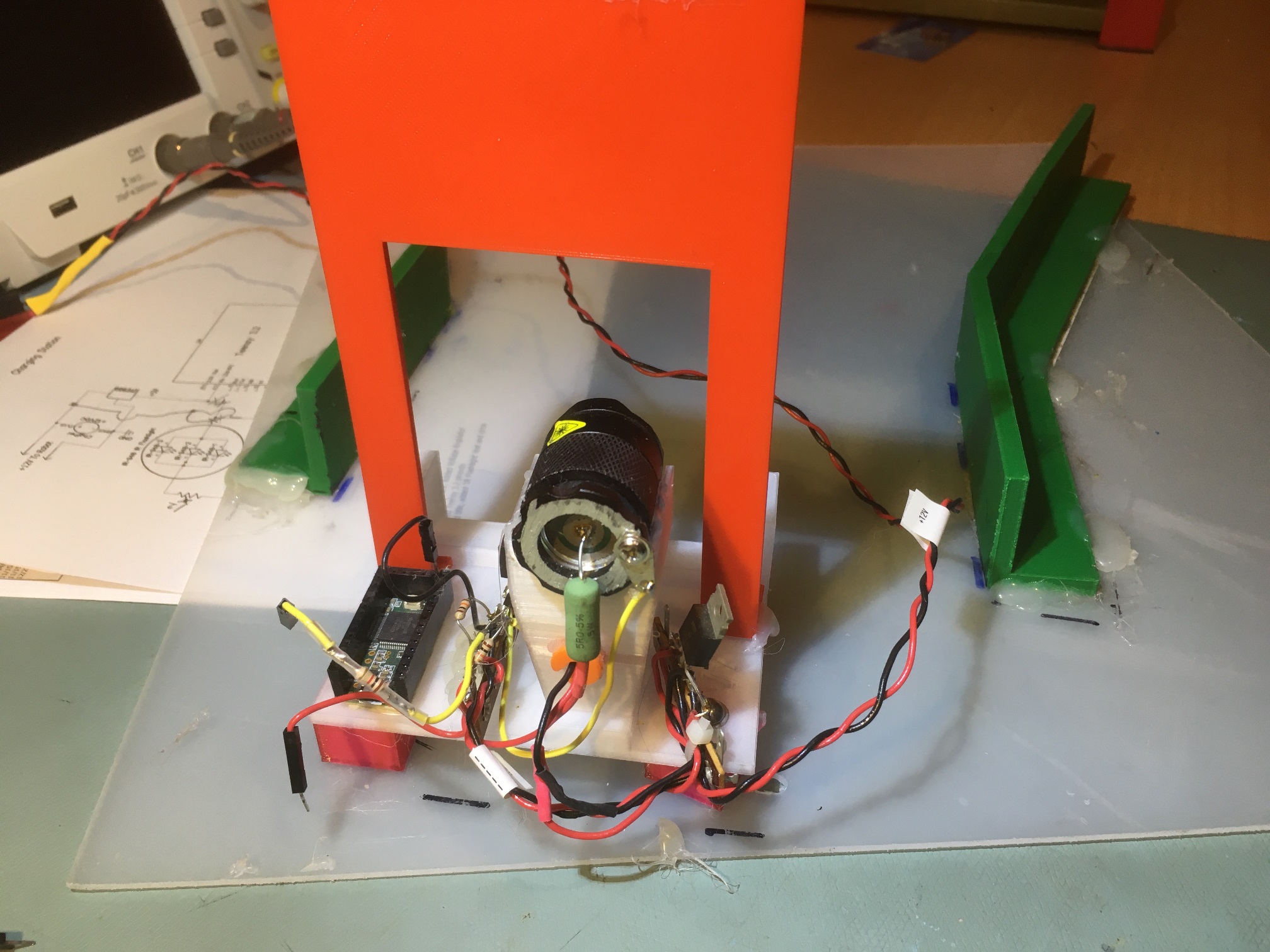
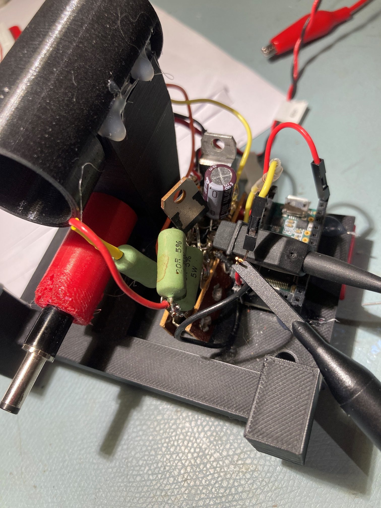
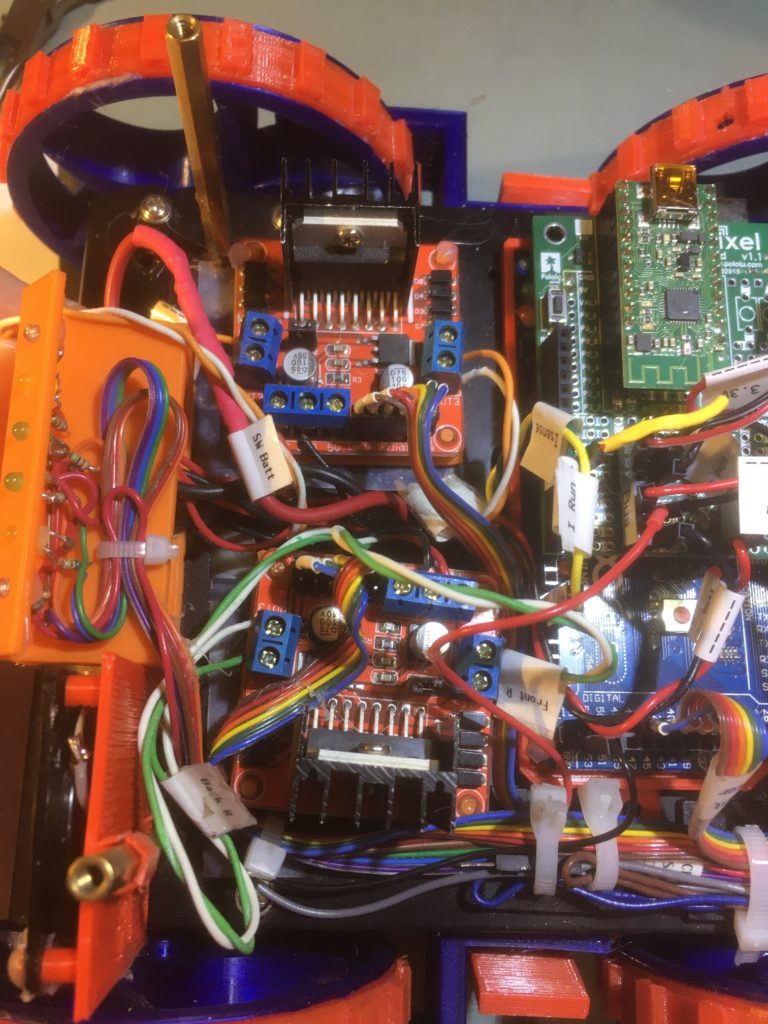
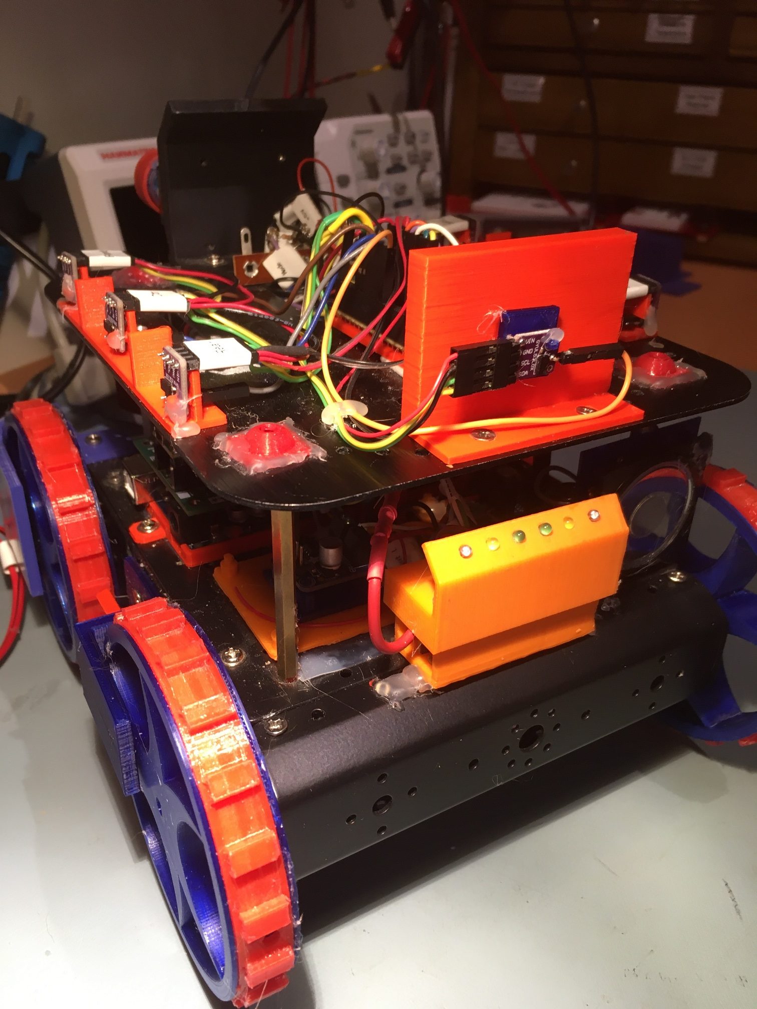
Back in May of last year I started the process of replacing the ultrasonic distance sensors on Wall-E2, my autonomous wall-following robot, with two side-looking arrays of STMicroelectronics’ VL53L0X infrared laser ‘Time-of-Flight’ distance sensor. Later that same year I upgraded the installation by adding a rear distance sensor as well, as shown in the following photo:
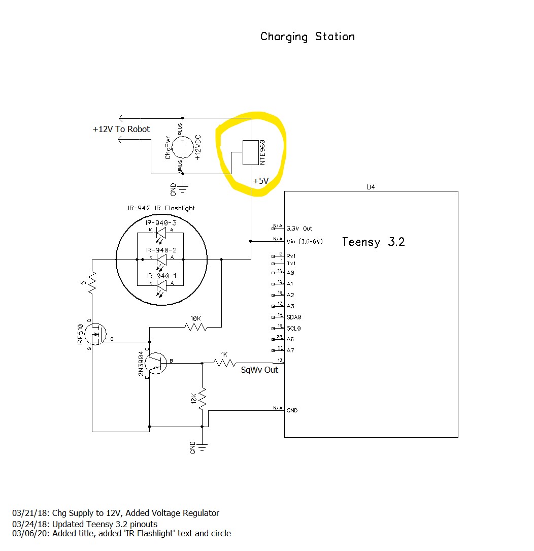
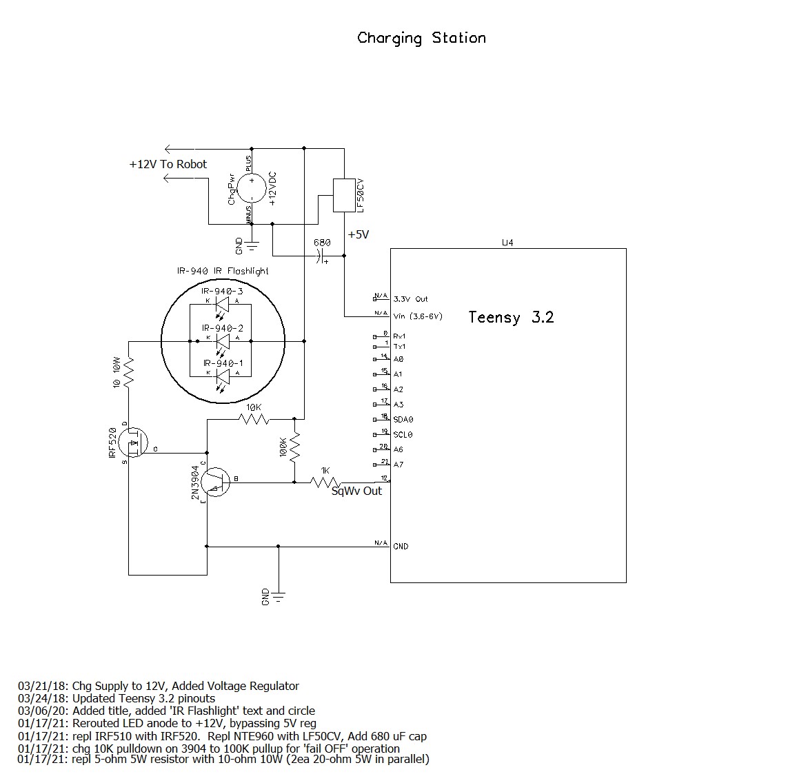
All went swimmingly until I started having problems when Wall-E2 connected up to its charger. Wall-E2 connecting to its charger is a pretty dynamic event, as it has to build up enough speed to make sure the charging probe seats into the charging jack properly. I discovered that about every other time Wall-E2 connected, the distance sensors would start reporting ‘-1’ instead of the actual distances. This meant that when Wall-E2 disconnected from charging, it had no idea what to do or which way to turn. This didn’t happen all the time, but often enough to be very worrisome.
After some head-scratching and program instrumentation I became convinced this was a real issue, and I posted on the ST Micro’s forum about the issue. ST Micro’s VL53L0X expert John E. Kvam answered with this post:
The VL53L0X sensor will not return a -1. The user manual does define a -1 error, but it states that this cannot happen. What does return a -1 is an I2C timeout.
And I think that is what is killing you. The I2C is notorious for being basically unreliable. And the major symptom of a dropped bit (the most likely failure), is that the bus is stuck low. (When nothing is being transmitted both the clock and data lines should be high.) Philips designed the I2C bus and NXP bought Philips. So the NXP site has some documentation on how to tweak the bus. I’d read and understand that.
One other possibility is that one or more of the sensors rebooted – perhaps due to power glitch. If this happens the sensor will revert to it’s base I2C address.
If you’ve changed all your addresses there should be nothing at address 0x29 (0x52/0x53). You could occasionally ping the base address – and if you ever got an answer, you would would know you had a reboot of some kind.
After thinking about this some more, I realized that there is a good chance that the I2C ‘daisy-chain’ wiring and/or the power/ground connections are getting interrupted due to the impulse generated when Wall-E2 hits the charging station stop, and this is causing one or more of the sensors to drop out. I thought I had done a very careful job with the I2C/power ‘daisy-chain’, but I had thought that about a previous effort where I found a faulty ground connection, so I knew it was a possibility.
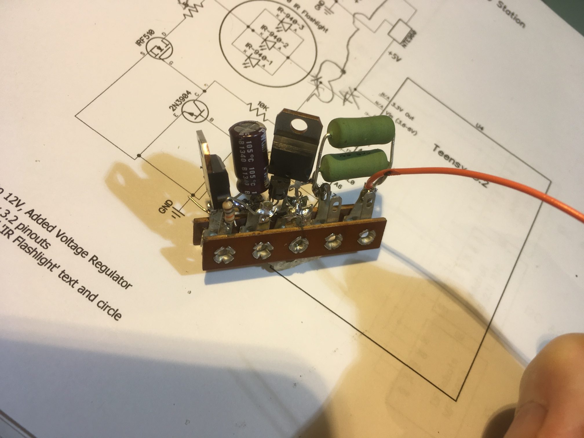
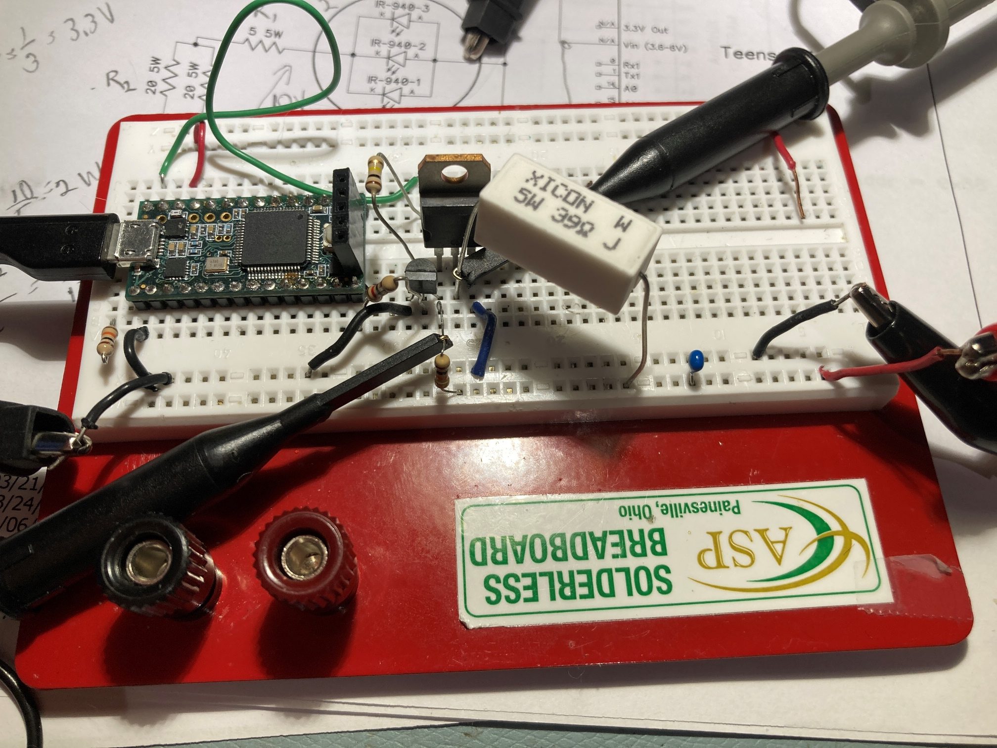
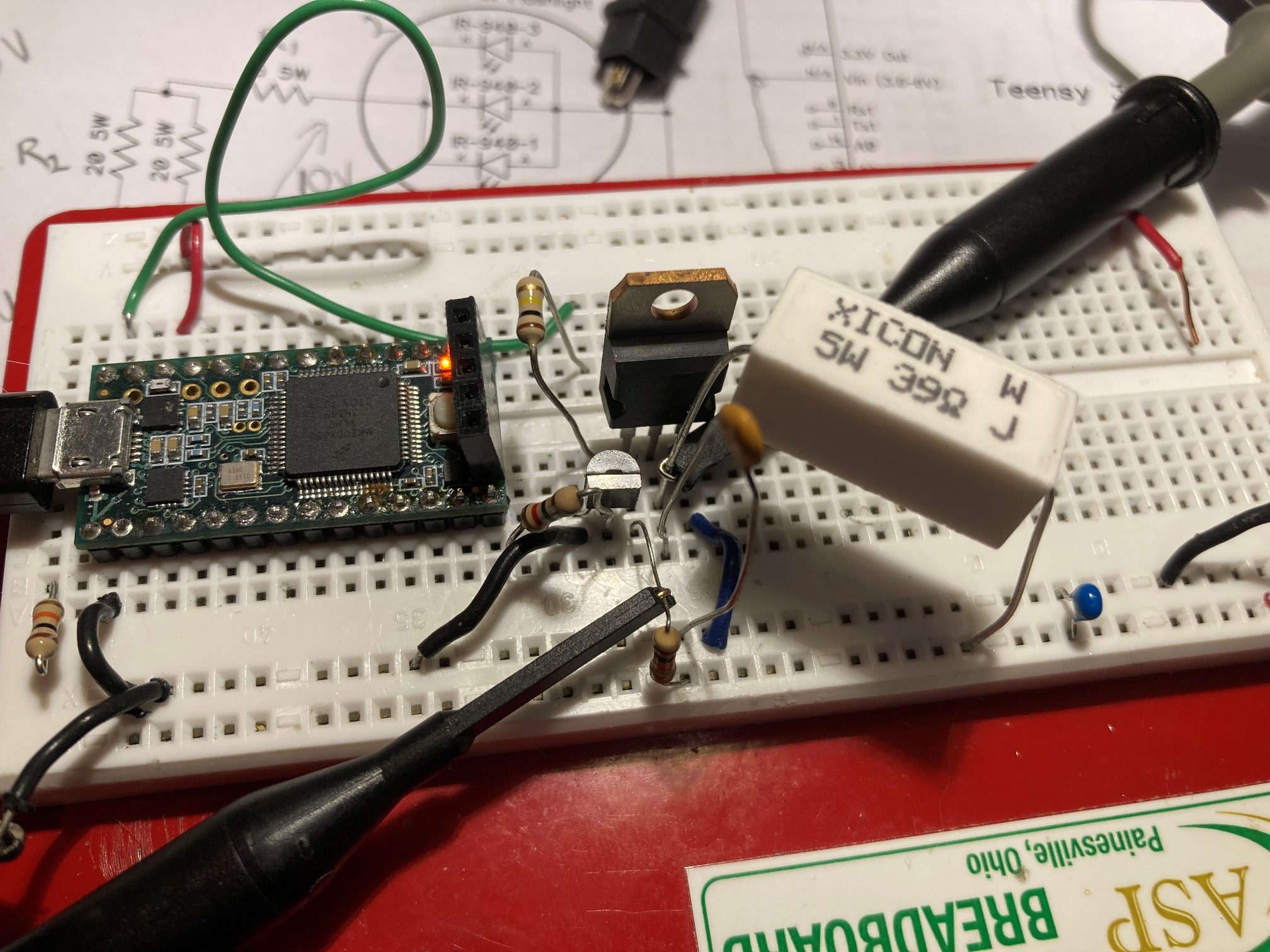
After thinking about this some more, it occurred to me that I could eliminate most of the point-point wiring issues by creating a PCB to house the VL53L0X modules, with a single 4-pin connector for I2C and power. I had made a PCB some years before using DipTrace that had turned out petty well, so making one for the very simple VL53L0X wiring scheme should be a piece of cake.
Well, as it turned out, designing the PCB was the easy part. However, when it came to the part about having the boards actually manufactured, I was in for a bit of a shock. For my previous board I used DipTrace’s ‘baked-in’ manufacturer Bay Area Circuits to purchase 5 boards for around $30, but when I tried this same trick with my new board, the minimum charge for boards from BAC was $150 – ouch!
After a lot of web searching and research, I eventually found the Chinese company JLCPCB and discovered they have a very nice document that shows how to export the required files from DipTrace and upload them to their site. Took me about 30 minutes to go through the process the first time, and now I have my 5ea boards ordered for a grand total of about $15USD. Only a 10:1 ratio from BAC to JLCPCB. I can’t imagine how BAC can stay in business, and I can’t imagine why DipTrace has that company ‘baked in’ and not JLCPCB. DipTrace must be getting a heck of a kickback from BAC!
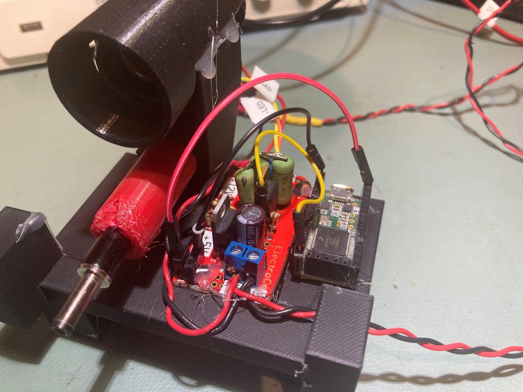
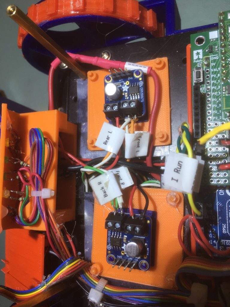
Less than 10 days later, I had the finished PCBs in my hand – wow! Here’s a photo showing two PCB’s installed on Wall-E2. I installed 4-pin headers on both ends of the near PCB in order to daisy-chain the I2C and power connections to the rear distance sensor (hidden behind the red ‘rear bumper’ block in the right background).
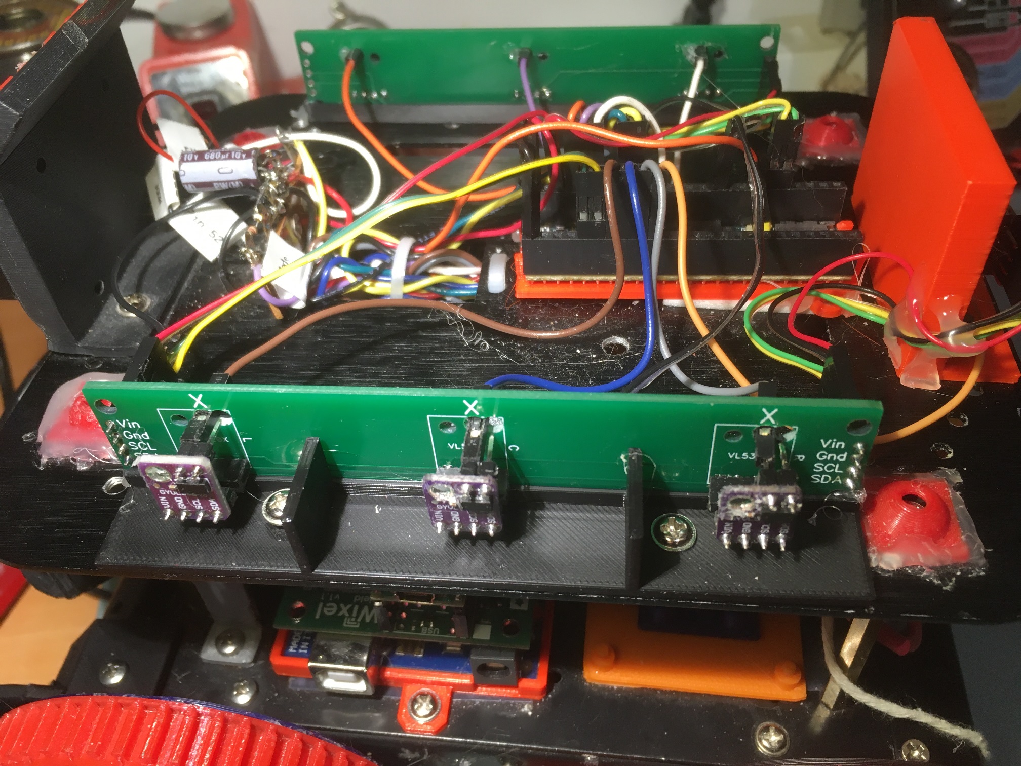
Comparing the ‘before’ and ‘after’ photos, it is easy to see that the PCB installation eliminates two 4-pin connectors and a three-loop daisy chain on one side of the robot, and two 4-pin connectors and a four-loop daisy chain on the other side (the one that also connects to the rear distance sensor. Moreover, now none of the 3 connectors used for all seven sensors has more than one wire per pin.
Hopefully this upgrade will eliminate (or at least significantly suppress) wiring and/or connector issues associated with the charger-connect ‘impulse’ – we’ll see
25 March 2021 Update:
After getting the new PCBs installed and some other connection issues solved, Wall-E2’s sensors seem to be a lot more reliable. However, I decided to take this opportunity to study John Kvam’s idea of re-initializing all seven sensors if one of them happens to show up at the default VL53L0X I2C address.
So, I modified the Teensy 3.5 VL53L0X array management code to abstract the sensor init code from setup() to its own function so it can be called if the program detects a sensor at the default I2C address, and then added code in loop() to do just that. Here’s the detection code:
|
1 2 3 4 5 6 7 8 9 10 11 12 13 |
//03/25/21 see if any VL53L0X responds to a query at the default address Wire1.beginTransmission(DEFAULT_VL53L0X_ADDR); if (!Wire1.endTransmission() != 0) { Serial.printf("Ooops! found a VL53L0X sensor at %x on Wire1!\n", DEFAULT_VL53L0X_ADDR); InitAllSensors(); } Wire2.beginTransmission(DEFAULT_VL53L0X_ADDR); if (!Wire2.endTransmission() != 0) { Serial.printf("Ooops! found a VL53L0X sensor at %x on Wire2!\n", DEFAULT_VL53L0X_ADDR); InitAllSensors(); } |
and here’s the new ‘InitAllSensors()’ routine:
|
1 2 3 4 5 6 7 8 9 10 11 12 13 14 15 16 17 18 19 20 21 22 23 24 25 26 27 28 29 30 31 32 33 34 35 36 37 38 39 40 41 42 43 44 45 46 47 48 49 50 51 52 53 54 55 56 57 58 59 60 61 62 63 64 65 66 67 68 69 70 71 72 73 74 75 76 77 78 79 80 81 82 83 84 85 86 87 88 89 90 91 92 93 94 95 96 97 98 99 100 101 102 103 104 105 106 107 108 109 110 111 112 113 114 115 116 117 118 119 120 121 122 123 124 125 126 127 128 129 130 131 132 133 134 135 136 137 138 139 140 141 142 143 144 145 146 147 148 149 150 151 152 153 154 155 156 157 158 159 160 161 162 163 164 165 166 167 168 169 170 |
bool InitAllSensors() { //Purpose: Initialize all seven VL53L0X sensors //Provenance: 03/22/21 Serial.printf("Initializing VL53L0X Sensor Array Elements\n"); //Put all sensors in reset mode by pulling XSHUT low digitalWrite(RF_XSHUT_PIN, LOW); digitalWrite(RC_XSHUT_PIN, LOW); digitalWrite(RR_XSHUT_PIN, LOW); digitalWrite(LF_XSHUT_PIN, LOW); digitalWrite(LC_XSHUT_PIN, LOW); digitalWrite(LR_XSHUT_PIN, LOW); //added 10/23/20 for rear sensor pinMode(Rear_XSHUT_PIN, OUTPUT); digitalWrite(Rear_XSHUT_PIN, LOW); //now bring lidar_RF only out of reset and set it's address //input w/o pullups sets line to high impedance so XSHUT pullup to 3.3V takes over pinMode(RF_XSHUT_PIN, INPUT); delay(10); bool retval = true; if (!lidar_RF.init()) { Serial.println("Failed to detect and initialize lidar_RF!"); //while (1) {} retval = false; } //from Pololu forum post lidar_RF.setMeasurementTimingBudget(20000); lidar_RF.startContinuous(); lidar_RF.setAddress(DEFAULT_VL53L0X_ADDR + 1); Serial.printf("lidar_RF address is 0x%x\n", lidar_RF.getAddress()); delay(100); //now bring lidar_RC only out of reset, initialize it, and set its address //input w/o pullups sets line to high impedance so XSHUT pullup to 3.3V takes over pinMode(RC_XSHUT_PIN, INPUT); delay(10); if (!lidar_RC.init()) { Serial.println("Failed to detect and initialize lidar_RC!"); //while (1) {} retval = false; } //from Pololu forum post lidar_RC.setMeasurementTimingBudget(20000); lidar_RC.startContinuous(); lidar_RC.setAddress(DEFAULT_VL53L0X_ADDR + 2); Serial.printf("lidar_RC address is 0x%x\n", lidar_RC.getAddress()); delay(100); //now bring lidar_RR only out of reset, initialize it, and set its address //input w/o pullups sets line to high impedance so XSHUT pullup to 3.3V takes over pinMode(RR_XSHUT_PIN, INPUT); delay(10); if (!lidar_RR.init()) { Serial.println("Failed to detect and initialize lidar_RR!"); //while (1) {} retval = false; } //from Pololu forum post lidar_RR.setMeasurementTimingBudget(20000); lidar_RR.startContinuous(); lidar_RR.setAddress(DEFAULT_VL53L0X_ADDR + 3); Serial.printf("lidar_RR address is 0x%x\n", lidar_RR.getAddress()); delay(100); //now bring lidar_LF only out of reset, initialize it, and set its address //input w/o pullups sets line to high impedance so XSHUT pullup to 3.3V takes over pinMode(LF_XSHUT_PIN, INPUT); delay(10); if (!lidar_LF.init()) { Serial.println("Failed to detect and initialize lidar_LF!"); //while (1) {} retval = false; } //from Pololu forum post lidar_LF.setMeasurementTimingBudget(20000); lidar_LF.startContinuous(); lidar_LF.setAddress(DEFAULT_VL53L0X_ADDR + 4); Serial.printf("lidar_LF address is 0x%x\n", lidar_LF.getAddress()); delay(100); //now bring lidar_LC only out of reset, initialize it, and set its address //input w/o pullups sets line to high impedance so XSHUT pullup to 3.3V takes over pinMode(LC_XSHUT_PIN, INPUT); delay(10); if (!lidar_LC.init()) { Serial.println("Failed to detect and initialize lidar_LC!"); //while (1) {} retval = false; } //from Pololu forum post lidar_LC.setMeasurementTimingBudget(20000); lidar_LC.startContinuous(); lidar_LC.setAddress(DEFAULT_VL53L0X_ADDR + 5); Serial.printf("lidar_LC address is 0x%x\n", lidar_LC.getAddress()); delay(100); //now bring lidar_LR only out of reset, initialize it, and set its address //input w/o pullups sets line to high impedance so XSHUT pullup to 3.3V takes over pinMode(LR_XSHUT_PIN, INPUT); if (!lidar_LR.init()) { Serial.println("Failed to detect and initialize lidar_LR!"); //while (1) {} retval = false; } //from Pololu forum post lidar_LR.setMeasurementTimingBudget(20000); lidar_LR.startContinuous(); lidar_LR.setAddress(DEFAULT_VL53L0X_ADDR + 6); Serial.printf("lidar_LR address is 0x%x\n", lidar_LR.getAddress()); delay(100); //added 10/23/20 for rear sensor //now bring lidar_Rear only out of reset, initialize it, and set its address //input w/o pullups sets line to high impedance so XSHUT pullup to 3.3V takes over pinMode(Rear_XSHUT_PIN, INPUT); if (!lidar_Rear.init()) { Serial.println("Failed to detect and initialize lidar_Rear!"); //while (1) {} retval = false; } //from Pololu forum post lidar_Rear.setMeasurementTimingBudget(20000); lidar_Rear.startContinuous(); lidar_Rear.setAddress(DEFAULT_VL53L0X_ADDR + 7); Serial.printf("lidar_Rear address is 0x%x\n", lidar_Rear.getAddress()); return retval; } |
And here is the complete Teensy program for managing the VL53L0X arrays:
|
1 2 3 4 5 6 7 8 9 10 11 12 13 14 15 16 17 18 19 20 21 22 23 24 25 26 27 28 29 30 31 32 33 34 35 36 37 38 39 40 41 42 43 44 45 46 47 48 49 50 51 52 53 54 55 56 57 58 59 60 61 62 63 64 65 66 67 68 69 70 71 72 73 74 75 76 77 78 79 80 81 82 83 84 85 86 87 88 89 90 91 92 93 94 95 96 97 98 99 100 101 102 103 104 105 106 107 108 109 110 111 112 113 114 115 116 117 118 119 120 121 122 123 124 125 126 127 128 129 130 131 132 133 134 135 136 137 138 139 140 141 142 143 144 145 146 147 148 149 150 151 152 153 154 155 156 157 158 159 160 161 162 163 164 165 166 167 168 169 170 171 172 173 174 175 176 177 178 179 180 181 182 183 184 185 186 187 188 189 190 191 192 193 194 195 196 197 198 199 200 201 202 203 204 205 206 207 208 209 210 211 212 213 214 215 216 217 218 219 220 221 222 223 224 225 226 227 228 229 230 231 232 233 234 235 236 237 238 239 240 241 242 243 244 245 246 247 248 249 250 251 252 253 254 255 256 257 258 259 260 261 262 263 264 265 266 267 268 269 270 271 272 273 274 275 276 277 278 279 280 281 282 283 284 285 286 287 288 289 290 291 292 293 294 295 296 297 298 299 300 301 302 303 304 305 306 307 308 309 310 311 312 313 314 315 316 317 318 319 320 321 322 323 324 325 326 327 328 329 330 331 332 333 334 335 336 337 338 339 340 341 342 343 344 345 346 347 348 349 350 351 352 353 354 355 356 357 358 359 360 361 362 363 364 365 366 367 368 369 370 371 372 373 374 375 376 377 378 379 380 381 382 383 384 385 386 387 388 389 390 391 392 393 394 395 396 397 398 399 400 401 402 403 404 405 406 407 408 409 410 411 412 413 414 415 416 417 418 419 420 421 422 423 424 425 426 427 428 429 430 431 432 433 434 435 436 437 438 439 440 441 442 443 444 445 446 447 448 449 450 451 452 453 454 455 456 457 458 459 460 461 462 463 464 465 466 467 468 469 470 471 472 473 474 475 476 477 478 479 480 481 482 483 484 485 486 487 488 489 490 491 492 493 494 495 496 497 498 499 500 501 |
/* Name: Teensy_7VL53L0X_I2C_Slave_V3.ino Created: 1/24/2021 4:03:35 PM Author: FRANKNEWXPS15\Frank This is the 'final' version of the Teensy 3.5 project to manage all seven VL53L0X lidar distance sensors, three on left, three on right, and now including a rear distance sensor. As of this date it was an identical copy of the TeensyHexVL53L0XHighSpeedDemo project, just renamed for clarity. This program was uploaded to the Teensy on Wall-E2's second deck on 1/24/21 Notes: 02/01/21 Added code in requestEvent() to blink LED_BUILTIN when distance data is requested 03/22/21 Abstracted sensor init code from setup() to InitAllSensors() so can use elsewhere */ #include <Wire.h> //using Wire.h here instead of i2c_t3.h for multiple I2C bus access #include <VL53L0X.h> #include "I2C_Anything.h" //local version modified to use Wire.h vs SBWire volatile uint8_t request_type; const int SETUP_DURATION_OUTPUT_PIN = 33; const int REQUEST_EVENT_DURATION_OUTPUT_PIN = 34; bool bTeensyReady = false; enum VL53L0X_REQUEST { VL53L0X_READYCHECK, //added 11/10/20 to prevent bad reads during Teensy setup() VL53L0X_CENTERS_ONLY, VL53L0X_RIGHT, VL53L0X_LEFT, VL53L0X_ALL, //added 08/05/20, chg 'BOTH' to 'ALL' 10/31/20 VL53L0X_REAR_ONLY //added 10/24/20 }; //right side array VL53L0X lidar_RF(&Wire1); VL53L0X lidar_RC(&Wire1); VL53L0X lidar_RR(&Wire1); //left side array VL53L0X lidar_LF(&Wire2); VL53L0X lidar_LC(&Wire2); VL53L0X lidar_LR(&Wire2); //XSHUT required for I2C address init //right side array const int RF_XSHUT_PIN = 23; const int RC_XSHUT_PIN = 22; const int RR_XSHUT_PIN = 21; //left side array const int LF_XSHUT_PIN = 5; const int LC_XSHUT_PIN = 6; const int LR_XSHUT_PIN = 7; const int MAX_LIDAR_RANGE_MM = 1000; //make it obvious when nearest object is out of range //right side array uint16_t RF_Dist_mm; uint16_t RC_Dist_mm; uint16_t RR_Dist_mm; //left side array uint16_t LF_Dist_mm; uint16_t LC_Dist_mm; uint16_t LR_Dist_mm; float RightSteeringVal; float LeftSteeringVal; const int SLAVE_ADDRESS = 0x20; //just a guess for now const int DEFAULT_VL53L0X_ADDR = 0x29; //10/23/20 added rear distance sensor VL53L0X lidar_Rear(&Wire2); //added to Wire2 daisy-chain const int Rear_XSHUT_PIN = 8; uint16_t Rear_Dist_mm; void setup() { // wait until serial port opens ... For 5 seconds max Serial.begin(115200); delay(5000); pinMode(LED_BUILTIN, OUTPUT); bTeensyReady = false; //11/10/20 added to prevent bad data reads by main controller pinMode(SETUP_DURATION_OUTPUT_PIN, OUTPUT); pinMode(REQUEST_EVENT_DURATION_OUTPUT_PIN, OUTPUT); digitalWrite(SETUP_DURATION_OUTPUT_PIN, HIGH); Wire.begin(SLAVE_ADDRESS); //set Teensy Wire0 port up as slave Wire.onRequest(requestEvent); //ISR for I2C requests from master (Mega 2560) Wire.onReceive(receiveEvent); //ISR for I2C data from master (Mega 2560) Wire1.begin(); Wire2.begin(); pinMode(RF_XSHUT_PIN, OUTPUT); pinMode(RC_XSHUT_PIN, OUTPUT); pinMode(RR_XSHUT_PIN, OUTPUT); pinMode(LF_XSHUT_PIN, OUTPUT); pinMode(LC_XSHUT_PIN, OUTPUT); pinMode(LR_XSHUT_PIN, OUTPUT); //03/22/21 sensor init abstracted to function so can call from loop() bool bSensorsOK = InitAllSensors(); Serial.printf("Just after InitAllSensors()\n"); if (!bSensorsOK) { Serial.printf("Sensor initialization failed - quitting!\n"); while (true) { } } Serial.printf("Msec\tLFront\tLCtr\tLRear\tRFront\tRCtr\tRRear\tLSteer\tRSteer\tRear\n"); //02/01/21 now using LED_BUILTIN to provide visible indication of I2C data requests pinMode(LED_BUILTIN, OUTPUT); digitalWrite(SETUP_DURATION_OUTPUT_PIN, LOW); bTeensyReady = true; //11/10/20 added to prevent bad data reads by main controller } void loop() { //from Pololu forum post RF_Dist_mm = lidar_RF.readRangeContinuousMillimeters(); RC_Dist_mm = lidar_RC.readRangeContinuousMillimeters(); RR_Dist_mm = lidar_RR.readRangeContinuousMillimeters(); RightSteeringVal = (RF_Dist_mm - RR_Dist_mm) / 100.f; //rev 06/21/20 see PPalace post //from Pololu forum post LF_Dist_mm = lidar_LF.readRangeContinuousMillimeters(); LC_Dist_mm = lidar_LC.readRangeContinuousMillimeters(); LR_Dist_mm = lidar_LR.readRangeContinuousMillimeters(); LeftSteeringVal = (LF_Dist_mm - LR_Dist_mm) / 100.f; //rev 06/21/20 see PPalace post //added 10/23/20 for rear sensor Rear_Dist_mm = lidar_Rear.readRangeContinuousMillimeters(); Serial.printf("%lu\t%d\t%d\t%d\t%d\t%d\t%d\t%d\n", millis(), RF_Dist_mm, RC_Dist_mm, RR_Dist_mm, LF_Dist_mm, LC_Dist_mm, LR_Dist_mm, Rear_Dist_mm); delay(100); //03/25/21 see if any VL53L0X responds to a query at the default address Wire1.beginTransmission(DEFAULT_VL53L0X_ADDR); if (!Wire1.endTransmission() != 0) { Serial.printf("Ooops! found a VL53L0X sensor at %x on Wire1!\n", DEFAULT_VL53L0X_ADDR); InitAllSensors(); } Wire2.beginTransmission(DEFAULT_VL53L0X_ADDR); if (!Wire2.endTransmission() != 0) { Serial.printf("Ooops! found a VL53L0X sensor at %x on Wire2!\n", DEFAULT_VL53L0X_ADDR); InitAllSensors(); } } // function that executes whenever data is requested by master // this function is registered as an event, see setup() void requestEvent() { //Purpose: Send requested sensor data to the Mega controller via main I2C bus //Inputs: // request_type = uint8_t value denoting type of data requested (from receiveEvent()) // 0 = left & right center distances only // 1 = right side front, center and rear distances, plus steering value // 2 = left side front, center and rear distances, plus steering value // 3 = both side front, center and rear distances, plus both steering values //Outputs: // Requested data sent to master //Notes: // 08/05/20 added VL53L0X_ALL request type to get both sides at once // 10/24/20 added VL53L0X_REAR_ONLY request type // 11/09/20 added write to pin for O'scope monitoring // 02/01/21 aded LED_PIN blink //DEBUG!! //Serial.printf("RequestEvent() with request_type = %d: VL53L0X Front/Center/Rear distances = %d, %d, %d\n", // request_type, RF_Dist_mm, RC_Dist_mm, RR_Dist_mm); //DEBUG!! digitalWrite(REQUEST_EVENT_DURATION_OUTPUT_PIN, HIGH); digitalWrite(LED_BUILTIN, !digitalRead(LED_BUILTIN)); switch (request_type) { case VL53L0X_READYCHECK: //added 11/10/20 to prevent bad reads during Teensy setup() Serial.printf("in VL53L0X_READYCHECK case at %lu with bTeensyReady = %d\n", millis(), bTeensyReady); I2C_writeAnything(bTeensyReady); break; case VL53L0X_CENTERS_ONLY: //DEBUG!! //data_size = 2*sizeof(uint16_t); //Serial.printf("Sending %d bytes LC_Dist_mm = %d, RC_Dist_mm = %d to master\n", data_size, LC_Dist_mm, RC_Dist_mm); //DEBUG!! I2C_writeAnything(RC_Dist_mm); I2C_writeAnything(LC_Dist_mm); break; case VL53L0X_RIGHT: //DEBUG!! //data_size = 3 * sizeof(uint16_t) + sizeof(float); //Serial.printf("Sending %d bytes RF/RC/RR/RS vals = %d, %d, %d, %3.2f to master\n", // data_size, RF_Dist_mm, RC_Dist_mm, RR_Dist_mm, RightSteeringVal); //DEBUG!! I2C_writeAnything(RF_Dist_mm); I2C_writeAnything(RC_Dist_mm); I2C_writeAnything(RR_Dist_mm); I2C_writeAnything(RightSteeringVal); break; case VL53L0X_LEFT: //DEBUG!! //data_size = 3 * sizeof(uint16_t) + sizeof(float); //Serial.printf("Sending %d bytes LF/LC/LR/LS vals = %d, %d, %d, %3.2f to master\n", // data_size, LF_Dist_mm, LC_Dist_mm, LR_Dist_mm, LeftSteeringVal); //DEBUG!! I2C_writeAnything(LF_Dist_mm); I2C_writeAnything(LC_Dist_mm); I2C_writeAnything(LR_Dist_mm); I2C_writeAnything(LeftSteeringVal); break; case VL53L0X_ALL: //added 08/05/20 to get data from both sides at once //10/31/20 chg to VL53L0X_ALL & report all 7 sensor values //DEBUG!! //data_size = 3 * sizeof(uint16_t) + sizeof(float); //Serial.printf("Sending %d bytes LF/LC/LR/LS vals = %d, %d, %d, %3.2f to master\n", // data_size, LF_Dist_mm, LC_Dist_mm, LR_Dist_mm, LeftSteeringVal); //Serial.printf("left %d\t%d\t%d\t%d\t%2.3f", // LF_Dist_mm, LC_Dist_mm, LR_Dist_mm); //DEBUG!! //Serial.printf("In VL53L0X_ALL case\n"); //left side I2C_writeAnything(LF_Dist_mm); I2C_writeAnything(LC_Dist_mm); I2C_writeAnything(LR_Dist_mm); I2C_writeAnything(LeftSteeringVal); //DEBUG!! //data_size = 3 * sizeof(uint16_t) + sizeof(float); //Serial.printf("Sending %d bytes RF/RC/RR/RS vals = %d, %d, %d, %3.2f to master\n", // data_size, RF_Dist_mm, RC_Dist_mm, RR_Dist_mm, LeftSteeringVal); //Serial.printf(" right %d\t%d\t%d\t%d\t%2.3f\n", //RF_Dist_mm, RC_Dist_mm, RR_Dist_mm); //DEBUG!! //right side I2C_writeAnything(RF_Dist_mm); I2C_writeAnything(RC_Dist_mm); I2C_writeAnything(RR_Dist_mm); I2C_writeAnything(RightSteeringVal); //10/31/20 now also reporting rear sensor value I2C_writeAnything(Rear_Dist_mm); break; case VL53L0X_REAR_ONLY: //DEBUG!! //data_size = sizeof(uint16_t); //Serial.printf("Sending %d bytes Rear_Dist_mm = %d to master\n", data_size, Rear_Dist_mm); //DEBUG!! I2C_writeAnything(Rear_Dist_mm); break; default: break; } digitalWrite(REQUEST_EVENT_DURATION_OUTPUT_PIN, LOW); } // // handle Rx Event (incoming I2C data) // void receiveEvent(int numBytes) { //Purpose: capture data request type from Mega I2C master //Inputs: // numBytes = int value denoting number of bytes received from master //Outputs: // uint8_t request_type filled with request type value from master //DEBUG!! //Serial.printf("receiveEvent(%d)\n", numBytes); //DEBUG!! I2C_readAnything(request_type); //DEBUG!! //Serial.printf("receiveEvent: Got %d from master\n", request_type); //DEBUG!! } bool InitAllSensors() { //Purpose: Initialize all seven VL53L0X sensors //Provenance: 03/22/21 Serial.printf("Initializing VL53L0X Sensor Array Elements\n"); //Put all sensors in reset mode by pulling XSHUT low digitalWrite(RF_XSHUT_PIN, LOW); digitalWrite(RC_XSHUT_PIN, LOW); digitalWrite(RR_XSHUT_PIN, LOW); digitalWrite(LF_XSHUT_PIN, LOW); digitalWrite(LC_XSHUT_PIN, LOW); digitalWrite(LR_XSHUT_PIN, LOW); //added 10/23/20 for rear sensor pinMode(Rear_XSHUT_PIN, OUTPUT); digitalWrite(Rear_XSHUT_PIN, LOW); //now bring lidar_RF only out of reset and set it's address //input w/o pullups sets line to high impedance so XSHUT pullup to 3.3V takes over pinMode(RF_XSHUT_PIN, INPUT); delay(10); bool retval = true; if (!lidar_RF.init()) { Serial.println("Failed to detect and initialize lidar_RF!"); //while (1) {} retval = false; } //from Pololu forum post lidar_RF.setMeasurementTimingBudget(20000); lidar_RF.startContinuous(); lidar_RF.setAddress(DEFAULT_VL53L0X_ADDR + 1); Serial.printf("lidar_RF address is 0x%x\n", lidar_RF.getAddress()); delay(100); //now bring lidar_RC only out of reset, initialize it, and set its address //input w/o pullups sets line to high impedance so XSHUT pullup to 3.3V takes over pinMode(RC_XSHUT_PIN, INPUT); delay(10); if (!lidar_RC.init()) { Serial.println("Failed to detect and initialize lidar_RC!"); //while (1) {} retval = false; } //from Pololu forum post lidar_RC.setMeasurementTimingBudget(20000); lidar_RC.startContinuous(); lidar_RC.setAddress(DEFAULT_VL53L0X_ADDR + 2); Serial.printf("lidar_RC address is 0x%x\n", lidar_RC.getAddress()); delay(100); //now bring lidar_RR only out of reset, initialize it, and set its address //input w/o pullups sets line to high impedance so XSHUT pullup to 3.3V takes over pinMode(RR_XSHUT_PIN, INPUT); delay(10); if (!lidar_RR.init()) { Serial.println("Failed to detect and initialize lidar_RR!"); //while (1) {} retval = false; } //from Pololu forum post lidar_RR.setMeasurementTimingBudget(20000); lidar_RR.startContinuous(); lidar_RR.setAddress(DEFAULT_VL53L0X_ADDR + 3); Serial.printf("lidar_RR address is 0x%x\n", lidar_RR.getAddress()); delay(100); //now bring lidar_LF only out of reset, initialize it, and set its address //input w/o pullups sets line to high impedance so XSHUT pullup to 3.3V takes over pinMode(LF_XSHUT_PIN, INPUT); delay(10); if (!lidar_LF.init()) { Serial.println("Failed to detect and initialize lidar_LF!"); //while (1) {} retval = false; } //from Pololu forum post lidar_LF.setMeasurementTimingBudget(20000); lidar_LF.startContinuous(); lidar_LF.setAddress(DEFAULT_VL53L0X_ADDR + 4); Serial.printf("lidar_LF address is 0x%x\n", lidar_LF.getAddress()); delay(100); //now bring lidar_LC only out of reset, initialize it, and set its address //input w/o pullups sets line to high impedance so XSHUT pullup to 3.3V takes over pinMode(LC_XSHUT_PIN, INPUT); delay(10); if (!lidar_LC.init()) { Serial.println("Failed to detect and initialize lidar_LC!"); //while (1) {} retval = false; } //from Pololu forum post lidar_LC.setMeasurementTimingBudget(20000); lidar_LC.startContinuous(); lidar_LC.setAddress(DEFAULT_VL53L0X_ADDR + 5); Serial.printf("lidar_LC address is 0x%x\n", lidar_LC.getAddress()); delay(100); //now bring lidar_LR only out of reset, initialize it, and set its address //input w/o pullups sets line to high impedance so XSHUT pullup to 3.3V takes over pinMode(LR_XSHUT_PIN, INPUT); if (!lidar_LR.init()) { Serial.println("Failed to detect and initialize lidar_LR!"); //while (1) {} retval = false; } //from Pololu forum post lidar_LR.setMeasurementTimingBudget(20000); lidar_LR.startContinuous(); lidar_LR.setAddress(DEFAULT_VL53L0X_ADDR + 6); Serial.printf("lidar_LR address is 0x%x\n", lidar_LR.getAddress()); delay(100); //added 10/23/20 for rear sensor //now bring lidar_Rear only out of reset, initialize it, and set its address //input w/o pullups sets line to high impedance so XSHUT pullup to 3.3V takes over pinMode(Rear_XSHUT_PIN, INPUT); if (!lidar_Rear.init()) { Serial.println("Failed to detect and initialize lidar_Rear!"); //while (1) {} retval = false; } //from Pololu forum post lidar_Rear.setMeasurementTimingBudget(20000); lidar_Rear.startContinuous(); lidar_Rear.setAddress(DEFAULT_VL53L0X_ADDR + 7); Serial.printf("lidar_Rear address is 0x%x\n", lidar_Rear.getAddress()); return retval; } |
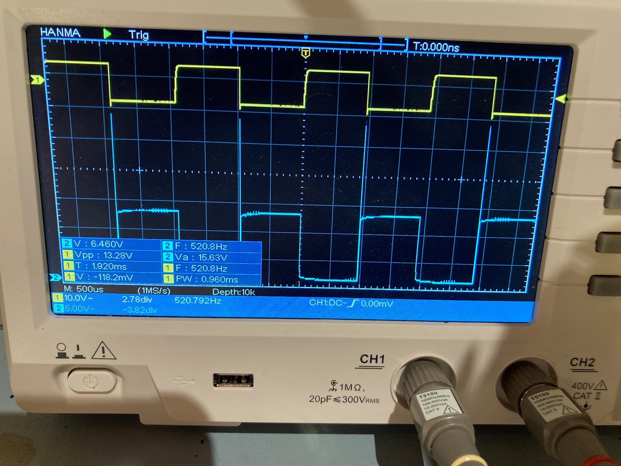
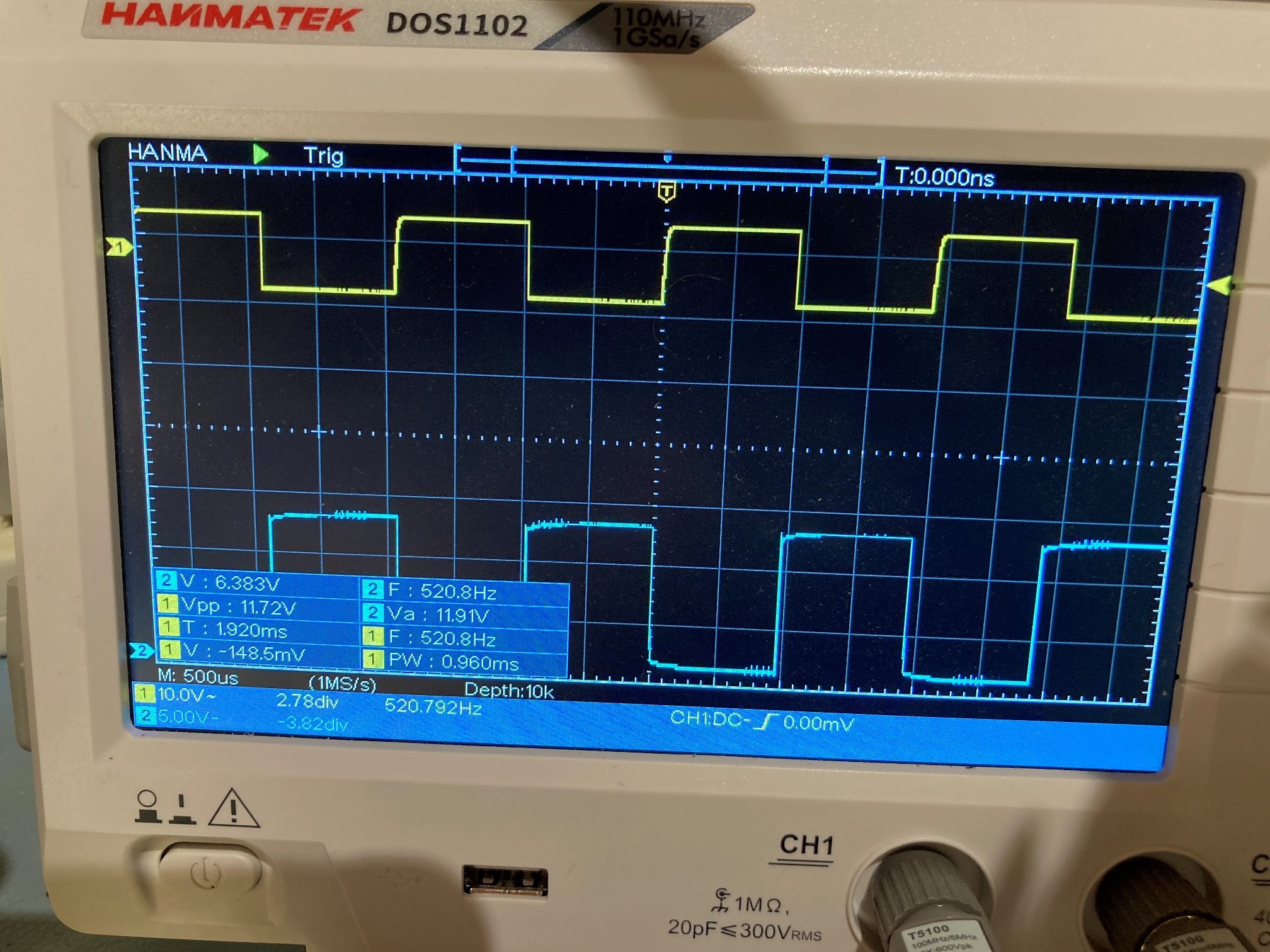
After getting everything set up, I started experimenting. The first thing I tried was momentarily disconnecting one or the other of the two I2C bus connections at the Teensy end. This was interesting in that the affected sensor array results became invalid as soon as the I2C connection was pulled, but resumed valid output as soon as the connection was restored – nice!
Next, I tried momentarily disconnecting the +V line to the arrays. All sensor outputs immediately became invalid, and stayed invalid after +V was restored. In addition, the code in loop() designed to detect one or more VL53L0X sensors at the default address immediately triggered – nice – but the re-initialization code failed to restore valid output.
Here’s the output from a run were the +V line was momentarily disconnected and then reconnected:
|
1 2 3 4 5 6 7 8 9 10 11 12 13 14 15 16 17 18 19 20 21 22 23 24 25 26 27 28 29 30 31 32 33 34 35 36 37 38 39 40 41 42 43 44 45 46 47 48 49 50 51 52 53 54 55 56 57 58 59 60 61 62 63 64 65 66 67 68 69 70 71 72 73 74 75 76 77 78 79 80 81 82 83 84 85 86 87 88 89 90 91 92 93 94 95 96 97 98 99 100 101 102 103 104 105 106 107 108 109 110 111 112 113 114 115 116 117 118 119 120 121 122 123 124 125 126 127 128 129 130 131 132 133 134 135 136 137 138 139 140 141 142 143 144 145 146 147 148 149 150 151 152 153 154 155 156 157 158 159 160 161 162 163 164 165 166 167 168 169 170 171 172 173 174 175 176 177 178 179 180 181 182 183 184 185 186 187 188 189 190 191 192 193 194 195 196 197 198 199 200 201 202 203 204 205 206 207 208 209 210 211 212 213 214 215 216 217 218 219 220 221 222 223 224 225 226 227 228 229 230 231 232 233 234 235 236 237 238 239 240 241 242 243 244 245 246 247 248 249 250 251 252 253 254 255 256 257 258 259 260 261 262 263 264 265 266 267 268 269 270 271 272 273 274 275 276 |
Opening port Port open Initializing VL53L0X Sensor Array Elements lidar_RF address is 0x2a lidar_RC address is 0x2b lidar_RR address is 0x2c lidar_LF address is 0x2d lidar_LC address is 0x2e lidar_LR address is 0x2f lidar_Rear address is 0x30 Just after InitAllSensors() Msec LFront LCtr LRear RFront RCtr RRear LSteer RSteer Rear 6448 373 350 363 544 8191 8190 996 6556 369 344 353 486 8191 8191 1006 6665 371 353 368 475 8191 8190 988 6773 379 352 365 510 512 8190 991 6881 377 346 363 489 8191 8191 1009 6990 368 353 365 541 8191 8191 997 7098 375 350 372 487 8191 8191 989 7206 356 350 366 497 535 8190 983 7315 360 358 364 483 543 8190 997 7423 370 353 363 502 633 8190 1001 7531 373 335 350 465 8191 8190 982 7639 374 349 352 483 497 8191 1017 7748 356 350 381 503 8191 8190 1000 7856 362 350 364 489 585 8191 1013 7964 359 346 380 477 557 8191 979 8073 357 350 361 482 8191 8190 1019 8181 357 347 367 463 8191 8191 1011 8289 374 349 359 459 8191 8190 996 8397 363 348 371 494 8191 8191 1030 8506 365 351 370 557 509 8191 1000 8614 367 345 368 480 445 8191 974 8722 364 354 365 500 8191 8190 987 8831 384 349 356 524 470 8190 1019 8939 376 348 363 539 534 8191 1007 9047 354 349 371 522 475 8191 1020 9156 369 353 362 758 8191 8190 1003 9264 361 347 380 489 8191 8190 981 9372 364 350 367 463 8191 8190 998 9480 366 350 375 505 498 8190 985 9589 382 346 364 445 8191 8190 1004 9697 365 346 373 484 492 8190 996 9805 375 349 353 493 616 8190 1004 9914 371 349 356 538 492 8191 1001 10022 379 346 366 496 503 8191 1016 10130 365 349 354 446 428 8190 1025 10239 381 347 366 474 8191 8191 1008 10347 372 351 362 493 647 8191 1006 10455 366 344 358 487 8191 8191 987 10563 379 346 367 487 566 8191 979 10672 370 348 366 496 8191 8191 975 10780 375 356 360 510 601 8191 1000 10888 370 343 370 497 550 8191 1006 10997 371 352 360 488 8191 8190 982 11105 369 351 353 501 8191 8191 1019 11213 370 345 363 483 8191 8190 1020 11321 372 349 361 503 561 8190 1023 11430 369 351 379 505 453 8191 976 11538 373 347 366 495 8191 8191 988 11646 364 351 372 488 8191 8191 989 11755 365 339 361 470 544 8191 1011 11863 374 358 369 483 8191 8191 1008 11971 367 343 370 490 499 8190 1013 12080 364 348 373 475 491 8191 1006 12188 367 344 363 495 8191 8190 1025 12296 376 349 362 514 580 8191 1035 12404 366 351 365 474 8191 8190 1021 12513 364 350 372 489 8191 8191 1004 12621 373 348 357 494 8191 8190 998 12729 371 352 364 523 8191 8191 1015 12838 365 355 372 500 8191 8190 987 12946 364 357 374 497 8191 8190 998 13054 365 347 364 520 436 8190 990 13163 364 351 381 535 8191 8191 1028 13271 366 345 375 499 8191 8191 1011 13379 358 350 356 482 705 8190 1008 13487 366 350 365 532 590 8191 1008 13596 370 349 355 491 563 8190 1021 13704 364 348 368 517 480 8190 1018 13812 358 348 375 481 8191 8191 1014 13921 363 346 359 503 8191 8191 1004 14029 371 353 363 458 8191 8191 983 14137 376 357 357 565 641 8191 999 14246 360 348 368 548 535 8191 1021 14354 364 347 367 494 601 8191 1002 14462 364 352 372 470 550 8191 991 14570 366 349 366 532 536 8191 1003 14679 374 348 364 493 520 8191 1000 14787 364 345 363 471 8191 8191 1000 14895 364 341 371 503 8191 8190 994 15004 360 349 366 474 605 8191 1030 15112 375 342 356 464 548 8190 986 15220 367 351 364 471 524 8190 1022 15328 365 349 372 491 656 8191 1001 15437 364 347 365 472 8191 8191 993 15545 366 348 365 520 8191 8191 980 15653 374 348 361 527 591 8191 1010 15762 363 352 361 500 609 8190 1002 15870 370 352 370 531 8191 8191 1004 15978 367 353 365 555 8191 8191 987 16087 366 348 365 501 8191 8191 992 16195 366 347 362 481 558 8190 1013 16303 368 352 364 485 8191 8190 1018 16411 372 340 360 459 8003 8191 993 16520 366 357 369 503 561 8191 1009 16628 365 345 364 416 497 8191 986 16736 363 352 362 542 8191 8191 996 16845 373 356 365 455 8191 8190 975 16953 354 342 364 488 551 8191 971 17061 368 349 364 495 8191 8191 983 17170 371 350 367 451 421 8191 1019 17278 367 345 362 465 8191 8190 977 17386 369 351 367 517 604 8190 990 17494 371 342 363 513 8191 8190 999 17603 368 350 365 498 8191 8191 986 17711 362 350 371 509 600 8190 988 17819 366 351 360 515 8191 8190 1002 17928 378 348 364 478 8191 8190 999 18036 367 346 365 436 8191 8191 1035 18144 378 349 356 515 596 8190 1017 18253 365 347 364 491 8191 8191 1018 18361 370 349 367 478 649 8191 1024 18469 370 348 366 443 8191 8190 1002 18577 374 345 366 471 8191 8190 1009 18686 370 355 372 499 8191 8191 1022 18794 362 353 364 480 8191 8191 1003 18902 368 347 365 507 510 8191 1007 19011 373 357 367 486 8191 8190 1029 19119 369 351 362 498 8191 8190 999 19227 360 347 365 445 8191 8190 995 19336 363 351 371 471 557 8190 985 19444 364 354 368 439 707 8190 985 19552 360 354 371 529 8191 8190 994 19660 358 351 373 496 438 8191 992 19769 363 348 366 457 8191 8190 1000 19877 361 358 368 435 689 8190 1005 19985 364 351 371 500 8191 8191 996 20094 368 351 363 478 8191 8190 1029 20202 365 351 370 521 8191 8191 996 20310 373 345 365 514 8191 8191 1009 20418 368 348 367 526 596 8191 959 20527 369 351 351 534 8191 8191 1011 20635 373 346 361 512 8191 8190 989 20743 367 349 367 470 8191 8190 1023 20852 364 344 354 443 586 8191 1027 20960 369 353 375 481 8191 8191 1010 21068 372 354 369 471 461 8190 999 21177 369 353 364 509 8191 8191 977 21285 372 351 366 516 517 8191 1013 21393 370 355 351 515 673 8190 1018 21501 366 351 366 481 8191 8190 1037 21610 374 353 371 547 478 8191 1006 21718 367 354 369 492 8191 8190 991 21826 368 347 359 454 664 8191 982 21935 362 347 370 530 635 8190 997 22043 368 350 368 523 488 8190 984 22151 364 352 363 539 8191 8191 1032 22260 362 348 355 552 8191 8190 995 22368 375 348 357 528 616 8191 996 22476 371 349 357 491 679 8191 1020 22584 370 352 363 539 517 8190 1007 22693 367 346 360 491 8191 8191 1015 22801 366 348 373 524 8191 8190 1003 22909 381 346 371 498 682 8191 1027 23018 373 345 367 528 587 8190 1024 23126 369 341 364 482 8191 8191 1021 23234 372 344 365 532 8191 8190 983 23343 369 352 363 457 8191 8191 1012 23451 370 345 360 448 590 8191 997 23559 364 348 380 523 570 8190 996 23667 378 346 368 509 492 8191 1002 23776 370 348 375 473 8191 8190 1004 23884 371 344 365 457 8191 8190 1001 23992 368 350 375 469 8191 8190 1027 24101 376 353 361 484 8191 8190 1009 24209 373 348 374 529 8191 8190 1015 24317 375 352 368 559 8191 8190 973 24426 369 354 370 541 8191 8191 1003 24534 361 345 366 510 8191 1143 987 24642 364 350 363 420 857 8191 982 24750 367 345 364 496 8191 8190 1021 24859 362 344 370 482 8191 8191 1010 24967 366 346 367 420 503 8191 1005 25075 361 349 372 383 447 8191 981 25184 369 343 371 393 386 8190 1003 25292 367 355 374 360 395 8191 1016 25400 369 342 367 368 392 408 1008 25508 360 352 375 374 376 431 1020 25617 364 355 371 368 352 369 1022 25725 364 346 368 364 322 328 1016 25833 362 348 376 381 320 284 1000 25942 368 343 362 402 331 279 1030 26050 367 352 361 411 333 264 1011 26158 366 349 371 399 364 279 1008 26267 361 356 378 390 367 291 997 26375 365 350 370 373 369 306 1002 26483 372 349 357 367 353 306 980 26591 369 350 371 355 340 300 1002 26700 362 348 372 339 340 297 998 26808 370 353 372 338 325 295 1015 26916 371 351 368 341 331 287 1011 27025 362 344 370 338 325 287 994 27133 369 350 357 334 319 292 1000 27241 371 347 365 328 303 293 972 27349 373 352 365 318 310 293 1013 27458 359 352 374 321 302 283 999 27566 366 347 360 311 308 277 1004 27674 370 348 368 321 303 285 1024 27783 369 349 365 320 315 282 1036 27891 371 352 364 316 307 279 1006 27999 369 346 361 326 295 282 989 28108 367 350 359 312 301 279 1001 28216 373 345 373 315 299 279 1006 28324 368 362 364 306 302 274 989 28432 367 346 365 320 303 284 1025 28541 370 355 363 313 306 277 1003 28649 378 347 369 317 295 280 997 28757 368 348 364 324 307 274 1011 28866 377 349 362 330 300 285 1007 28974 371 352 366 326 307 291 998 29104 65535 65535 65535 65535 65535 65535 65535 29224 65535 65535 65535 65535 65535 65535 65535 29418 65535 65535 65535 65535 65535 65535 65535 Ooops! found a VL53L0X sensor at 29 on Wire1! Initializing VL53L0X Sensor Array Elements Failed to detect and initialize lidar_RF! lidar_RF address is 0x2a Failed to detect and initialize lidar_RC! lidar_RC address is 0x2b Failed to detect and initialize lidar_RR! lidar_RR address is 0x2c Failed to detect and initialize lidar_LF! lidar_LF address is 0x2d Failed to detect and initialize lidar_LC! lidar_LC address is 0x2e Failed to detect and initialize lidar_LR! lidar_LR address is 0x2f Failed to detect and initialize lidar_Rear! lidar_Rear address is 0x30 Ooops! found a VL53L0X sensor at 29 on Wire2! 30190 65535 65535 65535 65535 65535 65535 65535 Ooops! found a VL53L0X sensor at 29 on Wire1! Initializing VL53L0X Sensor Array Elements Failed to detect and initialize lidar_RF! lidar_RF address is 0x2a Failed to detect and initialize lidar_RC! lidar_RC address is 0x2b Failed to detect and initialize lidar_RR! lidar_RR address is 0x2c Failed to detect and initialize lidar_LF! lidar_LF address is 0x2d Failed to detect and initialize lidar_LC! lidar_LC address is 0x2e Failed to detect and initialize lidar_LR! lidar_LR address is 0x2f Failed to detect and initialize lidar_Rear! lidar_Rear address is 0x30 Ooops! found a VL53L0X sensor at 29 on Wire2! 30962 65535 65535 65535 65535 65535 65535 65535 Ooops! found a VL53L0X sensor at 29 on Wire1! Initializing VL53L0X Sensor Array Elements Failed to detect and initialize lidar_RF! lidar_RF address is 0x2a Failed to detect and initialize lidar_RC! lidar_RC address is 0x2b Failed to detect and initialize lidar_RR! lidar_RR address is 0x2c Failed to detect and initialize lidar_LF! lidar_LF address is 0x2d Failed to detect and initialize lidar_LC! lidar_LC address is 0x2e Failed to detect and initialize lidar_LR! lidar_LR address is 0x2f Failed to detect and initialize lidar_Rear! lidar_Rear address is 0x30 |
28 March 2021 Update:
I have been continuing to work on the ‘re-initialize after power interruption’ idea for my VL53L0X sensor array, and while I haven’t come up with a very good solution, I have learned some things:
- The VL53L0X reverts to it’s default (0x29) I2C address immediately when power is removed, but will actually respond to a 0x29 query even after power has been removed. Apparently, the module can draw enough current from the I2C connections to continue to operate (albeit at the default address).
- A ‘powered down’ (power disconnected, but I2C leads still connected) will also respond to distance measurement requests, but will return a nonsense number (65535).
- In order to get a VL53L0X sensor to stop responding, the power lead must be physically grounded – just disconnecting isn’t enough.
- If I use a digital output to power the array, I can turn the power on and off programmatically. Using this tool:
- Turning power OFF causes distance measurements to return ‘65535’ (because this is the same as connecting the power lead to GND). However, this isn’t the normal failure mode; the normal failure mode for power disconnections is an open-circuit – not GND
- Turning power back ON again causes the system to detect that one or more VL53L0X units has appeared at the default I2C address. This probably means I could successfully re-initialize all modules.
So, it looks like I can’t really protect against an arbitrary length power disconnect scenario, as I can’t tell when the power has been restored. All I can do is have the program detect the ‘65535’ distance value, wait for some time (a few seconds?) and then try to re-initialize the sensors. This is, unfortunately, a one-shot deal, as if power hasn’t been restored when the re-init procedure is executed, the initialization code hangs up permanently.
Stay tuned!
Frank