Posted 18 July 2020
In my continuing effort to update Wall-E2’s superpowers, I have been trying to replace the HC-SR04 ‘ping’ sensors with ST Microelectronics VL53L0X Time-of-Flight (ToF) sensors, as implemented by the popular GY530 modules available on eBay.
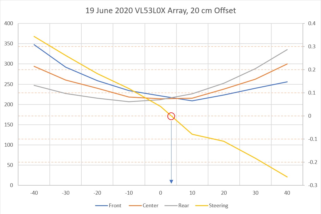
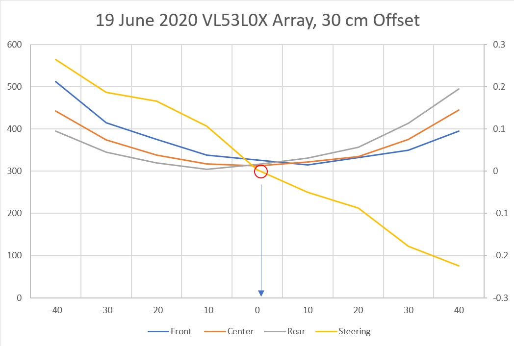
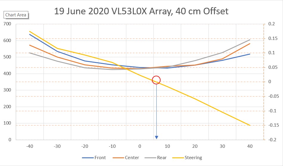
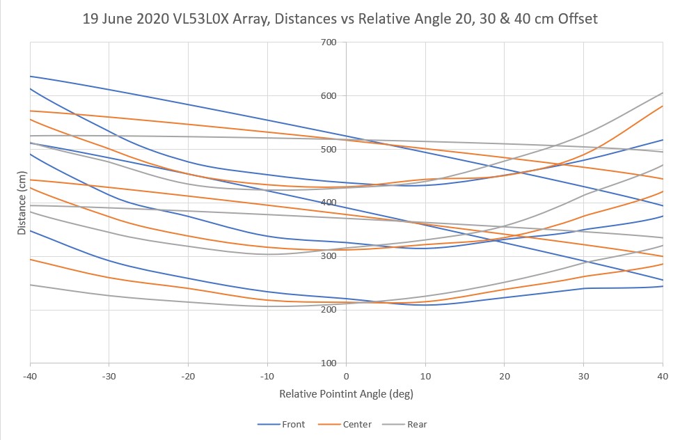
First, I got a 3-element array working and demonstrated effective parallel-heading determination and wall tracking, as described in this post.
Next, I added a second 3-element array on the other side of the robot, but I have been running into trouble getting both arrays to work properly at the same time. Somehow there seems to be some interaction between the two arrays that I can’t seem to nail down.
- I have determined that all six elements respond properly when operated individually or as a member of a 3-element array
- Adding a 4th element to the array causes one or more of the first three elements to respond with an out-of-range measurement
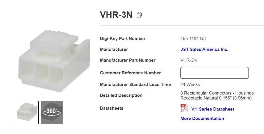
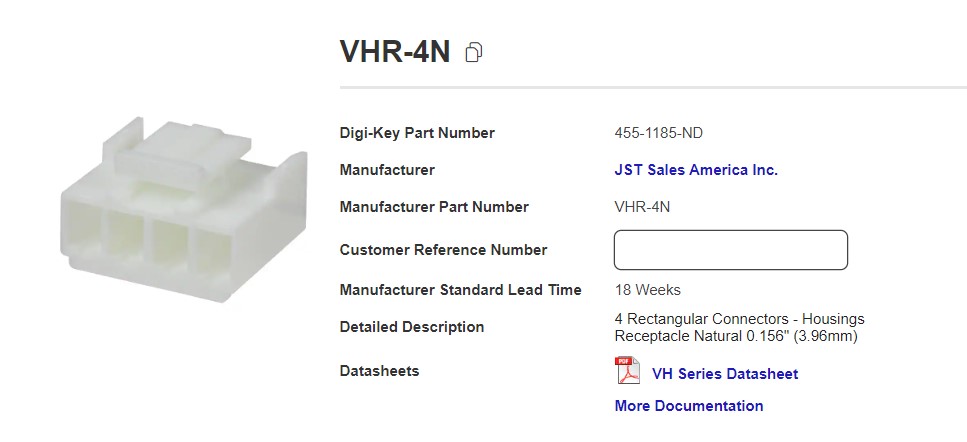
- Adding 2.2K pullups to the I2C bus makes the problem worse, not better. After some investigation, I discovered that the GY530 module already has 10K pullups included, so three modules on the bus would reduce the pullups to 3.3K, and four would already reduce the value to 2.5K. Adding a 2.2K in parallel with 3.3 or 2.5K would drive the value down to around 1.2-1.5K. However, that did lead me to my next idea – using separate I2C busses for the left and right 3-element arrays.
- Moved the left-hand 3-element array from the Wire1 I2C bus to the Wire2 I2C bus. Now the 10K pullups shouldn’t be an issue, as I had already demonstrated proper operation of a 3-element array on the Wire1 I2C bus. Unfortunately, this exhibited similar problems; When running all six elements, all three left-side elements measure properly, but only one right-side element produces reasonable values – the other two give nonsense readings.
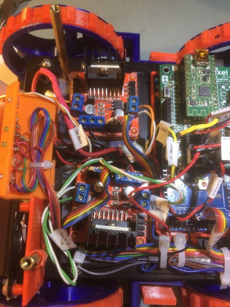
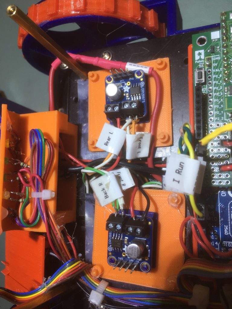
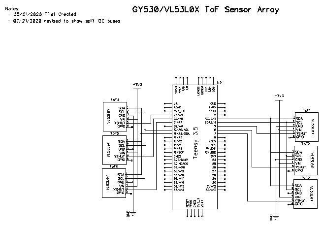
Here’s a photo of the top deck of my autonomous wall-following robot, with the two 3-element arrays installed on the Wire1 and Wire2 I2C busses of a Teensy 3.5.
two 3-element VL53L0X arrays installed on a Teensy 3.5 Wire1 & Wire2 busses
And here is the schematic for the split-bus configuration:
A typical output sequence follows: The first column is milliseconds since program start, and the following 6 columns are the front, center, and rear sensor measurements for the right & left arrays, respectively.
1 2 3 4 5 6 7 8 9 10 11 12 13 14 15 16 17 18 |
Msec Front Center Rear Front Center Rear 9502 1000 1000 133 642 342 379 10396 1000 1000 135 621 334 375 11290 1000 1000 136 1000 340 375 12184 1000 1000 134 667 328 359 13078 1000 1000 133 680 321 377 13973 1000 1000 139 632 335 382 14866 1000 1000 26 592 329 386 15760 1000 1000 28 619 327 383 16654 1000 1000 33 618 333 363 17547 1000 1000 137 64 56 32 18441 1000 1000 138 33 46 28 19334 1000 1000 140 33 43 29 20227 1000 1000 138 36 40 25 21121 1000 1000 140 34 41 23 22015 1000 1000 133 674 293 364 22909 1000 1000 136 615 292 383 23803 1000 1000 139 655 288 384 |
In the above, the data from the first two sensors on the right side is invalid, but all the rest show ‘real’ values.
If the left-side array is disconnected (unplugged) from the Wire2 bus and the program modified to not initialize/measure the left-side array, then the right-side array reads normally, as shown below
1 2 3 4 5 6 7 8 9 10 11 12 13 14 15 16 17 18 19 20 21 |
Msec Front Center Rear 8182 115 148 102 8765 117 149 103 9349 118 146 100 9932 114 148 100 10515 118 150 100 11098 52 21 28 11680 52 21 27 12262 52 20 103 12846 95 106 52 13428 49 16 31 14010 51 17 27 14593 100 149 116 15176 50 29 23 15758 50 21 118 16341 114 167 117 16925 112 162 114 17508 114 162 116 18092 114 170 117 18675 118 170 115 19258 111 161 113 |
If the right-side array is disconnected (unplugged) from the Wire1 bus and the program modified to not initialize/measure the right-side array, then the left-side array reads normally, as shown below
1 2 3 4 5 6 7 8 9 10 11 12 13 14 15 16 17 18 19 20 21 22 23 24 25 26 |
Msec Front Center Rear 8216 1000 487 1000 8785 1000 450 728 9353 1000 495 1000 9921 1000 495 1000 10490 1000 556 1000 11058 1000 521 33 11625 41 42 28 12192 35 40 26 12759 37 43 25 13327 71 208 1000 13895 1000 220 716 14463 1000 216 1000 15031 1000 219 30 15598 47 47 23 16165 47 49 27 16732 76 85 53 17300 92 116 96 17868 131 146 135 18436 178 262 658 19004 1000 334 1000 19572 1000 325 1000 20140 1000 348 1000 20708 1000 372 680 21276 1000 326 1000 21844 1000 328 806 |
Here’s the code being used to drive just the left-side VL53L0X array (right-side array code commented out and the right-side array physically disconnected from the Teensy 3.5):
1 2 3 4 5 6 7 8 9 10 11 12 13 14 15 16 17 18 19 20 21 22 23 24 25 26 27 28 29 30 31 32 33 34 35 36 37 38 39 40 41 42 43 44 45 46 47 48 49 50 51 52 53 54 55 56 57 58 59 60 61 62 63 64 65 66 67 68 69 70 71 72 73 74 75 76 77 78 79 80 81 82 83 84 85 86 87 88 89 90 91 92 93 94 95 96 97 98 99 100 101 102 103 104 105 106 107 108 109 110 111 112 113 114 115 116 117 118 119 120 121 122 123 124 125 126 127 128 129 130 131 132 133 134 135 136 137 138 139 140 141 142 143 144 145 146 147 148 149 150 151 152 153 154 155 156 157 158 159 160 161 162 163 164 165 166 167 168 169 170 171 172 173 174 175 176 177 178 179 180 181 182 183 184 185 186 187 188 189 190 191 192 193 194 195 196 197 198 199 200 201 202 203 204 205 206 207 208 209 210 211 212 213 214 215 216 217 218 219 220 221 222 223 224 225 226 227 228 229 230 231 232 233 234 235 236 237 238 239 240 241 242 243 244 245 246 247 248 249 250 251 252 253 254 255 256 257 258 259 260 261 262 263 264 265 266 267 268 269 270 271 272 273 274 275 276 277 278 279 280 281 282 283 284 285 286 287 288 289 290 291 292 293 294 295 296 297 298 299 300 301 302 303 304 305 306 307 308 309 310 311 312 313 314 315 316 317 318 319 |
/* Name: Teensy_Hex_V53L0X.ino Created: 7/16/2020 2:56:35 PM Author: FRANKNEWXPS15\Frank Notes: 07/18/20: I discovered that only 3 VL53L0X units can share the I2C bus. The GY530 modules have internal 10K pullups on the I2C lines, and the 4th one on the bus reduces the combined pullup value too much. Instead, I put the right-hand array of 3 on Wire1 and the left-hand array of 3 on Wire2. */ /* Name: Teensy_Triple_VL53L0X_V2.ino Created: 5/23/2020 1:16:52 PM Author: FRANKNEWXPS15\Frank */ /* This code copied from the following post on the Adafruit forum: https://forums.adafruit.com/viewtopic.php?f=19&t=164589&p=808693&hilit=vl53l0x#p808693 And adapted to use it on the Wire1 I2C bus on a Teensy 3.5 */ #include <Wire.h> #include "Adafruit_VL53L0X.h" Adafruit_VL53L0X lidar_RF = Adafruit_VL53L0X(); //Right-front LIDAR (angled 30 deg forward) Adafruit_VL53L0X lidar_RC = Adafruit_VL53L0X(); //Right-center LIDAR Adafruit_VL53L0X lidar_RR = Adafruit_VL53L0X(); //Right-rear LIDAR (angled 30 deg rearward) //07/16/20 added three left-side sensors Adafruit_VL53L0X lidar_LF = Adafruit_VL53L0X(); //Left-front LIDAR (angled 30 deg forward) Adafruit_VL53L0X lidar_LC = Adafruit_VL53L0X(); //Left-center LIDAR Adafruit_VL53L0X lidar_LR = Adafruit_VL53L0X(); //left-rear LIDAR (angled 30 deg rearward) //XSHUT required for I2C address init const int RF_XSHUT_PIN = 23; const int RC_XSHUT_PIN = 22; const int RR_XSHUT_PIN = 21; const int LF_XSHUT_PIN = 5; const int LC_XSHUT_PIN = 6; const int LR_XSHUT_PIN = 7; const int RED_LASER_PIN = 0; const int MAX_LIDAR_RANGE_MM = 1000; //make it obvious when nearest object is out of range uint16_t RF_Dist_mm; uint16_t RC_Dist_mm; uint16_t RR_Dist_mm; uint16_t LF_Dist_mm; uint16_t LC_Dist_mm; uint16_t LR_Dist_mm; void setup() { Serial.begin(115200); //Teensy ignores rate parameter pinMode(RF_XSHUT_PIN, OUTPUT); pinMode(RC_XSHUT_PIN, OUTPUT); pinMode(RR_XSHUT_PIN, OUTPUT); pinMode(LF_XSHUT_PIN, OUTPUT); pinMode(LC_XSHUT_PIN, OUTPUT); pinMode(LR_XSHUT_PIN, OUTPUT); pinMode(RED_LASER_PIN, OUTPUT); // wait until serial port opens for native USB devices while (!Serial) { delay(1); } delay(5000); //05/28/20 - this delay is necessary AFTER Serial instantiation! Serial.printf("Teensy Triple VL53L0X V2\n"); //initialize all six LIDAR sensors // 1. Reset all sensors by setting all of their XSHUT pins low for delay(10), then set // all XSHUT high to bring out of reset //right side digitalWrite(RF_XSHUT_PIN, LOW); delay(10); digitalWrite(RC_XSHUT_PIN, LOW); delay(10); digitalWrite(RR_XSHUT_PIN, LOW); delay(10); //left side digitalWrite(LF_XSHUT_PIN, LOW); delay(10); digitalWrite(LC_XSHUT_PIN, LOW); delay(10); digitalWrite(LR_XSHUT_PIN, LOW); delay(10); //right side digitalWrite(RF_XSHUT_PIN, HIGH); digitalWrite(RC_XSHUT_PIN, HIGH); digitalWrite(RR_XSHUT_PIN, HIGH); //left side digitalWrite(LF_XSHUT_PIN, HIGH); digitalWrite(LC_XSHUT_PIN, HIGH); digitalWrite(LR_XSHUT_PIN, HIGH); delay(1000); // 2. Keep sensor #1 awake by keeping XSHUT pin high, and put all other sensors into // shutdown by pulling XSHUT pins low //right side digitalWrite(RC_XSHUT_PIN, LOW); digitalWrite(RR_XSHUT_PIN, LOW); //left side digitalWrite(LF_XSHUT_PIN, LOW); digitalWrite(LC_XSHUT_PIN, LOW); digitalWrite(LR_XSHUT_PIN, LOW); // 4. Initialize sensor #1 //if (!lidar_RF.begin(VL53L0X_I2C_ADDR + 1, false, &Wire1)) //if (!lidar_RF.begin(VL53L0X_I2C_ADDR + 1, true, &Wire1)) //{ // Serial.println(F("Failed to boot lidar_RF")); // while (1); //} //// 5. Keep sensor #1 awake, and now bring sensor #2 out of reset by setting its XSHUT pin high. //// 6. Initialize sensor #2 with lox.begin(new_i2c_address) Pick any number but 0x29 and whatever //// you set the first sensor to //digitalWrite(RC_XSHUT_PIN, HIGH); ////if (!lidar_RC.begin(VL53L0X_I2C_ADDR + 2, false, &Wire1)) //if (!lidar_RC.begin(VL53L0X_I2C_ADDR + 2, true, &Wire1)) //{ // Serial.println(F("Failed to boot lidar_RC")); // while (1); //} //// 7. Repeat for each sensor, turning each one on, setting a unique address. //digitalWrite(RR_XSHUT_PIN, HIGH); ////if (!lidar_RR.begin(VL53L0X_I2C_ADDR + 3, false, &Wire1)) //if (!lidar_RR.begin(VL53L0X_I2C_ADDR + 3, true, &Wire1)) //{ // Serial.println(F("Failed to boot lidar_RR")); // while (1); //} //07/15/20 do same thing for left side sensors // 2. Keep sensor #1 awake by keeping XSHUT pin high, and put all other sensors into // shutdown by pulling XSHUT pins low // 4. Initialize sensor #1 digitalWrite(LF_XSHUT_PIN, HIGH); //if (!lidar_LF.begin(VL53L0X_I2C_ADDR + 4, false, &Wire1)) if (!lidar_LF.begin(VL53L0X_I2C_ADDR + 4, true, &Wire2)) { Serial.println(F("Failed to boot lidar_LF")); while (1); } // 5. Keep sensor #1 awake, and now bring sensor #2 out of reset by setting its XSHUT pin high. // 6. Initialize sensor #2 with lox.begin(new_i2c_address) Pick any number but 0x29 and whatever // you set the first sensor to digitalWrite(LC_XSHUT_PIN, HIGH); if (!lidar_LC.begin(VL53L0X_I2C_ADDR + 5, false, &Wire2)) { Serial.println(F("Failed to boot lidar_RC")); while (1); } // 7. Repeat for each sensor, turning each one on, setting a unique address. digitalWrite(LR_XSHUT_PIN, HIGH); if (!lidar_LR.begin(VL53L0X_I2C_ADDR + 6, false, &Wire2)) { Serial.println(F("Failed to boot lidar_LR")); while (1); } //turn the laser OFF digitalWrite(RED_LASER_PIN, LOW); Serial.printf("\nInit complete\n \nVL53L0X API Simple Ranging example\n \n"); ////05/23/20 experiment with accessing API functions //VL53L0X_Dev_t RightFrontDevice = lidar_RF.GetDeviceHandle(); //VL53L0X_DeviceInfo_t RightFrontDeviceInfo = lidar_RF.GetDeviceInfo(); //Serial.printf("Device Info for Right Front Sensor\n"); //Serial.printf("\tName = %s\n\tType = %s\n\tProdID = %s\n\tType Number = %d\n\tMajor Rev = %d\n\tMinor Rev = %d\n \n", // RightFrontDeviceInfo.Name, RightFrontDeviceInfo.Type, // RightFrontDeviceInfo.ProductId, RightFrontDeviceInfo.ProductType, // RightFrontDeviceInfo.ProductRevisionMajor, RightFrontDeviceInfo.ProductRevisionMinor); ////get measurement timing budget? //prog_uint32_t MeasBudgetUSec; ////VL53L0X_Error ApiError = VL53L0X_GetMeasurementTimingBudgetMicroSeconds(&RightFrontDevice, &MeasBudgetUSec); //VL53L0X_GetMeasurementTimingBudgetMicroSeconds(&RightFrontDevice, &MeasBudgetUSec); //Serial.printf("Right Front Measurement Budget (uSec) = %d\n", MeasBudgetUSec); //delay(1000); //Serial.printf("Changing budget from %d to %d....\n", MeasBudgetUSec, 2 * MeasBudgetUSec); //delay(1000); //MeasBudgetUSec = 2 * MeasBudgetUSec; ////ApiError = VL53L0X_SetMeasurementTimingBudgetMicroSeconds(&RightFrontDevice, MeasBudgetUSec); //VL53L0X_SetMeasurementTimingBudgetMicroSeconds(&RightFrontDevice, MeasBudgetUSec); //Serial.printf("Right Front Measurement Budget (uSec) Now = %d\n \n", MeasBudgetUSec); Serial.printf("Msec\tFront\tCenter\tRear\tSteer\n"); } void loop() { //VL53L0X_RangingMeasurementData_t measure1; //VL53L0X_RangingMeasurementData_t measure2; //VL53L0X_RangingMeasurementData_t measure3; VL53L0X_RangingMeasurementData_t measure4; VL53L0X_RangingMeasurementData_t measure5; VL53L0X_RangingMeasurementData_t measure6; //turn the laser ON digitalWrite(RED_LASER_PIN, HIGH); //lidar_RF.rangingTest(&measure1, false); // pass in 'true' to get debug data printout! ////lidar_RF.rangingTest(&measure1, true); // pass in 'true' to get debug data printout! //if (measure1.RangeStatus != 4) // phase failures have incorrect data //{ // RF_Dist_mm = measure1.RangeMilliMeter; // if (RF_Dist_mm > MAX_LIDAR_RANGE_MM) RF_Dist_mm = MAX_LIDAR_RANGE_MM; //} //else RF_Dist_mm = 0; //delay(100); //lidar_RC.rangingTest(&measure2, false); // pass in 'true' to get debug data printout! ////lidar_RC.rangingTest(&measure2, true); // pass in 'true' to get debug data printout! //if (measure2.RangeStatus != 4) // phase failures have incorrect data //{ // RC_Dist_mm = measure2.RangeMilliMeter; // if (RC_Dist_mm > MAX_LIDAR_RANGE_MM) RC_Dist_mm = MAX_LIDAR_RANGE_MM; //} //else RC_Dist_mm = 0; //delay(100); //lidar_RR.rangingTest(&measure3, false); // pass in 'true' to get debug data printout! ////lidar_RR.rangingTest(&measure3, true); // pass in 'true' to get debug data printout! //if (measure3.RangeStatus != 4) // phase failures have incorrect data //{ // RR_Dist_mm = measure3.RangeMilliMeter; // if (RR_Dist_mm > MAX_LIDAR_RANGE_MM) RR_Dist_mm = MAX_LIDAR_RANGE_MM; //} //else RR_Dist_mm = 0; ////07/16/20 added left side lidar_LF.rangingTest(&measure4, false); // pass in 'true' to get debug data printout! //lidar_LF.rangingTest(&measure4, true); // pass in 'true' to get debug data printout! if (measure4.RangeStatus != 4) // phase failures have incorrect data { LF_Dist_mm = measure4.RangeMilliMeter; if (LF_Dist_mm > MAX_LIDAR_RANGE_MM) LF_Dist_mm = MAX_LIDAR_RANGE_MM; } else LF_Dist_mm = 0; delay(100); lidar_LC.rangingTest(&measure5, false); // pass in 'true' to get debug data printout! if (measure5.RangeStatus != 4) // phase failures have incorrect data { LC_Dist_mm = measure5.RangeMilliMeter; if (LC_Dist_mm > MAX_LIDAR_RANGE_MM) LC_Dist_mm = MAX_LIDAR_RANGE_MM; } else LC_Dist_mm = 0; delay(100); lidar_LR.rangingTest(&measure6, false); // pass in 'true' to get debug data printout! if (measure6.RangeStatus != 4) // phase failures have incorrect data { LR_Dist_mm = measure6.RangeMilliMeter; if (LR_Dist_mm > MAX_LIDAR_RANGE_MM) LR_Dist_mm = MAX_LIDAR_RANGE_MM; } else RR_Dist_mm = 0; //float RightSteeringVal = (RF_Dist_mm - RR_Dist_mm) / (float)RC_Dist_mm; //float LeftSteeringVal = (LF_Dist_mm - LR_Dist_mm) / (float)LC_Dist_mm; //float RightSteeringVal = (RF_Dist_mm - RR_Dist_mm); //Serial.printf("%lu\t%d\t%d\t%d\t%3.2f\n", millis(), // RF_Dist_mm, RC_Dist_mm, RR_Dist_mm, RightSteeringVal); //Serial.printf("%lu\t%d\t%d\t%d\n", millis(), RF_Dist_mm, RC_Dist_mm, RR_Dist_mm); Serial.printf("%lu\t%d\t%d\t%d\n", millis(), LF_Dist_mm, LC_Dist_mm, LR_Dist_mm); //Serial.printf("%lu\t%d\t%d\t%d\t%d\t%d\t%d\n", millis(), RF_Dist_mm, RC_Dist_mm, RR_Dist_mm, //LF_Dist_mm, LC_Dist_mm, LR_Dist_mm); //Serial.printf("%lu\t%d\t%d\t%d\t%3.2f\t%d\t%d\t%d\t%3.2f\n", millis(), // RF_Dist_mm, RC_Dist_mm, RR_Dist_mm, RightSteeringVal, // LF_Dist_mm, LC_Dist_mm, LR_Dist_mm, LeftSteeringVal); //turn the laser OFF digitalWrite(RED_LASER_PIN, LOW); //delay(100); delay(250); } |
And the same program, with the left-side array commented out
1 2 3 4 5 6 7 8 9 10 11 12 13 14 15 16 17 18 19 20 21 22 23 24 25 26 27 28 29 30 31 32 33 34 35 36 37 38 39 40 41 42 43 44 45 46 47 48 49 50 51 52 53 54 55 56 57 58 59 60 61 62 63 64 65 66 67 68 69 70 71 72 73 74 75 76 77 78 79 80 81 82 83 84 85 86 87 88 89 90 91 92 93 94 95 96 97 98 99 100 101 102 103 104 105 106 107 108 109 110 111 112 113 114 115 116 117 118 119 120 121 122 123 124 125 126 127 128 129 130 131 132 133 134 135 136 137 138 139 140 141 142 143 144 145 146 147 148 149 150 151 152 153 154 155 156 157 158 159 160 161 162 163 164 165 166 167 168 169 170 171 172 173 174 175 176 177 178 179 180 181 182 183 184 185 186 187 188 189 190 191 192 193 194 195 196 197 198 199 200 201 202 203 204 205 206 207 208 209 210 211 212 213 214 215 216 217 218 219 220 221 222 223 224 225 226 227 228 229 230 231 232 233 234 235 236 237 238 239 240 241 242 243 244 245 246 247 248 249 250 251 252 253 254 255 256 257 258 259 260 261 262 263 264 265 266 267 268 269 270 271 272 273 274 275 276 277 278 279 280 281 282 283 284 285 286 287 288 289 290 291 292 293 294 295 296 297 298 299 300 301 302 303 304 305 306 307 308 309 310 311 312 313 314 315 316 317 318 319 |
/* Name: Teensy_Hex_V53L0X.ino Created: 7/16/2020 2:56:35 PM Author: FRANKNEWXPS15\Frank Notes: 07/18/20: I discovered that only 3 VL53L0X units can share the I2C bus. The GY530 modules have internal 10K pullups on the I2C lines, and the 4th one on the bus reduces the combined pullup value too much. Instead, I put the right-hand array of 3 on Wire1 and the left-hand array of 3 on Wire2. */ /* Name: Teensy_Triple_VL53L0X_V2.ino Created: 5/23/2020 1:16:52 PM Author: FRANKNEWXPS15\Frank */ /* This code copied from the following post on the Adafruit forum: https://forums.adafruit.com/viewtopic.php?f=19&t=164589&p=808693&hilit=vl53l0x#p808693 And adapted to use it on the Wire1 I2C bus on a Teensy 3.5 */ #include <Wire.h> #include "Adafruit_VL53L0X.h" Adafruit_VL53L0X lidar_RF = Adafruit_VL53L0X(); //Right-front LIDAR (angled 30 deg forward) Adafruit_VL53L0X lidar_RC = Adafruit_VL53L0X(); //Right-center LIDAR Adafruit_VL53L0X lidar_RR = Adafruit_VL53L0X(); //Right-rear LIDAR (angled 30 deg rearward) //07/16/20 added three left-side sensors Adafruit_VL53L0X lidar_LF = Adafruit_VL53L0X(); //Left-front LIDAR (angled 30 deg forward) Adafruit_VL53L0X lidar_LC = Adafruit_VL53L0X(); //Left-center LIDAR Adafruit_VL53L0X lidar_LR = Adafruit_VL53L0X(); //left-rear LIDAR (angled 30 deg rearward) //XSHUT required for I2C address init const int RF_XSHUT_PIN = 23; const int RC_XSHUT_PIN = 22; const int RR_XSHUT_PIN = 21; const int LF_XSHUT_PIN = 5; const int LC_XSHUT_PIN = 6; const int LR_XSHUT_PIN = 7; const int RED_LASER_PIN = 0; const int MAX_LIDAR_RANGE_MM = 1000; //make it obvious when nearest object is out of range uint16_t RF_Dist_mm; uint16_t RC_Dist_mm; uint16_t RR_Dist_mm; uint16_t LF_Dist_mm; uint16_t LC_Dist_mm; uint16_t LR_Dist_mm; void setup() { Serial.begin(115200); //Teensy ignores rate parameter pinMode(RF_XSHUT_PIN, OUTPUT); pinMode(RC_XSHUT_PIN, OUTPUT); pinMode(RR_XSHUT_PIN, OUTPUT); pinMode(LF_XSHUT_PIN, OUTPUT); pinMode(LC_XSHUT_PIN, OUTPUT); pinMode(LR_XSHUT_PIN, OUTPUT); pinMode(RED_LASER_PIN, OUTPUT); // wait until serial port opens for native USB devices while (!Serial) { delay(1); } delay(5000); //05/28/20 - this delay is necessary AFTER Serial instantiation! Serial.printf("Teensy Triple VL53L0X V2\n"); //initialize all six LIDAR sensors // 1. Reset all sensors by setting all of their XSHUT pins low for delay(10), then set // all XSHUT high to bring out of reset //right side digitalWrite(RF_XSHUT_PIN, LOW); delay(10); digitalWrite(RC_XSHUT_PIN, LOW); delay(10); digitalWrite(RR_XSHUT_PIN, LOW); delay(10); //left side digitalWrite(LF_XSHUT_PIN, LOW); delay(10); digitalWrite(LC_XSHUT_PIN, LOW); delay(10); digitalWrite(LR_XSHUT_PIN, LOW); delay(10); //right side digitalWrite(RF_XSHUT_PIN, HIGH); digitalWrite(RC_XSHUT_PIN, HIGH); digitalWrite(RR_XSHUT_PIN, HIGH); //left side digitalWrite(LF_XSHUT_PIN, HIGH); digitalWrite(LC_XSHUT_PIN, HIGH); digitalWrite(LR_XSHUT_PIN, HIGH); delay(1000); // 2. Keep sensor #1 awake by keeping XSHUT pin high, and put all other sensors into // shutdown by pulling XSHUT pins low //right side digitalWrite(RC_XSHUT_PIN, LOW); digitalWrite(RR_XSHUT_PIN, LOW); //left side digitalWrite(LF_XSHUT_PIN, LOW); digitalWrite(LC_XSHUT_PIN, LOW); digitalWrite(LR_XSHUT_PIN, LOW); // 4. Initialize sensor #1 if (!lidar_RF.begin(VL53L0X_I2C_ADDR + 1, false, &Wire1)) if (!lidar_RF.begin(VL53L0X_I2C_ADDR + 1, true, &Wire1)) { Serial.println(F("Failed to boot lidar_RF")); while (1); } // 5. Keep sensor #1 awake, and now bring sensor #2 out of reset by setting its XSHUT pin high. // 6. Initialize sensor #2 with lox.begin(new_i2c_address) Pick any number but 0x29 and whatever // you set the first sensor to digitalWrite(RC_XSHUT_PIN, HIGH); //if (!lidar_RC.begin(VL53L0X_I2C_ADDR + 2, false, &Wire1)) if (!lidar_RC.begin(VL53L0X_I2C_ADDR + 2, true, &Wire1)) { Serial.println(F("Failed to boot lidar_RC")); while (1); } // 7. Repeat for each sensor, turning each one on, setting a unique address. digitalWrite(RR_XSHUT_PIN, HIGH); //if (!lidar_RR.begin(VL53L0X_I2C_ADDR + 3, false, &Wire1)) if (!lidar_RR.begin(VL53L0X_I2C_ADDR + 3, true, &Wire1)) { Serial.println(F("Failed to boot lidar_RR")); while (1); } //07/15/20 do same thing for left side sensors // 2. Keep sensor #1 awake by keeping XSHUT pin high, and put all other sensors into // shutdown by pulling XSHUT pins low //// 4. Initialize sensor #1 //digitalWrite(LF_XSHUT_PIN, HIGH); ////if (!lidar_LF.begin(VL53L0X_I2C_ADDR + 4, false, &Wire1)) //if (!lidar_LF.begin(VL53L0X_I2C_ADDR + 4, true, &Wire2)) //{ // Serial.println(F("Failed to boot lidar_LF")); // while (1); //} //// 5. Keep sensor #1 awake, and now bring sensor #2 out of reset by setting its XSHUT pin high. //// 6. Initialize sensor #2 with lox.begin(new_i2c_address) Pick any number but 0x29 and whatever //// you set the first sensor to //digitalWrite(LC_XSHUT_PIN, HIGH); //if (!lidar_LC.begin(VL53L0X_I2C_ADDR + 5, false, &Wire2)) //{ // Serial.println(F("Failed to boot lidar_RC")); // while (1); //} //// 7. Repeat for each sensor, turning each one on, setting a unique address. //digitalWrite(LR_XSHUT_PIN, HIGH); //if (!lidar_LR.begin(VL53L0X_I2C_ADDR + 6, false, &Wire2)) //{ // Serial.println(F("Failed to boot lidar_LR")); // while (1); //} //turn the laser OFF digitalWrite(RED_LASER_PIN, LOW); Serial.printf("\nInit complete\n \nVL53L0X API Simple Ranging example\n \n"); ////05/23/20 experiment with accessing API functions //VL53L0X_Dev_t RightFrontDevice = lidar_RF.GetDeviceHandle(); //VL53L0X_DeviceInfo_t RightFrontDeviceInfo = lidar_RF.GetDeviceInfo(); //Serial.printf("Device Info for Right Front Sensor\n"); //Serial.printf("\tName = %s\n\tType = %s\n\tProdID = %s\n\tType Number = %d\n\tMajor Rev = %d\n\tMinor Rev = %d\n \n", // RightFrontDeviceInfo.Name, RightFrontDeviceInfo.Type, // RightFrontDeviceInfo.ProductId, RightFrontDeviceInfo.ProductType, // RightFrontDeviceInfo.ProductRevisionMajor, RightFrontDeviceInfo.ProductRevisionMinor); ////get measurement timing budget? //prog_uint32_t MeasBudgetUSec; ////VL53L0X_Error ApiError = VL53L0X_GetMeasurementTimingBudgetMicroSeconds(&RightFrontDevice, &MeasBudgetUSec); //VL53L0X_GetMeasurementTimingBudgetMicroSeconds(&RightFrontDevice, &MeasBudgetUSec); //Serial.printf("Right Front Measurement Budget (uSec) = %d\n", MeasBudgetUSec); //delay(1000); //Serial.printf("Changing budget from %d to %d....\n", MeasBudgetUSec, 2 * MeasBudgetUSec); //delay(1000); //MeasBudgetUSec = 2 * MeasBudgetUSec; ////ApiError = VL53L0X_SetMeasurementTimingBudgetMicroSeconds(&RightFrontDevice, MeasBudgetUSec); //VL53L0X_SetMeasurementTimingBudgetMicroSeconds(&RightFrontDevice, MeasBudgetUSec); //Serial.printf("Right Front Measurement Budget (uSec) Now = %d\n \n", MeasBudgetUSec); Serial.printf("Msec\tFront\tCenter\tRear\tSteer\n"); } void loop() { VL53L0X_RangingMeasurementData_t measure1; VL53L0X_RangingMeasurementData_t measure2; VL53L0X_RangingMeasurementData_t measure3; //VL53L0X_RangingMeasurementData_t measure4; //VL53L0X_RangingMeasurementData_t measure5; //VL53L0X_RangingMeasurementData_t measure6; //turn the laser ON digitalWrite(RED_LASER_PIN, HIGH); lidar_RF.rangingTest(&measure1, false); // pass in 'true' to get debug data printout! //lidar_RF.rangingTest(&measure1, true); // pass in 'true' to get debug data printout! if (measure1.RangeStatus != 4) // phase failures have incorrect data { RF_Dist_mm = measure1.RangeMilliMeter; if (RF_Dist_mm > MAX_LIDAR_RANGE_MM) RF_Dist_mm = MAX_LIDAR_RANGE_MM; } else RF_Dist_mm = 0; delay(100); lidar_RC.rangingTest(&measure2, false); // pass in 'true' to get debug data printout! //lidar_RC.rangingTest(&measure2, true); // pass in 'true' to get debug data printout! if (measure2.RangeStatus != 4) // phase failures have incorrect data { RC_Dist_mm = measure2.RangeMilliMeter; if (RC_Dist_mm > MAX_LIDAR_RANGE_MM) RC_Dist_mm = MAX_LIDAR_RANGE_MM; } else RC_Dist_mm = 0; delay(100); lidar_RR.rangingTest(&measure3, false); // pass in 'true' to get debug data printout! //lidar_RR.rangingTest(&measure3, true); // pass in 'true' to get debug data printout! if (measure3.RangeStatus != 4) // phase failures have incorrect data { RR_Dist_mm = measure3.RangeMilliMeter; if (RR_Dist_mm > MAX_LIDAR_RANGE_MM) RR_Dist_mm = MAX_LIDAR_RANGE_MM; } else RR_Dist_mm = 0; //07/16/20 added left side //lidar_LF.rangingTest(&measure4, false); // pass in 'true' to get debug data printout! ////lidar_LF.rangingTest(&measure4, true); // pass in 'true' to get debug data printout! //if (measure4.RangeStatus != 4) // phase failures have incorrect data //{ // LF_Dist_mm = measure4.RangeMilliMeter; // if (LF_Dist_mm > MAX_LIDAR_RANGE_MM) LF_Dist_mm = MAX_LIDAR_RANGE_MM; //} //else LF_Dist_mm = 0; //delay(100); //lidar_LC.rangingTest(&measure5, false); // pass in 'true' to get debug data printout! //if (measure5.RangeStatus != 4) // phase failures have incorrect data //{ // LC_Dist_mm = measure5.RangeMilliMeter; // if (LC_Dist_mm > MAX_LIDAR_RANGE_MM) LC_Dist_mm = MAX_LIDAR_RANGE_MM; //} //else LC_Dist_mm = 0; //delay(100); //lidar_LR.rangingTest(&measure6, false); // pass in 'true' to get debug data printout! //if (measure6.RangeStatus != 4) // phase failures have incorrect data //{ // LR_Dist_mm = measure6.RangeMilliMeter; // if (LR_Dist_mm > MAX_LIDAR_RANGE_MM) LR_Dist_mm = MAX_LIDAR_RANGE_MM; //} //else RR_Dist_mm = 0; //float RightSteeringVal = (RF_Dist_mm - RR_Dist_mm) / (float)RC_Dist_mm; //float LeftSteeringVal = (LF_Dist_mm - LR_Dist_mm) / (float)LC_Dist_mm; //float RightSteeringVal = (RF_Dist_mm - RR_Dist_mm); //Serial.printf("%lu\t%d\t%d\t%d\t%3.2f\n", millis(), // RF_Dist_mm, RC_Dist_mm, RR_Dist_mm, RightSteeringVal); Serial.printf("%lu\t%d\t%d\t%d\n", millis(), RF_Dist_mm, RC_Dist_mm, RR_Dist_mm); //Serial.printf("%lu\t%d\t%d\t%d\n", millis(), LF_Dist_mm, LC_Dist_mm, LR_Dist_mm); //Serial.printf("%lu\t%d\t%d\t%d\t%d\t%d\t%d\n", millis(), RF_Dist_mm, RC_Dist_mm, RR_Dist_mm, //LF_Dist_mm, LC_Dist_mm, LR_Dist_mm); //Serial.printf("%lu\t%d\t%d\t%d\t%3.2f\t%d\t%d\t%d\t%3.2f\n", millis(), // RF_Dist_mm, RC_Dist_mm, RR_Dist_mm, RightSteeringVal, // LF_Dist_mm, LC_Dist_mm, LR_Dist_mm, LeftSteeringVal); //turn the laser OFF digitalWrite(RED_LASER_PIN, LOW); //delay(100); delay(250); } |
So, it appears that there is some sort of interaction between the Wire1 & Wire2 I2C busses on the Teensy 3.5.
22 July 2020 Update:
Based on some feedback from the Teensy forum, I added some code to my program to verify that each VL53L0X sensor I2C address had been set properly in the setup code. When I did this, I got results that were more than a little mystifying; Initialization of the 3 sensors on the Wire1 bus all reported success, but the I2C scanning code reported a different story, as shown below:
1 2 3 4 5 6 7 8 9 10 11 12 13 14 15 16 17 18 19 20 21 22 |
Opening port Port open Teensy Triple VL53L0X V2 In Adafruit_VL53L0X::begin(2A,0,7D0) In Adafruit_VL53L0X::begin(2B,0,7D0) In Adafruit_VL53L0X::begin(2C,0,7D0) In Adafruit_VL53L0X::begin(2D,0,6F8) In Adafruit_VL53L0X::begin(2E,0,6F8) In Adafruit_VL53L0X::begin(2F,0,6F8) Init complete VL53L0X API Simple Ranging example Scanning Wire1...I2C device found at address 0x29 ! I2C device found at address 0x2C ! done Scanning Wire2...I2C device found at address 0x2D ! I2C device found at address 0x2E ! I2C device found at address 0x2F ! done |
The three sensors on the Wire1 bus were supposed to wind up at 2A, 2B & 2C, but the scanner showed them at 29 and 2C, with one of them missing entirely – wow!
So, I decided to go back to basics. I modified my original triple VL53L0X demo program to include a I2C bus scan to verify the actual addresses of the sensors, as follows:
1 2 3 4 5 6 7 8 9 10 11 12 13 14 15 16 17 18 19 20 21 22 23 24 25 26 27 28 29 30 31 32 33 34 35 36 37 38 39 40 41 42 43 44 45 46 47 48 49 50 51 52 53 54 55 56 57 58 59 60 61 62 63 64 65 66 67 68 69 70 71 72 73 74 75 76 77 78 79 80 81 82 83 84 85 86 87 88 89 90 91 92 93 94 95 96 97 98 99 100 101 102 103 104 105 106 107 108 109 110 111 112 113 114 115 116 117 118 119 120 121 122 123 124 125 126 127 128 129 130 131 132 133 134 135 136 137 138 139 140 141 142 143 144 145 146 147 148 149 150 151 152 153 154 155 156 157 158 159 160 161 162 163 164 165 166 167 168 169 170 171 172 173 174 175 176 177 178 179 180 181 182 183 184 185 186 187 188 189 190 191 192 193 194 195 196 197 |
/* Name: Triple_VL53L0X_Demo.ino Created: 5/19/2020 9:56:56 PM Author: FRANKNEWXPS15\Frank */ /* This code copied from the following post on the Adafruit forum: https://forums.adafruit.com/viewtopic.php?f=19&t=164589&p=808693&hilit=vl53l0x#p808693 And adapted to use it on the Wire1 I2C bus on a Teensy 3.5 */ #include <Wire.h> #include "Adafruit_VL53L0X.h" Adafruit_VL53L0X lidar_RF = Adafruit_VL53L0X(); //Right-front LIDAR (angled 30 deg forward) Adafruit_VL53L0X lidar_RC = Adafruit_VL53L0X(); //Center LIDAR Adafruit_VL53L0X lidar_RR = Adafruit_VL53L0X(); //Right-rear LIDAR (angled 30 deg rearward) //XSHUT required for I2C address init const int RF_XSHUT_PIN = 23; const int RC_XSHUT_PIN = 22; const int RR_XSHUT_PIN = 21; const int RED_LASER_PIN = 0; const int MAX_LIDAR_RANGE_MM = 1000; //make it obvious when nearest object is out of range uint16_t RF_Dist_mm; uint16_t RC_Dist_mm; uint16_t RR_Dist_mm; void setup() { Serial.begin(115200); //Teensy ignores rate parameter pinMode(RF_XSHUT_PIN, OUTPUT); pinMode(RC_XSHUT_PIN, OUTPUT); pinMode(RR_XSHUT_PIN, OUTPUT); pinMode(RED_LASER_PIN, OUTPUT); // wait until serial port opens for native USB devices while (!Serial) { delay(1); } Serial.println("Teensy Adafruit Triple VL53L0X test"); //initialize 3 LIDAR sensors // 1. Reset all sensors by setting all of their XSHUT pins low for delay(10), then set // all XSHUT high to bring out of reset digitalWrite(RF_XSHUT_PIN, LOW); delay(10); digitalWrite(RC_XSHUT_PIN, LOW); delay(10); digitalWrite(RR_XSHUT_PIN, LOW); delay(10); digitalWrite(RF_XSHUT_PIN, HIGH); digitalWrite(RC_XSHUT_PIN, HIGH); digitalWrite(RR_XSHUT_PIN, HIGH); // 2. Keep sensor #1 awake by keeping XSHUT pin high, and put all other sensors into // shutdown by pulling XSHUT pins low digitalWrite(RC_XSHUT_PIN, LOW); digitalWrite(RR_XSHUT_PIN, LOW); // 4. Initialize sensor #1 with lox.begin(new_i2c_address) Pick any number but 0x29 and it // must be under 0x7F. Going with 0x30 to 0x3F is probably OK. if (!lidar_RF.begin(VL53L0X_I2C_ADDR+1, false, &Wire1)) { Serial.println(F("Failed to boot lidar_RF")); while (1); } // 5. Keep sensor #1 awake, and now bring sensor #2 out of reset by setting its XSHUT pin high. // 6. Initialize sensor #2 with lox.begin(new_i2c_address) Pick any number but 0x29 and whatever // you set the first sensor to digitalWrite(RC_XSHUT_PIN, HIGH); if (!lidar_RC.begin(VL53L0X_I2C_ADDR + 2, false, &Wire1)) { Serial.println(F("Failed to boot lidar_RC")); while (1); } // 7. Repeat for each sensor, turning each one on, setting a unique address. digitalWrite(RR_XSHUT_PIN, HIGH); if (!lidar_RR.begin(VL53L0X_I2C_ADDR + 3, false, &Wire1)) { Serial.println(F("Failed to boot lidar_RR")); while (1); } //turn the laser OFF digitalWrite(RED_LASER_PIN, LOW); Serial.printf("\nInit complete\n \nSimple Triple VL53L0X Ranging example\n \n"); //Scan I2C bus to verify that sensor addresses got programmed correctly Serial.printf("Scanning Wire1 I2C bus...\n"); int nDevices = 0; for (byte address = 1; address < 127; ++address) { // The i2c_scanner uses the return value of // the Write.endTransmisstion to see if // a device did acknowledge to the address. //Wire.beginTransmission(address); Wire1.beginTransmission(address); byte error = Wire1.endTransmission(); if (error == 0) { Serial.print("I2C device found at address 0x"); if (address < 16) { Serial.print("0"); } Serial.print(address, HEX); Serial.println(" !"); ++nDevices; } else if (error == 4) { Serial.print("Unknown error at address 0x"); if (address < 16) { Serial.print("0"); } Serial.println(address, HEX); } } if (nDevices == 0) { Serial.println("No I2C devices found\n"); } else { Serial.println("done\n"); } ////05/23/20 experiment with accessing API functions //VL53L0X_DeviceInfo_t RightFrontDeviceInfo = lidar_RF.GetDeviceInfo(); //Serial.printf("Device Info for Right Front Sensor\n"); //Serial.printf("\tName = %s\n\tType = %s\n\tProdID = %s\n\tType Number = %d\n\tMajor Rev = %d\n\tMinor Rev = %d\n \n", // RightFrontDeviceInfo.Name, RightFrontDeviceInfo.Type, // RightFrontDeviceInfo.ProductId, RightFrontDeviceInfo.ProductType, // RightFrontDeviceInfo.ProductRevisionMajor, RightFrontDeviceInfo.ProductRevisionMinor); Serial.printf("Msec\tFront\tCenter\tRear\tSteer\n"); } void loop() { VL53L0X_RangingMeasurementData_t measure; //turn the laser ON digitalWrite(RED_LASER_PIN, HIGH); lidar_RF.rangingTest(&measure, false); // pass in 'true' to get debug data printout! if (measure.RangeStatus != 4) // phase failures have incorrect data { RF_Dist_mm = measure.RangeMilliMeter; if (RF_Dist_mm > MAX_LIDAR_RANGE_MM) RF_Dist_mm = MAX_LIDAR_RANGE_MM; } else RF_Dist_mm = 0; //delay(100); lidar_RC.rangingTest(&measure, false); // pass in 'true' to get debug data printout! if (measure.RangeStatus != 4) // phase failures have incorrect data { RC_Dist_mm = measure.RangeMilliMeter; if (RC_Dist_mm > MAX_LIDAR_RANGE_MM) RC_Dist_mm = MAX_LIDAR_RANGE_MM; } else RC_Dist_mm = 0; //delay(100); lidar_RR.rangingTest(&measure, false); // pass in 'true' to get debug data printout! if (measure.RangeStatus != 4) // phase failures have incorrect data { RR_Dist_mm = measure.RangeMilliMeter; if (RR_Dist_mm > MAX_LIDAR_RANGE_MM) RR_Dist_mm = MAX_LIDAR_RANGE_MM; } else RR_Dist_mm = 0; float SteeringVal = (RF_Dist_mm - RR_Dist_mm) / (float)RC_Dist_mm; Serial.printf("%lu\t%d\t%d\t%d\t%3.2f\n", millis(), RF_Dist_mm, RC_Dist_mm, RR_Dist_mm, SteeringVal); //turn the laser OFF digitalWrite(RED_LASER_PIN, LOW); delay(100); } |
And got the following output:
1 2 3 4 5 6 7 8 9 10 11 12 13 14 15 16 17 18 19 20 21 22 23 24 25 26 27 28 29 30 31 32 33 34 35 36 37 38 39 40 41 42 43 44 45 46 47 48 49 50 51 |
Opening port Port open Teensy Adafruit Triple VL53L0X test In Adafruit_VL53L0X::begin(2A,0,7D0) In Adafruit_VL53L0X::begin(2B,0,7D0) In Adafruit_VL53L0X::begin(2C,0,7D0) Init complete Simple Triple VL53L0X Ranging example Scanning Wire1 I2C bus... I2C device found at address 0x2A ! I2C device found at address 0x2B ! I2C device found at address 0x2C ! done Msec Front Center Rear Steer 4768 65 179 123 -0.32 5001 61 178 125 -0.36 5234 65 178 126 -0.34 5468 63 179 126 -0.35 5701 64 176 125 -0.35 5934 62 181 129 -0.37 6167 64 178 126 -0.35 6401 63 181 126 -0.35 6634 62 182 128 -0.36 6868 64 177 123 -0.33 7101 63 181 126 -0.35 7334 61 179 127 -0.37 7567 63 182 125 -0.34 7800 62 179 127 -0.36 8033 63 166 31 0.19 8265 63 191 22 0.21 8498 63 123 29 0.28 8731 61 23 25 1.57 8963 64 24 25 1.62 9196 66 24 131 -2.71 9429 62 55 12 0.91 9662 69 170 33 0.21 9895 71 171 27 0.26 10128 70 167 24 0.28 10361 68 17 145 -4.53 10593 58 29 143 -2.93 10827 27 176 150 -0.70 11060 31 182 151 -0.66 11293 16 181 147 -0.72 11526 28 123 148 -0.98 11758 58 14 147 -6.36 11991 60 17 150 -5.29 12223 58 18 146 -4.89 |
As shown above, the VL53L0X sensors got programmed correctly, and appear to operate correctly as well.
Then I created a new program identical to the above, except for using the Wire2 bus instead of the Wire 1 bus, using different I2C addresses and different XSHUT pin assignments for programming the sensors.
1 2 3 4 5 6 7 8 9 10 11 12 13 14 15 16 17 18 19 20 21 22 23 24 25 26 27 28 29 30 31 32 33 34 35 36 37 38 39 40 41 42 43 44 45 46 47 48 49 50 51 52 53 54 55 56 57 58 59 60 61 62 63 64 65 66 67 68 69 70 71 72 73 74 75 76 77 78 79 80 81 82 83 84 85 86 87 88 89 90 91 92 93 94 95 96 97 98 99 100 101 102 103 104 105 106 107 108 109 110 111 112 113 114 115 116 117 118 119 120 121 122 123 124 125 126 127 128 129 130 131 132 133 134 135 136 137 138 139 140 141 142 143 144 145 146 147 148 149 150 151 152 153 154 155 156 157 158 159 160 161 162 163 164 165 166 167 168 169 170 171 172 173 174 175 176 177 178 179 180 181 182 183 184 185 186 187 188 189 190 191 192 |
/* Name: Teensy_Triple_ VL53L0X_Wire2.ino Created: 7/22/2020 10:33:15 AM Author: FRANKNEWXPS15\Frank */ /* Name: Triple_VL53L0X_Demo.ino Created: 5/19/2020 9:56:56 PM Author: FRANKNEWXPS15\Frank */ /* This code copied from the following post on the Adafruit forum: https://forums.adafruit.com/viewtopic.php?f=19&t=164589&p=808693&hilit=vl53l0x#p808693 And adapted to use it on the Wire2 I2C bus on a Teensy 3.5 */ #include <Wire.h> #include "Adafruit_VL53L0X.h" Adafruit_VL53L0X lidar_RF = Adafruit_VL53L0X(); //Right-front LIDAR (angled 30 deg forward) Adafruit_VL53L0X lidar_RC = Adafruit_VL53L0X(); //Center LIDAR Adafruit_VL53L0X lidar_RR = Adafruit_VL53L0X(); //Right-rear LIDAR (angled 30 deg rearward) //XSHUT required for I2C address init const int RF_XSHUT_PIN = 5; const int RC_XSHUT_PIN = 6; const int RR_XSHUT_PIN = 7; const int MAX_LIDAR_RANGE_MM = 1000; //make it obvious when nearest object is out of range uint16_t RF_Dist_mm; uint16_t RC_Dist_mm; uint16_t RR_Dist_mm; void setup() { Serial.begin(115200); //Teensy ignores rate parameter pinMode(RF_XSHUT_PIN, OUTPUT); pinMode(RC_XSHUT_PIN, OUTPUT); pinMode(RR_XSHUT_PIN, OUTPUT); // wait until serial port opens for native USB devices while (!Serial) { delay(1); } Serial.println("Teensy Adafruit Triple VL53L0X test"); //initialize 3 LIDAR sensors // 1. Reset all sensors by setting all of their XSHUT pins low for delay(10), then set // all XSHUT high to bring out of reset digitalWrite(RF_XSHUT_PIN, LOW); delay(10); digitalWrite(RC_XSHUT_PIN, LOW); delay(10); digitalWrite(RR_XSHUT_PIN, LOW); delay(10); digitalWrite(RF_XSHUT_PIN, HIGH); digitalWrite(RC_XSHUT_PIN, HIGH); digitalWrite(RR_XSHUT_PIN, HIGH); // 2. Keep sensor #1 awake by keeping XSHUT pin high, and put all other sensors into // shutdown by pulling XSHUT pins low digitalWrite(RC_XSHUT_PIN, LOW); digitalWrite(RR_XSHUT_PIN, LOW); // 4. Initialize sensor #1 with lox.begin(new_i2c_address) Pick any number but 0x29 and it // must be under 0x7F. Going with 0x30 to 0x3F is probably OK. if (!lidar_RF.begin(VL53L0X_I2C_ADDR + 4, false, &Wire2)) { Serial.println(F("Failed to boot lidar_RF")); while (1); } // 5. Keep sensor #1 awake, and now bring sensor #2 out of reset by setting its XSHUT pin high. // 6. Initialize sensor #2 with lox.begin(new_i2c_address) Pick any number but 0x29 and whatever // you set the first sensor to digitalWrite(RC_XSHUT_PIN, HIGH); if (!lidar_RC.begin(VL53L0X_I2C_ADDR + 5, false, &Wire2)) { Serial.println(F("Failed to boot lidar_RC")); while (1); } // 7. Repeat for each sensor, turning each one on, setting a unique address. digitalWrite(RR_XSHUT_PIN, HIGH); if (!lidar_RR.begin(VL53L0X_I2C_ADDR + 6, false, &Wire2)) { Serial.println(F("Failed to boot lidar_RR")); while (1); } Serial.printf("\nInit complete\n \nSimple Triple VL53L0X Ranging example\n \n"); //Scan I2C bus to verify that sensor addresses got programmed correctly Serial.printf("Scanning Wire2 I2C bus...\n"); int nDevices = 0; for (byte address = 1; address < 127; ++address) { // The i2c_scanner uses the return value of // the Write.endTransmisstion to see if // a device did acknowledge to the address. //Wire.beginTransmission(address); Wire2.beginTransmission(address); byte error = Wire2.endTransmission(); if (error == 0) { Serial.print("I2C device found at address 0x"); if (address < 16) { Serial.print("0"); } Serial.print(address, HEX); Serial.println(" !"); ++nDevices; } else if (error == 4) { Serial.print("Unknown error at address 0x"); if (address < 16) { Serial.print("0"); } Serial.println(address, HEX); } } if (nDevices == 0) { Serial.println("No I2C devices found\n"); } else { Serial.println("done\n"); } ////05/23/20 experiment with accessing API functions //VL53L0X_DeviceInfo_t RightFrontDeviceInfo = lidar_RF.GetDeviceInfo(); //Serial.printf("Device Info for Right Front Sensor\n"); //Serial.printf("\tName = %s\n\tType = %s\n\tProdID = %s\n\tType Number = %d\n\tMajor Rev = %d\n\tMinor Rev = %d\n \n", // RightFrontDeviceInfo.Name, RightFrontDeviceInfo.Type, // RightFrontDeviceInfo.ProductId, RightFrontDeviceInfo.ProductType, // RightFrontDeviceInfo.ProductRevisionMajor, RightFrontDeviceInfo.ProductRevisionMinor); Serial.printf("Msec\tFront\tCenter\tRear\tSteer\n"); } void loop() { VL53L0X_RangingMeasurementData_t measure; lidar_RF.rangingTest(&measure, false); // pass in 'true' to get debug data printout! if (measure.RangeStatus != 4) // phase failures have incorrect data { RF_Dist_mm = measure.RangeMilliMeter; if (RF_Dist_mm > MAX_LIDAR_RANGE_MM) RF_Dist_mm = MAX_LIDAR_RANGE_MM; } else RF_Dist_mm = 0; //delay(100); lidar_RC.rangingTest(&measure, false); // pass in 'true' to get debug data printout! if (measure.RangeStatus != 4) // phase failures have incorrect data { RC_Dist_mm = measure.RangeMilliMeter; if (RC_Dist_mm > MAX_LIDAR_RANGE_MM) RC_Dist_mm = MAX_LIDAR_RANGE_MM; } else RC_Dist_mm = 0; //delay(100); lidar_RR.rangingTest(&measure, false); // pass in 'true' to get debug data printout! if (measure.RangeStatus != 4) // phase failures have incorrect data { RR_Dist_mm = measure.RangeMilliMeter; if (RR_Dist_mm > MAX_LIDAR_RANGE_MM) RR_Dist_mm = MAX_LIDAR_RANGE_MM; } else RR_Dist_mm = 0; float SteeringVal = (RF_Dist_mm - RR_Dist_mm) / (float)RC_Dist_mm; Serial.printf("%lu\t%d\t%d\t%d\t%3.2f\n", millis(), RF_Dist_mm, RC_Dist_mm, RR_Dist_mm, SteeringVal); delay(100); } |
When I ran this program, I got the following output:
1 2 3 4 5 6 7 8 9 10 11 12 13 14 15 16 17 18 19 20 21 22 23 24 25 26 27 28 29 30 31 32 33 34 35 36 37 38 39 40 41 42 43 44 45 46 47 48 49 |
Opening port Port open In Adafruit_VL53L0X::begin(2D,0,6F8) In Adafruit_VL53L0X::begin(2E,0,6F8) In Adafruit_VL53L0X::begin(2F,0,6F8) Init complete Simple Triple VL53L0X Ranging example Scanning Wire2 I2C bus... I2C device found at address 0x2D ! I2C device found at address 0x2E ! I2C device found at address 0x2F ! done Msec Front Center Rear Steer 1986 510 547 571 -0.11 2204 503 542 534 -0.06 2422 512 539 549 -0.07 2640 507 548 591 -0.15 2858 502 567 542 -0.07 3076 512 564 551 -0.07 3294 498 532 559 -0.11 3513 510 554 553 -0.08 3731 505 556 542 -0.07 3949 510 546 577 -0.12 4167 502 552 558 -0.10 4385 505 546 531 -0.05 4603 505 537 525 -0.04 4821 500 534 564 -0.12 5039 499 539 580 -0.15 5257 505 556 592 -0.16 5475 460 559 552 -0.16 5693 68 59 32 0.61 5910 44 40 15 0.73 6127 52 47 22 0.64 6344 58 49 28 0.61 6562 45 47 30 0.32 6779 44 54 47 -0.06 6997 77 88 88 -0.12 7214 111 125 130 -0.15 7432 114 158 1000 -5.61 7650 102 1000 1000 -0.90 7868 44 42 16 0.67 8085 49 47 23 0.55 8285 129 1000 0 0.13 8485 1000 1000 0 1.00 8703 1000 1000 0 1.00 |
Then I modified my original hex-sensor program to initialize one array at a time, with a I2C bus scan in between, as follows:
1 2 3 4 5 6 7 8 9 10 11 12 13 14 15 16 17 18 19 20 21 22 23 24 25 26 27 28 29 30 31 32 33 34 35 36 37 38 39 40 41 42 43 44 45 46 47 48 49 50 51 52 53 54 55 56 57 58 59 60 61 62 63 64 65 66 67 68 69 70 71 72 73 74 75 76 77 78 79 80 81 82 83 84 85 86 87 88 89 90 91 92 93 94 95 96 97 98 99 100 101 102 103 104 105 106 107 108 109 110 111 112 113 114 115 116 117 118 119 120 121 122 123 124 125 126 127 128 129 130 131 132 133 134 135 136 137 138 139 140 141 142 143 144 145 146 147 148 149 150 151 152 153 154 155 156 157 158 159 160 161 162 163 164 165 166 167 168 169 170 171 172 173 174 175 176 177 178 179 180 181 182 183 184 185 186 187 188 189 190 191 192 193 194 195 196 197 198 199 200 201 202 203 204 205 206 207 208 209 210 211 212 213 214 215 216 217 218 219 220 221 222 223 224 225 226 227 228 229 230 231 232 233 234 235 236 237 238 239 240 241 242 243 244 245 246 247 248 249 250 251 252 253 254 255 256 257 258 259 260 261 262 263 264 265 266 267 268 269 270 271 272 273 274 275 276 277 278 279 280 281 282 283 284 285 286 287 288 289 290 291 292 293 294 295 296 297 298 299 300 301 302 303 304 305 306 307 308 309 310 311 312 313 314 315 316 317 318 319 320 321 322 323 324 325 326 327 328 329 330 331 332 333 334 335 336 337 338 339 340 341 342 343 344 345 346 347 348 |
/* Name: Teensy_Hex_VL53L0X_Demo_V3.ino Created: 7/22/2020 11:31:10 AM Author: FRANKNEWXPS15\Frank */ /* Name: Teensy_Hex_V53L0X.ino Created: 7/16/2020 2:56:35 PM Author: FRANKNEWXPS15\Frank Notes: 07/18/20: I discovered that only 3 VL53L0X units can share the I2C bus. The GY530 modules have internal 10K pullups on the I2C lines, and the 4th one on the bus reduces the combined pullup value too much. Instead, I put the right-hand array of 3 on Wire1 and the left-hand array of 3 on Wire2. */ /* Name: Teensy_Triple_VL53L0X_V2.ino Created: 5/23/2020 1:16:52 PM Author: FRANKNEWXPS15\Frank */ /* This code copied from the following post on the Adafruit forum: https://forums.adafruit.com/viewtopic.php?f=19&t=164589&p=808693&hilit=vl53l0x#p808693 And adapted to use it on the Wire1 I2C bus on a Teensy 3.5 */ #include <Wire.h> #include "Adafruit_VL53L0X.h" Adafruit_VL53L0X lidar_RF = Adafruit_VL53L0X(); //Right-front LIDAR (angled 30 deg forward) Adafruit_VL53L0X lidar_RC = Adafruit_VL53L0X(); //Right-center LIDAR Adafruit_VL53L0X lidar_RR = Adafruit_VL53L0X(); //Right-rear LIDAR (angled 30 deg rearward) //07/16/20 added three left-side sensors Adafruit_VL53L0X lidar_LF = Adafruit_VL53L0X(); //Left-front LIDAR (angled 30 deg forward) Adafruit_VL53L0X lidar_LC = Adafruit_VL53L0X(); //Left-center LIDAR Adafruit_VL53L0X lidar_LR = Adafruit_VL53L0X(); //left-rear LIDAR (angled 30 deg rearward) //XSHUT required for I2C address init const int RF_XSHUT_PIN = 23; const int RC_XSHUT_PIN = 22; const int RR_XSHUT_PIN = 21; const int LF_XSHUT_PIN = 5; const int LC_XSHUT_PIN = 6; const int LR_XSHUT_PIN = 7; const int MAX_LIDAR_RANGE_MM = 1000; //make it obvious when nearest object is out of range uint16_t RF_Dist_mm; uint16_t RC_Dist_mm; uint16_t RR_Dist_mm; uint16_t LF_Dist_mm; uint16_t LC_Dist_mm; uint16_t LR_Dist_mm; void setup() { Serial.begin(115200); //Teensy ignores rate parameter pinMode(RF_XSHUT_PIN, OUTPUT); pinMode(RC_XSHUT_PIN, OUTPUT); pinMode(RR_XSHUT_PIN, OUTPUT); pinMode(LF_XSHUT_PIN, OUTPUT); pinMode(LC_XSHUT_PIN, OUTPUT); pinMode(LR_XSHUT_PIN, OUTPUT); // wait until serial port opens for native USB devices while (!Serial) { delay(1); } delay(3000); //05/28/20 - this delay is necessary AFTER Serial instantiation! Serial.printf("Teensy Hex VL53L0X Demo\n"); //initialize all six LIDAR sensors // 1. Reset all sensors by setting all of their XSHUT pins low for delay(10), then set // all XSHUT high to bring out of reset //right side digitalWrite(RF_XSHUT_PIN, LOW); delay(10); digitalWrite(RC_XSHUT_PIN, LOW); delay(10); digitalWrite(RR_XSHUT_PIN, LOW); delay(10); //right side digitalWrite(RF_XSHUT_PIN, HIGH); digitalWrite(RC_XSHUT_PIN, HIGH); digitalWrite(RR_XSHUT_PIN, HIGH); delay(1000); // 2. Keep sensor #1 awake by keeping XSHUT pin high, and put all other sensors into // shutdown by pulling XSHUT pins low //right side digitalWrite(RC_XSHUT_PIN, LOW); digitalWrite(RR_XSHUT_PIN, LOW); // 4. Initialize sensor #1 if (!lidar_RF.begin(VL53L0X_I2C_ADDR + 1, false, &Wire1)) //if (!lidar_RF.begin(VL53L0X_I2C_ADDR + 1, true, &Wire1)) { Serial.println(F("Failed to boot lidar_RF")); while (1); } // 5. Keep sensor #1 awake, and now bring sensor #2 out of reset by setting its XSHUT pin high. // 6. Initialize sensor #2 with lox.begin(new_i2c_address) Pick any number but 0x29 and whatever // you set the first sensor to digitalWrite(RC_XSHUT_PIN, HIGH); if (!lidar_RC.begin(VL53L0X_I2C_ADDR + 2, false, &Wire1)) //if (!lidar_RC.begin(VL53L0X_I2C_ADDR + 2, true, &Wire1)) { Serial.println(F("Failed to boot lidar_RC")); while (1); } // 7. Repeat for each sensor, turning each one on, setting a unique address. digitalWrite(RR_XSHUT_PIN, HIGH); if (!lidar_RR.begin(VL53L0X_I2C_ADDR + 3, false, &Wire1)) //if (!lidar_RR.begin(VL53L0X_I2C_ADDR + 3, true, &Wire1)) { Serial.println(F("Failed to boot lidar_RR")); while (1); } //07/21/20 now go back and verify that all I2C addresses are unique Serial.printf("Scanning Wire1..."); int nDevices = 0; for (byte address = 1; address < 127; ++address) { // The i2c_scanner uses the return value of // the Write.endTransmisstion to see if // a device did acknowledge to the address. //Wire.beginTransmission(address); Wire1.beginTransmission(address); byte error = Wire1.endTransmission(); if (error == 0) { Serial.print("I2C device found at address 0x"); if (address < 16) { Serial.print("0"); } Serial.print(address, HEX); Serial.println(" !"); ++nDevices; } else if (error == 4) { Serial.print("Unknown error at address 0x"); if (address < 16) { Serial.print("0"); } Serial.println(address, HEX); } } if (nDevices == 0) { Serial.println("No I2C devices found\n"); } else { Serial.println("done\n"); } delay(2000); //left side digitalWrite(LF_XSHUT_PIN, LOW); delay(10); digitalWrite(LC_XSHUT_PIN, LOW); delay(10); digitalWrite(LR_XSHUT_PIN, LOW); delay(10); digitalWrite(LF_XSHUT_PIN, HIGH); digitalWrite(LC_XSHUT_PIN, HIGH); digitalWrite(LR_XSHUT_PIN, HIGH); digitalWrite(LC_XSHUT_PIN, LOW); digitalWrite(LR_XSHUT_PIN, LOW); //07/15/20 do same thing for left side sensors //2. Keep sensor #1 awake by keeping XSHUT pin high, and put all other sensors into // shutdown by pulling XSHUT pins low // 4. Initialize sensor #1 if (!lidar_LF.begin(VL53L0X_I2C_ADDR + 4, false, &Wire2)) // if (!lidar_LF.begin(VL53L0X_I2C_ADDR + 4, true, &Wire2)) { Serial.println(F("Failed to boot lidar_LF")); while (1); } // 5. Keep sensor #1 awake, and now bring sensor #2 out of reset by setting its XSHUT pin high. // 6. Initialize sensor #2 with lox.begin(new_i2c_address) Pick any number but 0x29 and whatever // you set the first sensor to digitalWrite(LC_XSHUT_PIN, HIGH); if (!lidar_LC.begin(VL53L0X_I2C_ADDR + 5, false, &Wire2)) { Serial.println(F("Failed to boot lidar_RC")); while (1); } // 7. Repeat for each sensor, turning each one on, setting a unique address. digitalWrite(LR_XSHUT_PIN, HIGH); if (!lidar_LR.begin(VL53L0X_I2C_ADDR + 6, false, &Wire2)) { Serial.println(F("Failed to boot lidar_LR")); while (1); } Serial.printf("\nInit complete\n \nVL53L0X API Simple Ranging example\n \n"); Serial.printf("Scanning Wire2..."); nDevices = 0; for (byte address = 1; address < 127; ++address) { // The i2c_scanner uses the return value of // the Write.endTransmisstion to see if // a device did acknowledge to the address. //Wire.beginTransmission(address); Wire2.beginTransmission(address); byte error = Wire2.endTransmission(); if (error == 0) { Serial.print("I2C device found at address 0x"); if (address < 16) { Serial.print("0"); } Serial.print(address, HEX); Serial.println(" !"); ++nDevices; } else if (error == 4) { Serial.print("Unknown error at address 0x"); if (address < 16) { Serial.print("0"); } Serial.println(address, HEX); } } if (nDevices == 0) { Serial.println("No I2C devices found\n"); } else { Serial.println("done\n"); } delay(2000); Serial.printf("Msec\tFront\tCenter\tRear\tSteer\n"); } void loop() { VL53L0X_RangingMeasurementData_t measure1; VL53L0X_RangingMeasurementData_t measure2; VL53L0X_RangingMeasurementData_t measure3; VL53L0X_RangingMeasurementData_t measure4; VL53L0X_RangingMeasurementData_t measure5; VL53L0X_RangingMeasurementData_t measure6; lidar_RF.rangingTest(&measure1, false); // pass in 'true' to get debug data printout! //lidar_RF.rangingTest(&measure1, true); // pass in 'true' to get debug data printout! if (measure1.RangeStatus != 4) // phase failures have incorrect data { RF_Dist_mm = measure1.RangeMilliMeter; if (RF_Dist_mm > MAX_LIDAR_RANGE_MM) RF_Dist_mm = MAX_LIDAR_RANGE_MM; } else RF_Dist_mm = 0; delay(100); lidar_RC.rangingTest(&measure2, false); // pass in 'true' to get debug data printout! //lidar_RC.rangingTest(&measure2, true); // pass in 'true' to get debug data printout! if (measure2.RangeStatus != 4) // phase failures have incorrect data { RC_Dist_mm = measure2.RangeMilliMeter; if (RC_Dist_mm > MAX_LIDAR_RANGE_MM) RC_Dist_mm = MAX_LIDAR_RANGE_MM; } else RC_Dist_mm = 0; delay(100); lidar_RR.rangingTest(&measure3, false); // pass in 'true' to get debug data printout! //lidar_RR.rangingTest(&measure3, true); // pass in 'true' to get debug data printout! if (measure3.RangeStatus != 4) // phase failures have incorrect data { RR_Dist_mm = measure3.RangeMilliMeter; if (RR_Dist_mm > MAX_LIDAR_RANGE_MM) RR_Dist_mm = MAX_LIDAR_RANGE_MM; } else RR_Dist_mm = 0; //07/16/20 added left side lidar_LF.rangingTest(&measure4, false); // pass in 'true' to get debug data printout! //lidar_LF.rangingTest(&measure4, true); // pass in 'true' to get debug data printout! if (measure4.RangeStatus != 4) // phase failures have incorrect data { LF_Dist_mm = measure4.RangeMilliMeter; if (LF_Dist_mm > MAX_LIDAR_RANGE_MM) LF_Dist_mm = MAX_LIDAR_RANGE_MM; } else LF_Dist_mm = 0; delay(100); lidar_LC.rangingTest(&measure5, false); // pass in 'true' to get debug data printout! //lidar_LC.rangingTest(&measure5, true); // pass in 'true' to get debug data printout! if (measure5.RangeStatus != 4) // phase failures have incorrect data { LC_Dist_mm = measure5.RangeMilliMeter; if (LC_Dist_mm > MAX_LIDAR_RANGE_MM) LC_Dist_mm = MAX_LIDAR_RANGE_MM; } else LC_Dist_mm = 0; delay(100); lidar_LR.rangingTest(&measure6, false); // pass in 'true' to get debug data printout! //lidar_LR.rangingTest(&measure6, true); // pass in 'true' to get debug data printout! if (measure6.RangeStatus != 4) // phase failures have incorrect data { LR_Dist_mm = measure6.RangeMilliMeter; if (LR_Dist_mm > MAX_LIDAR_RANGE_MM) LR_Dist_mm = MAX_LIDAR_RANGE_MM; } else RR_Dist_mm = 0; Serial.printf("%lu\t%d\t%d\t%d\t%d\t%d\t%d\n", millis(), RF_Dist_mm, RC_Dist_mm, RR_Dist_mm, LF_Dist_mm, LC_Dist_mm, LR_Dist_mm); delay(250); } |
When I ran this program, I got the following output:
1 2 3 4 5 6 7 8 9 10 11 12 13 14 15 16 17 18 19 20 21 22 23 24 25 26 27 28 29 30 31 32 33 34 35 36 37 38 39 40 41 42 43 44 |
Opening port Port open Teensy Hex VL53L0X Demo In Adafruit_VL53L0X::begin(2A,0,7D0) In Adafruit_VL53L0X::begin(2B,0,7D0) In Adafruit_VL53L0X::begin(2C,0,7D0) Scanning Wire1...I2C device found at address 0x2A ! I2C device found at address 0x2B ! I2C device found at address 0x2C ! done In Adafruit_VL53L0X::begin(2D,0,6F8) In Adafruit_VL53L0X::begin(2E,0,6F8) In Adafruit_VL53L0X::begin(2F,0,6F8) Init complete VL53L0X API Simple Ranging example Scanning Wire2...I2C device found at address 0x2D ! I2C device found at address 0x2E ! I2C device found at address 0x2F ! done Msec Front Center Rear Steer 11267 0 12 163 1000 1000 1000 12161 0 12 160 1000 1000 1000 13055 0 12 163 416 1000 1000 13948 0 12 161 93 102 79 14842 0 12 163 154 102 69 15735 0 12 167 58 113 1000 16629 0 12 167 70 71 40 17522 0 12 167 45 53 69 18399 0 12 0 472 381 69 19292 0 12 60 0 1000 1000 20186 0 12 35 1000 1000 1000 21045 0 12 59 0 0 1000 21938 0 12 75 1000 1000 1000 22814 0 12 0 1000 1000 1000 23708 0 12 0 1000 1000 1000 24585 0 12 165 0 1000 1000 25479 0 12 168 1000 1000 1000 Port closed |
So it seems pretty clear that there is something going on with the Teensy 3.5 that doesn’t like it when I try to run both Wire1 & Wire2 buses at the same time.
As additional background data, the original impetus for splitting the six sensors between two I2C buses was my discovery that adding the 4th through 6th sensors on the Wire1 bus caused a similar problem to the one described here; clearly bad readings from the 1st & second sensors, while readings from later ones were fine. I don’t know if these issues are related, but something is happening for sure.
23 July 2020 Update:
I’m frustrated at the lack of response from both the Teensy and ST Micro support forums on this issue. The Teensy guys are trying to help, but nobody wants to look at the elephant in the room – the fact that all six VL53L0X units work fine when their respective I2C bus is the only one operating, but not when both buses are in operation. The ST Micro guys just don’t answer at all.
I went back and modified my program to print out as many of the detailed measurement parameters as I could find for each sensor, in an effort to gain some understanding about what is happening, and got the following output:
1 2 3 4 5 6 7 8 9 10 11 12 13 14 15 16 17 18 19 20 21 22 23 24 25 26 27 28 29 30 31 32 33 34 35 36 37 38 39 40 41 42 43 44 45 46 47 48 49 50 51 52 53 54 55 56 57 58 59 60 61 62 63 64 65 66 67 68 69 70 71 72 73 74 75 76 77 78 79 80 81 82 |
Opening port Port open Teensy Hex VL53L0X Demo Init complete VL53L0X API Simple Ranging example distances = 0 0 140 374 478 489 SignalRate = 0 0 822272 185856 154112 127488 SpadCount = 0 0 49156 49156 47620 47108 RangeStatus = 0 0 0 2 2 2 distances = 0 0 144 419 473 524 SignalRate = 0 0 815616 175616 121856 92160 SpadCount = 0 0 49156 49156 47620 47108 RangeStatus = 0 0 0 2 2 2 distances = 0 0 145 494 504 544 SignalRate = 0 0 826880 134656 81408 67072 SpadCount = 0 0 49156 49156 47620 47108 RangeStatus = 0 0 0 2 2 2 distances = 0 0 146 499 509 505 SignalRate = 0 0 817152 137728 88576 68096 SpadCount = 0 0 49156 49156 47620 47108 RangeStatus = 0 0 0 2 2 2 distances = 0 0 144 471 501 525 SignalRate = 0 0 820224 145920 90112 51200 SpadCount = 0 0 49156 49156 47620 47108 RangeStatus = 0 0 0 2 2 2 distances = 0 0 143 186 184 140 SignalRate = 0 0 818688 1047552 1006592 1078272 SpadCount = 0 0 49156 49156 47620 47108 RangeStatus = 0 0 0 0 0 0 distances = 0 0 146 72 80 43 SignalRate = 0 0 823808 1641472 1388544 2066432 SpadCount = 0 0 49156 3332 2052 2564 RangeStatus = 0 0 0 0 0 0 distances = 0 0 144 44 55 27 SignalRate = 0 0 813056 1105920 1049600 1935872 SpadCount = 0 0 49156 828 724 1284 RangeStatus = 0 0 0 0 0 0 distances = 0 0 101 42 61 31 SignalRate = 0 0 1653248 1267200 757248 2098176 SpadCount = 0 0 34820 824 676 1284 RangeStatus = 0 0 0 0 0 0 distances = 0 0 138 29 50 50 SignalRate = 0 0 820224 1120768 980480 1505792 SpadCount = 0 0 49156 676 572 2308 RangeStatus = 0 0 0 0 0 0 distances = 0 0 143 37 61 23 SignalRate = 0 0 823296 1147904 1652224 1979904 SpadCount = 0 0 49156 572 3076 2052 RangeStatus = 0 0 0 0 0 0 distances = 0 0 179 32 42 37 SignalRate = 0 0 727552 1956352 1411584 1645568 SpadCount = 0 0 49156 364 520 1540 RangeStatus = 0 0 0 0 0 0 distances = 0 0 156 37 64 28 SignalRate = 0 0 786944 1586688 1738752 1842176 SpadCount = 0 0 49156 1028 3588 2308 RangeStatus = 0 0 0 0 0 0 distances = 0 0 25 42 49 89 SignalRate = 0 0 1868288 1352192 964608 1336832 SpadCount = 0 0 980 520 932 14852 RangeStatus = 0 0 0 0 0 0 distances = 0 0 152 270 141 117 SignalRate = 0 0 776192 376320 1430016 1573888 SpadCount = 0 0 49156 49156 44292 47108 RangeStatus = 0 0 0 2 0 0 distances = 0 0 29 84 64 22 SignalRate = 0 0 1496576 1457664 1726464 1656320 SpadCount = 0 0 2052 5124 3332 1540 RangeStatus = 0 0 0 0 0 0 distances = 0 0 149 93 182 358 SignalRate = 0 0 819200 1301504 800256 95232 SpadCount = 0 0 49156 8964 47620 47108 RangeStatus = 0 0 0 0 0 2 distances = 0 0 148 384 474 641 SignalRate = 0 0 821760 130560 56320 50688 SpadCount = 0 0 49156 49156 47620 47108 RangeStatus = 0 0 0 2 2 2 Port closed |
This output style is much harder to read, but is also much more complete. Each line (distances, signal rate, SpadCount, and RangeStatus) has six entries – one for each of the six sensors. The first three entries are sensors 1-3 on Teensy Wire1, and the remaining three are sensors 4-6 on Teensy Wire2. As the data shows, sensors 1 & 2 always have bogus results, while sensors 3-6 have what appears to be valid data, although I’m not competent to say anything more than “the distance values for sensors 3-6 track reality, while the ones for sensors 1-2 do not”.
Then I modified the program yet again to just use sensors 1-3 on Teensy Wire1 I2C bus, without changing any hardware (leaving sensors 4-6 still attached to Teensy Wire2, but not initializing or addressing them in any way, and got the following output:
1 2 3 4 5 6 7 8 9 10 11 12 13 14 15 16 17 18 19 20 21 22 23 24 25 26 27 28 29 30 31 32 33 34 35 36 37 38 39 40 41 42 43 44 45 46 47 48 49 50 51 52 53 54 55 56 57 58 59 60 61 62 63 64 65 66 67 68 69 70 71 72 73 74 75 76 77 78 79 80 81 82 83 84 85 86 87 88 89 90 91 92 93 94 95 96 97 98 99 100 101 102 103 104 105 106 107 108 109 110 111 112 113 114 115 116 117 118 119 120 121 122 123 124 125 126 127 128 129 130 131 132 133 134 135 136 137 138 |
Opening port Port open Teensy Hex VL53L0X Demo Init complete VL53L0X API Simple Ranging example distances = 90 141 148 0 0 0 SignalRate = 1421312 299520 822272 0 0 0 SpadCount = 1028 49924 49156 0 0 0 RangeStatus = 0 2 0 0 0 0 distances = 89 145 150 0 0 0 SignalRate = 1410560 300032 826880 0 0 0 SpadCount = 1028 49924 49156 0 0 0 RangeStatus = 0 2 0 0 0 0 distances = 87 144 148 0 0 0 SignalRate = 1410048 301056 824832 0 0 0 SpadCount = 1028 49924 49156 0 0 0 RangeStatus = 0 2 0 0 0 0 distances = 85 145 144 0 0 0 SignalRate = 1415168 303104 829440 0 0 0 SpadCount = 1028 49924 49156 0 0 0 RangeStatus = 0 2 0 0 0 0 distances = 87 145 147 0 0 0 SignalRate = 1422336 300544 823296 0 0 0 SpadCount = 1028 49924 49156 0 0 0 RangeStatus = 0 2 0 0 0 0 distances = 89 143 147 0 0 0 SignalRate = 1410560 292864 820736 0 0 0 SpadCount = 1028 49924 49156 0 0 0 RangeStatus = 0 2 0 0 0 0 distances = 87 148 148 0 0 0 SignalRate = 1419264 300032 820224 0 0 0 SpadCount = 1028 49924 49156 0 0 0 RangeStatus = 0 2 0 0 0 0 distances = 88 144 147 0 0 0 SignalRate = 1414656 295936 825344 0 0 0 SpadCount = 1028 49924 49156 0 0 0 RangeStatus = 0 2 0 0 0 0 distances = 87 142 147 0 0 0 SignalRate = 1424896 303104 819712 0 0 0 SpadCount = 1028 49924 49156 0 0 0 RangeStatus = 0 2 0 0 0 0 distances = 89 144 149 0 0 0 SignalRate = 1412096 296448 827904 0 0 0 SpadCount = 1028 49924 49156 0 0 0 RangeStatus = 0 2 0 0 0 0 distances = 89 144 147 0 0 0 SignalRate = 1431552 301056 825344 0 0 0 SpadCount = 1028 49924 49156 0 0 0 RangeStatus = 0 2 0 0 0 0 distances = 90 143 148 0 0 0 SignalRate = 1423872 300544 823296 0 0 0 SpadCount = 1028 49924 49156 0 0 0 RangeStatus = 0 2 0 0 0 0 distances = 86 139 102 0 0 0 SignalRate = 1421312 306688 2149376 0 0 0 SpadCount = 1028 49924 49156 0 0 0 RangeStatus = 0 2 0 0 0 0 distances = 46 46 35 0 0 0 SignalRate = 1459712 1107456 1230336 0 0 0 SpadCount = 2564 3076 572 0 0 0 RangeStatus = 0 0 0 0 0 0 distances = 38 42 48 0 0 0 SignalRate = 1839104 1229312 788480 0 0 0 SpadCount = 1540 1796 676 0 0 0 RangeStatus = 0 0 0 0 0 0 distances = 28 34 64 0 0 0 SignalRate = 2347008 1183744 1709056 0 0 0 SpadCount = 312 2052 3332 0 0 0 RangeStatus = 0 0 0 0 0 0 distances = 31 43 41 0 0 0 SignalRate = 1407488 1260544 1876480 0 0 0 SpadCount = 312 1540 1284 0 0 0 RangeStatus = 0 0 0 0 0 0 distances = 30 29 35 0 0 0 SignalRate = 1477120 1118720 1345536 0 0 0 SpadCount = 364 1028 520 0 0 0 RangeStatus = 0 0 0 0 0 0 distances = 23 31 32 0 0 0 SignalRate = 2257408 1090560 1561600 0 0 0 SpadCount = 260 468 468 0 0 0 RangeStatus = 0 0 0 0 0 0 distances = 22 10 44 0 0 0 SignalRate = 2420224 1034752 918528 0 0 0 SpadCount = 260 520 572 0 0 0 RangeStatus = 0 0 0 0 0 0 distances = 23 40 75 0 0 0 SignalRate = 2063360 1061888 1448960 0 0 0 SpadCount = 260 3076 5124 0 0 0 RangeStatus = 0 0 0 0 0 0 distances = 22 56 78 0 0 0 SignalRate = 1777152 1045504 1638400 0 0 0 SpadCount = 260 8196 5636 0 0 0 RangeStatus = 0 0 0 0 0 0 distances = 41 38 39 0 0 0 SignalRate = 1574912 1059840 1111552 0 0 0 SpadCount = 1540 2820 624 0 0 0 RangeStatus = 0 0 0 0 0 0 distances = 45 46 60 0 0 0 SignalRate = 1644032 1007104 1708544 0 0 0 SpadCount = 2052 3332 2564 0 0 0 RangeStatus = 0 0 0 0 0 0 distances = 25 49 48 0 0 0 SignalRate = 1822208 1109504 1946624 0 0 0 SpadCount = 312 6660 1796 0 0 0 RangeStatus = 0 0 0 0 0 0 distances = 30 17 25 0 0 0 SignalRate = 2045440 1556992 2938368 0 0 0 SpadCount = 260 364 364 0 0 0 RangeStatus = 0 0 0 0 0 0 distances = 30 31 30 0 0 0 SignalRate = 1498624 1258496 2680832 0 0 0 SpadCount = 1540 520 416 0 0 0 RangeStatus = 0 0 0 0 0 0 distances = 33 26 147 0 0 0 SignalRate = 1547776 1767424 816640 0 0 0 SpadCount = 1796 468 49156 0 0 0 RangeStatus = 0 0 0 0 0 0 distances = 90 149 147 0 0 0 SignalRate = 1627136 294912 819200 0 0 0 SpadCount = 1284 49924 49156 0 0 0 RangeStatus = 0 2 0 0 0 0 distances = 91 136 146 0 0 0 SignalRate = 1653760 298496 819200 0 0 0 SpadCount = 1284 49924 49156 0 0 0 RangeStatus = 0 2 0 0 0 0 distances = 89 147 145 0 0 0 SignalRate = 1652736 297984 818176 0 0 0 SpadCount = 1284 49924 49156 0 0 0 RangeStatus = 0 2 0 0 0 0 distances = 89 141 150 0 0 0 SignalRate = 1661440 300032 820224 0 0 0 SpadCount = 1284 49924 49156 0 0 0 RangeStatus = 0 2 0 0 0 0 Port closed |
Now the parameters for sensors 1-3 all look real, and of course all the parameters for sensors 4-6 are zeroed out.
Then I modified the program to just initialize and access sensors 4-6 on Teensy Wire2
1 2 3 4 5 6 7 8 9 10 11 12 13 14 15 16 17 18 19 20 21 22 23 24 25 26 27 28 29 30 31 32 33 34 35 36 37 38 39 40 41 42 43 44 45 46 47 48 49 50 51 52 53 54 55 56 57 58 59 60 61 62 63 64 65 66 67 68 69 70 71 72 73 74 75 76 77 78 |
Opening port Port open Teensy Hex VL53L0X Demo Init complete VL53L0X API Simple Ranging example distances = 0 0 0 444 416 417 SignalRate = 0 0 0 186368 132608 101376 SpadCount = 0 0 0 49156 47620 47108 RangeStatus = 0 0 0 2 2 2 distances = 0 0 0 458 420 416 SignalRate = 0 0 0 193536 139264 120832 SpadCount = 0 0 0 49156 47620 47108 RangeStatus = 0 0 0 2 2 2 distances = 0 0 0 552 547 441 SignalRate = 0 0 0 182784 141824 148992 SpadCount = 0 0 0 49156 47620 47108 RangeStatus = 0 0 0 2 2 2 distances = 0 0 0 549 47 31 SignalRate = 0 0 0 181760 1175040 1395712 SpadCount = 0 0 0 49156 624 676 RangeStatus = 0 0 0 2 0 0 distances = 0 0 0 549 53 60 SignalRate = 0 0 0 179712 1097728 1451008 SpadCount = 0 0 0 49156 828 3076 RangeStatus = 0 0 0 2 0 0 distances = 0 0 0 134 142 145 SignalRate = 0 0 0 1542144 1464320 1479168 SpadCount = 0 0 0 49156 20228 25604 RangeStatus = 0 0 0 0 0 0 distances = 0 0 0 312 51 27 SignalRate = 0 0 0 415232 2140672 2277376 SpadCount = 0 0 0 49156 1540 1284 RangeStatus = 0 0 0 2 0 0 distances = 0 0 0 544 33 43 SignalRate = 0 0 0 184320 1910272 1748480 SpadCount = 0 0 0 49156 416 2564 RangeStatus = 0 0 0 2 0 0 distances = 0 0 0 521 37 33 SignalRate = 0 0 0 199680 1656832 1090048 SpadCount = 0 0 0 49156 416 728 RangeStatus = 0 0 0 2 0 0 distances = 0 0 0 524 85 31 SignalRate = 0 0 0 201728 1552384 1851392 SpadCount = 0 0 0 49156 6404 1540 RangeStatus = 0 0 0 2 0 0 distances = 0 0 0 519 33 35 SignalRate = 0 0 0 194048 2048512 1491968 SpadCount = 0 0 0 49156 416 1796 RangeStatus = 0 0 0 2 0 0 distances = 0 0 0 499 49 68 SignalRate = 0 0 0 179712 1519104 1511424 SpadCount = 0 0 0 49156 1028 6916 RangeStatus = 0 0 0 2 0 0 distances = 0 0 0 50 39 33 SignalRate = 0 0 0 1575936 1763328 1301504 SpadCount = 0 0 0 8964 364 468 RangeStatus = 0 0 0 0 0 0 distances = 0 0 0 512 50 26 SignalRate = 0 0 0 188928 1815552 1411584 SpadCount = 0 0 0 49156 1284 572 RangeStatus = 0 0 0 2 0 0 distances = 0 0 0 513 41 81 SignalRate = 0 0 0 193536 1374720 1184768 SpadCount = 0 0 0 49156 416 8452 RangeStatus = 0 0 0 2 0 0 distances = 0 0 0 459 389 401 SignalRate = 0 0 0 206848 191488 169984 SpadCount = 0 0 0 49156 47620 47108 RangeStatus = 0 0 0 2 2 2 distances = 0 0 0 430 439 422 SignalRate = 0 0 0 188416 175616 153600 SpadCount = 0 0 0 49156 47620 47108 RangeStatus = 0 0 0 2 2 2 Port closed |
Now it is clear that the data for sensors 1-3 (Teensy Wire1) are all zeroes, and the data for sensors 4-6 (Teensy Wire2) are valid. Again, this is with no hardware changes at all; all sensors are still powered and connected to their respective I2C buses.
29 July 2020 Update:
Still working the multiple VL53L0X issue. After getting nowhere with the Teensy and ST Micro forums, I decided to try a different tack. I decided to try controlling all six VL53L0X sensors using the single I2C bus on an Arduino Mega. I reasoned that if I could get them all to play using a Mega, this would lend credence to my theory that something funny is going on with the Teensy 3.5 auxiliary I2C buses.
Unfortunately, I immediately ran into problems getting multiple sensors to work using the Arduino Mega. At first I thought this was due to the fact that the Mega is a 5V controller and so I needed a level shifter setup on the I2C bus between the Mega and the VL53L0X sensors, but that didn’t change anything. Then, after a more thorough look at the VL53L0X schematic and documentation I discovered that the real problem was that while the I2C bus lines have internal level shifters already implemented on the module, the XSHUT & GPIO lines do not. This meant that I had been driving the XSHUT line of each of my attached sensors well over the do-not-exceed level — oops!
At this point I was starting to wonder if I had damaged the sensors’ XSHUT lines, thereby making any further diagnostic attempts with these sensors fruitless. In addition, I was starting to wonder if I hadn’t also given myself problems by using ‘no-name’ modules – cheap, but maybe worth every penny? I also had read some posts that indicated that the Adafruit VL53L0X driver library might have some problems, so maybe I had a trifecta going – cheap no-name modules, potentially damaged by my abuse of the XSHUT lines, being driven by a questionable library – yikes!
So, I started over; I acquired some Pololu VL53L0X modules, installed their Arduino driver library, and used their ‘Single’ code example to verify basic operation with a single VL53L0X sensor connected to an Arduino Mega controller. Then I added in the multi-sensor initialization code, being careful to simply switch the XSHUT lines from output (for outputting a LOW signal) to input (for ‘outputting’ a HIGH signal by allowing the onboard 47K pullup to take over) for XSHUT line management.
With the above setup I have been able to demonstrate a working 3-sensor setup using an Arduino Mega controller. When my remaining Pololu VL53L0X modules arrive later this week, I hope to show that I can run (at least) six Pololu VL53L0X sensors on a single I2C bus. If I can do that, then I’ll be in a position to make some more waves on the Teensy forum (I hope).
By the way, one of the side-effects of this effort was a reply from John Kvam mentioning that ST Micro makes an Arduino compatible 3.3V 32-bit microcontroller called the ST32 (also known as the ‘blue pill’ for it’s PCB color). This is pretty capable device, with the single drawback that it doesn’t come with an Arduino bootloader installed, meaning it can’t be directly programmed via its USB-C connector. Instead, one has to use a FTDI device (like the CKDevices FTDI Pro or the Sparkfun FTDI breakout board. However, there are plenty of “How To’s” out there describing how a bootloader can be loaded into flash memory, after which you can program it just like any other Arduino device – pretty cool! Anyway, I ordered a couple of these boards to play with the next time I need something Arduino-ish but not as fast (or expensive) as a Teensy.
31 July 2020 Update:
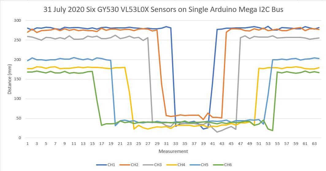
Success! I finally got more than three VL53L0X sensors working on the same I2C bus using an Arduino controller! However, I’m embarrassed to say that in the process, I discovered a hidden broken ground wire in one of my two I2C bus daisy chains, and this may have been causing the symptoms I was seeing with the Teensy 2-bus configuration – don’t know yet.
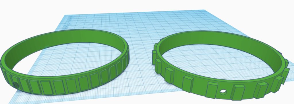
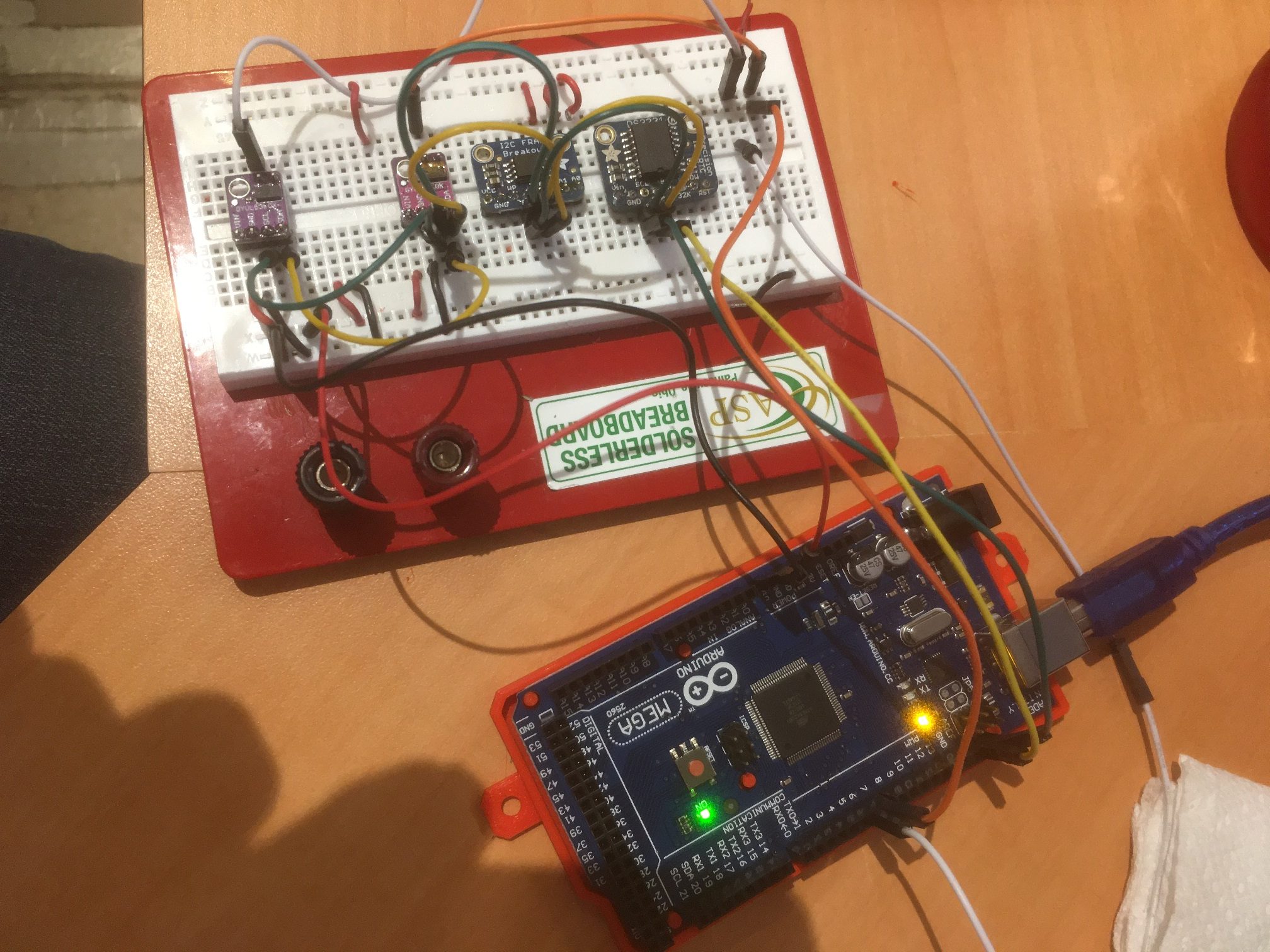
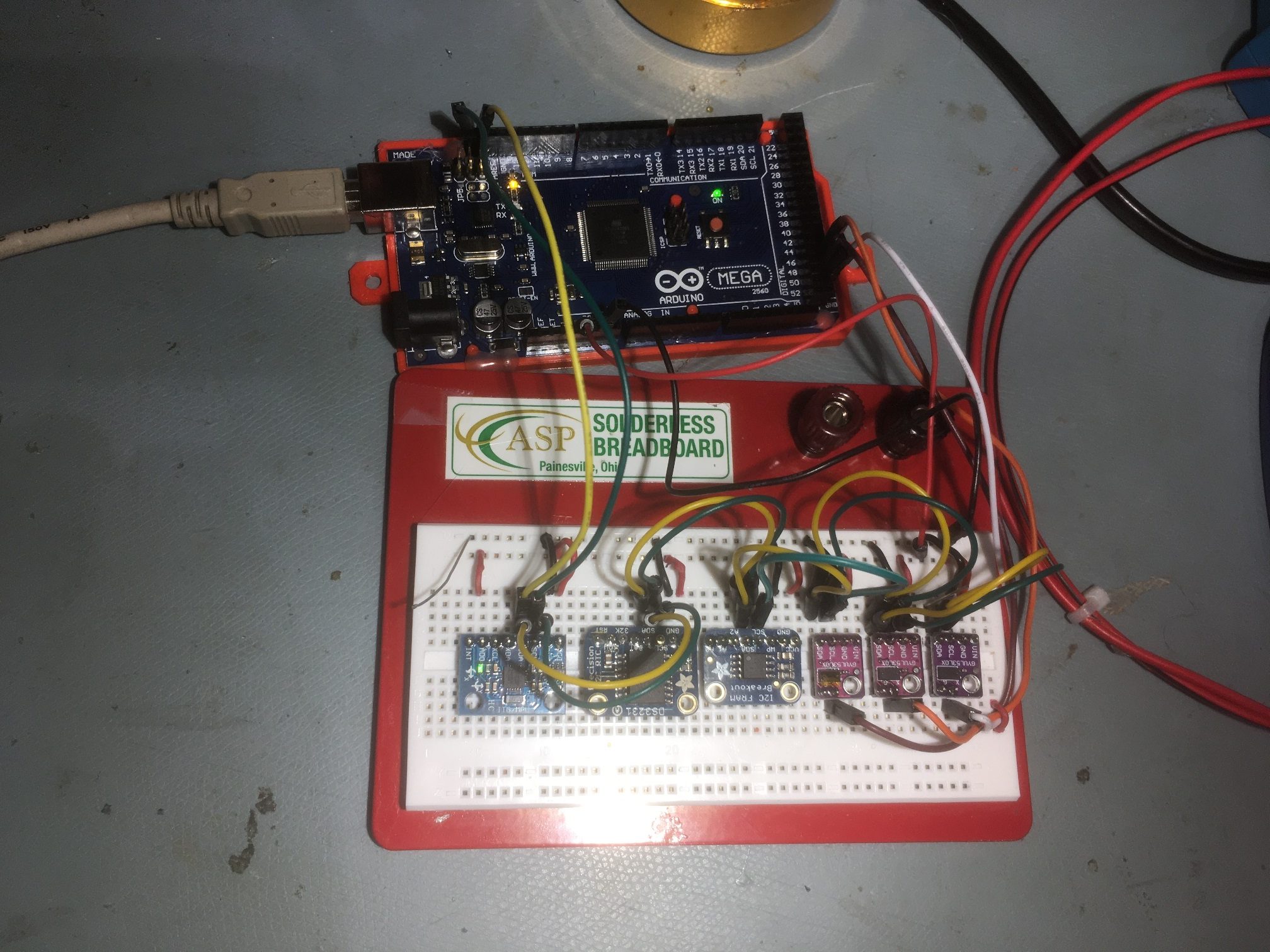
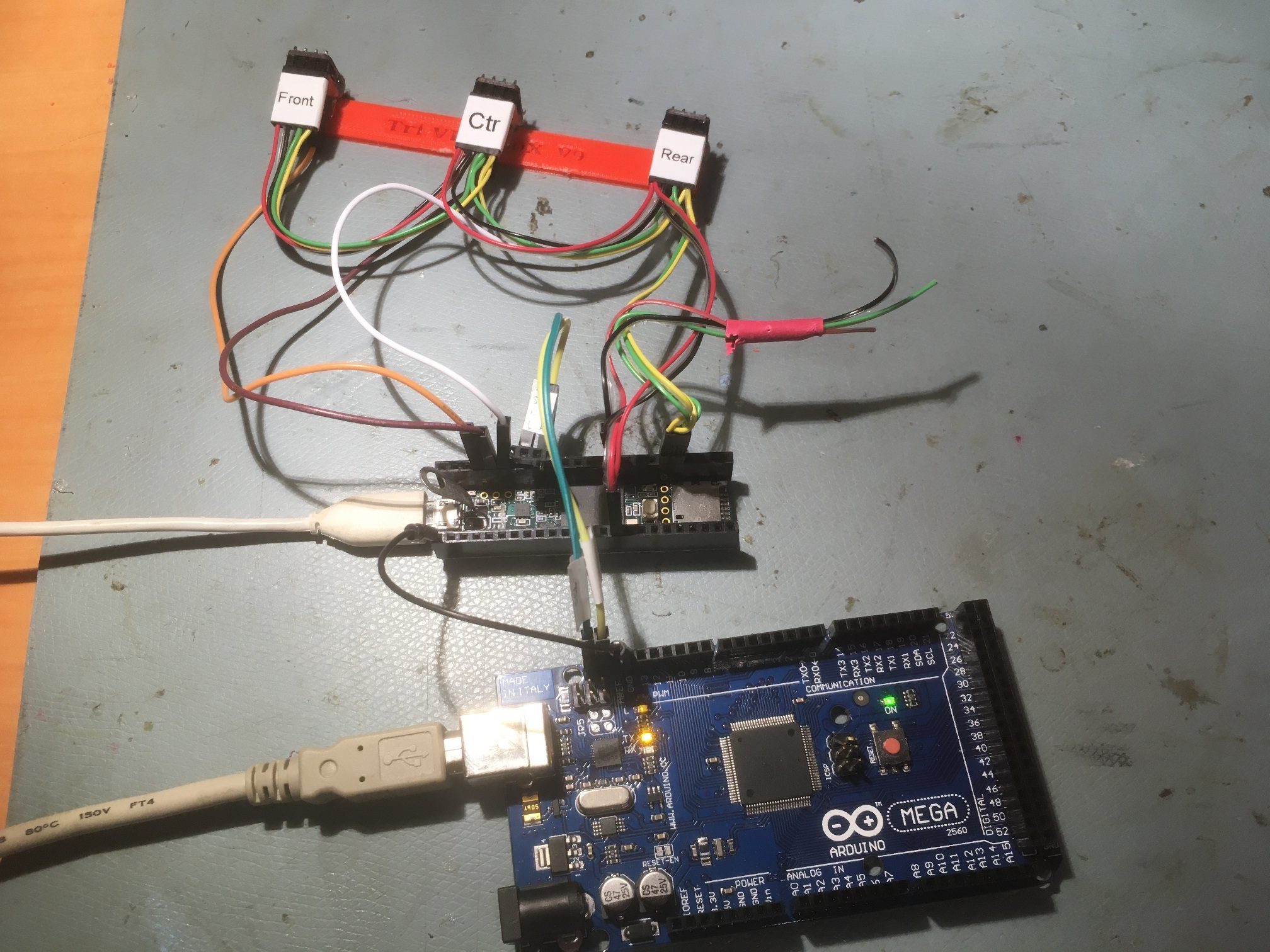
In any case, after repairing the wire break I got a set of six VL53L0X sensors working, consisting of the three Pololu modules I just got in, plus three of the older GY530 modules I was using on earlier Teensy-based experiments. After that, I was able to demonstrate proper operation of the two 3-sensor arrays from my Wall-E2 robot, as shown in the following photo and Excel plot.
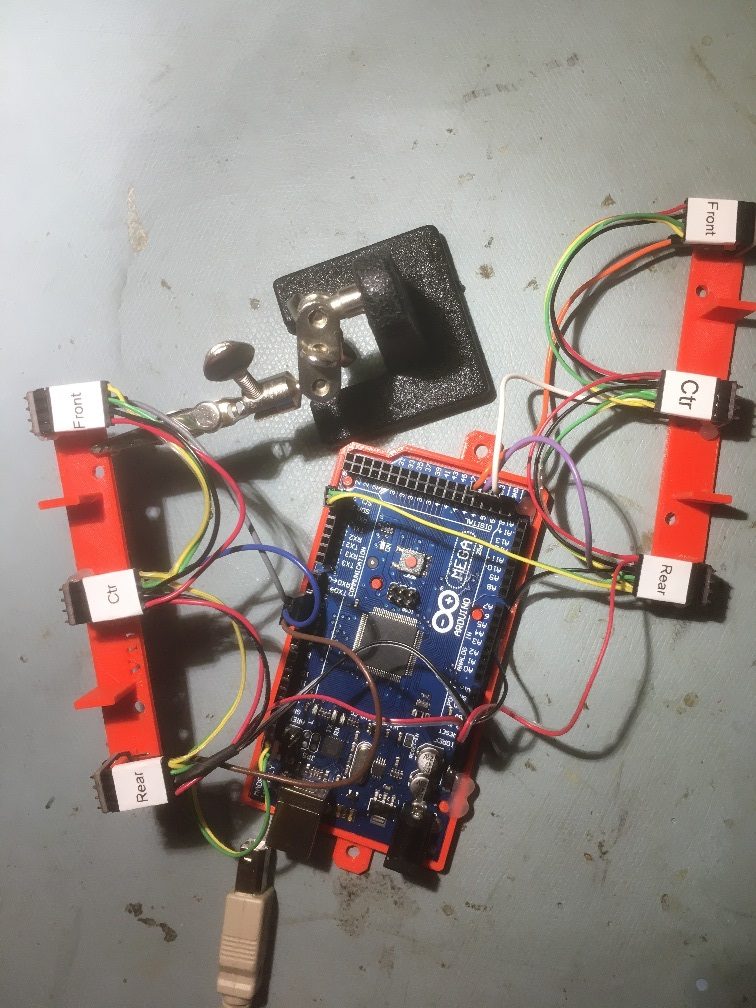
Sensor arrays dismounted from Wall-E2 and connected to Arduino Mega I2C bus
01 August 2020 Update:
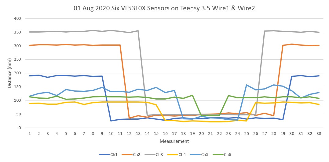
Well, it is officially time to eat crow. After all the whooping and hollering I’ve done, it turns out the entire problem was a hidden ground wire break in I2C daisy-chain cable attached to the Teensy 3.5’s Wire2 I2C bus. After repairing the break, I can now demonstrate operation of six VL53L0X sensors on two different I2C buses on the Teensy 3.5, as shown in photo and Excel plot below.
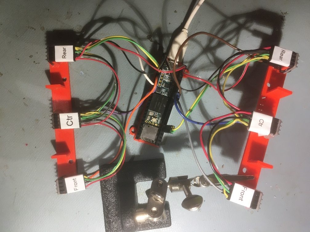
Six VL53L0X sensors on Teensy 3.5 Wire1 & Wire2 I2C buses. Note ground wire repair on left rear connector (top right in photo)
Now that this saga has been thankfully resolved, I can get back to the original project of integrating these two sensor arrays onto Wall-E2, my autonomous wall-following robot.
August 08, 2020 Update:
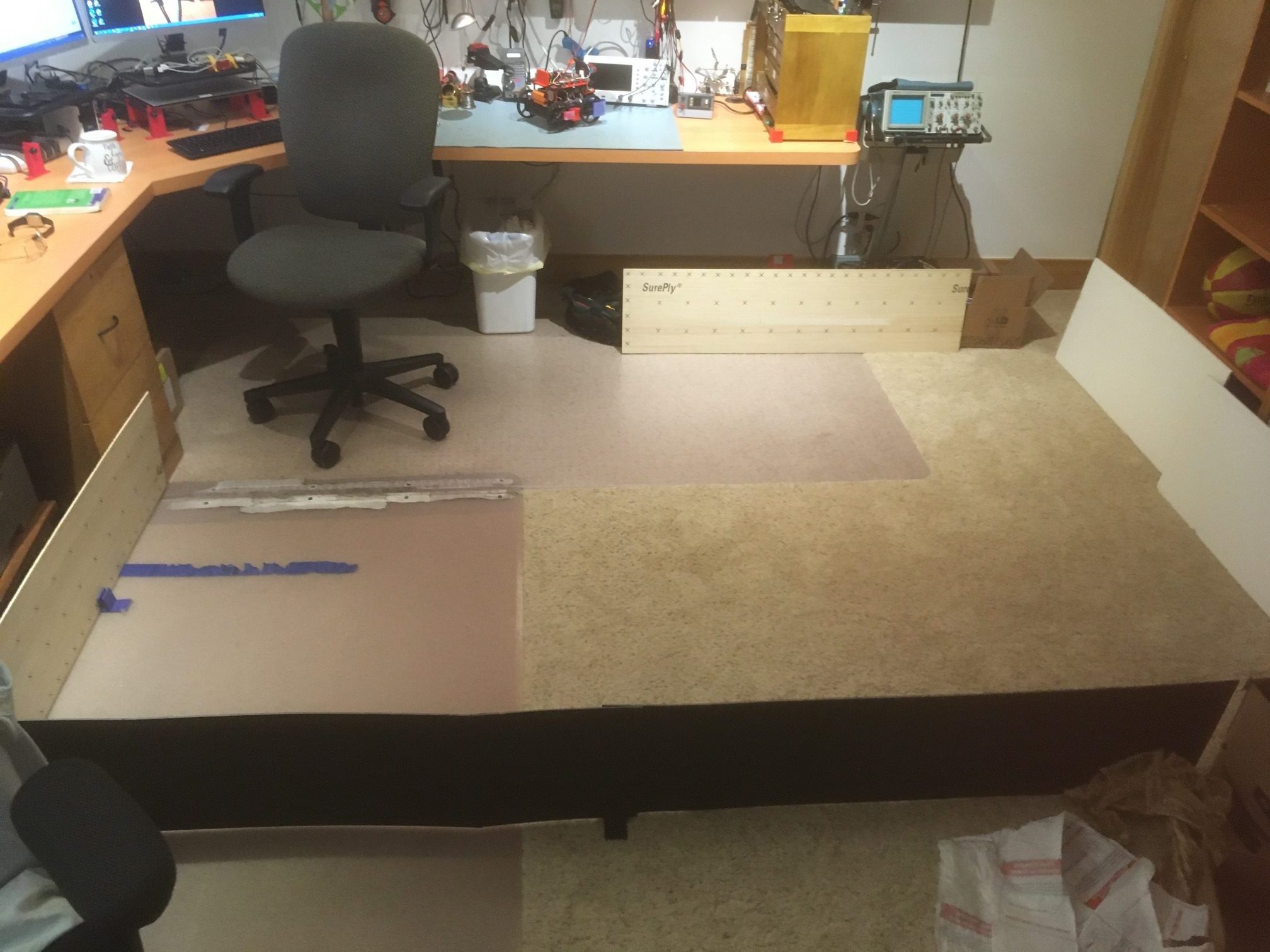
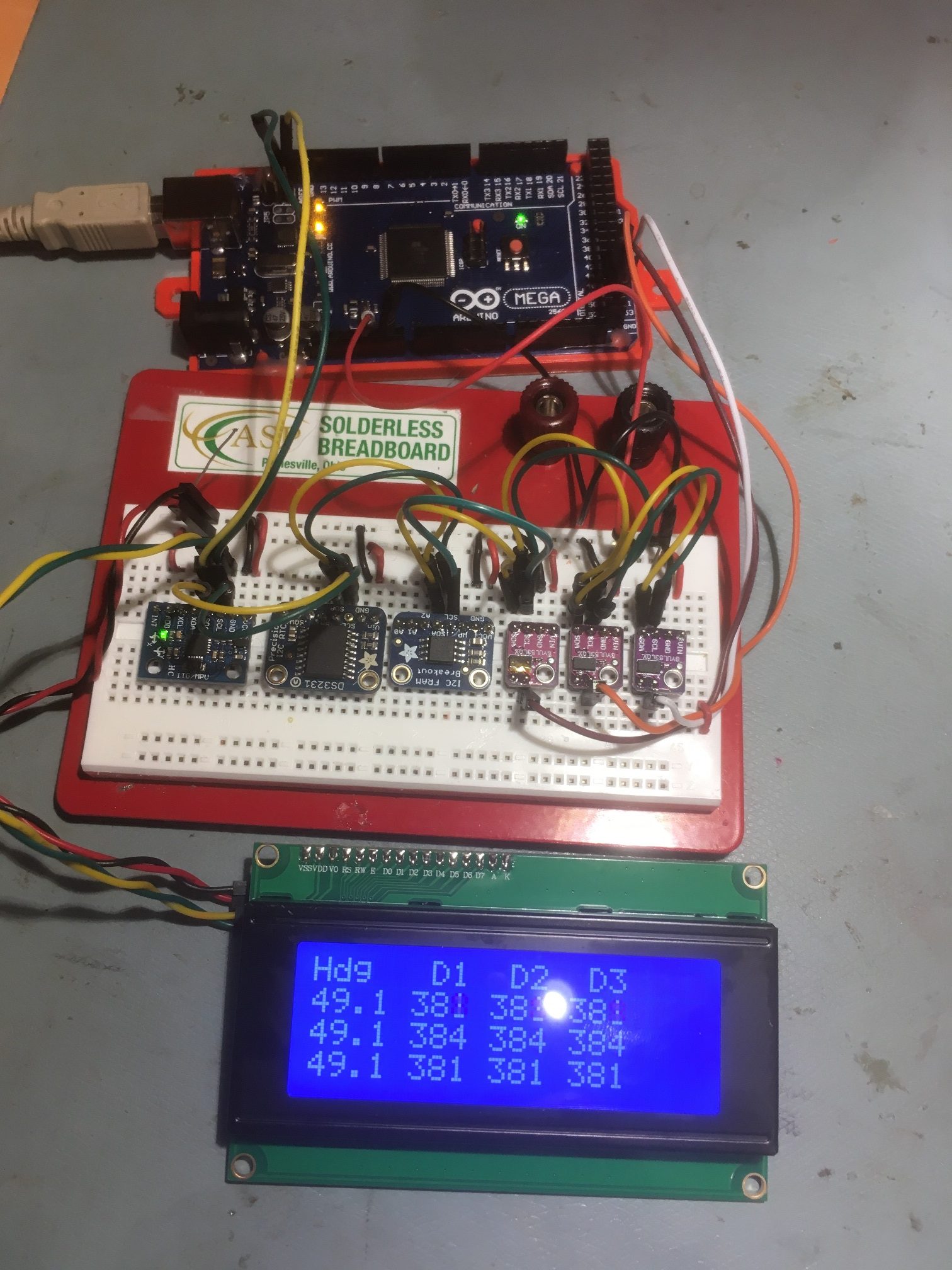
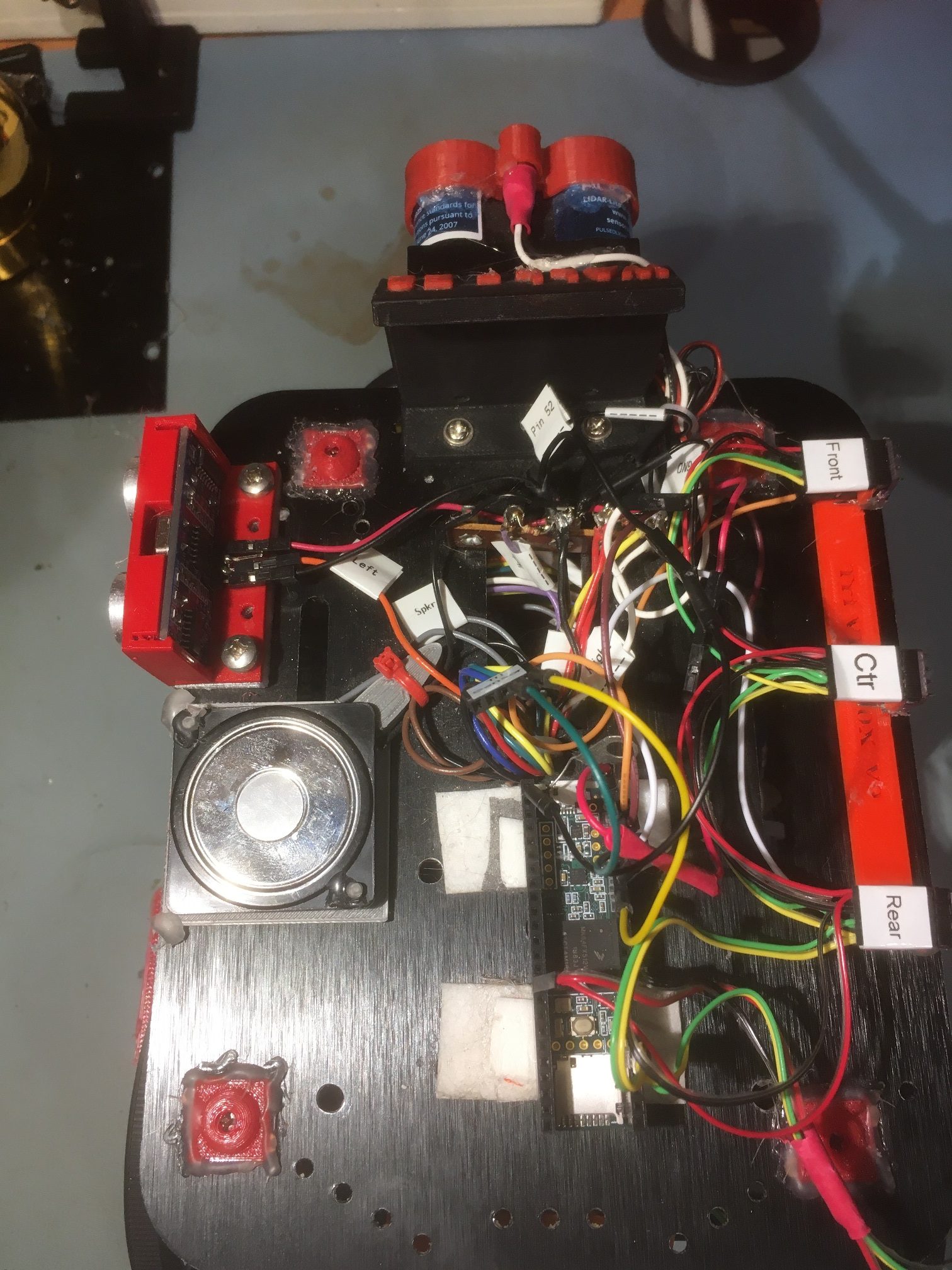
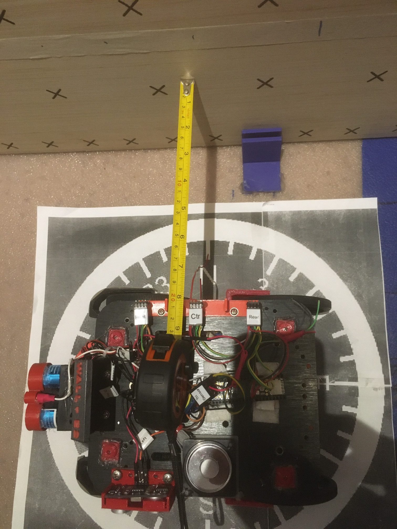
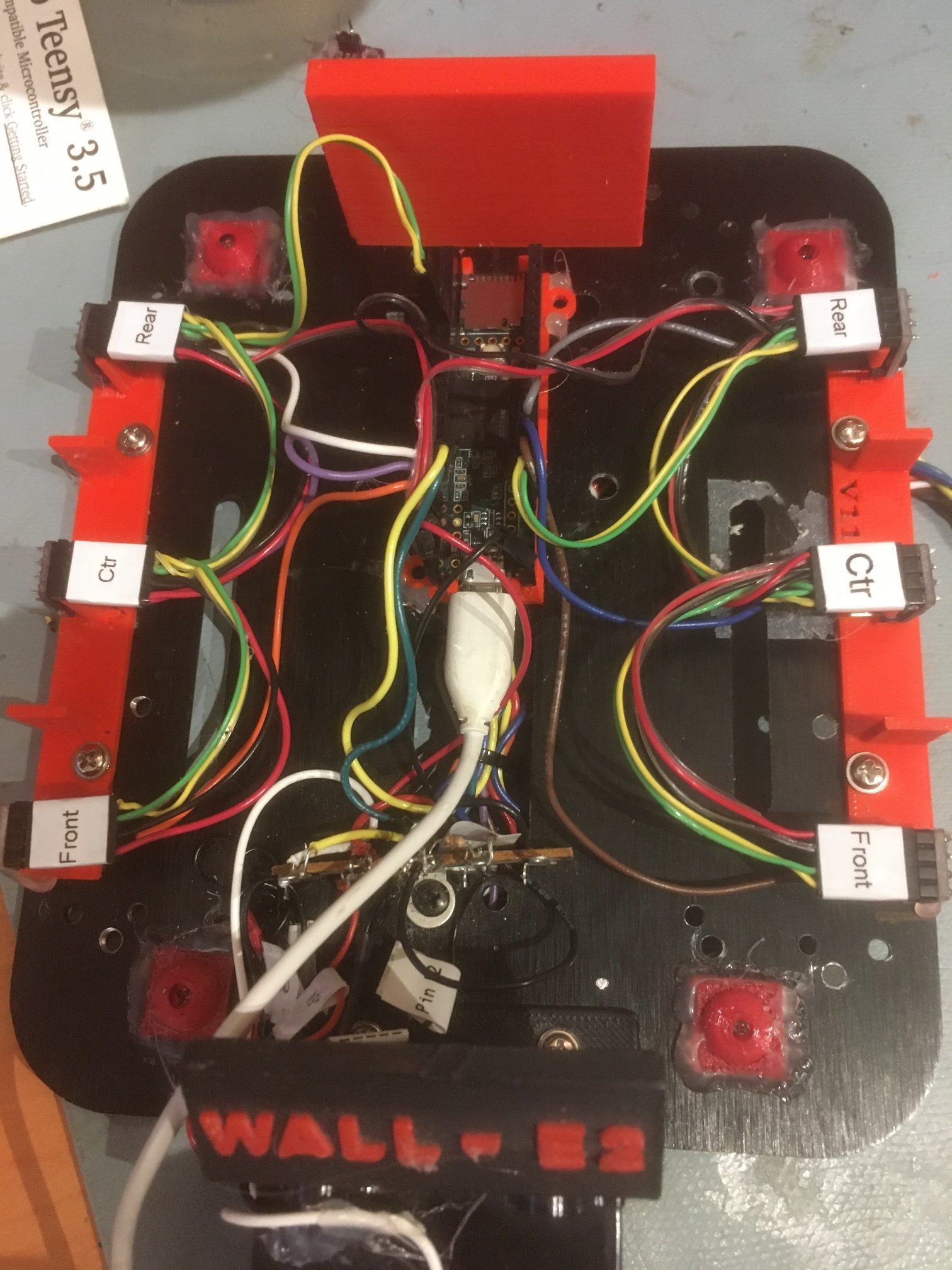
I believe I have finally completed the effort to integrate the VL53L0X sensor arrays onto Wall-E2, my autonomous wall-following robot. Here’s the physical setup
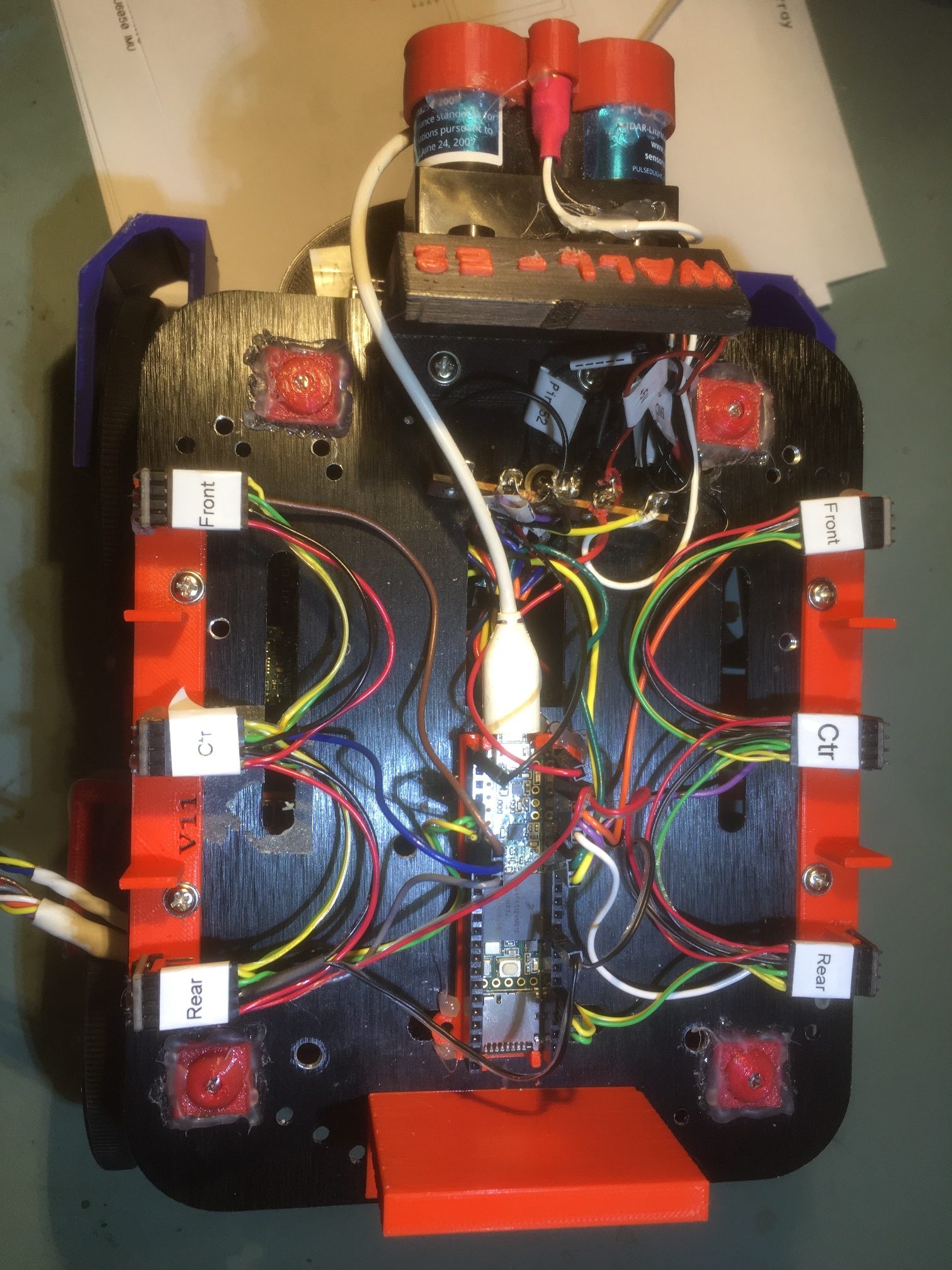
Dual 3-element VL53L0X sensor arrays on top deck of Wall-E2.
Note that the USB cable to the Teensy 3.5 is temporary, just for testing. To verify proper operation, I wrote a small program for the Mega 2560 main controller containing only the code from the main FourWD_WallE2_V5.ino required to retrieve sensor values from the Teensy 3.5, and used this program to verify and debug the Teensy 3.5 program. As the two Excel plots below show, the main Mega 2560 controller can now retrieve distance data from all six VL53L0X sensors at once.
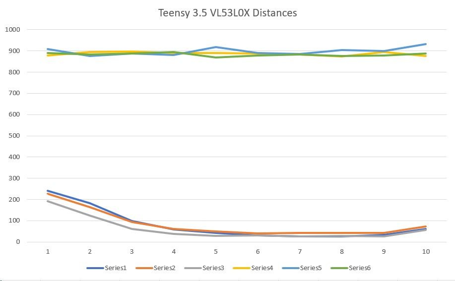
VL53L0X distances reported locally by the Teensy 3.5
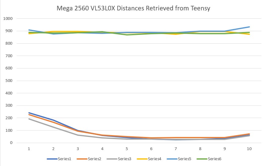
VL53L0X distances as retrieved from the Teensy 3.5 by the Mega 2560
There are some very small differences in these two plots, which I attribute to the fact that the Teensy measurement timing and the Mega 2560 retrieval timing are asynchronous, so the Mega may be retrieving some new and some ‘old’ (in the sense that it might be 100 mSec older than the rest) measurement data. This is insignificant operationally, and wouldn’t be evident unless this sort of simultaneous local/remote reporting was done.
A minor side note; I wound up using the GY530 ‘no name’ sensors rather than the Pololu ones because they were a) smaller, and b) already mounted on the two custom brackets I printed for them. The Pololu sensors (along with a whole bunch of GY530’s that finally arrived from Ali Express) went into my ‘Sensors’ parts bin for the next project. If anyone needs VL53L0X sensors, let me know! 😉
Stay tuned,
Frank