Back to the future with Wall-E2. Wall-following Part IV

Posted 30 April 2019

In two previous posts (here & here) I described my efforts to upgrade Wall-E2’s wall following performance using a PID control algorithm.  The results of my efforts to date in this area have not been very spectacular – a better description might actually be ‘dreadful’ :-(.

After some additional analysis, I came to believe that the reason the PID approach doesn’t work very well is a fundamental feature of the way Wall-E2 measures distance to the nearest wall.  Wall-E2 has two acoustic sonar units fixed to its upper deck, and they measure the distance perpendicular to the robot’s longitudinal axis.  What this means, however, is that when the robot is angled with respect to the nearest wall, the distance measured isn’t the perpendicular distance, but rather the hypotenuse of the right triangle with the right angle at the wall.  So, when Wall-E2 turns toward or away from the wall, the measured distance increases even though the robot hasn’t actually moved toward or away.  Conversely, if the robot is angled in toward the wall and then turns to be parallel, the measured distance decreases even if the robot hasn’t moved at all relative to that wall. The situation is shown in the sketch below:

Using Excel, I ran a simulation of the ping distance versus the actual distance for a range of angle offsets from 0 to 30 degrees, as shown below:

As shown above, the ping distance for a constant 25 cm offset ranges from 25 (robot longitudinal axis parallel to the wall) to almost 29 cm for a 30 degree off-axis heading. These values translate to a percentage error of zero to approximately 15%, independent of the initial parallel distance.

So, it becomes obvious why a standard PID algorithm has trouble; if the ping distance goes up slightly, the PID algorithm attempts to compensate by turning toward the wall.  However, this causes the ping distance to increase rather than decrease, causing the algorithm to command an even greater angle toward the wall, which in turn causes a further increase in ping distance – entirely backward.  The reverse happens for an initial decrease in the ping distance starting from a parallel orientation.  The algorithm commands a turn away from the wall, which causes the ping distance to increase immediately, even though the actual distance hasn’t changed.  This causes the algorithm to seriously overcorrect in one case, and seriously undercorrect in the other.   Not good.

What I need is a way to compensate for the changes in ping distance caused by Wall-E2’s angular orientation with respect to the wall being tracked. If Wall-E2 is oriented parallel to the wall, then no correction is needed; if not,then a correction is required.  Fortunately for the good guys, Wall-E2 now has a way of providing the needed heading information, with the integration of the MPU6050-based 6DOF IMU module described in this post from last September.

To investigate this idea, I modified an old test program to have Wall-E2 perform a series of mild S-turns in my test hallway while capturing heading and ping distance data.  The S-turns were tweaked so that Wall-E2 stayed a fairly constant 50 cm from the right-hand wall, as shown in the following movie clip.


Start of test area showing tape measure for offset distance measurement

Using Excel, I plotted the reported ping distance, the commanded heading, and the actual heading versus time, as shown below:

In the above plot, the initial CCW turn (away from the wall) was a 10° change, and all the rest were approximately 20° to maintain a more-or-less straight line.  At the end of the second (the first CW turn) and subsequent heading changes, there is an approximately 0.5 sec straight period, during which no data was captured.  As can be seen, the ping distance (gray curve) goes up slightly as the first CCW turn starts, then levels off during the changeover from CCW to CW turns, and then precipitously declines as the CW turn sweeps the ping sensor toward the perpendicular point.  Part of this decline is actual distance change caused by the 0.5 sec straight period that moves the robot toward the wall.  After the next (CCW) heading change is commanded, the robot starts to turn away from the wall causing the ping distance to increase, but this is partially cancelled by the fact that the robot continues to travel toward the wall during the S-turn. As soon as the robot gets parallel to the wall, then the ping distance goes up quickly as the heading continues to change in a CCW direction.  This behavior repeats for each S-turn until the end of the run.

As an exercise, I added another column to the spreadsheet – “perpendicular distance”, and set up a formula to compute the adjusted distance from the robot to the wall, using the recorded angular offset.  This computation presumes that the robot started off parallel to the wall (confirmed via the video clip).  The result is shown on the yellow line in the plot below:

Ping distance and heading vs time, with calculated perpendicular distance added


As can be seen from the above plot and video, the compensated distance looks like it might be a good match with the perpendicular distance estimated from the video. For instance, at 17 sec into the video, the robot has just finished the first clockwise turn and straight run, and is just starting the second counter-clockwise turn.  At this point the robot is oriented parallel to the wall, and the ping distance and the perpendicular distance should match. The video shows that distance should be about 33-35 cm, and the recorded ping distance at this point is 36 cm.  However, the calculated distance went directly from 45 cm at point 11 to 34 cm at point 12 and basically stayed at that value before changing rapidly from 34 to 45 over points 19 & 20.  Again at 19 seconds into the video, the robot is approximately 42-44 cm from the wall and parallel to it; both the actual ping distance and the calculated perpendicular distance agree at this point at 45 cm – a close match to the estimate from the video.

So now the question is – can I use the calculated perpendicular wall distance to assist wall-following operations?  A significant issue may be knowing when the robot is actually parallel to the wall, to establish a heading baseline for compensation calcs.

When is the robot parallel to the wall?

A unique feature of the point or points where the robot is parallel to the wall is that the ping distance and the calculated distance are equal.  However, that’s a bit of ‘chicken and the egg’ as one has to know the robot is parallel in order to use an offset angle of 0 degrees for the compensation calc to work out.  Since the heading information available from the MPU6050 IMU is only relative, the heading value for the parallel condition can be anything, and can vary arbitrarily from run to run.  So, what to do?  One thought would be to have the robot make a short S-turn at the start of any tracking run to establish the heading for which the ping distance goes through a minimum or maximum – the heading for the max/min point would be the parallel heading. From there on, that heading should be reliably constant until the next time the robot’s power is cycled.  Of course, a new parallel heading value would be required each and every time Wall-E2’s tracking situation changes (obstacle recovery, step-turns and reversals at the end of a hallway, changing from the left wall to the right one, etc).  Maybe a hybrid mode would be feasible, whereby the robot uses uncompensated heading-based S-turns instead of the current ‘bang-bang’ system for initial wall tracking, shifting to a compensation algorithm after a suitable parallel heading is determined.

Looking at the above plots, it may not be all that useful to look for maxima and/or minima, as there are multiple headings for which the ping distance is constant, so which one is the parallel heading?  Thinking about ways to rapidly find the parallel heading, it occurred to me that my previous work on quickly finding the mathematical variance of a set of values might be useful here.  I plugged the above ping distance numbers into the Excel spreadsheet I used before, and got the following plot of ping distance and 3-element running variance vs time.

So, looking at the above plot, it is encouraging that a 3-point running variance calculation shows near-zero values when the robot is most probably parallel or nearly parallel to the wall.  Adding the heading information to the spreadsheet gives the plot shown below

and now it is clear that the large variance values are associated with the changes from one heading to another, and the low variance values are associated with the middle section of each linear heading change (S-turn) segment.  If I further enhance the plot by putting the variance plot on a secondary scale and zooming in on the low variance sections, we get the plot shown below:


Variance scale modified to show 0-5 range only

In the above plot, the variance line is zoomed in to the 0-5 range only, emphasizing the 0-0.5 unit variance range.  In this plot it can be seen that the variance actually has a distinct minimum very near zero at time points 7, 16, 22, 28-30, and 35-38.  These time values correspond to robot heading values of 64, 61, 63, 61-67. and 70-65.  Discarding the last set as bad data (this is where the robot literally ‘hit the wall’ at the end of the run), we can compute an approximate parallel heading value as the average of all these values, or the average of 64, 61, 63, 64 (average of 61-67) = 63 degrees.  From the video we can see that the robot started out parallel to the wall, and the first heading reading was 62 degrees – a very good match to the calculated parallel heading value.

The next step, I think, is to run some more field tests against a wall, with wall-following and heading assist integrated into the code.

Frank


MPU6050 IMU Motor Noise Troubleshooting

Posted 24 July 2019

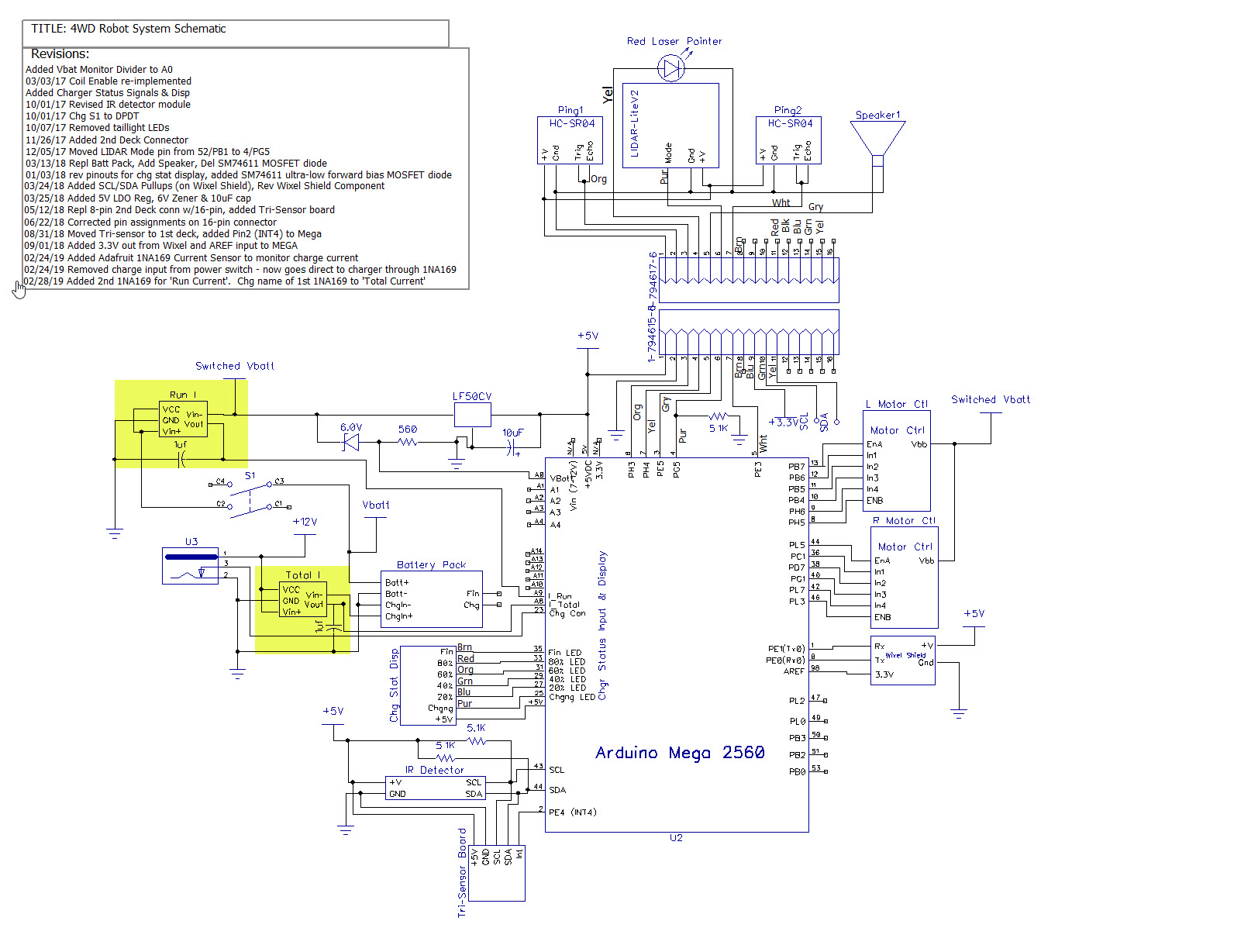
For a while now I’ve been investigating ways of improving the wall following performance of my autonomous wall-following robot Wall-E2.  At the heart of the plan is the use of a MPU6050 IMU to sense relative angle changes of the robot so that changes in the distance to the nearest wall due only to the angle change itself can be compensated out, leaving only the actual offset distance to be used for tracking.

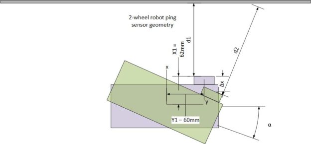
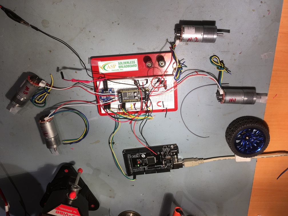
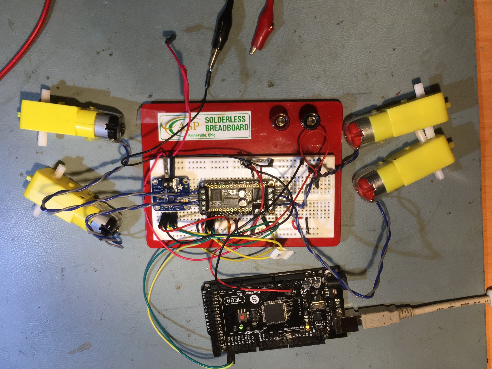
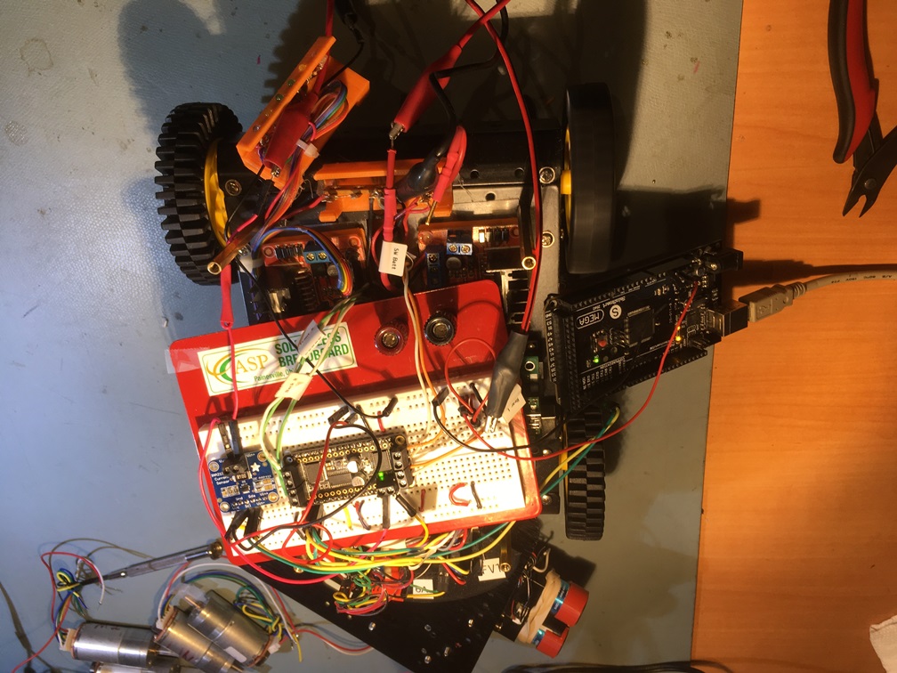
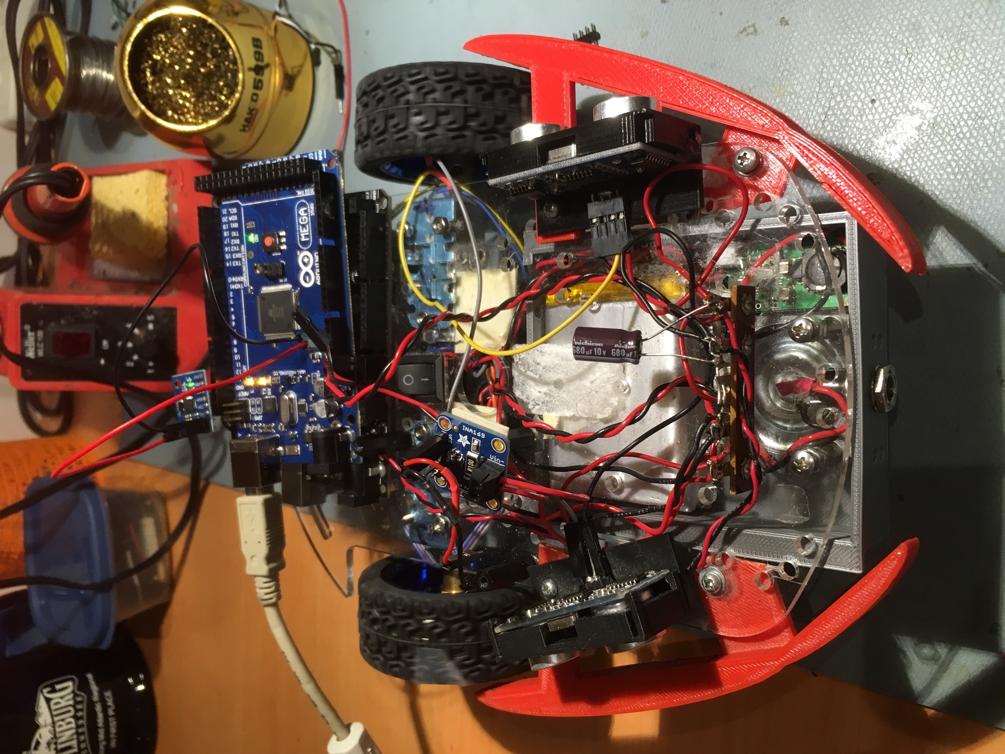
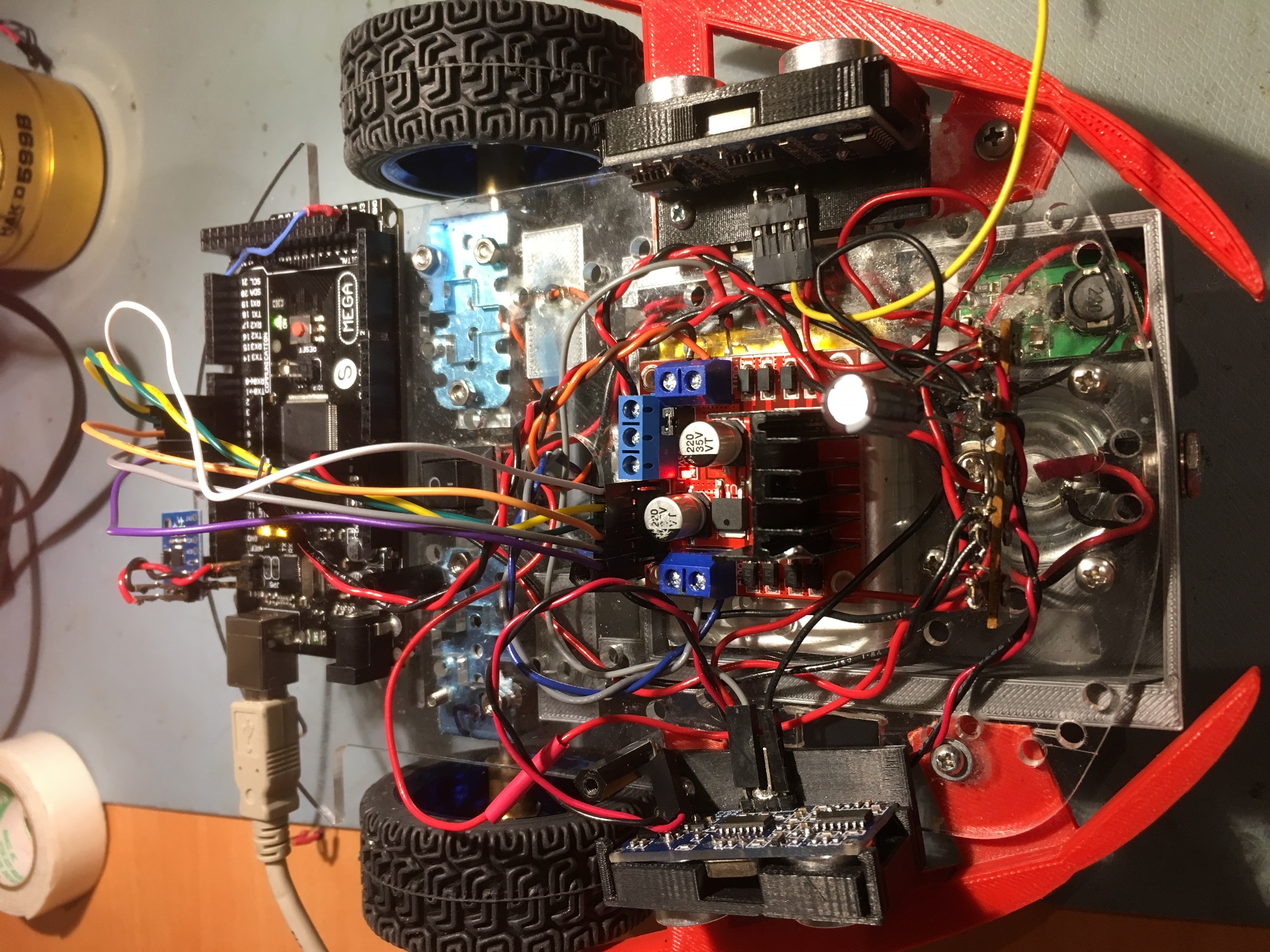
As the test vehicle for this project, I am using my old 2-motor robot, fitted with new Pololu 125:1 metal-geared DC motors and Adafruit DRV8871 motor drivers, as shown in the photo below.

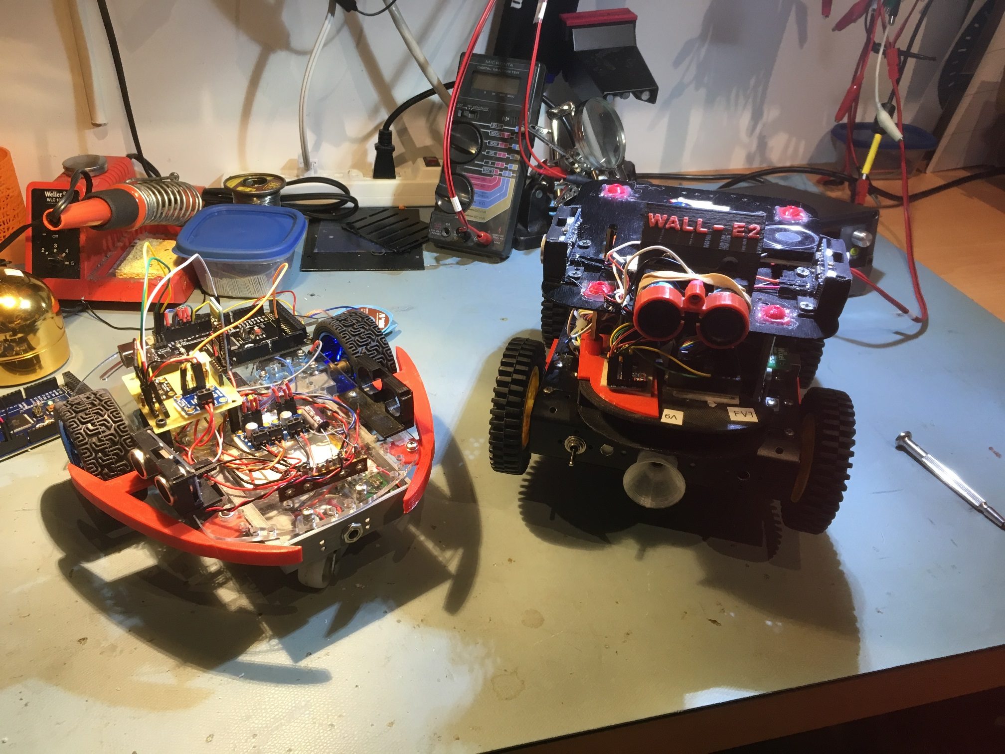
2-motor test vehicle on left, Wall-E2 on right

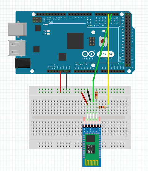
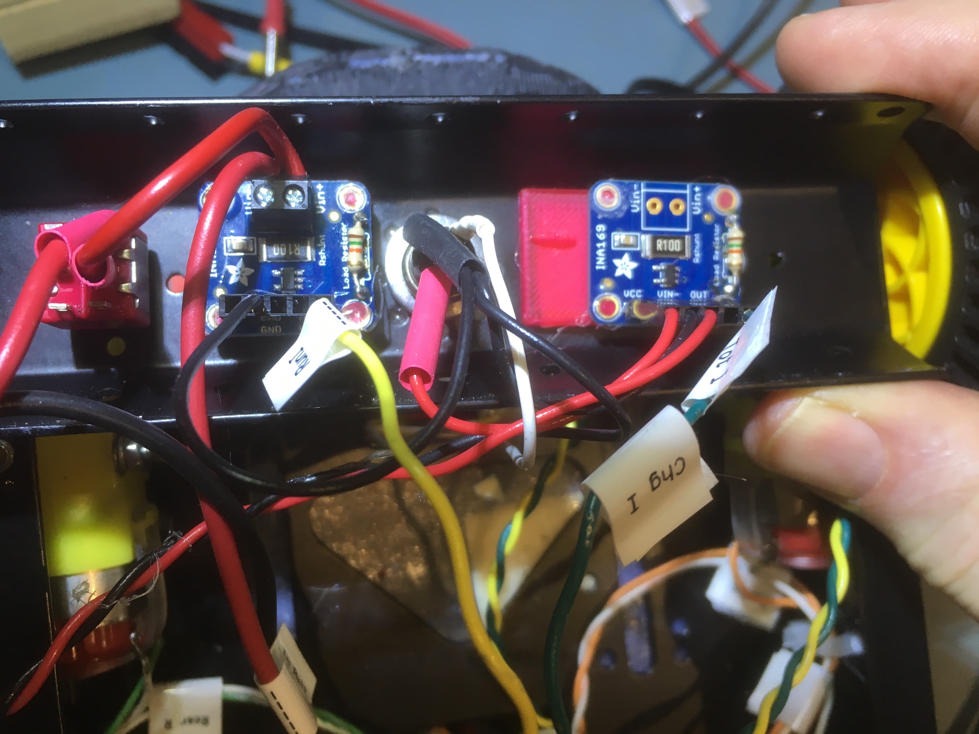
The DFRobots MPU6050 IMU module is mounted on the green perfboard assembly near the right wheel of the 2-motor test robot, along with an Adafruit INA169 high-side current sensor and an HC-05 Bluetooth module used for remote programming and telemetry.

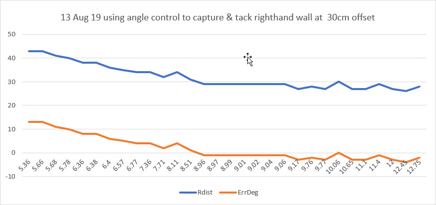
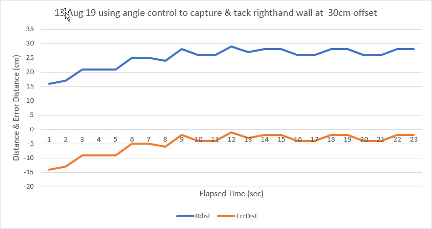
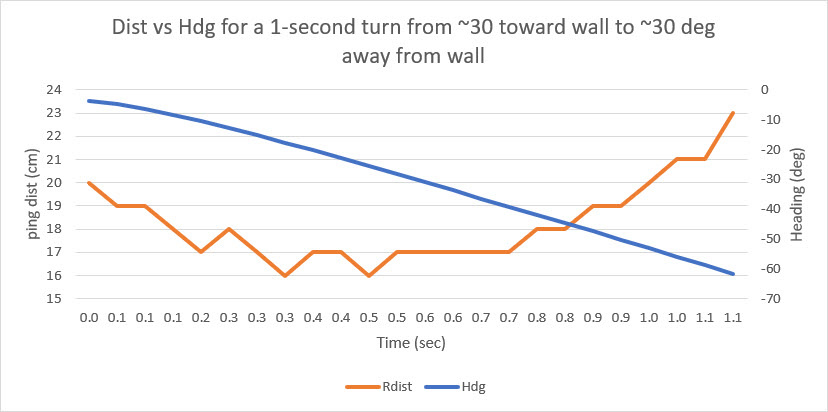
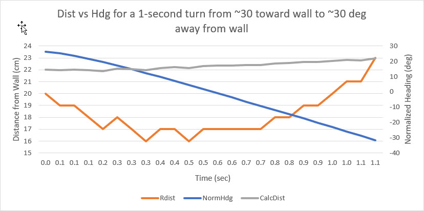
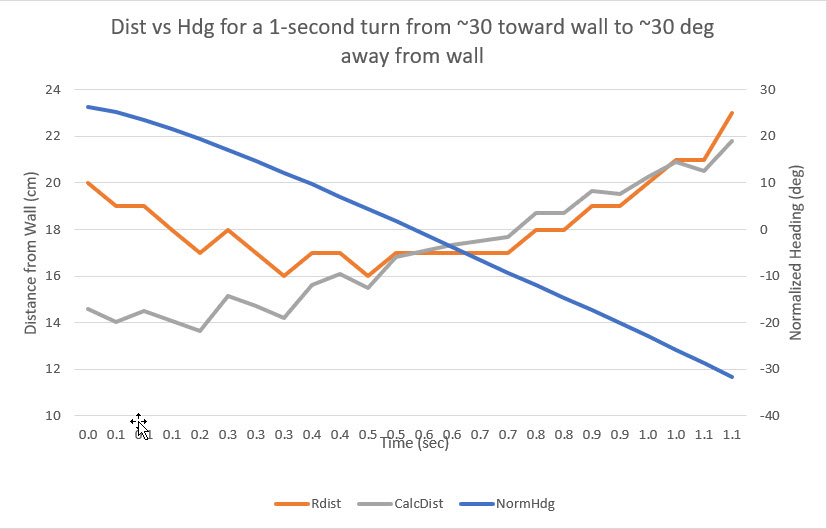
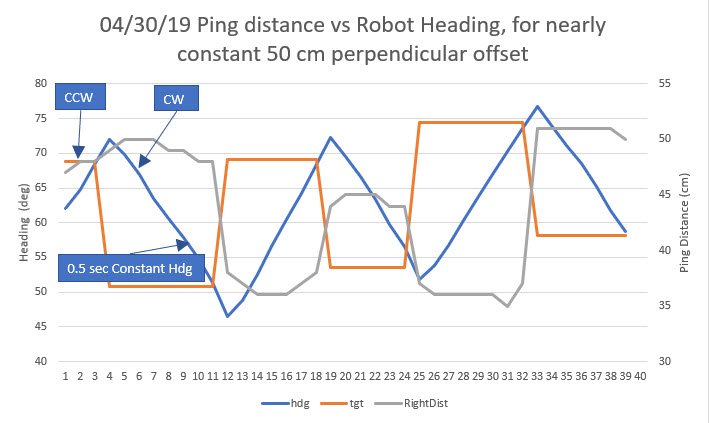
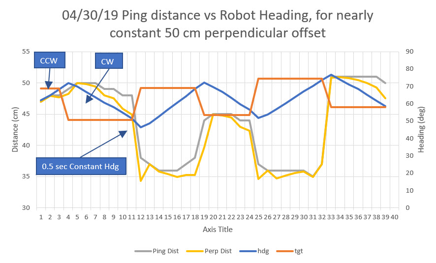
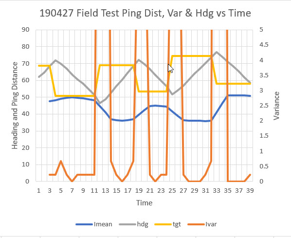
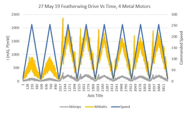
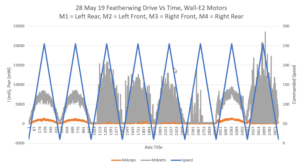
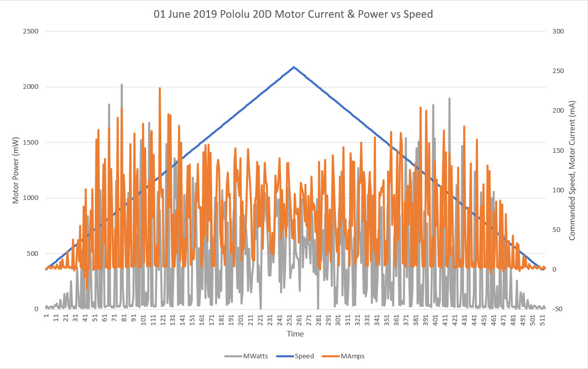
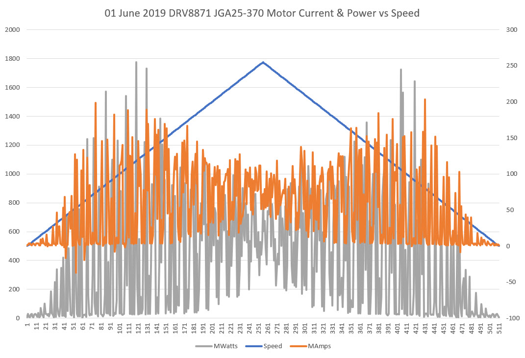
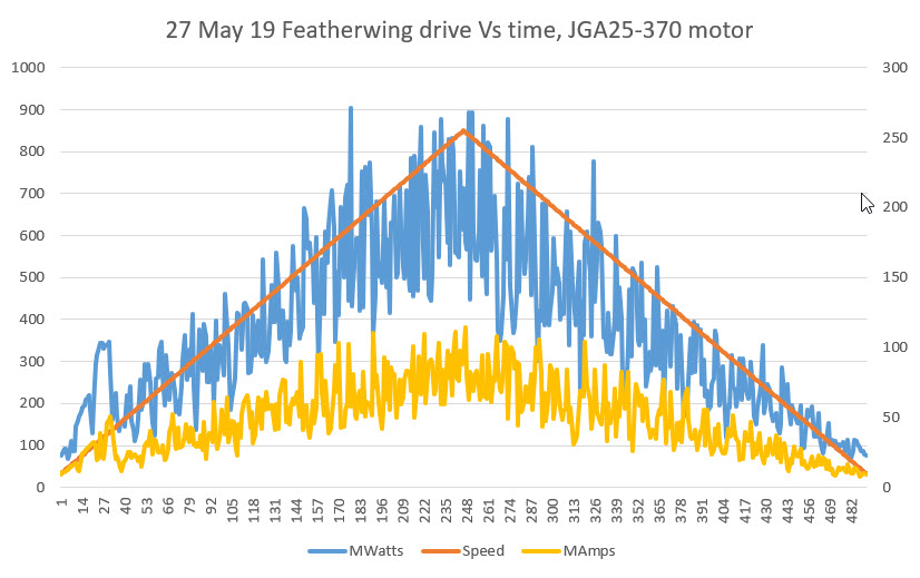
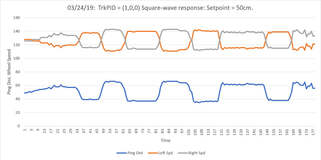
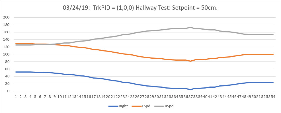
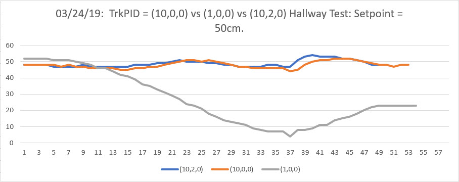
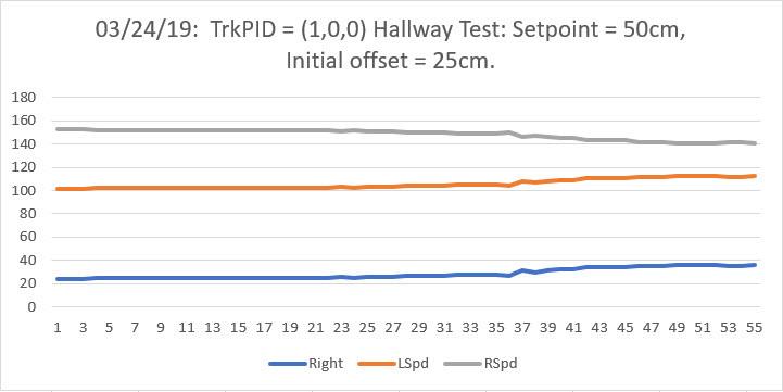
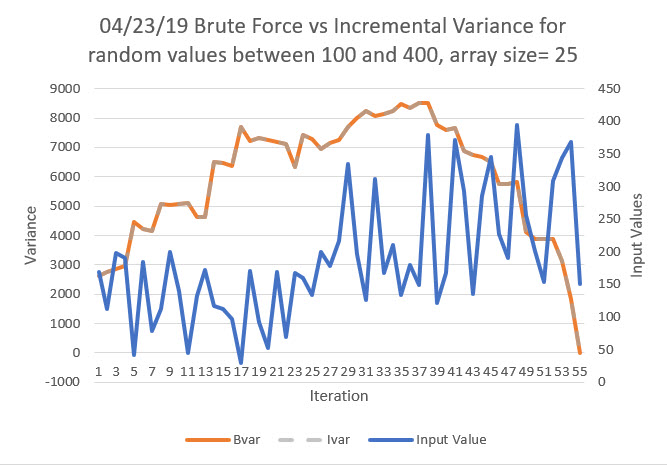
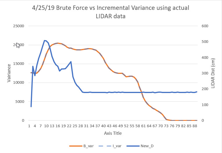
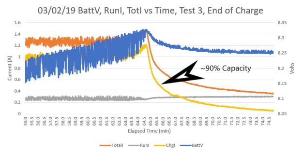
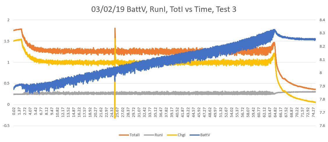
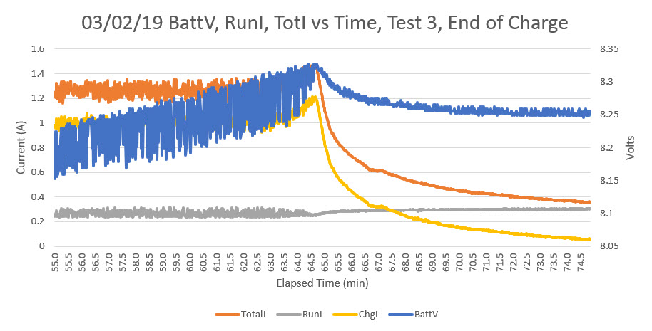
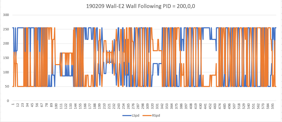
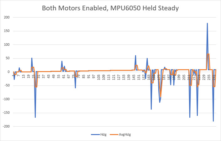
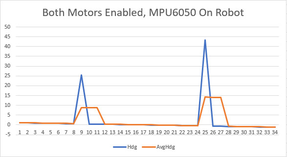
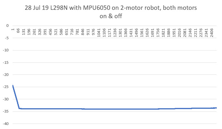
This worked great at first, but then I started experiencing anomalous behavior where the robot would lose track of the relative heading and start turning in circles.  After some additional testing, I determined that this problem only occurred when the motors were running.  It would work fine as long as the motors weren’t running, but since the robot had to move to do its job, not having the ability to run the motors was a real ‘buzz-kill’.  I ran some experiments on the bench to demonstrate the problem, as shown in the Excel plots below:

Troubleshooting:

There were a number of possibilities for the observed behavior:

  1. The extra computing load required to run the motors was causing heading sensor readings to get missed (not likely, but…)
  2. Motor noise of some sort was feeding back into the power & ground lines
  3. RFI created by the motors was getting into the MPU6050 interrupt line to the Arduino Mega and causing interrupt processing to overwhelm the Mega
  4. RFI created by the motors was interfering with I2C communications between the Mega and the MPU6050
  5. Something else

Extra Computing Load:

This one was pretty easy to eliminate.  The main loop does nothing most of the time, and only updates system parameters every 200 mSec.  If the extra computing load was the problem, I would expect to see no ‘dead time’ between adjacent adjustment function blocks.  I had some debug printing code in the program that displayed the result of the ‘millis()’ function at various points in the program, and it was clear that there was still plenty of ‘dead time’ between each 200 mSec adjustment interval.

Motor noise feeding back into power/ground:

I poked around on the power lines with my O’scope with the motors running and not running, but didn’t find anything spectacular; there was definitely some noise, but IMHO not enough to cause the problems I was seeing.  So, in an effort to completely eliminate this possibility, I removed the perfboard sub-module from the robot entirely, and connected it to a separate Mega microcontroller. Since this setup used completely different power circuits (the onboard battery for the robot, PC USB cable for the second Mega), power line feedback could not possibly be a factor.  With this setup I was able to demonstrate that the MPU6050 output was accurate and reasonable until I placed the perfboard sub-module in close proximity to the robot; then it started acting up just as it did when mounted on the robot.

So it was clear that the interference is RFI, not conducted through any wiring.

RFI created by the motors was getting into the MPU6050 interrupt line to the Arduino Mega and causing interrupt processing to overwhelm the Mega

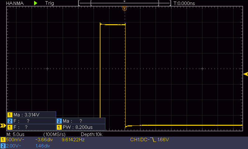
This one seemed very possible.  The MPU6050 generates interrupts at a 20Hz rate, but I only use measurements at a 5Hz (200mSec) rate.  Each interrupt causes the Interrupt Service Routine (ISR) to fire, but the actual heading measurement only occurs every 200 mSec. I reasoned that if motor-generated RFI was causing the issue, I should see many more activations of the ISR than could be explained by the 20Hz MPU6050 interrupt generation rate.  To test this theory, I placed code in the ISR that pulsed a digital output pin, and then monitored this pin with my O’scope.  When I did this, I saw many extra ISR activations, and was convinced I had found the problem.  In the following short video clip, the top trace is the normal interrupt line pulse frequency, and the bottom trace is the ISR-generated pulse train.  In normal operation, these two traces would be identical, but as can be seen, many extra ISR activations are occurring when the motors are running.

So now I had to figure out what to do with this information.  After Googling around for a while, I ran across some posts that described using the MPU6050/DMP setup without using the interrupt output line from the module; instead, the MPU6050 was polled whenever a new reading was required.  As long as this polling takes place at a rate greater than the normal DMP measurement frequency, the DMP’s internal FIFO shouldn’t overflow.  If the polling rate is less than the normal rate, then FIFO management is required.  After thinking about this for a while, I realized I could easily poll the MPU/DMP at a higher rate than the configured 20Hz rate by simply polling it each time through the main loop – not waiting for the 200mSec/5Hz motor speed adjustment interval.  I would simply poll the MPU/DMP as fast as possible, and whenever new data was ready I would pull it off the FIFO and put it into a global variable.  The next time the motor adjustment function ran, it would use the latest relative heading value and everyone would be happy.

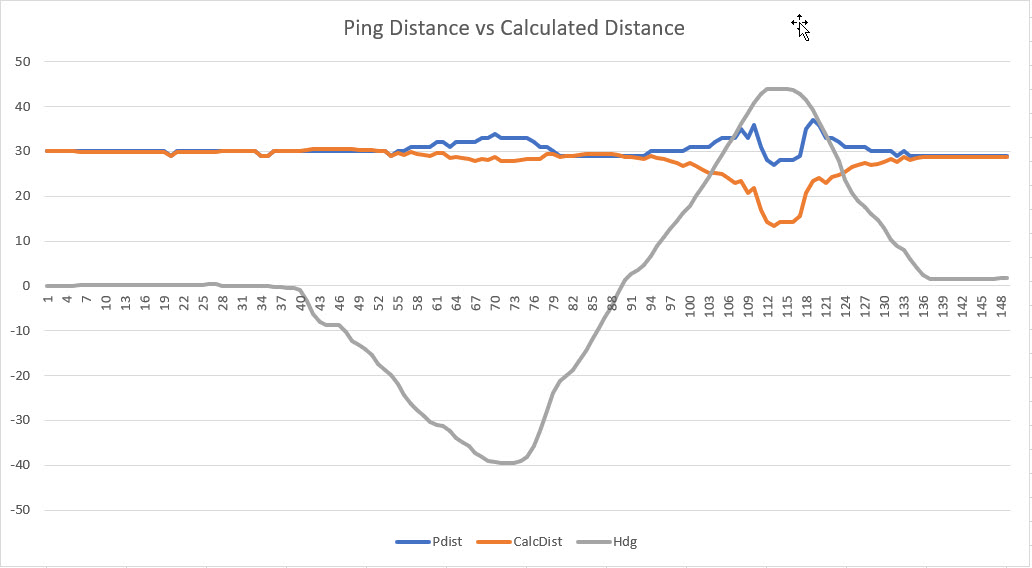
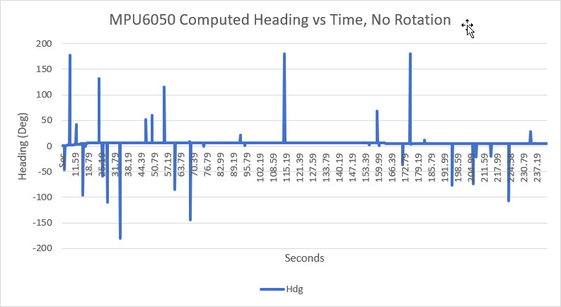
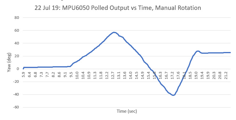
So, I implemented this change and tested it off the robot, and everything worked OK, as shown in the following Excel plot.

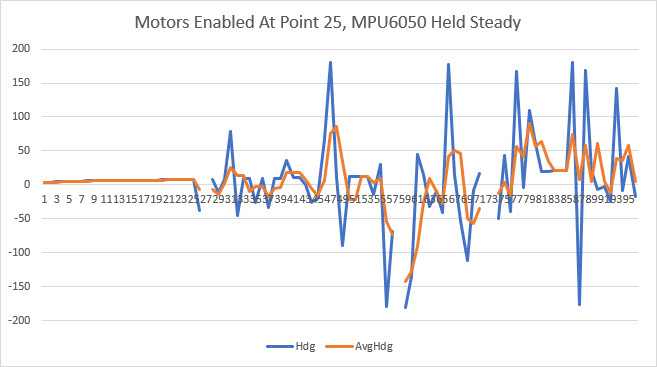
And then I put it on the robot and ran the motors

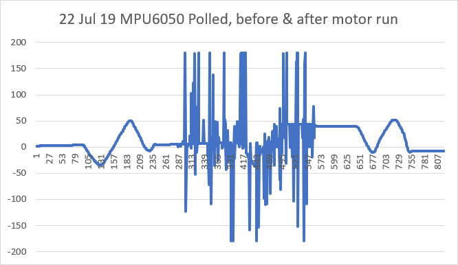
Crap!  I was back to the same problem!  So, although I had found evidence that the motor RFI was causing additional ISP activations, that clearly wasn’t the entire problem, as the polling method completely eliminates the ISP.

RFI created by the motors was interfering with I2C communications between the Mega and the MPU6050

I knew that the I2C control channel could experience corruption due to noise, especially with ‘weak’ pullup resistor values and long wire runs.  However, I was using short (15cm) runs and 2.2K pullups on the MPU6050 end of the run, so I didn’t think that was an issue.  However, since I now knew that the problem wasn’t related to wiring issues or ISR overload, this was the next item on the list.  So, I shortened the I2C runs from 15cm to about 3cm, and found that this did indeed suppress (but not eliminate) the interference.  However, even with this modification and with the MPU6050 module located as far away from the motors as possible, the interference was still present.

Something else

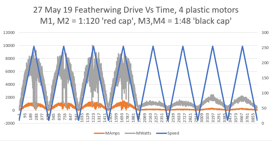
So, now I was down to the ‘something else’ item on my list, having run out of ideas for suppressing the interference.  After letting this sit for a few days, I realized that I didn’t have this problem (or at least didn’t notice it) on my 4-motor Wall-E2 robot, so I started wondering about the differences between the two robot configurations.

  1. Wall-E2 uses plastic-geared 120:1 ‘red cap’ motors, while the 2-motor robot uses pololu 125:1 metal-geared motors
  2. Wall-E2 uses L298N linear drivers while the 2-motor version uses the Adafruit DRV8871 switching drivers.

So, I decided to see if I could isolate these two factors and see if it was the motors, or the drivers (or both/neither?) responsible for the interference. To do this, I used my new DPS5005 power supply to generate a 6V DC source, and connected the power supply directly to the motors, bypassing the drivers entirely.  When I did this, all the interference went away!  The motors aren’t causing the interference – it’s the drivers!

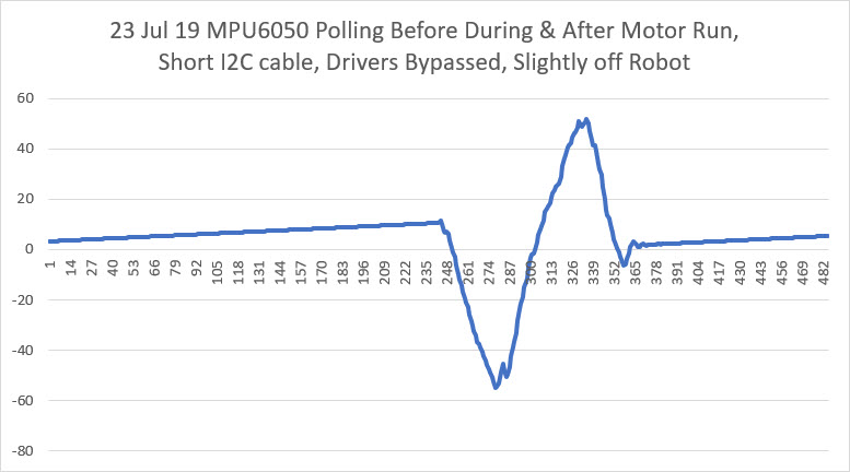
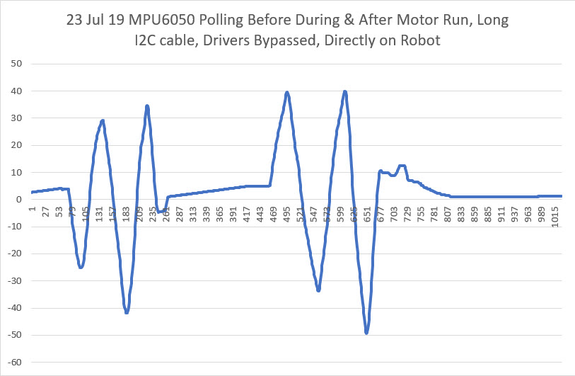
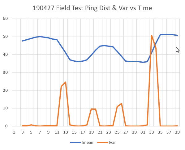
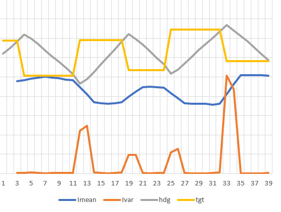
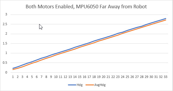
In the first plot above, I used a short (3cm) I2C wire pair and the module was located near, but not on, the robot. As can be seen, no interference occurred when the motors were run.  In the second plot I used a long (15cm) I2C wire pair and mounted the module directly on the robot in its original position.  Again, no interference when the motors were run.

So, at this point it was pretty definite that the main culprit in the MPU6050 interference issue is the Adafruit DRV8871 switch-mode driver.  Switch-mode drivers are much more efficient than L298N linear-mode drivers, but the cost is high switching transients and debilitating interference to any I2C peripherals.

As an experiment, I tried reducing the cable length from the drivers to the motors, reasoning that the cables must be acting like antennae, and reducing their length should reduce the strength of the RFI.  I re-positioned the drivers from the top surface of the robot to the bottom right next to the motors, thereby reducing the drive cable length from about 15cm to about 3 (a 5:1 reduction).  Unfortunately, this did not significantly reduce the interference.

So, at this point I’m running out of ideas for eliminating the MPU6050 interference due to switch-mode driver use.

  • I read at least one post where the poster had eliminated motor interference by eliminating the I2C wiring entirely – he used a MPU6050 ‘shield’ where the I2C pins on the MPU6050 were connected directly to the I2C pins on the Arduino microcontroller.  The poster didn’t mention what type of motor driver (L298N linear-mode style or DRV8871 switch-mode style), but apparently a (near) zero I2C cable length worked for him.  Unfortunately this solution won’t work for me as Wall-E2 uses three different I2C-based sensors, all located well away from the microcontroller.
  • It’s also possible that the motors and drivers could be isolated from the rest of the robot by placing them in some sort of metal box that would shield the rest of the robot from the switching transients caused by the drivers.  That seems a bit impractical, as it would require metal fabricating unavailable to me.  OTOH, I might be able to print a plastic enclosure, and then cover it with metal foil of some sort.  If I go this route, I might want to consider the use of optical isolators on the motor control lines, in order to break any conduction path back to the microcontroller, and capacitive feed-throughs for the power lines.

27 July 19 Update:

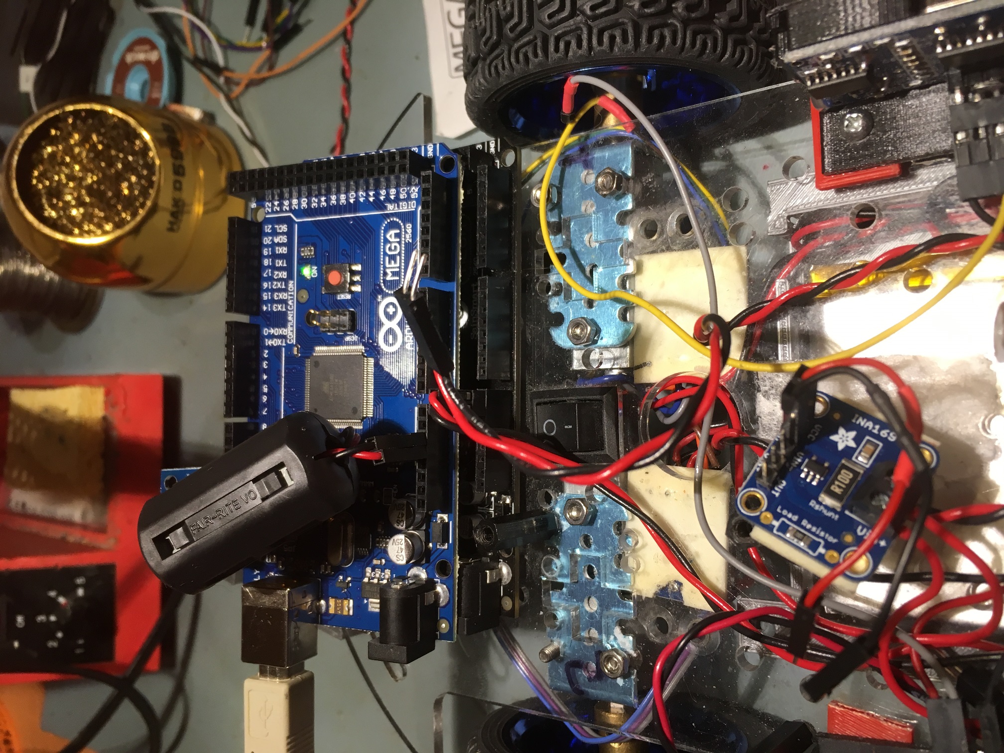
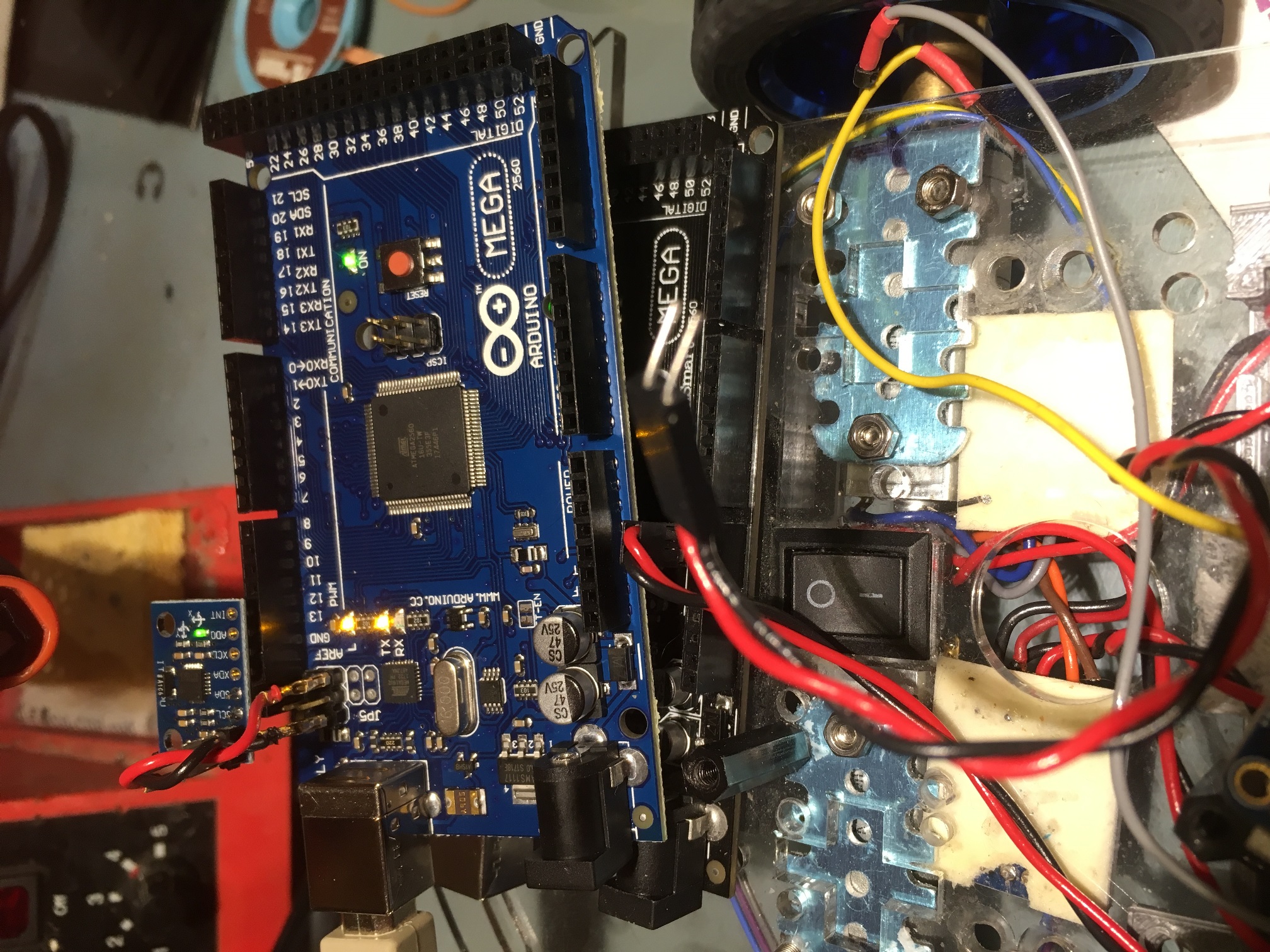
I received a new batch of GY-521 MPU6050 breakout boards, so I decided to try a few more experiments.  With one of the GY-521 modules, I soldered the SCL/SDA header pins to the ‘bottom’ (non-label side) and the PWR/GND pins to the ‘top’.  With this setup I was able to plug the module directly into the Mega’s SCL/SDA pins, thereby reducing the I2C cable length to zero.  The idea was that if the I2C cable length was contributing significantly to RFI susceptibility, then a zero length cable should reduce this to the minimum  possible, as shown below:

MPU6050 directly on Mega pins, normal length power wiring

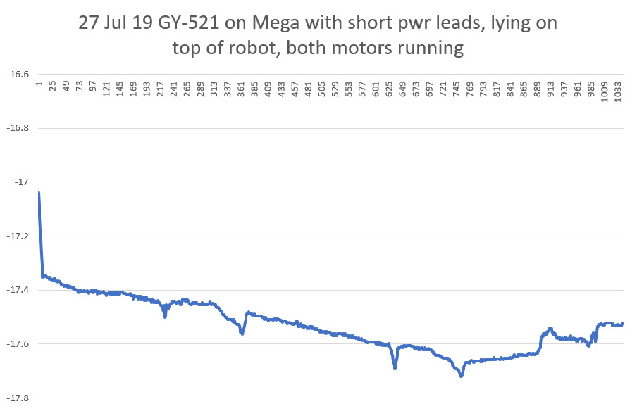
In the photo above, the Mega with the MPU6050 connected is sitting atop the Mega that is running the motors. The GND and +5V leads are normal 15cm jumper wires.  As shown in the plots below, this configuration did reduce the RFI susceptibility some, but not enough to allow normal operation when lying atop the robot’s Mega.

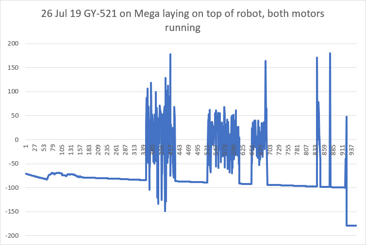
GY-521 MPU6050 module mounted directly onto Mega, normal length power leads

I was at least a little encouraged by this plot, as it showed that the MPU6050 (and/or the Mega) was recovering from the RFI ‘flooding’ more readily than before.  In previous experiments, once the MPU6050/Mega lost sync, it never recovered.

Next I tried looping the power wiring around an ‘RF choke’ magnetic core to see if raising the effective impedance of the power wiring to high-frequency transients had any effect, as shown in the following photo.

GND & +5V leads looped through an RF Choke.

Unfortunately, as far as I could tell this had very little positive effect on RFI susceptibility.

Next I tried shortening the GND & +5V leads as much as possible.  After looking at the Mega pinout diagram, I realized there was GND & +5V very close to the SCL/SDA pins, so I fabricated the shortest possible twisted-pair cable and installed it, as shown in the following photo.

MPU6050 directly on Mega pins, shortest possible length power wiring

With this configuration, I was actually able to get consistent readings from the MPU6050, whether or not the motors were running – yay!!

In the plot above, the vertical scale is only from -17 deg to -17.8 deg, so all the variation is due to the MPU6050, and there is no apparent deleterious effects due to motor RFI – yay!

So, at this point it’s pretty clear that a significant culprit in the MPU6050’s RFI susceptibility is the GND/+5V and I2C cabling acting as antennae and  conducting the RFI into the MPU6050 module.  Reducing the effective length of the antennas was effective in reducing the amount of RFI present on the module.

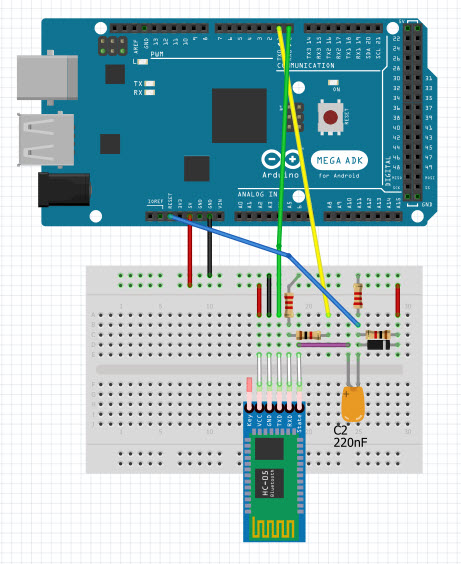
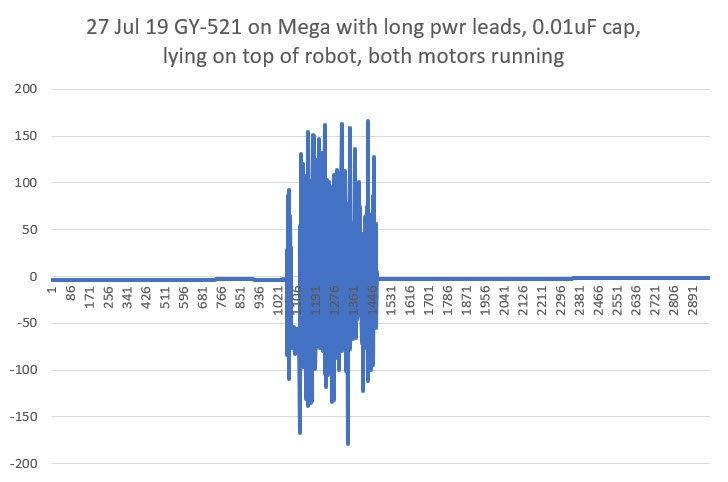
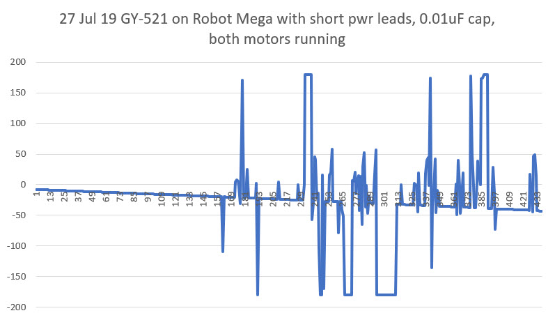
With the above in mind, I also tried adding a 0.01uF ‘chip’ capacitor directly at the power input leads, thinking this might be just as effective (if not more so) than shortening the power cabling.  Unfortunately, this experiment was inconclusive. The normal length power cabling with the capacitor seemed to cause just as much trouble as the setup without the cap, as shown in the following plot.

Having determined that the best configuration so far was the zero-length I2C cable and the shortest possible GND/+5V cable, I decided to try moving the MPU6U6050 module from the separate test Mega to the robot’s Mega. This required moving the motor drive lines to different pins, but this was easily accomplished.  Unfortunately, when I got everything together, it was apparent that the steps taken so far were not yet effective enough to prevent RFI problems due the switch-mode motor drivers

The good news, such as it is, is that the MPU6050/Mega seems to recover fairly quickly after each ‘bad data’ excursion, so maybe we are most of the way there!

As a next step, I plan to replace the current DRV8871 switch-mode motor drivers with a single L298N dual-motor linear driver, to see if my theory about the RFI problem being mostly due to the high-frequency transients generated by the drivers and not the motors themselves.  If my theory holds water, replacing the drivers should eliminate (or at least significantly suppress) the RFI problems.

28 July 2019 Update:

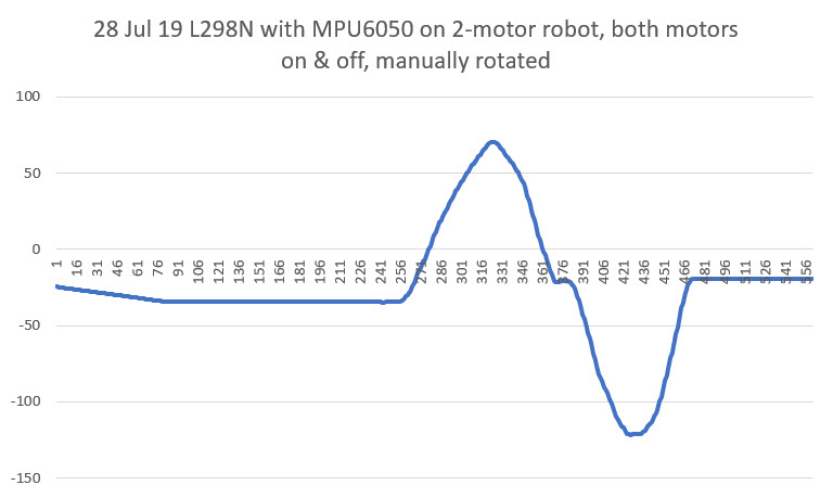
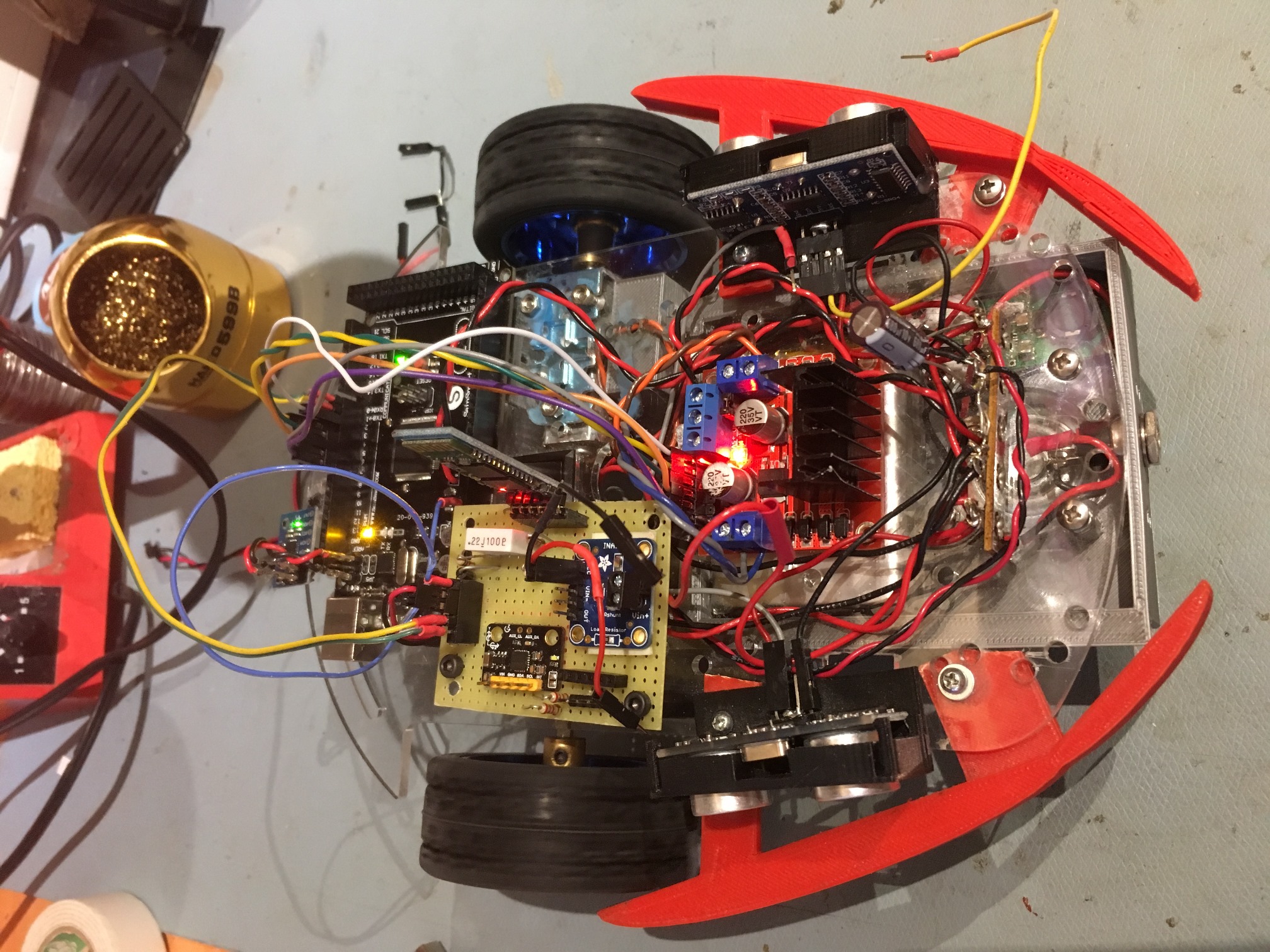
So today I got the L298N driver version of the robot running, and I was happy (but not too surprised) to see that the MPU6050 can operate properly with the motors ON  or OFF when mounted on the robot’s Mega controller, as shown in the following photo and Excel plots

2-motor robot with L298N motor driver installed.

However, there does still seem to be one ‘fly in the ointment’ left to consider.  When I re-installed the wireless link to allow me to reprogram the 2-motor robot remotely and to receive wireless telemetry, I found that the MPU6050 exhibited an abnormally high yaw drift rate unless I allowed it to stabilize for about 10 sec after applying power and before the motors started running, as shown in the following plots.

2-motor robot with HC-05 wireless link re-installed.

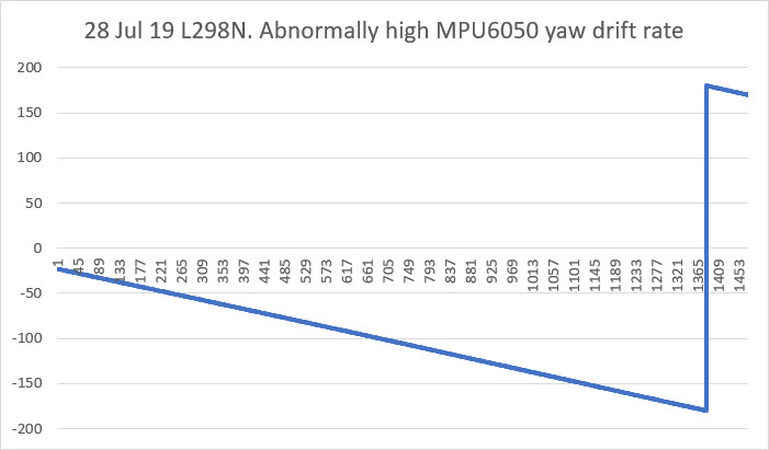
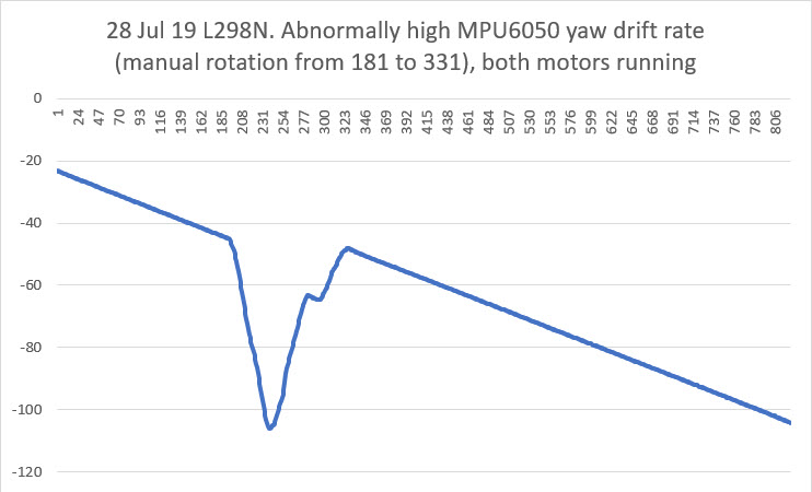
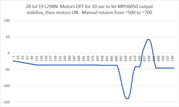
I have no idea what is causing this behavior.

31 July 2019 Update

So, I found a couple of posts that refer to some sort of auto-calibration process that takes on the order of 10 seconds or so, and that sounds like what is happening with my project.  I constructed the following routine that waited for the IMU yaw output values to settle

This was very effective in determining when the MPU6050 output had settled, but it turned out to be unneeded for my application.  I’m using the IMU output for relative yaw values only, and over a very short time frame (5-10 sec), so even high yaw drift rates aren’t deleterious.  In addition, this condition only lasts for a 10-15 sec from startup, so not a big deal in any case.

At this point, the MPU6050 IMU on my little two-motor robot seems to be stable and robust, with the following adjustments (in no particular order of significance)

  • Changed out the motor drivers from 2ea switched-mode DRV8871 motor drivers to a single dual-channel L298N linear mode motor driver.  This is probably the most significant change, without which none of the other changes would have been effective.  This is a shame, as the voltage drop across the L298N is significantly higher than with the switch-mode types.
  • Shortened the I2C cable to zero length by plugging the GY-521 breakout board directly into the I2C pins on the Mega.  This isn’t an issue on my 2-motor test bed, but will be on the bigger 4-motor robot
  • Shortened the IMU power cable from 12-15cm to about 3cm, and installed a 10V 1uF capacitor right at the PWR & GND pins on the IMU breakout board.  Again, this was practical on my test robot, but might not be on my 4-motor robot.
  • Changed from an interrupt driven architecture to a polling architecture.  This allowed me to remove the wire from the module to the Mega’s interrupt pin, thereby eliminating that possible RF path.  In addition, I revised the code to be much stricter about using only valid packets from the IMU.  Now the code first clears the FIFO, and then waits for a data ready signal from the IMU (available every 50 mSec at the rate I have it configured for).  Once this signal is received, the code immediately reads a packet from the FIFO if and only if it contains exactly one packet (42 bytes in this configuration).  The code shown below is the function that does all of this.

Here’s a short video of the robot making some planned turns using the MPU6050 for turn management.  In the video, the robot executes the following set of maneuvers:

  1. Straight for 2 seconds
  2. CW for 20 deg, starting an offset maneuver to the right
  3. CCW for 20 deg, finishing the maneuver
  4. CCW for 20 deg, starting an offset maneuver to the left
  5. CW for 20 deg, finishing the maneuver
  6. 180 deg turn CW
  7. Straight for 3 sec
  8. 20 deg turn CCW, finishing at the original start point

So, I think it’s pretty safe to say at this point that although both the DFRobots and GY-521 MPU6050 modules have some serious RFI/EMI problems, they can be made to be reasonably robust and reliable, at least with the L298N linear mode motor drivers.  Maybe now that I have killed off this particular ‘alligator’, I can go back to ‘draining the swamp’ – i.e. using relative heading information to make better decisions during wall-following operations.

Stay tuned!

Frank


Arduino Remote Programming Using A HC-05 Bluetooth Module

Posted 10 June 2019

As part of my recent Wall-E2 Motor Controller Study, I reincarnated my old 2-motor robot as a test platform for Pololu’s ’20D’ metal gear motors.  When I got the robot put together and started testing the motors, I realized I needed a way to remotely program the Arduino controller and remotely receive telemetry, just as I currently do with my 4-wheel Wall-E2 robot.

On my Wall-E2 robot, remote programming/telemetry is accomplished using the very nice Pololu Wixel Shield.  However, I have been playing around with the cheap and small HC-05 Bluetooth module,  and decided to see if there was maybe a way to use this module as a replacement for the Wixel.

As I usually do, I started with LOTS of web research.  I found some posts claiming to have succeeded in remotely programming an Arduino using a HC-05 module, but the information was sketchy and incomplete, so I decided I would try and pull all the various sources together into a (hopefully) more complete tutorial for folks like me who want to use a HC-05 module for this purpose.

Overall Approach:

In order to remotely program an Arduino using a HC-05, the following basic parts are required:

  • A wireless link (obviously) between the PC and the HC-05.
  • A serial link between the PC and the Arduino and between the Arduino and the HC-05. This part is also well established, and the Arduino-to-HC-05 link can be done with either a hardware port (as with the Mega 2560) or a SoftwareSerial port using the SoftwareSerial library.  My tutorial uses the Mega 2560, so I use Tx/Rx1 (pins 18/19) for the Arduino-to-HC-05 link
  • A way of resetting the Arduino to put it back into programming mode, so the new firmware can be uploaded.
  • A serial connection between the HC-05 and Tx/Rx0 on the microcontroller – more about this later.

The Wireless Link

The HC-05 is a generic Bluetooth device, and as such is compatible with just about everybody’s Bluetooth setup – phones and PC’s.  I plan to use this with my Dell XPS15 9570 laptop, and I can pair with the HC-05 no problem.  Here’s a link to a tutorial on pairing with the HC-05, and here’s another.  As another poster mentioned, the pairing mechanism creates multiple ‘outgoing’ and ‘incoming’ COM ports, and it’s hard for me to figure out which to use.  In this last iteration, I found that I could remove the two ‘incoming’ COM ports and use just the ‘outgoing’ one. Don’t know if that is the right thing, but….

A serial link between the PC, the Arduino and the HC-05

This part is discussed and demoed in many tutorials, but the piece that is almost always missing is why you need to have this link in the first place. The reason is that several AT commands must be used in order to configure the HC-05 correctly for wireless Arduino program upload, and (as I understand it anyway), AT commands can only be communicated to the HC-05 via it’s hardware serial lines, and only when the HC-05 is in ‘Command’ or ‘AT’ mode.  The configuration step is a one-time deal; once the HC-05 is configured, it does not need to be done again unless the application requirements change.

A way of resetting the Arduino to accept firmware uploads

This is the tricky part.  As ‘gabinix’ said in this post:

Hi Paul… To be honest I couldn’t find any tutorials to explain how to program/upload sketches with the HC-05. In fact, the conclusion you came up with is in-line with all the information out there. But it’s actually an extremely simple solution.

The only thing that keeps the HC-05 from uploading a program to arduino is that it doesn’t have a DTR (Data Terminal Ready) pin which tells the arduino to reset and accept a new sketch.

The solution is to re-purpose the “state” pin (PI09)  on the breakout board. It’s purpose is to attach to an LED and indicate the connection status. It’s default setting is to send the pin HIGH when a connection is made, but you can simply enter into command mode of the HC-05 and use an AT COMMAND to tell it to send the pin LOW when a connection is made.

Voila! In about 1 minute of time you have successfully re-purposed the LED pin to a DTR pin which will reset your arduino to accept a new sketch when you hit the upload button.

A couple things to note… This will work for a pro-mini without additional hardware by connecting to the DTR pin. If you’re using an UNO or similar, you will need a capacitor in between our custom “state” pin and the reset pin on the uno. The reason is that the HC-05 will drive our custom pin LOW for the entire connection which would essentially be the same as holding the reset button the entire time. Having the cap in between solves that problem.

It a quick easy fix, takes about a minute to do. It’s just a lot harder to explain the steps to do it in a couple sentences.

Here’s a link to the AT COMMAND set —> http://robopoly.epfl.ch/files/content/sites/robopoly/files/Tutoriels/bluetooth/hc-05-at_command_set.pdf

and here’s a link to a tutorial, video, and sketch on how to enter the AT COMMANDS. —> http://www.techbitar.com/modify-the-hc-05-bluetooth-module-defaults-using-at-commands.html  <<< no longer available 🙁

So, the trick is to re-purpose the STATE output (PI09, AKA Pin 32, AKA LED2, see this link) via the AT+POLAR(X,0) command to go LOW when the connection to upload the program is first started.  This signal is then connected to the Arduino’s RESET pin via the capacitor noted above (to make this signal momentary).  The ‘Instructables’ tutorial on this subject at this link actually gets most of this right, except it doesn’t explain why the AT commands are being entered or what they do – so I found it a bit mysterious.  In addition, it recommends soldering a wire directly to pin 32 rather than re-purposing the STATE output pin (re-purposing the STATE pin allows a no-solder setup). Eventually I ran across this link which contains a very good explanation of the AT commands used by the HC-05.  The required AT commands are:

AT+ORGL  // resets the HC-05 to its original default state. AT mode must be re-established after this command

AT+ROLE=0 // sets it to 'slave' mode (prob not necessary as this is the default, but...

AT+POLAR=1,0 // sets the LED2/Pin32/STATE 'Connection' output to active LOW.

AT+UART=115200,0,0 // changes HC-05 'Data' (Bluetooth) Mode baud rate from the default 9600 to 115,200/0/0. Does not affect wired 'Command' (AT) Mode

AT+INIT // Initialize SPP Profile.


My module is the variety with a small pushbutton already installed on the ‘EN’ pin, so entering ‘Command’ mode is accomplished by holding the pushbutton depressed while cycling the power, and then releasing the button once power has been applied.

When this is done, the LED will change from fast-blink to a very slow (like 2 sec ON, 2 sec OFF) blink mode, as shown in the following short video:

This indicates the HC-05 is in ‘Command’ mode and will accept AT commands.  If you have the style without the pushbutton, you’ll have to figure out a way to short across the pads where the pushbutton should be, while cycling the power.

The screenshot below shows the result of executing these commands using the wired USB connection to the Arduino and the hard-wired serial connection between the Mega’s Tx1/Rx1 port and the HC-05 running in ‘Command’ mode.

HC-05 configuration using the wired serial port connection to the HC-05

NOTE:  The various posts and tutorials on the HC-05 describe separate AT ‘mini’ and ‘full’ command modes; the ‘mini’ mode only recognizes a small subset of all AT commands, while ‘full’ recognizes them all.  ‘Mini’ mode is entered by momentarily applying VCC to pin 34, and ‘full’ mode is entered by holding pin 34 at VCC for the entire session.  One poster described this as a flaw in the HC-05 version 2 firmware which might be corrected in later versions.  It appears this may have been the case, as the HC-05 module I used responded with VERSION:3.0-20170601 and recognized all the commands I gave it (not a comprehensive test, but enough to make me think this problem has gone away).

Wiring Layout for HC-05 Configuration via AT commands

I decided that this post was my chance to learn how to make ‘pictoral’ wiring diagrams using the Fritzing app.  I had seen other posts with this kind of layout, and initially thought it was kinda childish.  However, when I started working with Fritzing (in English, ‘Fritzing’ sounds like an adverb, not a proper noun – so a bit strange to my ears…), I realized it has a LOT of power, so now I’m a convert ;-).

HC-05 wired for initial configuration using AT commands

In the diagram above, I’m using the Rx1/Tx1 (pins 19/18) hardware serial port available on the Mega.  If you are using a Uno, you’ll need to use SoftwareSerial to configure a second port for connection to the HC-05.  A 2.2K/1.0K voltage divider is used to drop Arduino Tx output voltages to HC-05 Rx input levels, but no conversion is required in the other direction. The HC-05 can be powered directly from Arduino +5V, as the HC-05 has an onboard regulator.

Initial AT Configuration Arduino Sketch

void setup()
{
	Serial.begin(115200);
	Serial1.begin(38400);
}

void loop()
{
	if (Serial1.available())
	{
		Serial.write(Serial1.read());
	}
	if (Serial.available())
	{
		Serial1.write(Serial.read());
	}
}

All the code above does is transfer keystrokes from the Arduino to the HC-05, and vice versa. This is all that is required to configure the HC-05 using AT commands.

Serial Connection between the HC-05 and Tx/Rx0 for Program Uploads

Most Arduino microcontrollers are shipped with a small program called a ‘bootloader’ already installed.  This small program is only active for a few seconds after a board reset occurs, and it’s job is to detect when a new program is being uploaded.  If the bootloader sees activity on whatever serial port it is watching, it writes the incoming data into program memory and then transfers control to the user program.  The stock Arduino bootloader only monitors Tx/Rx0 for this; activity on other ports (specifically Rx1 in my case) will be ignored and program uploads will fail.  After the HC-05 has been initially configured via AT commands over the PC-to-Arduino-to-HC-05 serial links, the connection from the HC-05 to the Arduino must be changed so that PC-to-HC-05 data transferred over the Bluetooth link arrives at the Arduino’s Rx0 port so the stock bootloader will see it and write it to the Arduino’s program memory.  This minor point wasn’t at all clear (at least not to me) in the various tutorials, so I wasted a LOT of time trying to figure out why I couldn’t get the last part of the puzzle to fit – ugh!

Shown below is my Fritzing diagram for the final configuration of my test setup, showing the Tx/Rx lines changed from Tx/Rx1 (pins 18/19) to Tx/Rx0 (pins 1/0). The HC-05 STATE output is connected to Arduino reset via a 0.22uF capacitor, with resistors to form a simple one-shot circuit.  The STATE line goes LOW (after reconfiguration via the AT+POLAR=1,0 command) which causes a momentary LOW on the Arduino reset line.  This is the magic required to upload programs to the Arduino wirelessly. When the Bluetooth connection is terminated, the STATE line goes HIGH again and the Arduino end of the now-charged capacitor jumps to well above 5V. The diode shown on the diagram clamps this signal to within a volt or so above +5V to avoid damage to the Arduino Reset line when this happens.  This diode isn’t shown on any of the other tutorials I found, so it is possible the Arduino Reset line is clamped internally (good).  It’s also possible it isn’t protected, in which case not having this diode will eventually kill the Arduino (bad).

HC-05 wired for remote program upload. Note that the Tx & Rx lines have been moved from Tx/Rx1 to Tx/Rx0

Testing

The first thing I did after configuring the HC-05 (using the above AT commands) was to see if I could still connect to and communicate with it over Bluetooth from my laptop.  I used RealTerm, although any terminal program (including the Arduino IDE serial monitor) should do.  The very first thing that happened is I had to re-pair the laptop with the HC-05, and the name given by the HC-05 was markedly different, as shown in the captured pairing dialog.

Pairing dialog on my Dell XPS15 9570 laptop

The next thing was to see if I could get characters from my BT serial connection through to my Arduino serial port.  After fiddling around with the baud rates for a while, I realized that now I had to change the BT serial terminal baud rate from 9600 to 115200, and the Arduino-to-HC-05 baud rate from 38400 (the default ‘Command’ mode rate) to 115200.  Once I did this, I could transmit characters back and forth between RealTerm (connected to the HC-05 via Bluetooth) and my Visual Studio/Visual Micro setup (connected to Arduino via the wired USB cable) – yay!

For the next step in the testing, I need to remove the hard-wired USB connection and power the Arduino from an external power source.  When I did this by first removing the USB connector (thereby removing power from the HC-05) and then plugged in external power, I noticed that the HC-05 was no longer connected to my laptop (the HC-05 status LED was showing the ‘fast blink’ status, and my connection indicator LED was OFF).  I checked in my BT settings panel, and the HC-05 (now announcing itself as ‘H-C-2010-06-01’) was still paired with my laptop, but just transmitting some characters from my RealTerm BT serial monitor did not re-establish the connection.  However, when I changed the port number away from and then back to the BT COM port, this did re-establish the connection; the HC-05 status LED changed to the 2-blinks-pause-2-blinks cycle, and my connection LED illuminated.

So, now I connected the output of my STATUS line one-shot circuit to the Arduino reset line and changed my VS2017/VM programming port from the wired USB port to the BT port (interestingly it was still shown as ‘HC-05’ in Visual Studio/Visual Micro).  After some initial problems, I got the ‘Connected’ status light, but the upload failed with the error message “avrdude: stk500v2_getsync(): timeout communicating with programmer” and the communication status changed back to ‘not connected’.

At this point I realized I was missing something critical, and yelled (more like ‘pleaded’) for help on the Arduino forum.  On the forum I got a lot of detailed feedback from very knowledgeable users, most notably ‘dmjlambert’.  Unfortunately dmjlambert was ultimately unsuccessful in solving the problem, but he was able to validate that the steps I had taken so far were correct as far as they went, and ‘it should just work’.  To paraphrase the Edison approach to innovation, “we didn’t know what worked, but we eliminated most potential failure modes”.  See this forum post for the details.

After this conversation (over several days), I decided to put the problem down for a few days and do other things, hoping that a fresh look at things with a clear head might provide some insight.  A few days later when I came back to the project, I ran some tests suggested by dmjlambert to verify that the connection to the Arduino RESET pin via the 0.22uF capacitor did indeed reset the Arduino when the STATE line transitioned from HIGH to LOW.  To do this I created a modified ‘Blink’ program that blinked 10 times rapidly and then transitioned to a steady slow blink.  Using this program I could see that that the Arduino did indeed reset each time a Bluetooth connection to the HC-05 was established.

So, the problem had to be elsewhere, and about this time I realized I was assuming (aka ‘making an ass out of you and me’) that the program upload data being received over the Bluetooth link was somehow magically making it to the bootloader program.  This had been nagging at me the whole time, but I ‘assumed’ (there’s that word again) that since this problem had never been mentioned in any of the tutorials or even in the responses to my forum posts, it must not be a problem – oops!

Anyway, to make a long story short, I moved the HC-05 – to – Arduino connection from Rx/Tx1 to Rx/Tx0 and program uploads started working immediately – YAY!!

I went back through the tutorials I had been following to see if I had missed this magic step, and didn’t find any references to moving the serial connection at all.  So, if you are doing this with a UNO, you’ll need to move the serial connection from whatever pins  you were using (via SoftwareSerial) to Rx/Tx0 as the last step.  If you are using an Arduino Mega or other uino controller that supports additional hardware serial ports as I did, you’ll have to move the connection from Rx/Tx-whatever to Rx/Tx0 as the last step.

This tutorial was put together in the hope that I could maybe help others who are interested in using the HC-05 Bluetooth module for remote program uploads to a Arduino-compatible microcontroller, and maybe save them from some of the frustration I experienced.  Please feel free to comment on this post, especially if you see something that I got wrong or missed.

13 Aug 2019 Update:

Here’s a short video showcasing the ability to program an Arduino Mega 2560 wirelessly from my Windows 10 PC using the HC-05 Bluetooth module

At the start of the video, the HC-05 status light is blinking rapidly, signalling the ‘No Connection’ state.  Then, at about 2 seconds, the light changes to the slow double-blink ‘Connected’ state, the yellow LED on the Mega blinks OFF & then ON again, signalling that the Mega has been reset and is now awaiting program upload, followed immediately by rapid blinking as the new program is uploaded to the Mega’s program memory.  During the upload, the HC-05 status LED continues to show the slow double-blink ‘Connected’ status.  Then, at about 18 seconds, the program upload terminates and the HC-05 returns to the ‘No Connection’ state.

The small white part on the green perf-board is the 220 nF capacitor.  The other two modules on the perf-board are a MPU6050 IMU and a high-side current sensor.

Stay tuned!

Frank


25 October 2021 Update:

I came back to this post to refresh my memory when trying to initialize and use a new HC-05 module for my new Wall-E3 project, and failing badly. I finally got something to work, but only after screwing around a lot. I realized I didn’t have a good handle on what mode the HC-05 was in – even though the onboard LED changes behavior to indicate the mode. So, here is a short video showing the LED behavior for the ‘disconnected’ and ‘connected’ modes.

HC-05 LED indications for ‘connected’ and ‘disconnected’ modes

In the above video, the HC-05 starts out in the normal power-on ‘disconnected’ state (rapidly flashing LED). Then after a few seconds a BT connection is established, and the LED behavior changes to ‘connected’ (two short blinks and a long pause). Then after a few more seconds the connection is dropped and the LED behavior changes back to ‘disconnected’ (rapidly flashing)

Wall-E2 Motor Controller Study

Posted 19 May 2019

Over the last few weeks I have noticed that Wall-E2, my wall-following robot, seems to be suffering from a general lack of energy.  I’ve been doing some testing involving a series of 45 degree S-turns, and Wall-E2 is having trouble moving at all, and when it does move, it does so very slowly.  At first I thought this might be due to a low battery condition, but it exhibits the same behavior even with a fully charged battery pack.  Then I thought it might be the battery pack itself dying, but now that I can monitor Wall-E2’s operating current and voltage ‘on the fly’ it is apparent that the battery pack is healthy and delivering rated power – it’s just that the power doesn’t seem to be getting to the motors.  About this same time I began noticing that the cheap L298N motor drivers I have been using were getting pretty hot; enough to burn my finger, and enough to cause a ‘burning insulation’ smell.

So, I decided to go back to the drawing board and see what else is out there in terms of ‘better’ (whatever that means) motor and motor driver technology. As usual I started with a broad internet search and then started narrowing down to specific technologies and modules as I learned more.  What I learned right away is that the L298n technology is notoriously inefficient, as it uses a bipolar transistor H-bridge which pretty much guarantees 1-2V voltage drop between the motor power supply and the motors themselves.  This technology has been superceded by MOSFET-based H-bridge modules with much lower voltage drops and commensurately higher efficiencies.  In fact, most of the modules I found no longer require heat sinks due to the much lower power dissipation.

VNH5019 Motor Driver Carrier

The Pololu VNH5019 Motor Driver Carrier is a single-channel motor driver based on the STMicroelectronics VNH5019 chip, with the following major features:

  • Relatively high cost compared to other products – about $25 ea.
  • 5.5 – 24V operating range. This matches well with Wall-E2’s battery output range of 7-8.4V.
  • Very low Rds(ON) – less than 100mΩ.  This means almost no voltage drop at the typical motor operating current of 100-200mA, and only about 0.2V at 2A stall current, or 0.4W power dissipation, worst case.
  • Peak operating current of 12A – way more than I’ll need.
  • There is also a current sensing output, but it’s only accurate during the active drive portion of the PWM waveform. Although I could probably deal with this by timing measurements to coincide with the drive cycle, I probably won’t bother, as I already have independent current measurement capability.
  • Very simple operation – essentially identical to the L298n scheme.

There are, however, two major drawbacks to this option; the first is that the modules are single-channel only, so I either need to use four (one for each motor) or run two motors in parallel. The second is that they are much more expensive (like an order of magnitude) than the L298n driver modules.

TB67H420FTG Dual/Single Motor Driver Carrier

Pololu’s TB67H420FTG Dual/Single Motor Driver Carrier uses the Toshiba TB67H420FTG part, with the following features:

  • Single or dual channel operation.  In dual motor mode, each channel is limited to 1.7A, which should be OK for Wall-E2’s motors.
  • Minimum motor drive voltage is specified as 10V.  This is too high for my 2-cell LiPo setup that tops out at 8.4V.  It’s still possible it will work OK down to 7V, but only experimentation will tell

Well, this is a much cheaper part ($10 vs $25) and each part can potentially handle twice the number of motors. Nominally $20 for four motors vs $100.  However, the minimum motor voltage of 10V is probably a deal breaker.  Besides, if I parallel two motors on each VNH5019 module, the price differential drops to 2.5:1 vs 5:1 and I don’t have to worry about the minimum motor supply voltage.

TB9051FTG Single Brushed DC Motor Driver Carrier

The Pololu TB9051FTG brushed DC motor driver is based on Toshiba’s TB9051FTG part, and has the following features:

  • Low price – $8.49 (single channel)
  • Compatible motor supply voltage range (4.5 – 28V).
  • Can deliver 2.6A continuously, which should be much more than I’ll ever need
  • 1″ x 1″ form factor, so fitting four modules onto Wall-E2’s chassis shouldn’t be too much of a problem

According to the TB9051FTG’s datasheet, the Rds(ON) has a max of 0.45Ω, so very little IR drop & power loss.  This could make a very nice setup, even if I have to use four modules.  This will still cost much more than my current dual L298n setup, but well worth it for the much lower voltage drop.

Dual TB9051FTG Motor Driver Shield for Arduino

This board is a dual-channel version of the above single-channel part, sized and laid out as an Arduino compatible ‘shield’ module. Pertinent features:

  • $19.95 ea – essentially the same per-channel price as the single channel version
  • Same voltage (4.5 – 28V) & current (2.6A continuous) range per channel
  • Motor driver control pins broken out on one side so can be used without an Arduino
  • Size is 1.9″ x 2.02″ or about 4 times the area of the single-channel boards. This is undoubtedly due to the requirement to physically match the Arduino Uno/Mega pin layout.

This isn’t really a good option for my Wall-E2 project, as I can fit four of the single channel modules in the same footprint as one of these boards – effectively making a 4-channel version in the same footprint.

Dual MAX14870 Motor Driver for Raspberry Pi (Partial Kit)

This module uses the Maxim MAX14870 part on a board physically compatible with the later versions of the Raspberry Pi microcomputer.  Pertinent parameters

  • Reasonable cost – $12.75 means the per-channel cost is around $6.50/channel.
  • Small size:  0.8″ x 1.7″, so all four channels would fit in a 1.6″ x 1.7″ space. This is significantly smaller than the 2 x 2″ space requirement for 4 ea TB9051FTG modules
  • Same 4.5 – 28V motor supply range, and same 1.7A continuous/channel current rating.
  • Low Rds(ON) – less than 0.3Ω

This unit looks very promising; it’s small size and form factor, combined with dual motor control could make it the winner in the ‘replace the L298n’ project.

Adafruit DRV8833 DC/Stepper Motor Driver Board

This is a dual H-bridge for higher current applications than the non-current-limiting Featherwing can handle.  It can handle one stepper or two DC brushed motors and can provide about 1.2A per motor, and expects a motor drive input of 2.7-10.8VDC.  From the documentation:

  • Low MOSFET ON resistance (approx 360 mΩ)
  • 1.5A RMS output current, 2A peak per bridge
  • Power supply range 2.7 – 10.8 V
  • PWM winding current regulation and Current Limiting
  • Overcurrent protection, short-circuit protection, undervoltage lockout, overtemp protection
  • Reasonable per-channel cost; $5 per module, but each module will handle two motors – nice!

Adafruit DRV8871 Single Channel Motor Driver:

This is a single H-bridge for even higher current applications.  From the documentation:

  • 6.5V to 45V motor power voltage
  • Up to 5.5V logic level on IN pins
  • 565mΩ Typical RDS(on) (high + low)
  • 3.6A peak current
  • PWM control
  • Current limiting/regulation without an inline sense resistor
  • Overcurrent protection, short-circuit protection, undervoltage lockout, overtemp protection
  • Higher per-channel cost; $8 per module, so $32 for all 4 motors

I was thinking that I might be able to use just two of these modules and parallel the left motors on one and the right motors on the other; this would give me 4 motor drives for $16, so comparable to the DRV8833.  However, even if I use one per channel, the 4 units would still occupy a smaller footprint than the current setup with two L298N driver modules (and even less if I stack them vertically)

Adafruit Featherwing Motor Driver:

The Adafruit Featherwing motor driver kit is intended to plug into Adafruit’s ‘Feather’ microcontroller product, so to integrate it into my Mega 2560 project I’ll need to make sure I interface to the proper pins, etc.  The module uses I2C for communications and motor control, so the low-level drivers for this module will be quite different than the ones currently in use for my Wall-E2 robot.  Looking over the Adafruit documentation, I get the following:

  • Motor Power and Motor outputs:  these are all on 2-pin terminal blocks, so no changes
  • Logic Power Pins:  The Featherwing requires 3.3V & GND on the 2nd & 4th pins on the ‘long’ header side, counting from the end with three terminal blocks.
  • I2C Data Pins: Last two pins on the ‘short’ header side
  • I2C Addressing:  The default feather address is 0x60, so it should be OK. The Wall-E2 project currently has four devices connected to the I2C bus;
    • IR Homing Teensy uC slave at addr = 0x08
    • FRAM module at addr = 0x50
    • DS3231 RTC at addr = 0x68 (fixed)
    • MPU6050 IMU module at addr = 0x69
  • Smaller voltage range (4.5 – 13.5V), but OK for my 2-cell LiPo application with max V <= 8.5V
  • Lower max current rating – 1.2A/channel; this could be a problem, but I don’t think so; the motors draw less than 0.5A, and won’t ever need 1.2A except in stalled rotor configuration, where it doesn’t matter. However, there is no current limiting on the Featherwing, so it is entirely possible to burn out a channel if the limit is exceeded!
  • Reasonable cost on a per-channel basis. The board costs $20, but it will drive all four motors, for a per-motor cost of only $5 – nice!

So, I ordered several of each of the above parts, with the idea of running some simple tests of each and picking the one that best suits my application

Adafruit Featherwing Motor Driver Testing:

The first unit I tested was the Adafruit FeatherWing.  I set up a spare Mega 2560 as the controller. This turned out to be quite simple, as there are only four connections; 3.3V, GND, SCL and SDA.  I used my DC lab power supply to provide 8.0V, and used two spare JGA25-370 geared DC motors connected to M1 and M3 for the test. As the following short video shows, this worked great.

As a side-effect of this test, I noticed that one of the JGA25-370 210RPM gear motors seemed to be behaving a little differently than the other.  After some experimentation, I discovered that one motor required a speed control input of almost half the full-speed value to even start turning, while the other one seemed to respond correctly to even low level speed drive values.  Some more investigation revealed that the ‘problem’ motor was definitely stiffer than the ‘good’ one, and when the problem motor was being driven from my lab power supply, the power supply output current went up to almost 1A until the motor started moving and then dropped down to under 100mA while the motor was actually running. The ‘good’ motor current stayed under 100mA for the entire range of speeds.

I continued by connecting all four JGA25 gear motors and noticed that only one was really functioning properly, and the other three all had difficulty at low commanded speeds.  To investigate further, I added an Adafruit INA219 high-side current sense module to the circuit so I could record both the current and power for each step on each channel.  I ran all 4 motors in sequence, and then plotted the results in Excel as shown below

Testing all 4 JGA25-370 motors

Current and Power vs time for 4 JGA25-370 motors.  Note the current/power spikes when the ‘sticky’ motors turn ON

After some posts on the Adafruit forum, I was able to troubleshoot the motor problems to some extent. I was able to free up one of the troublesome motors by exercising the gear train, but on two other motors it became obvious that it was the motors themselves, not the gear train that was sticking.  A 50% (or 75% depending on one’s threshold) failure rate isn’t very good.  One of the posters on the Adafruit forum suggested I take a look at the metal gear motors offered  by Pololu, and I ordered some of their ’20D’ motors for evaluation.

After testing the metal gear motors, I tried some of my stock of plastic motors, as shown in the following photo and Excel plot.

two ‘red cap’ and two ‘black cap’ motors

Current and Power vs time for two ‘red cap’ and two ‘black cap’ motors

All four motors behaved reasonably well, but as shown in the above plot, the ‘red cap’ motors drew a LOT more current than the ‘black cap’ ones. This was a mystery to me until I measured the coil resistance of the two types.  The ‘red cap’ motors exhibited coil resistances of about 1Ω, whereas the ‘black cap’ motors were more like 5.7Ω.  I surmise that the ‘red cap’ motors are for 3V applications and the ‘black cap’ ones are for 6-12V.

After this, I decided to test the motors currently installed in my Wall-E2 robot, so I simply placed the prototype board containing the Featherwing and the Mega 2560 controller on top of the robot and rerouted the motor wires from the LN298 controllers to the Featherwing. The following photo and plot show the setup and the results.

proto board on top of Wall-E2

Current and Power vs time for the four ‘red cap’ motors currently installed in Wall-E2

Of the four installed ‘red cap’ motors currently installed in Wall-E2, only two (M1 & M4 above) exhibited reasonable performance – the other two were basically inoperative. Some closer inspection revealed that M3 exhibited essentially infinite coil resistance, i.e. an open circuit.  Apparently I had managed to burn out this coil entirely, probably because the ‘red cap’ motors were intended for lower voltage applications.

Adafruit DRV8871 Single Channel Motor Driver Testing:

I removed the Featherwing module and replaced it with Adafruit’s DRV8871 Driver module. This module uses two PWM outputs to drive and direction control (vs I2C for the Featherwing) and is very simple to hook up and use.  After getting it hooked up I ran a Pololu ’20D’ metal gear motor and a ‘good’ JGA25-370 over one complete up/down speed cycle, with no mechanical load. This produced the plots shown below:

Pololu 20D metal gear motor with DRV8871 Motor Driver

JGA25-370 metal gear motor with DRV8871 Motor Driver

Since I had already tested the same JGA25-370 motor with the Featherwing driver, I thought I would get similar results.  However, the earlier Featherwing test produced a significantly different plot, as shown below

JGA25-370 metal gear motor with Featherwing driver

Why the differences?  The coarseness of the DRV8871 plot versus Featherwing may well be because the DRV8871 uses the Arduino PWM outputs at the default frequency of around 980Hz, and I suspect the Featherwing PWM frequency is much higher.  However, this doesn’t explain the dip in both power & current at the peak of the speed curve.


Frank


Back to the future with Wall-E2. Wall-following Part III

Posted 24 March 2019,

In my previous post on this subject, I described some initial wall-following tests using a PID controller, and concluded that I would have to use some sort of two-stage approach/capture arrangement to make things work properly.  In addition, I needed some more ‘field’ (i.e., my hallway) testing to determine the best PID values for wall-following.

I started by causing the distance input to vary in a square wave fashion with an amplitude of about 20cm around the 50cm target value.  The resulting speed variations are shown in the following Excel plot.  This gave me some confidence that the basic PID mechanism was working properly.

Square wave response of PID = 1,0,0

After verifying basic operation, I started field testing with the most basic values possible – PID = 1,0,0:  This resulted in a very slow oscillation, as shown in the following video and Excel plot:

PID = 1,0,0, initial offset = target distance = 50cm

Then I moved on to the PID value I had obtained from previous field testing, i.e. PID = 10,0,0. This resulted in the behavior shown in the following video and Excel plot

PID = 10,0,0, initial offset = target distance = 50cm

For completeness, I also tested the PID = 10,2,0 case, but as can be seen in the following video and Excel plot, this did not appreciably change wall-tracking performance, at least not for the offset = target case.

PID = 10,2,0, initial offset = target distance = 50cm

A comparison of all three PID values is shown in the following Excel plot

Next I tried the PID = 1,0,0 case with an initial offset of 25cm and a target of 50cm, to gauge how the PID algorithm performs with an initially large error term.

PID = 1,0,0, initial offset = 25cm, target distance = 50cm

Upgraded Variance Calculation for Wall-E2 ‘Stuck’ Detection

Posted 23 April 2019

A little over three years ago I developed an effective technique for detecting when Wall-E2, my autonomous wall-following robot, had gotten itself stuck and needed to back up and try again.  The technique, described in that post, was to continuously calculate the mathematical variance of the last N forward distance measurements from the onboard LIDAR module.  When Wall-E2 is moving, the forward distances increase or decrease, and the calculated variance is quite high (generally in the thousands).  However, when it gets stuck the distances remain steady, and then the variance decreases rapidly to near zero. Setting a reasonable threshold allows Wall-E2 to figure out it is stuck on something and take appropriate action to recover.

The above arrangement has worked very well for the last three years, but recent developments and some nagging concerns prompted me to re-examine this feature.

Computational Load:

When I first added the variance calculation routine, there was very little else going on in Wall-E2’s brain; ping left, ping right, LIDAR forward, calc variance, adjust motor speeds, repeat.  Since then, however, I have added a number of different sensor packages, all of which add to the computational load in one way or another. I began to be concerned that I might be about to exceed the current 100 mSec time budget.

Performance Problems:

Although the LIDAR/Variance technique has performed very well, there were still occasions where Wall-E2’s behavior indicated something was wrong; either he would think he was stuck when he obviously wasn’t, or it would take too long to detect a stuck condition, or other random glitches.  This didn’t happen very often, but just enough to  put me on notice that something wasn’t quite right.

Brute Force vs Incremental Variance Calculation:

I could only think of two ways to address the computational load; reduce the size of the array of LIDAR distances used, or reduce the time required for each computation.  The original size selection of 50 measurements was sort of based on the idea that it would take about 5 seconds for a 50-entry array to be completely refreshed at the current 10Hz loop frequency.  This means that Wall-E2 should be able to detect a stuck condition about 5 seconds after it happens.  Decreasing the array size would decrease the detection time more or less linearly, but would probably also increase the chances of a false positive.  The other alternative would be to find a way to speed up the variance calculation itself.

Variance is a measure of the variability of a dataset, and is defined as:

The current algorithm for computing the variance is a ‘Brute Force’ method that loops through the entire array of LIDAR distance values twice – once for computing the mean, and then again to compute the squared-difference term, before subtracting the squared mean from the squared difference term to get the final variance value, as shown below:

This works fine, but is computationally clunky.  With a 50-element array, this computation takes around 1.5 mSec.  This is only about 1.5% of the 100 mSec time window for a 10Hz cycle time, but still…

Starting from a slightly different definition of the variance calculation

and then expanding, manipulating algebraically and then recombining, we arrive at an incremental version of the variance formula, as shown below:

Incremental version of the variance expression

And this is implemented in the code section shown below:

The incremental calculation doesn’t use any loops and therefore is quite a bit faster, for no loss in accuracy.  For a 50-element array as above, the incremental calculation takes only about 220 uSec, or about 7-8 times faster than the ‘brute force’ technique.

As a side-benefit of changing from the ‘brute force’ to the incremental technique, I also discovered the reason Wall-E2 was displaying occasional odd behavior.  The sonar ping measurements have a maximum value of 200 cm, which fits nicely into a 8-bit ‘byte’ data type.  However, the LIDAR front distance sensor goes out to 400 cm, which doesn’t.  Unfortunately, I had defined the forward distance array as an array of ‘byte’ values, which meant that everything worked fine as long as the reported distance was less than 255 cm, but not so much for distances over that value.  Fixing this problem turned out not to be as simple as changing the array definition from ‘byte’ to uint16_t, as then I ran into numerical overflow problems in the incremental variance calculation because of the squaring operations involved.  Due to the way the compiler operates, it isn’t sufficient to cast the result of uint16_t * uint16_t, to uint32_t, as the overflow happens before the cast.  To avoid this problem, the individual terms need to be uint32_t before the multiplication occurs.  Once this was done, all the results settled down to what they should be, and now correct results are obtained for the full range of possible distance values.  Shown below is an Excel plot of a test run performed using simulated input values from 100 to 400 (anything above 255 used to cause overrun problems)

As can be seen in the above plot, the ‘brute force’ and incremental methods both produce identical outputs, but the incremental method is 7-8 times faster.

Shown below is the same setup, but this time the input data is actual LIDAR data from the robot


03 May 2022 Update:

As part of my ongoing work to integrate charging station homing into my new Wall-E3 autonomous wall-following robot, I discovered that the ‘stuck detection’ routine wasn’t working anymore. Upon investigation I found that the result returned by the above incremental variance calculation wasn’t decreasing to near zero as expected when the robot was stuck; in fact, the calculated variance stayed pretty constant at about 10,000 – how could that be? After beating on this for a while, I realized that if the four terms to the right of the previous incremental variance calculation add to near zero, which they will if the array contents are constant, then the new calculated variance will be the same as the old calculated variance. So, if the ‘previous variance’ number starts out wrong, it will stay wrong, and the ‘stuck’ flag will never be raised – oops!

I started thinking again about why I changed from the ‘brute force’ method to the incremental method in the first place. The reason at the time was my concern that the brute force method might eat up too much of the available loop cycle time, but now that I have changed the processor from an Arduino MEGA2560 to a Teensy 3.5, that might not be applicable anymore. So I replaced the incremental algorithm with the brute force one, and instrumented the block with a hardware pin to actually measure the time required to compute the variance. As shown below, this is approximately 8μSec, insignificant compared to the 100 mSec tracking loop duration.

‘Brute Force’ variance calculation duration

Stay tuned,

Frank

Better Battery Charging for Wall-E2

Posted 08 February 2019,

After recovering from my bout with #include file hell, I’m back to working on Wall-E2, my autonomous wall-following robot.  In a previous post I described the integration of the TP5100 charger module into Wall-E2’s system, but I have lately discovered that the TP5100 end-of-charge (EOC) detection scheme isn’t very reliable in my application.  The TP5100 uses a current threshold to determine EOC, which works fine in a normal application where the battery pack isn’t simultaneously supplying current to the load, but in my application, Wall-E2 stays active and alert while it’s docked at it’s feeding station; it has to, in order to be able to respond to the EOC signal and detach itself.  So, the current going through the TP5100 never goes below the idling current for Wall-E2, which is on the order of 300mA or so.  This is enough to keep the charging current above the TP5100 EOC threshold, and so Wall-E2 hangs on to the charging station forever – not what I had in mind!

Life would be good if I somehow measure Wall-E2’s idling current while on charge and the total charging current.  Then I could subtract the two values to get the excess current, i.e. the current going into the battery but not coming out – the current actually going into increasing the battery charge level. When this current falls below an appropriate threshold, then charging could be terminated. This scenario is complicated by the need to measure the current on the high side of the charging circuit and of the +Vbatt supply to the rest of the system.

Well, as it turns out, Adafruit (and I’m sure others) makes a high-side current sensor just for this purpose, based on the 1NA219 and INA169 chips. The INA219 module reports current via an I2C connection, while the 1NA169 module provides a open-emitter current source proportional to the current through an onboard 0.1Ω resistor (see this data sheet for details).  My plan is to use two of these modules; one at the charging circuit input, and a second one at the 8.4V +VBatt supply from the battery to the rest of the system. Since Wall-E2 stays awake during charging, it should be simple to monitor both currents and decide when charging is complete (or complete enough, anyway).  As a bonus, I should be able to extend the life of Wall-E2’s battery pack by terminating the charge at less than 100% capacity. See this very informative post by François Boucher for the details.

03 March 2019 Update:

After the usual number of mistakes and setbacks, I think I have the dual current sensor feature working, and now WallE-2 charges by monitoring both the battery voltage and the actual charging current (total current measured at the charging connector minus the run current measured on WallE-2’s main power line).  As a final test, I discharged the main battery pack at about 1A for about 1 hour, and then charged it again using the two-current method. As shown in the Excel plots below, Charging terminated when the actual battery charging current fell below 50mA.

Complete charge cycle, after discharging at approx 1A for approx 1 Hr

Last 20 minutes or so of charge operation, showing detail of end-of-charge behavior

two 1NA169 high-side current sensors mounted in the battery/motor compartment.  Note the 3D-printed mounting plates.

Here is a showing the installation of the two 1NA169 sensor modules in WallE-2’s battery compartment.  The one on the left measures running current, and the one on the right measures total current (charging + running).

The following figure shows the system schematic for WallE-2, with the two new 1NA169 sensors highlighted

System schematic with locations of new current sensors highlighted

Now that I have the current sensors and the new charge algorithm working, it’s time to go back an take another look at the charge/discharge characteristics of the Panasonic 18650B cells I’m using to see if I can extend their life with a more intelligent charge/discharge scheme.  The following plot shows the charge characteristics for this cell.

Charge plot for the Panasonic 18650B LiPo cell

As noted by François Boucher, the red line above is the total energy returned to the battery during charge.  As he notes, the battery acquires about 90% of its total capacity in the first 105 minutes of the charge period, when charged at 0.5C at 25C.  My battery pack is a 2-cell parallel x 2-cell series stack, and currently I’m charging to a 50mA cutoff.  According to Boucher, this is way too low – I’m charging to almost 100% capacity and thereby limiting the cycle life of the battery pack.  Looking at the end-of-charge detail plot above (repeated below), I should probably use a charge current threshold of around 500mA charging current (250mA per cell in the parallel stack) for about 90% capacity charge.

End-of-charge detail with approximate 90% charge current highlighted

On the discharge side, Panasonic’s Discharge Characteristics plot below shows a discharge down to 2.50V/cell.  WallE-2’s typical current drain is about 1A or about 0.3 – 0.5C, and the cutoff I’m using is 3.0V cell.  From the plot, this gives about 3150mAH of the approximately 3300mAH available at 0.5C, or about 95%.  So, it looks like I should raise the discharge cutoff voltage to about 3.2V or about 3000mAH of the 3300mAH available, or about 90%.

Conclusion:

So revisiting WallE-2’s battery management seems to have paid off; I now have much better visibility into and control over charge/discharge of the 18650B battery pack, and at least some expectation that I can use WallE-2’s new found battery super powers for good rather than evil ;-).

Stay tuned!

Frank


Back to the future with Wall-E2. Wall-following Part II

Posted 09 February 2019

A long time ago in a galaxy far, far away, I set up a control algorithm for my autonomous wall-following robot Wall-E2.  After a lot of tuning, I wound up with basically a bang-bang system using a motor speed step function of about 50, where the full range of motor speeds is 0-255.  This works, but as you can see in the following chart & Excel diagram, it’s pretty clunky.  The algorithm is shown below, along with an Excel chart of motor speeds taken during a hallway run, and a video of the run.

for left wall tracking

for right wall tracking


Run 1, using homebrew algorithm

Note the row of LEDs on the rear. They display (very roughly) the turn direction and rate.

Since the time I set this up, I started using a PID algorithm for the code that homes the robot in on its charging station using a modulated IR beam, and it seems to work pretty well with a PID value of (Kp,Ki,Kd) = (200,0,0).  I’d like to use the knowledge gained for the IR homing subsystem to make Wall-E2 a bit more sophisticated and smooth during wall-following operations (which, after all, will be what Wall-E2 is doing most of the time).

In past work, I have not bothered to set a fixed distance from the wall being followed; I was just happy that Wall-E2 was following the wall at all, much less at a precise distance. Besides, I really didn’t know if having a preferred distance was a good idea.  However, with the experience gained so far, I now believe a 20-30 cm offset would probably work very well in our home.

So, my plan is to re-purpose the PID object used for IR homing whenever it isn’t actually in the IR homing mode, but with the PID values appropriate for wall-following rather than beam-riding.

PID Parameters:

For the beam-riding application I used a setpoint of zero, meaning the algorithm adjusts the control value (motor speed adjustment value) to drive the input value (offset from IR beam center) to zero.  This works very nicely as can be seen in the videos.  However, for the wall-following application I am going to use a setpoint of about 20-30cm, so that the algorithm will (hopefully) drive the motors to achieve this offset.  The Kp, Ki, & Kd values will be determined by experimentation.


13 February 2019 Update:

I got the PID controller working with a target offset of 25cm and Kp,Ki,Kd = 2,0,0 and ran some tests in my hallway.  In the first test I started with Wall-E2 approximately 25cm away from the wall. As can be seen in the following video, this worked quite well, and I thought “I’m a genius!”  Then I ran another test with Wall-E2 starting about 50cm away from the wall, and as can be seen in the second video, Wall-E2 promptly dived nose-first right into the wall, and I thought “I’m an idiot!”


The problem, of course, is the PID algorithm correctly turns Wall-E2 toward the wall to reduce the offset to the target value, but in doing so it changes the orientation of the ping sensor with respect to the wall, and the measured distance goes up instead of down.  The PID response is to turn Wall-E2 more, making the problem even worse, ending with Wall-E3 colliding nose-first with the wall it’s supposed to be following – oops!

So, it appears that I’ll need some sort of two stage approach the the constant-offset wall following problem, with an ‘approach’ stage and a ‘capture’ stage.  If the measured distance is outside a predefined capture window (say +/- 2cm or so), then either the PID algorithm needs to be disabled entirely in favor of a constant-angle approach, or the PID parameters need to change to something more like Kp,Ki,Kd = 0,1,1 or something.  More experimentation required.

Stay tuned,

Frank


State memory for Wall-E2 – writing telemetry packets to FRAM

posted 28 September 2018

In previous posts, I have described my effort to give time, memory and relative heading super-powers to Wall-E2, my autonomous wall-following robot.   This posts describes a helper class I created to allow Wall-E2 to periodically write its current operating state to FRAM memory, for later readout by his human master(s), and a small test program to verify proper operation of the helper class.

My current conception of Wall-E2’s operational state consists of the current time/date, its tracking mode and submode, and the current left, right, and forward distances, and the current battery voltage. These parameters have been encapsulated in a CFramStatePacket class with methods for writing state packets to FRAM and reading them back out again.   The complete code for this class is shown below. Note that all the class code is contained in just one file – FramPacket.h.   There is no associated .cpp file, as I didn’t think that was necessary.

To test my new CFRAMStatePacket class, I created a small test program that periodically writes simulated state packets to FRAM using the helper class methods, and optionally (if the user creates an interrupt by grounding the appropriate pin) reads them back out again.   This program is designed to run on an Arduino Mega 2560.   If a Uno is used, the interrupt pin number would have to be changed.

The test code also looks for a low on the  CLEAR_FRAM_PIN (Pin 3) on startup.   If it finds one, it will clear  NUM_FRAM_BYTES_TO_CLEAR (currently 2000) FRAM bytes and then read them back out again, byte-by-byte.   Otherwise, the program will continue storing state packets where it left off the last time it was powered up.   Here’s the test code:

And here’s some output from a typical run:

And here is an Excel plot showing the simulated values

Plot of the simulated values generated by the test program


So now I have a way for Wall-E2 to write a minute-by-minute diary of its operating state to non-volatile storage, but I don’t yet have a good way to read it all back out again.   That’s the next step – stay tuned!

01 October Update:

I created a small program to read back telemetry packets from FRAM.   When I want to see what  Wall-E2 has been up to, I will replace his normal operating firmware with this sketch, which will allow me to read out all or parts of FRAM contents.   The sketch is included below:

and a typical output run is shown below.   Note that this program decodes the stored 4-byte unix time value into human-readable date/time format.   And yes, I know it’s in that funny ‘American’ mm/dd/yyyy format, but I’m an American, so … ;-).


Frank


Integrating Time, Memory, and Heading Capability, Part VIII

Posted 13 September 2018

Now that I have worked out most of the problems associated with the MPU6050 6DOF IMU module, it was time to integrate the new heading-based turn algorithm into the main Wall-E2 operating system.   As I have done in many past projects over the last half-century or so, I started this process by documenting the entire OS, with particular emphasis on how Wall-E2 currently navigates around his world.   When I started doing this in the 1970’s, the medium I used was an MIT Engineering notebook, hand-written in ink.   Over the ensuing decades the medium has changed, but not the basic idea – the process of putting coherent sentences and paragraphs onto paper (or screen) forces me to think through what is – and is not – important/true.   I have solved many a seemingly intractable problem not with an oscilloscope or debugging tool, but by simply writing things down.   In the current iteration of this process, I use Microsoft Word (not for any particular reason, except that it is available and familiar)   initially, and then dump the results into a post like this one – see below ;-).


Description of FourWD_WallE2_V1 Navigation Algorithm

09/04/18

At the start of each pass through loop(), the software determines the current OPMODE given the current environment and the immediately previous OPMODE.   The existing OPMODEs are NONE, CHARGING, IRHOMING, WALLFOLLOW, and DEADBATTERY

  • NONE: Default OPMODE when no other mode can be found to apply to the situation.   As of this writing, the only use for this OPMODE is to initialize the PrevOpMode and CurrentOpMode loop variables in Setings()
  • CHARGING: set in GetOpMode() if the charger is physically connected (CHG_CONNECT_PIN goes HIGH) and the CHG_SIG_PIN is active (LOW). In the CurrentOpMode Switch the PrevOpMode is also set to CHARGING (so that both prev and current op modes are CHARGING), the motors are stopped, and MonitorChargeUntilDone() is called.
    • MonitorChargeUntilDone() blocks until charging is complete, or the BATT_CHG_TIMEOUT value is reached or the charger is physically disconnected (manually pulled out for some reason).
  • IRHOMING: Set in GetOpMode() when the call to IRBeamAvail() (checks IR beacon signal strength) returns TRUE.   In the CurrentOpMode Switch the PrevOpMode is also set to IRHOMING (so that both prev and current op modes are IRHOMING).   A blocking call is made to IRHomeToChgStn() with an Avoidance Distance’ of 0 for hungry’ or 30cm (for full- no need to charge’. The idea here is that in the full’ case, the robot will continue to home until near the charging station, and then break off.
    • IRHomeToChgStn(): sets up a PID and enters a loop, exited only when either the charger connects, or the robot gets stuck or it gets too close to the charging station (this can only happen in the full’ case).   Is Stuck’ is determined in IsStuck() if the front distance variance gets too small (i.e. the front distance isn’t changing).
  • WALLFOLLOW: This is the OpMode that is assigned by GetOpMode() when none of the other mode conditions apply. IOW, this is what the robot does when it isn’t doing anything else.   In the WALLFOLLOW Case section of the CurrentOpMode Switch, the wall-following operation is further broken down into a TrackingCase Switch, with   TRACKING_LEFT, TRACKING_RIGHT, TRACKING_NEITHER sub-modes, with state mode variables maintained for both the current and previous tracking modes.   Each time through the loop(), the various tracking cases make one adjustment to the left/right motor speeds. there are no blocking calls at all in the entire WALLFOLLOW section, with the exception of the BackupAndTurn()’ calls in the TRACKING_LEFT and TRACKING_RIGHT cases when an obstruction or the stuck’ condition is detected.
    • BackupAndTurn( bool bIsLeft, int motor_speed): The idea here is for the robot to back up and do a course change to extract itself from some situation. Up until now, this has been accomplished by making a timed turn one way or the other, but this hasn’t worked well because the correct time for turning on carpet is wildly different than the correct time on hard flooring.   The new heading sensor is intended to solve this problem.
    • Now that Wall-E2 can make accurate turns, the question becomes “what’s the best way to do obstruction-avoidance or stuck-recovery turns?”. If Wall-E2 is following a wall when it gets stuck, maybe it should back up slightly and try to go around, or maybe it should just turn around and go back the way it came.   Maybe a simple obstruction should be treated one way, but a stuck’ condition treated another?   The go back the way I came’ model is simple enough but might result in an uninteresting ping-pong’ shuttle track where it stays until it runs out of battery.   A more complex response might allow the robot to go around obstacles and continue its journey?   Maybe it backs up slightly (wall-following in reverse, maybe?), and then makes an X degree turn away from the wall, runs straight for a second, and then starts wall following again.

09/05/18

The current BackupAndTurn()’ routine takes bIsLeft, a Boolean representing the current tracking direction (left or right) and a motor speed.   All it does is call RollingTurnRev(bIsLeft, 1500), where 1500 is the time in millisecond to run the motors.

RollingTurnRev() just calls RunBothMotorsMsec() with the motor speed on one side set to MAX and on the other to OFF (we know this won’t work on Wall-E2, because the wheelbase is too wide – he just locks up.

RollingTurnRev() is called in two places; ExecDiscManeuver() and   BackupAndTurn(). BackupAndTurn() is called from 4 places;   TRACKING_NEITHER/RIGHT/LEFT, and IRHomeToChgStn().   In all these cases, the robot knows which (if any) wall is closer, so it can execute the proper rolling turn

From what I see so far, it appears all these cases can be handled by a turn routine that does the following:

  1. Moves straight backward for just a second or so (or maybe even less)
  2. Makes a 45 ° forward rolling turn away from the nearest wall. If there is no nearest wall, go opposite the way it went last time (requires a global Boolean to save this value)
  3. Makes another 45 turn in the opposite direction to the first one.   This will have the effect of a side-step maneuver, as shown in this post.

After this review, it was clear that all I had to do to integrate the new heading-based turn capability into Wall-E2’s OS was to replace the RollingTurnRev() function with a new ‘RollingTurn()’ function that takes flags for FWD/REV and for CCW/CW, and a parameter for the number of degrees to turn.   Since I had already demonstrated all the code blocks in stand-alone test programs, all I had to do was copy the appropriate code pieces into the appropriate spots in Wall-E2’s OS, and then spiff things up a bit here and there.   When I was done, I had a single function that could facilitate a range of maneuvers.

To test the newly integrated capability, I added some code to Wall-E2’s setup() function to perform a series of S-turns, each of which demonstrates a typical avoidance maneuver. For convenience, I told Wall-E2 to execute a ‘K-turn’ reversal and then S-turn his way back to me.   As can be seen in the following short video, this worked fairly well!

Now that I have the basic heading-based turn capability integrated into Wall-E2, the next step will be to demonstrate that Wall-E2 can use its new superpowers to avoid obstacles in ‘the real world’ (as real as it gets for Wall-E2, anyway).

Stay tuned!

Frank