Posted 26 May 2020,
This post describes a small Teensy program developed to drive a NEMA 17 stepper motor to perform angular scans that can be used in conjunction with another program to obtain angle-synchronized performance data.
In a post several years ago I mentioned that I had developed a small Teensy program to drive a NEMA 17 stepper motor to perform angular scans to test Wall-E2’s IR Homing detection performance. Unfortunately, I didn’t do a very good job of documenting the setup, so when I wanted to use the same capability for my new VLX53L0X ‘Time-of-Flight’ sensor project, I was unable to easily put the pieces back together again. So, I decided to create a post dedicated to the software/hardware setup and usage, so the next time I need this capability it won’t be so hard to access.
The original rotary scanner program worked OK, but there was no way to synchronize the rotary table with the measurement program. So I decided this time around I was going to add some features to make it more usable:
- It should allow the measurement program to trigger the start of the scan, and trigger each subsequent rotation to the next position, in a measure-move-measure… sequence.
- It should provide notification when each scan position has been reached, and when the entire scan is complete
- It should allow for repeated scans without restarting the program
- It should be capable of reporting each position step number and calculated angle relative to the set zero position to the measurement program via I2C.
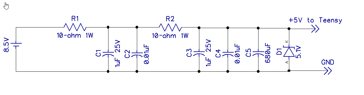
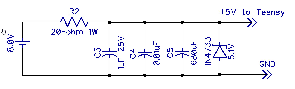
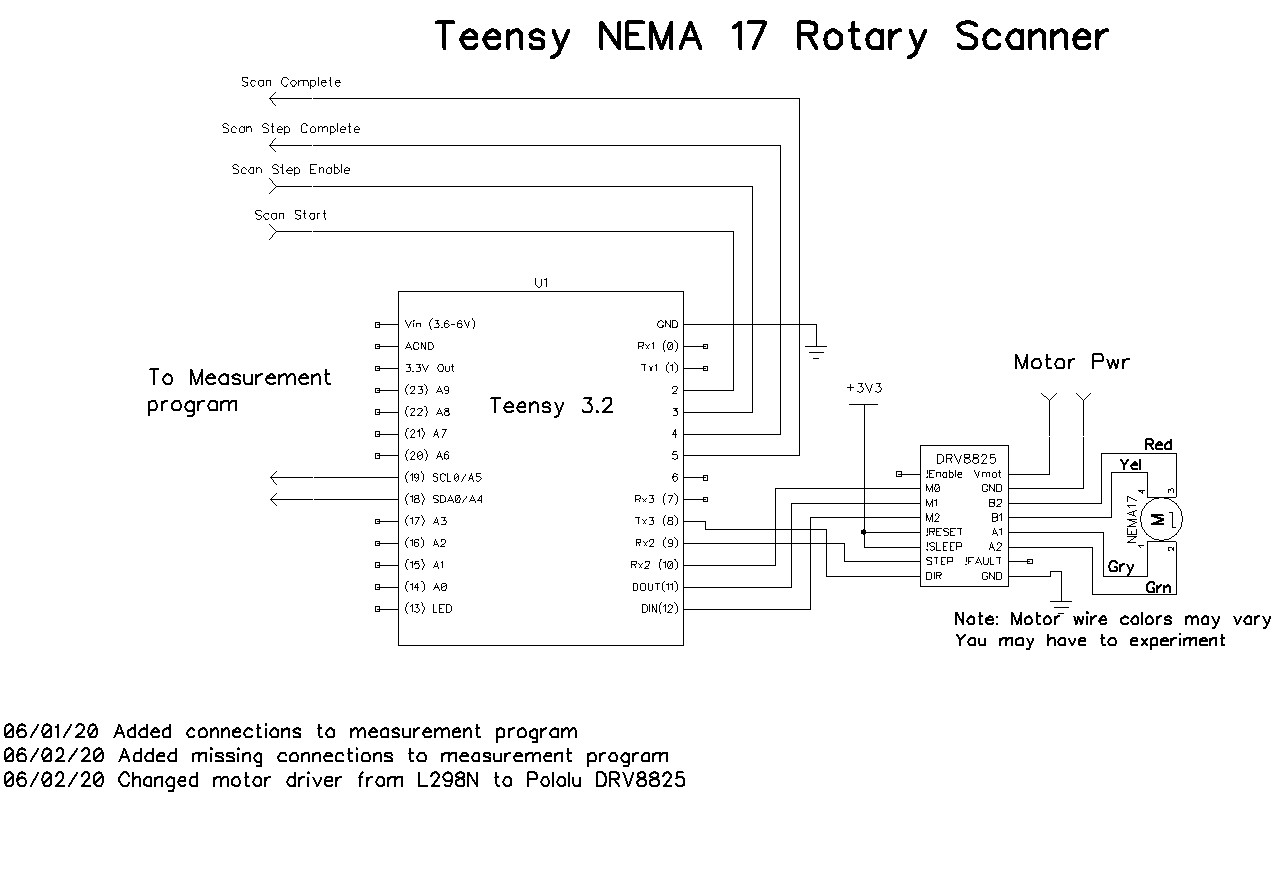
Here’s the wiring diagram:
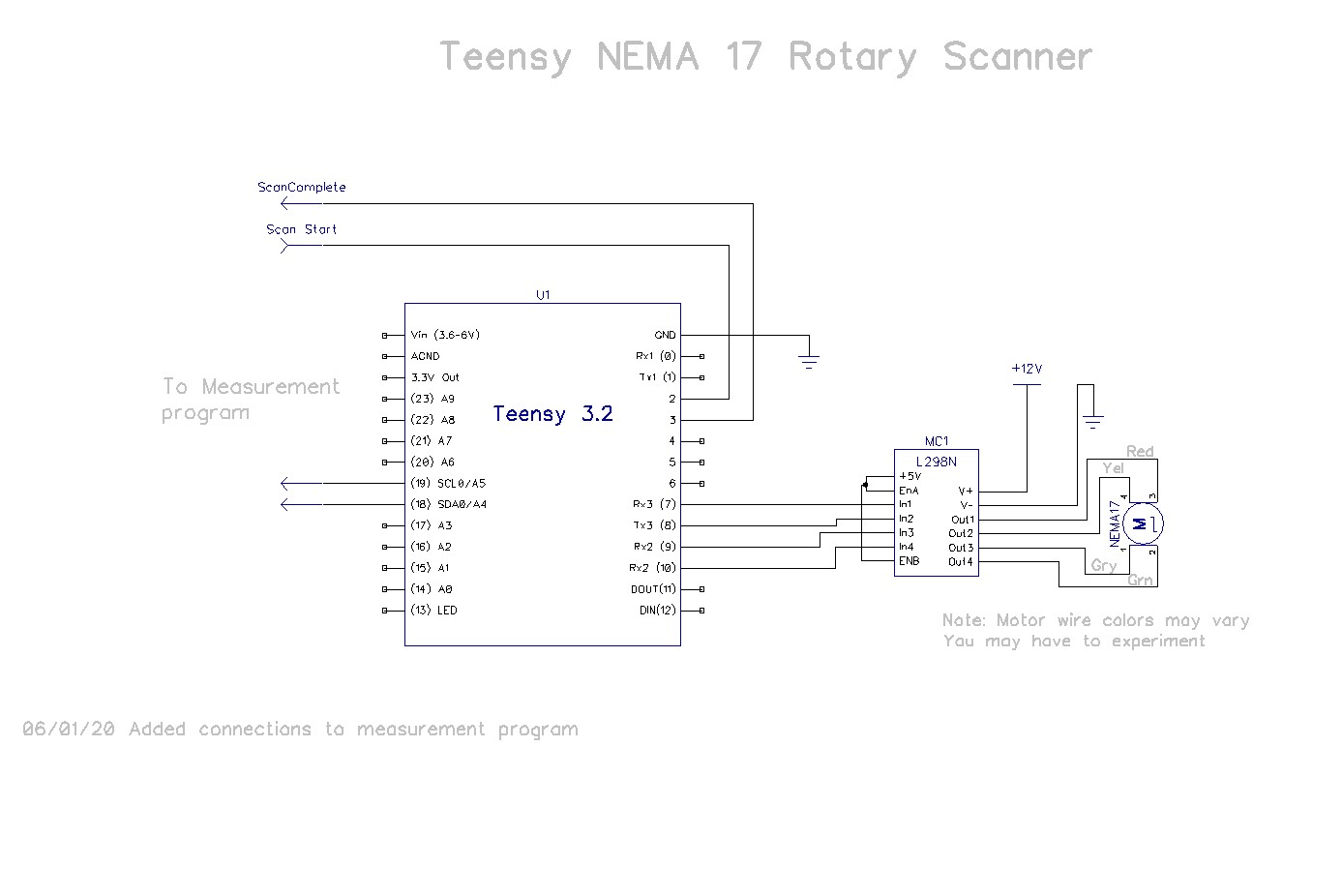
Wiring diagram for Rotary Table program
And the software
|
1 2 3 4 5 6 7 8 9 10 11 12 13 14 15 16 17 18 19 20 21 22 23 24 25 26 27 28 29 30 31 32 33 34 35 36 37 38 39 40 41 42 43 44 45 46 47 48 49 50 51 52 53 54 55 56 57 58 59 60 61 62 63 64 65 66 67 68 69 70 71 72 73 74 75 76 77 78 79 80 81 82 83 84 85 86 87 88 89 90 91 92 93 94 95 96 97 98 99 100 101 102 103 104 105 106 107 108 109 110 111 112 113 114 115 116 117 118 119 120 121 122 123 124 125 126 127 128 129 130 131 132 133 134 135 136 137 138 139 140 141 142 143 144 145 146 147 148 149 150 151 152 153 154 155 156 157 158 159 160 161 162 163 164 165 166 167 168 169 170 171 172 173 174 175 176 177 178 179 180 181 182 183 184 185 186 187 188 189 190 191 192 193 194 195 196 197 198 199 200 201 202 203 204 205 206 207 208 209 210 211 212 213 214 215 216 217 218 219 220 221 222 223 224 225 226 227 228 229 230 231 232 233 234 235 236 237 238 239 240 241 242 243 244 245 246 247 248 249 250 251 252 253 254 255 256 257 258 259 260 261 262 263 264 265 266 267 268 269 270 271 272 273 274 275 276 277 278 279 280 281 282 283 284 285 286 287 288 289 290 291 292 293 294 295 296 297 298 299 300 301 302 303 304 305 306 307 308 309 310 311 312 313 314 315 316 317 318 319 |
/* Name: Teensy_NEMA17_L298N_RotaryTable.ino Created: 5/27/2020 11:00:40 AM Author: FRANKNEWXPS15\Frank */ /* Teensy NEMA 17 L298N Rotary Table Program This program controls a NEMA 17 stepper motor using an L298N motor driver. It Takes user input to define the boresight (zero) position and the start and stop angles in degrees relative to the zero position. Then it moves to the start position and waits for a HIGH level on SCAN_START_PIN. After this signal is received, the motor is stepped through to the stop position. At the stop position, the SCAN_COMPLETE_PIN is driven HIGH. The Stepper motor is connected to an L298N motor driver with one coil on Out1/2, and the other coil on Out3/4. It may turn out that one coil's leads have to be reversed to match the motor rotation direction with the program direction. The Teensy 3.2 is connect to In1/2/3/4 via pins 8,9,10,11 although this can be changed in the constructor below. The NEMA 17 motor is assumed to execute 200 steps/revolution. Change the StepsPerRevolution constant for other values. 05/27/20: Performs an angular scan over user-supplied range of angles. By default a complete scan from start position to stop position is performed, followed by a return to the start position However, if the STEP_ENABLE_PIN (held HIGH by default) is pulled LOW, the program will wait until it goes HIGH before performing the next step. In this case, a scan iteration would go as follows Step 1 - Scan paramaters entered, motor moves to start position, waits for LOW on SCAN_START_PIN Step 2 - Measurement program pulls SCAN_START_PIN LOW for 1 sec, then back HIGH Step 3 - Measurement program takes a measurement & retrieves step# & angle value via I2C request Step 4 - Measurement program pulls SCAN_STEP_ENABLE_PIN LOW Step 5 - Motor moves to first/next step, and outputs HIGH on SCAN_STEP_COMPLETE_PIN Step 6 - Measurement program waits for HIGH on SCAN_STEP_COMPLETE_PIN Step 7 - Measurement program takes a measurement & retrieves step# & angle value via I2C request Step 8 - Repeat Steps 4-7 until scan complete Step 9 - SCAN_COMPLETE_PIN goes HIGH */ //O5/30/20 Added I2C connection to pass step# & relative angle values to measurement program #include <Stepper.h> #include <Wire.h> #include "I2C_Anything.h" // change this to fit the number of steps per revolution for your motor const int stepsPerRevolution = 200; // initialize the stepper library on pins 8 through 11: Stepper myStepper(stepsPerRevolution, 8, 9, 10, 11); //08/26/17 added for scan support const int SCAN_START_PIN = 2; const int SCAN_STEP_ENABLE_PIN = 3; const int SCAN_STEP_COMPLETE_PIN = 4; const int SCAN_COMPLETE_PIN = 5; const float MOTOR_STEPS_PER_REV = 200; const float MOTOR_STEPS_PER_DEG = MOTOR_STEPS_PER_REV / 360; const float DEG_PER_MOTOR_STEP = 360/MOTOR_STEPS_PER_REV; //added 05/30/20 const int DEFAULT_MOTOR_STEPS_TO_MOVE = 10; char Instr[20]; //const int POSITIONING_SPEED_RPM = 20; const int POSITIONING_SPEED_RPM = 100; int zeroPos; int scanStartDeg; int scanStartSteps; //scanStartDeg converted to steps int scanStopDeg; int scanStopSteps; //scanStopDeg converted to steps int scanNumberofSteps; //added 05/27/20 int stepsToMove; //steps to move to initial position int curMotorStepVal; //keeps track of current position, in steps float curRelPointingAngleDeg; //keeps track of current relative pointing angle, in degrees int curAngleStepVal; //keeps track of current table step iteration value bool bStopPosDone = false; int scanSpeedRpm = 6; const int SLAVE_ADDR = 8; //added 05/30/20 void setup() { //added 05/30/20 to provide step# & angle values to Angle Scan program Wire.begin(SLAVE_ADDR); Wire.setSCL(18); Wire.setSCL(19); Wire.setClock(100000); Wire.onRequest(requestEvent); Serial.begin(115200); unsigned long now = millis(); while (!Serial) { delay(10); } delay(5000); //05/28/20 delay AFTER Serial object instantiation is NECESSARY! Serial.print("Serial available after "); Serial.print(millis() - now); Serial.print(" millisec"); pinMode(SCAN_START_PIN, INPUT_PULLUP); pinMode(SCAN_STEP_ENABLE_PIN, INPUT_PULLUP); pinMode(SCAN_STEP_COMPLETE_PIN, OUTPUT); pinMode(SCAN_COMPLETE_PIN, OUTPUT); //init SCAN_COMPLETE_PIN, SCAN_STEP_COMPLETE to LOW (not complete) state digitalWrite(SCAN_COMPLETE_PIN, LOW); digitalWrite(SCAN_STEP_COMPLETE_PIN, LOW); //added 05/26/20 Serial.printf("Serial.printf: NEMA-17 Stepper Rotary Table Program\n"); //get motor speed to be used scanSpeedRpm = GetIntegerParameter("Motor speed RPM", 6); myStepper.setSpeed(scanSpeedRpm); //set zero position Serial.println("Set stepper zero position. Enter +steps for CW, -steps for CCW, Q to exit"); while (!bStopPosDone) { while (Serial.available() == 0); //waits for input if (toascii(Serial.peek()) == 'Q' || toascii(Serial.peek()) == 'q') { bStopPosDone = true; curMotorStepVal = 0; } else { stepsToMove = GetIntegerParameter("Steps to move (- = CCW, + = CW)?", DEFAULT_MOTOR_STEPS_TO_MOVE); Serial.print("Steps to move = "); Serial.println(stepsToMove); myStepper.setSpeed(POSITIONING_SPEED_RPM); myStepper.step(stepsToMove); } } Serial.readString(); //clear the input buffer - could still have chars in it Serial.print("curMotorStepVal = "); Serial.println(curMotorStepVal); //set scan start/stop positions in degrees scanStartDeg = GetIntegerParameter("Scan Start Pos in Degrees Relative to Zero", -90); scanStopDeg = GetIntegerParameter("Scan Stop Pos in Degrees Relative to Zero", 90); scanNumberofSteps = GetIntegerParameter("Number of Steps", 18); curRelPointingAngleDeg = scanStartDeg; //added 05/30/20 Serial.println("Run Parameters:"); Serial.print("Speed: "); Serial.print(scanSpeedRpm); Serial.println(" RPM"); Serial.print("Scan Start: "); Serial.print(scanStartDeg); Serial.println(" Deg"); Serial.print("Scan Stop: "); Serial.print(scanStopDeg); Serial.println(" Deg"); Serial.print("Scan Steps: "); Serial.println(scanNumberofSteps); Serial.println(); //go to scan start pos scanStartSteps = (int)scanStartDeg * MOTOR_STEPS_PER_DEG; Serial.print("steps to move = "); Serial.println(scanStartSteps); Serial.printf("Before move, curMotorStepVal = %d, scanStartSteps = %d\n", curMotorStepVal, scanStartSteps); myStepper.step(scanStartSteps); curMotorStepVal += scanStartSteps; Serial.print("Done - curMotorStepVal = "); Serial.println(curMotorStepVal); Serial.printf("After move, curMotorStepVal = %d, scanStartSteps = %d\n", curMotorStepVal, scanStartSteps); int motorStepsPerScanStep = (int)(((int)scanStopDeg * MOTOR_STEPS_PER_DEG - curMotorStepVal) / (float)scanNumberofSteps); //05/27/20 Serial.print("Motor Steps Per Scan Step = "); Serial.println(motorStepsPerScanStep); while (1) //user has opportunity to exit after each scan { //wait for trigger Serial.printf("waiting for LOW on SCAN_START_PIN (pin %d) ...\n", SCAN_START_PIN); while (digitalRead(SCAN_START_PIN) == HIGH) { delay(100); } Serial.println("Scan Triggered - starting scan, setting SCAN_COMPLETE_PIN to LOW\n"); digitalWrite(SCAN_COMPLETE_PIN, LOW); //for (curAngleStepVal = 0; curAngleStepVal < scanNumberofSteps; curAngleStepVal++) for (curAngleStepVal = 0; curAngleStepVal <= scanNumberofSteps; curAngleStepVal++) { curRelPointingAngleDeg = curAngleStepVal * motorStepsPerScanStep * DEG_PER_MOTOR_STEP; //added 05/30/20 //when SCAN_STEP_ENABLE_PIN goes LOW, go to first/next step. while (digitalRead(SCAN_STEP_ENABLE_PIN)) { } unsigned long now = millis(); digitalWrite(SCAN_STEP_COMPLETE_PIN, LOW); Serial.printf("Scan Step %d Triggered: motor steps to move = %d\n", curAngleStepVal, motorStepsPerScanStep); myStepper.setSpeed(scanSpeedRpm); myStepper.step(motorStepsPerScanStep); curMotorStepVal += motorStepsPerScanStep; Serial.printf("Done in %lu Msec - curMotorStepVal = %d\n", millis() - now, curMotorStepVal); //delay(200); //output HIGH on SCAN_STEP_COMPLETE_PIN Serial.printf("Outputting HIGH on SCAN_STEP_COMPLETE_PIN\n"); digitalWrite(SCAN_STEP_COMPLETE_PIN, HIGH); //delay(50); //make the HIGH period visible on scope } //quit Serial.printf("Outputting HIGH on SCAN_COMPLETE_PIN (pin %d)\n", SCAN_COMPLETE_PIN); digitalWrite(SCAN_COMPLETE_PIN, HIGH); //return to start position stepsToMove = curMotorStepVal - scanStartSteps; Serial.println("Resetting for next scan."); Serial.printf("Before move, curMotorStepVal = %d, scanStartSteps = %d, steps to move = %d\n", curMotorStepVal, scanStartSteps, stepsToMove); myStepper.setSpeed(POSITIONING_SPEED_RPM); myStepper.step(-stepsToMove); curMotorStepVal = scanStartSteps; Serial.print("Done - curMotorStepVal = "); Serial.println(curMotorStepVal); myStepper.setSpeed(scanSpeedRpm); Serial.printf("Enter any key to continue\n"); while (!Serial.available()) { } //consume bytes until Serial buffer is empty to avoid unintended triggers int incomingByte; while (Serial.available()) { incomingByte = Serial.read(); Serial.printf("Consuming 0x%x\n", incomingByte); } } } void loop() { } int GetIntegerParameter(String prompt, int defaultval) { int param = 0; bool bDone = false; while (!bDone) { Serial.print(prompt); Serial.print(" ("); Serial.print(defaultval); Serial.print("): "); while (Serial.available() == 0); //waits for input //String res = Serial.readString().trim(); String res = Serial.readString(); res.trim(); int reslen = res.length(); if (reslen == 0) //user entered CR only { bDone = true; param = defaultval; } else { res.toCharArray(Instr, reslen + 1); //if (isNumeric(Instr) && atoi(Instr) >= 0) if (isNumeric(Instr)) { param = atoi(Instr); bDone = true; } else { Serial.print(Instr); Serial.println(" Is invalid input - please try again"); } } } Serial.println(param); return param; } // check a string to see if it is numeric and accept Decimal point //copied from defragster's post at https://forum.pjrc.com/threads/27842-testing-if-a-string-is-numeric bool isNumeric(char* str) { byte ii = 0; bool RetVal = false; if ('-' == str[ii]) ii++; while (str[ii]) { if ('.' == str[ii]) { ii++; break; } if (!isdigit(str[ii])) return false; ii++; RetVal = true; } while (str[ii]) { if (!isdigit(str[ii])) return false; ii++; RetVal = true; } return RetVal; } //05/30/20 added to report current angle step# & relative pointing angle to measurement program void requestEvent() { //send the current step# and current relative pointing angle Serial.printf("In requestEvent: curAngleStep = %d, curRelAngle = %2.2f\n", curAngleStepVal, curAngleStepVal, curRelPointingAngleDeg, curRelPointingAngleDeg); I2C_writeAnything(curAngleStepVal); I2C_writeAnything(curRelPointingAngleDeg); } |
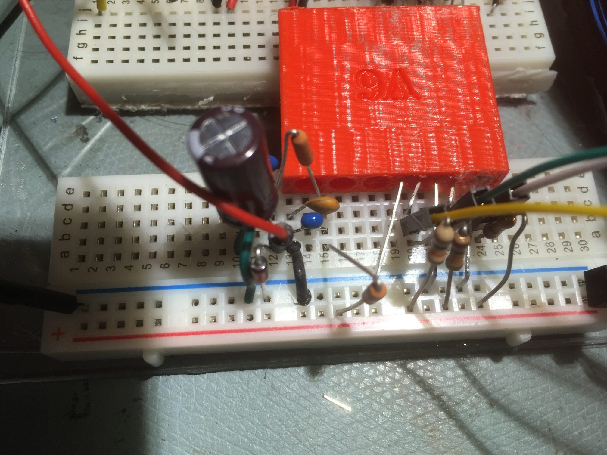
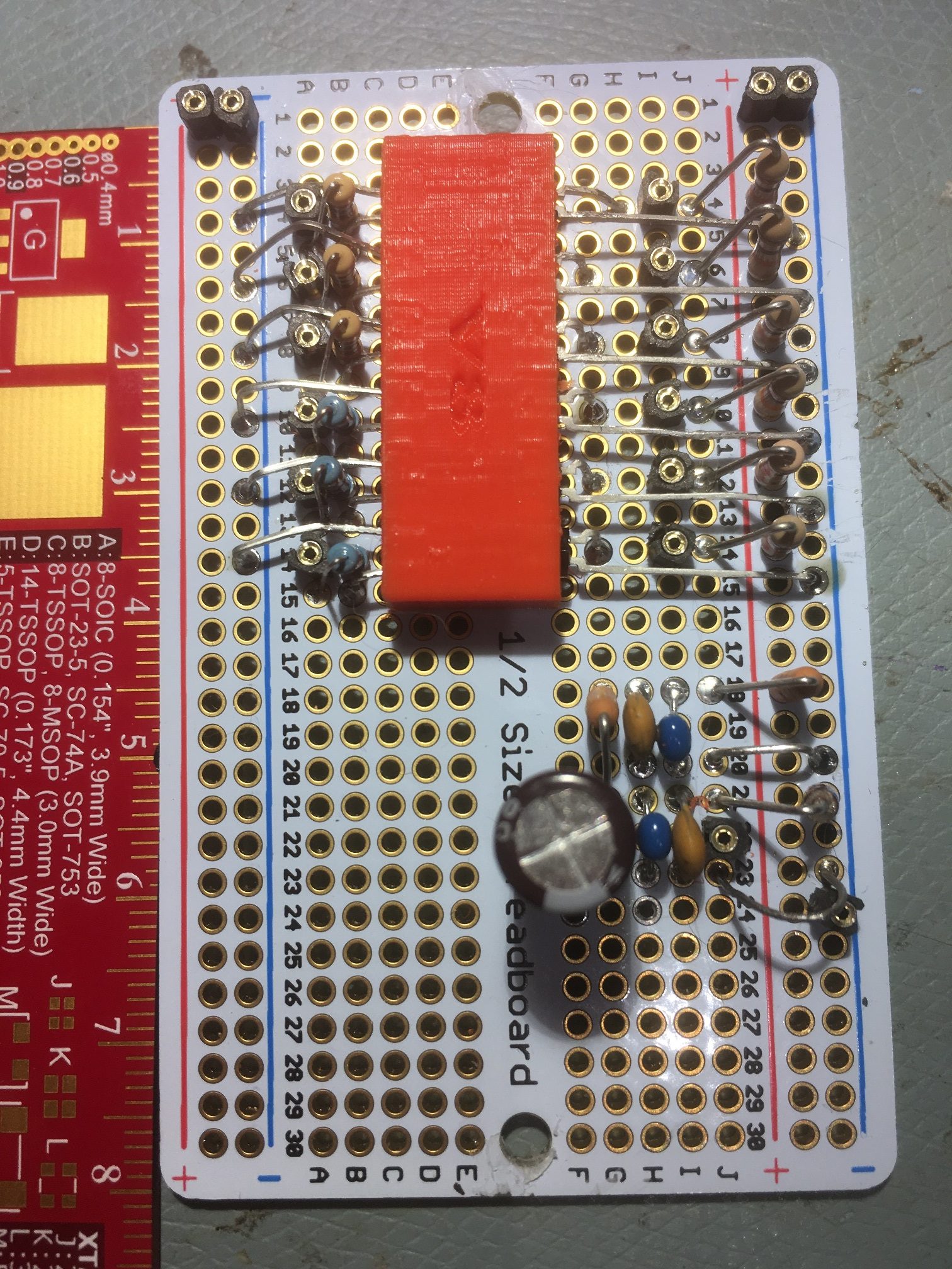
And the hardware layout:
I couldn’t find any information about winding polarity for this particular NEMA 17 stepper, so it was sort of a crapshoot as to which way the motor was going to turn for a nominal CW or CCW input to the program. As it turned out, I had to reverse one set of wires on the L298N to get the stepper to turn in the correct direction.
Companion Measurement System
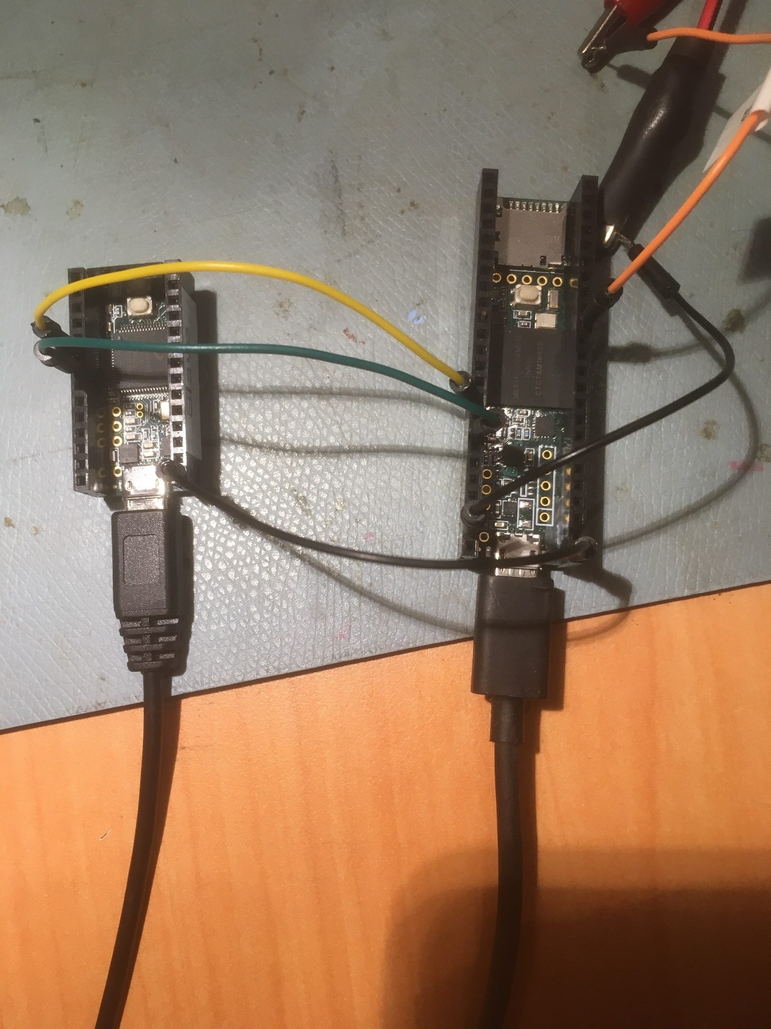
For the companion measurement system, I used a Teensy 3.5 micro-controller, as I needed to connect to the VL53L0X ‘Time of Flight’ sensors and the Rotary Table program/micro-controller via I2C, and The Teensy 3.5 has provisions for up to three separate I2C busses (Wire, Wire1 & Wire2). Although it would be possible to put everything on one I2C bus, I wanted to isolate the two ‘sides’ (the rotary table control side, and the sensor control side). This dual-IC2 bus arrangement is also the way I plan to integrate the VL53L0X sensor arrays into Wall-E2, my autonomous wall-following robot, so this will give me a chance to work out the bugs on a smaller scale.
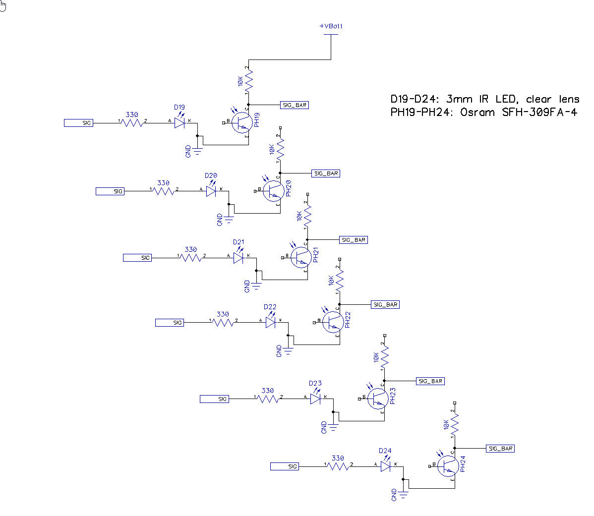
Here’s the wiring diagram:
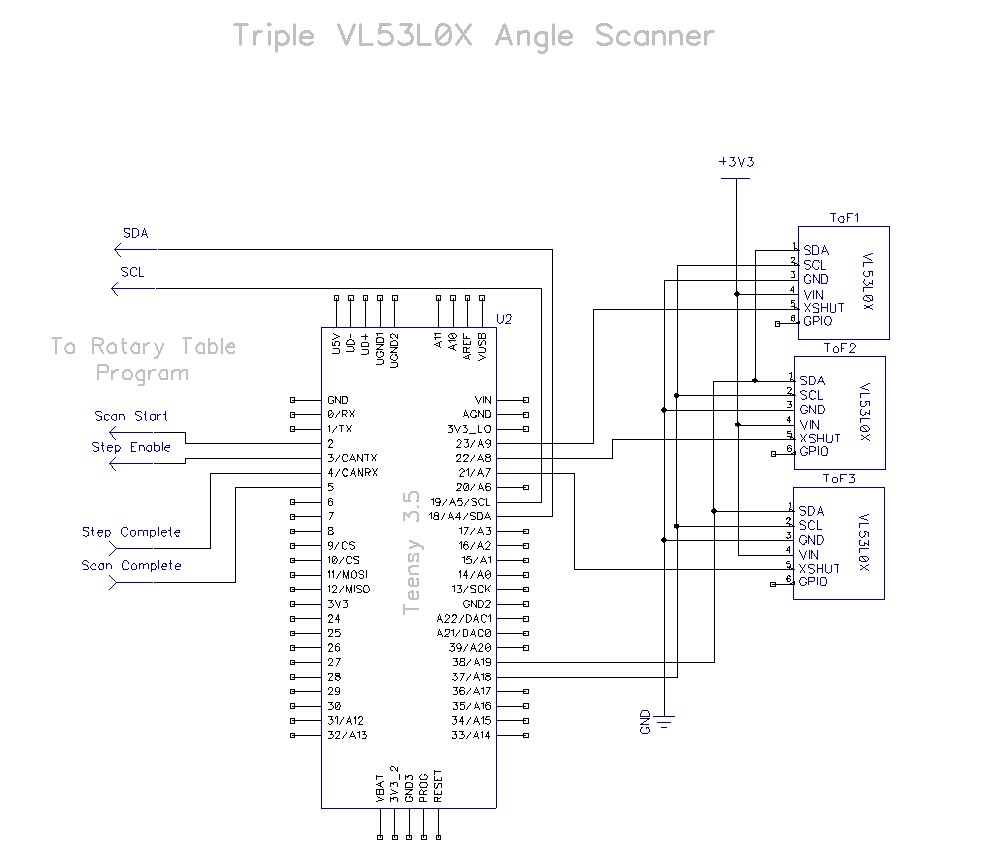
Wiring diagram for the companion measurement system, with triple VL53L0X ToF sensors
And the software:
|
1 2 3 4 5 6 7 8 9 10 11 12 13 14 15 16 17 18 19 20 21 22 23 24 25 26 27 28 29 30 31 32 33 34 35 36 37 38 39 40 41 42 43 44 45 46 47 48 49 50 51 52 53 54 55 56 57 58 59 60 61 62 63 64 65 66 67 68 69 70 71 72 73 74 75 76 77 78 79 80 81 82 83 84 85 86 87 88 89 90 91 92 93 94 95 96 97 98 99 100 101 102 103 104 105 106 107 108 109 110 111 112 113 114 115 116 117 118 119 120 121 122 123 124 125 126 127 128 129 130 131 132 133 134 135 136 137 138 139 140 141 142 143 144 145 146 147 148 149 150 151 152 153 154 155 156 157 158 159 160 161 162 163 164 165 166 167 168 169 170 171 172 173 174 175 176 177 178 179 180 181 182 183 184 185 186 187 188 189 190 191 192 193 194 195 196 197 198 199 200 201 202 203 204 205 206 207 208 209 210 211 212 213 214 215 216 217 218 219 220 221 222 223 224 225 226 227 228 229 230 231 232 233 234 235 236 237 238 239 240 241 242 243 244 245 246 247 248 249 250 251 252 253 254 255 256 257 258 259 260 261 262 263 264 265 266 267 268 269 270 271 272 273 274 275 276 277 278 279 280 281 282 283 284 285 286 287 288 289 290 291 292 293 294 295 296 297 298 299 300 301 302 303 304 305 306 307 308 309 310 311 312 313 314 315 316 317 318 319 320 321 322 323 324 325 |
/* Name: TeensyTripleVL53L0XAngleScanV1.ino Created: 5/28/2020 12:15:50 PM Author: FRANKNEWXPS15\Frank */ /* This program is derived from Teensy_Triple_VL53L0X_V2.ino. It uses the Teensy_NEMA17_L298N_RotaryTable program to perform triple VL53L0X measurements over a range of angles. Teensy_NEMA17_L298N_RotaryTable program: Performs an angular scan over user-supplied range of angles. By default a complete scan from start position to stop position is performed, followed by a return to the start position However, if the STEP_ENABLE_PIN (held HIGH by default) is pulled LOW, the program will wait until it goes HIGH before performing the next step. In this case, a scan iteration would go as follows Step 1 - Scan paramaters entered, motor moves to start position, waits for LOW on SCAN_START_PIN Step 2 - Measurement program pulls SCAN_START_PIN LOW for 1 sec, then back HIGH Step 3 - Measurement program takes a measurement & retrieves step# & angle value via I2C request Step 4 - Measurement program pulls SCAN_STEP_ENABLE_PIN LOW Step 5 - Motor moves to first/next step, and outputs HIGH on SCAN_STEP_COMPLETE_PIN Step 6 - Measurement program waits for HIGH on SCAN_STEP_COMPLETE_PIN Step 7 - Measurement program takes a measurement & retrieves step# & angle value via I2C request Step 8 - Repeat Steps 4-7 until scan complete Step 9 - SCAN_COMPLETE_PIN goes HIGH At present (05/28/20) the rotary table pin assignments are: SCAN_START_PIN = 2 SCAN_STEP_ENABLE_PIN = 3 SCAN_STEP_COMPLETE_PIN = 4 SCAN_COMPLETE_PIN = 5 */ /* This code copied from the following post on the Adafruit forum: https://forums.adafruit.com/viewtopic.php?f=19&t=164589&p=808693&hilit=vl53l0x#p808693 And adapted to use it on the Wire1 I2C bus on a Teensy 3.5 */ #include <Wire.h> #include "Adafruit_VL53L0X.h" #include "I2C_Anything.h" Adafruit_VL53L0X lidar_RF = Adafruit_VL53L0X(); //Right-front LIDAR (angled 30 deg forward) Adafruit_VL53L0X lidar_RC = Adafruit_VL53L0X(); //Center LIDAR Adafruit_VL53L0X lidar_RR = Adafruit_VL53L0X(); //Right-rear LIDAR (angled 30 deg rearward) //XSHUT required for I2C address init const int RF_XSHUT_PIN = 23; const int RC_XSHUT_PIN = 22; const int RR_XSHUT_PIN = 21; const int RED_LASER_PIN = 0; const int MAX_LIDAR_RANGE_MM = 1000; //make it obvious when nearest object is out of range uint16_t RF_Dist_mm; uint16_t RC_Dist_mm; uint16_t RR_Dist_mm; float SteeringVal; //mvd here 05/30/20 //Rotary Scan Table Connections: const int SCAN_START_PIN = 2; //connect to table SCAN_START_PIN const int SCAN_STEP_ENABLE_PIN = 3;//connect to table SCAN_STEP_ENABLE_PIN const int SCAN_STEP_COMPLETE_PIN = 4;//connect to table SCAN_STEP_COMPLETE_PIN const int SCAN_COMPLETE_PIN = 5;//connect to table SCAN_COMPLETE_PIN //added 05/30/20 to retrieve values from rotary table program const int SLAVE_ADDR = 8; int curStepVal = 0; float curAngleDeg = 0; void setup() { //added 05/30/20 to retrieve step# & angle values from rotary table program Wire.begin(); Wire.setClock(100000); Wire.setSCL(18); Wire.setSDA(19); Serial.begin(115200); //Teensy ignores rate parameter // wait until serial port opens for native USB devices while (!Serial) { delay(1); } delay(5000); //05/28/20 - this delay is necessary AFTER Serial instantiation! Serial.printf("Teensy Triple VL53L0X Angle Scan Program\n"); pinMode(RF_XSHUT_PIN, OUTPUT); pinMode(RC_XSHUT_PIN, OUTPUT); pinMode(RR_XSHUT_PIN, OUTPUT); pinMode(RED_LASER_PIN, OUTPUT); //Rotary Scan Table Connections: pinMode(SCAN_START_PIN, OUTPUT); pinMode(SCAN_STEP_ENABLE_PIN, OUTPUT); pinMode(SCAN_STEP_COMPLETE_PIN, INPUT_PULLDOWN); pinMode(SCAN_COMPLETE_PIN, INPUT_PULLUP); //Initialize table connection states digitalWrite(SCAN_START_PIN, HIGH); //disables scans digitalWrite(SCAN_STEP_ENABLE_PIN, HIGH); //disables steps //initialize 3 LIDAR sensors // 1. Reset all sensors by setting all of their XSHUT pins low for delay(10), then set // all XSHUT high to bring out of reset digitalWrite(RF_XSHUT_PIN, LOW); delay(10); digitalWrite(RC_XSHUT_PIN, LOW); delay(10); digitalWrite(RR_XSHUT_PIN, LOW); delay(10); digitalWrite(RF_XSHUT_PIN, HIGH); digitalWrite(RC_XSHUT_PIN, HIGH); digitalWrite(RR_XSHUT_PIN, HIGH); // 2. Keep sensor #1 awake by keeping XSHUT pin high, and put all other sensors into // shutdown by pulling XSHUT pins low digitalWrite(RC_XSHUT_PIN, LOW); digitalWrite(RR_XSHUT_PIN, LOW); // 3. Initialize sensor #1 if (!lidar_RF.begin(VL53L0X_I2C_ADDR + 1, false, &Wire1)) { Serial.println(F("Failed to boot lidar_RF")); while (1); } // 4. Keep sensor #1 awake, and now bring sensor #2 out of reset by setting its XSHUT pin high. // 5. Initialize sensor #2 with lox.begin(new_i2c_address) Pick any number but 0x29 and whatever // you set the first sensor to digitalWrite(RC_XSHUT_PIN, HIGH); if (!lidar_RC.begin(VL53L0X_I2C_ADDR + 2, false, &Wire1)) { Serial.println(F("Failed to boot lidar_RC")); while (1); } // 6. Repeat for last sensor. digitalWrite(RR_XSHUT_PIN, HIGH); if (!lidar_RR.begin(VL53L0X_I2C_ADDR + 3, false, &Wire1)) { Serial.println(F("Failed to boot lidar_RR")); while (1); } //turn the laser OFF digitalWrite(RED_LASER_PIN, LOW); Serial.printf("\nInit complete\n \n"); Serial.printf("\nWhen the Rotary Table is set up and ready to go, send any key\n \n"); while (!Serial.available()) { Serial.printf("Nothing yet...\n"); delay(1000); } //consume bytes until Serial buffer is empty to avoid unintended triggers int incomingByte; while (Serial.available()) { incomingByte = Serial.read(); Serial.printf("Consuming 0x%x\n",incomingByte); } ////05/23/20 experiment with accessing API functions //VL53L0X_Dev_t RightFrontDevice = lidar_RF.GetDeviceHandle(); //VL53L0X_DeviceInfo_t RightFrontDeviceInfo = lidar_RF.GetDeviceInfo(); //Serial.printf("Device Info for Right Front Sensor\n"); //Serial.printf("\tName = %s\n\tType = %s\n\tProdID = %s\n\tType Number = %d\n\tMajor Rev = %d\n\tMinor Rev = %d\n \n", // RightFrontDeviceInfo.Name, RightFrontDeviceInfo.Type, // RightFrontDeviceInfo.ProductId, RightFrontDeviceInfo.ProductType, // RightFrontDeviceInfo.ProductRevisionMajor, RightFrontDeviceInfo.ProductRevisionMinor); ////get measurement timing budget? //prog_uint32_t MeasBudgetUSec; //VL53L0X_Error ApiError = VL53L0X_GetMeasurementTimingBudgetMicroSeconds(&RightFrontDevice, &MeasBudgetUSec); //Serial.printf("Right Front Measurement Budget (uSec) = %d\n", MeasBudgetUSec); //delay(1000); //Serial.printf("Changing budget from %d to %d....\n", MeasBudgetUSec, 2 * MeasBudgetUSec); //delay(1000); //MeasBudgetUSec = 2 * MeasBudgetUSec; //ApiError = VL53L0X_SetMeasurementTimingBudgetMicroSeconds(&RightFrontDevice, MeasBudgetUSec); //Serial.printf("Right Front Measurement Budget (uSec) Now = %d\n \n", MeasBudgetUSec); bool bDone = false; while (!bDone) { //init controls to 'disabled' state digitalWrite(SCAN_STEP_ENABLE_PIN, HIGH); //init to 'steps disabled' digitalWrite(SCAN_START_PIN, HIGH); //init to 'scan disabled' Serial.printf("Starting Angle Scan...\n \n"); Serial.printf("Msec\tStep#\tRelDeg\tFront\tCenter\tRear\tSteer\n"); //rev 5/30/20 to include step# & rel ptng angle //Tell the table to start the scan digitalWrite(SCAN_START_PIN, LOW); //trigger the scan delay(1000); //long enough for table to see it digitalWrite(SCAN_START_PIN, HIGH); //reset the trigger //do until the scan is complete while (!digitalRead(SCAN_COMPLETE_PIN)) { //take measurement GetVL53L0XValues(); //05/30/20 get current step# & relative pointing angle Wire.requestFrom(SLAVE_ADDR, sizeof(curStepVal) + sizeof(curAngleDeg)); I2C_readAnything(curStepVal); I2C_readAnything(curAngleDeg); Serial.printf("%lu\t%d\t%3.2f\t%d\t%d\t%d\t%3.2f\n", millis(),curStepVal,curAngleDeg, RF_Dist_mm, RC_Dist_mm, RR_Dist_mm, SteeringVal); digitalWrite(SCAN_STEP_ENABLE_PIN, LOW); //trigger table to step to next position delay(100); //give rotary table time to reset SCAN_STEP_COMPLETE_PIN state //wait for step to complete while (!digitalRead(SCAN_STEP_COMPLETE_PIN)) { //Serial.printf("Waiting for SCAN_STEP_COMPLETE_PIN to go HIGH\n"); //delay(1000); } //disable steps digitalWrite(SCAN_STEP_ENABLE_PIN, HIGH); //disable further steps delay(50); //05/31/20 give SCAN_COMPLETE_PIN a chance to go HIGH before next measurement } Serial.printf("SCAN_COMPLETE_PIN HIGH Received - Scan is Complete!\n"); Serial.printf("Enter Q to quit, anything else for another scan\n"); while (!Serial.available()) { Serial.printf("nothing yet....\n"); delay(1000); } incomingByte = Serial.read(); Serial.printf("I received: 0x%0x\n",incomingByte); if (incomingByte == 0x51 || incomingByte == 0x71) { Serial.printf("Stopping Program - Goodbye!\n"); while (true) { } } else { //consume any remaining bytes in buffer while (Serial.available() > 0) { Serial.read(); } Serial.printf("Starting another scan...\n"); } } } void loop() { } void GetVL53L0XValues() { //Serial.printf("In GetVL53L0XValues()\n"); VL53L0X_RangingMeasurementData_t measure; //turn the laser ON digitalWrite(RED_LASER_PIN, HIGH); lidar_RF.rangingTest(&measure, false); // pass in 'true' to get debug data printout! if (measure.RangeStatus != 4) // phase failures have incorrect data { RF_Dist_mm = measure.RangeMilliMeter; if (RF_Dist_mm > MAX_LIDAR_RANGE_MM) RF_Dist_mm = MAX_LIDAR_RANGE_MM; } else RF_Dist_mm = 0; lidar_RC.rangingTest(&measure, false); // pass in 'true' to get debug data printout! if (measure.RangeStatus != 4) // phase failures have incorrect data { RC_Dist_mm = measure.RangeMilliMeter; if (RC_Dist_mm > MAX_LIDAR_RANGE_MM) RC_Dist_mm = MAX_LIDAR_RANGE_MM; } else RC_Dist_mm = 0; lidar_RR.rangingTest(&measure, false); // pass in 'true' to get debug data printout! if (measure.RangeStatus != 4) // phase failures have incorrect data { RR_Dist_mm = measure.RangeMilliMeter; if (RR_Dist_mm > MAX_LIDAR_RANGE_MM) RR_Dist_mm = MAX_LIDAR_RANGE_MM; } else RR_Dist_mm = 0; SteeringVal = (RF_Dist_mm - RR_Dist_mm) / (float)RC_Dist_mm; //turn the laser OFF digitalWrite(RED_LASER_PIN, LOW); //delay(100); } |
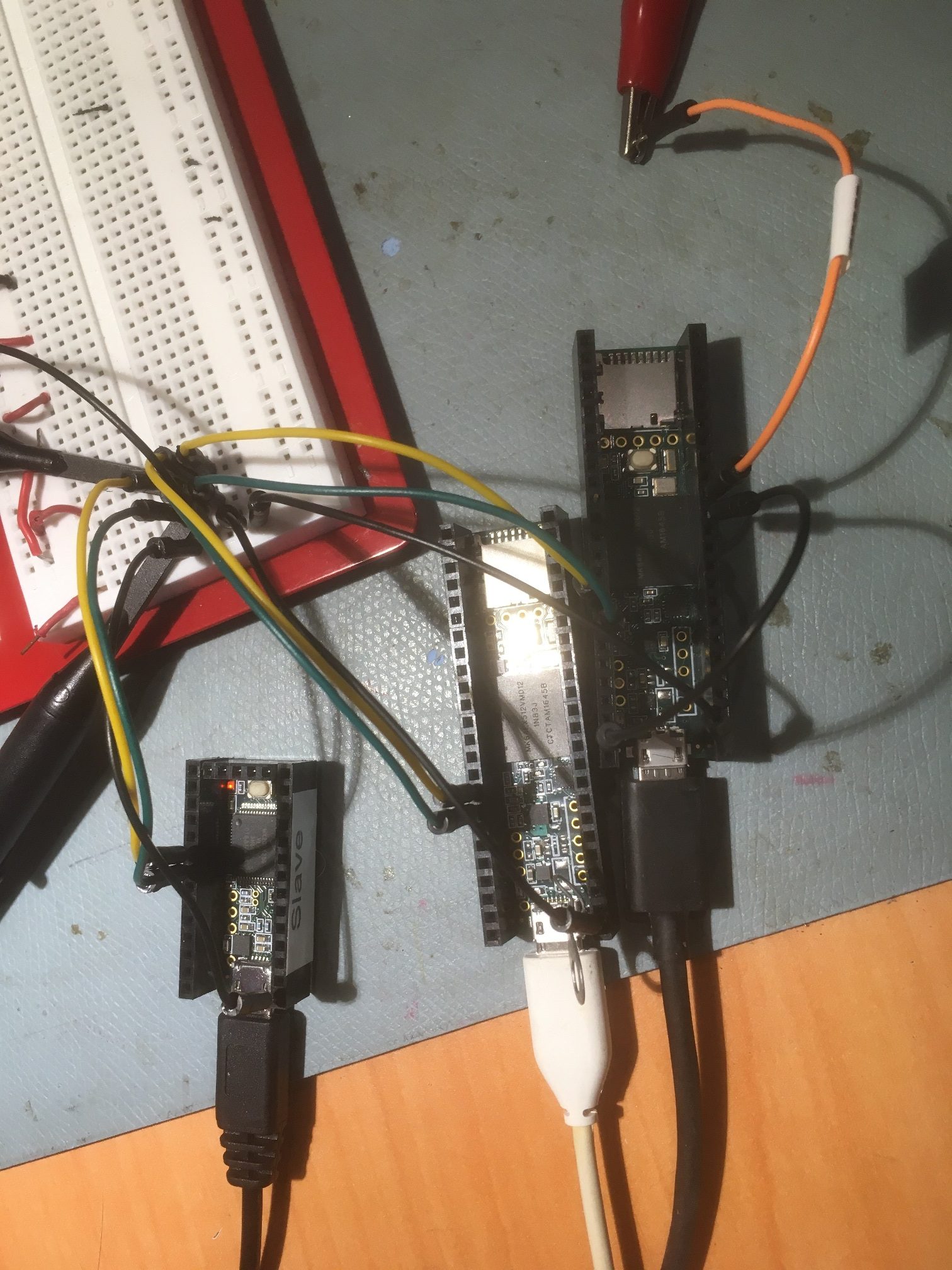
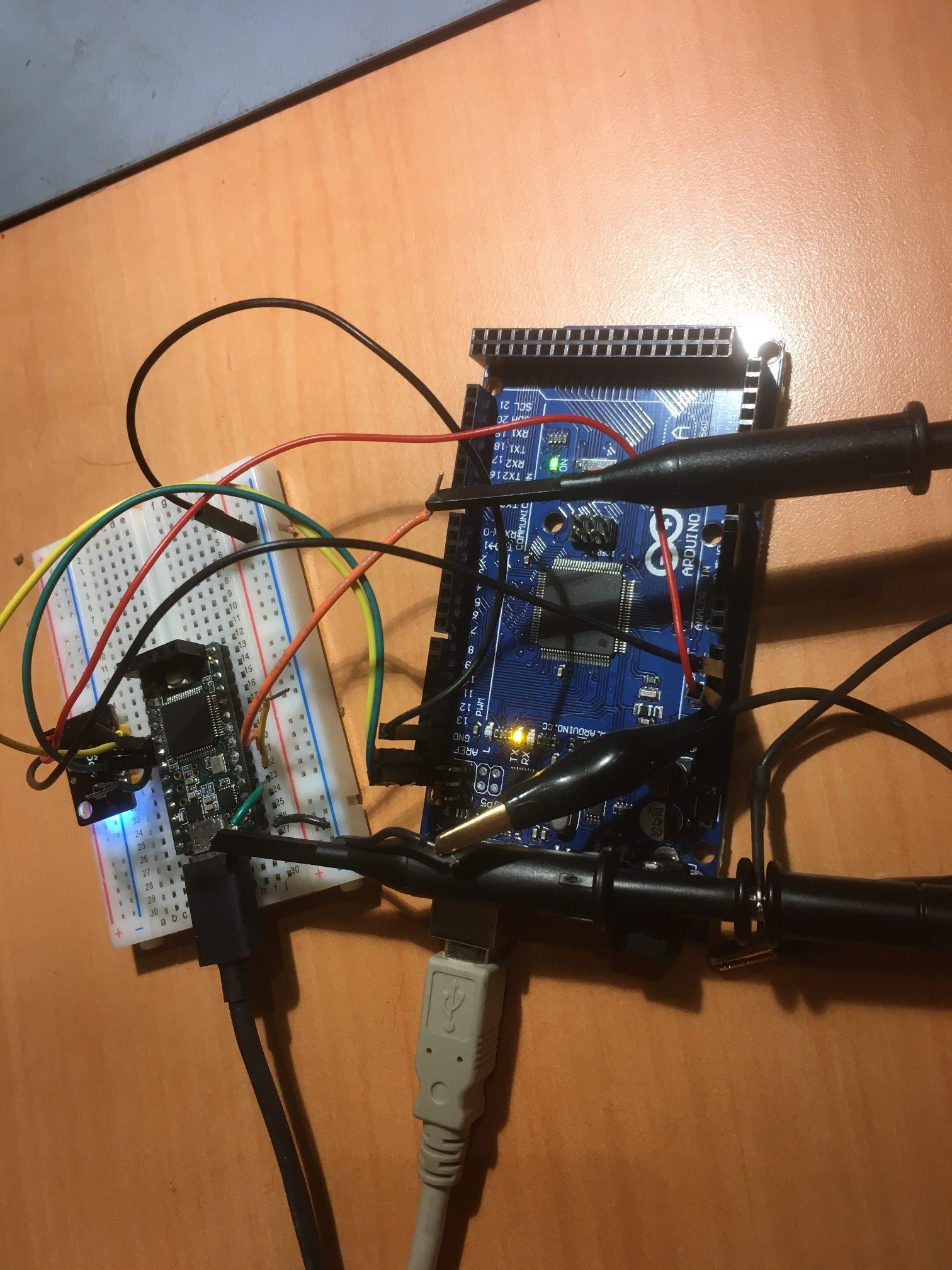
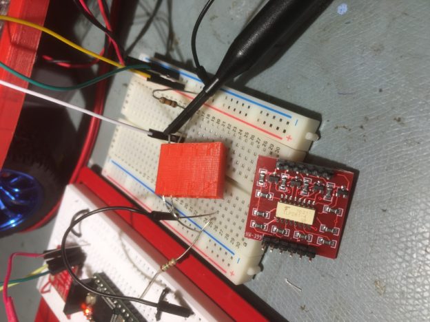
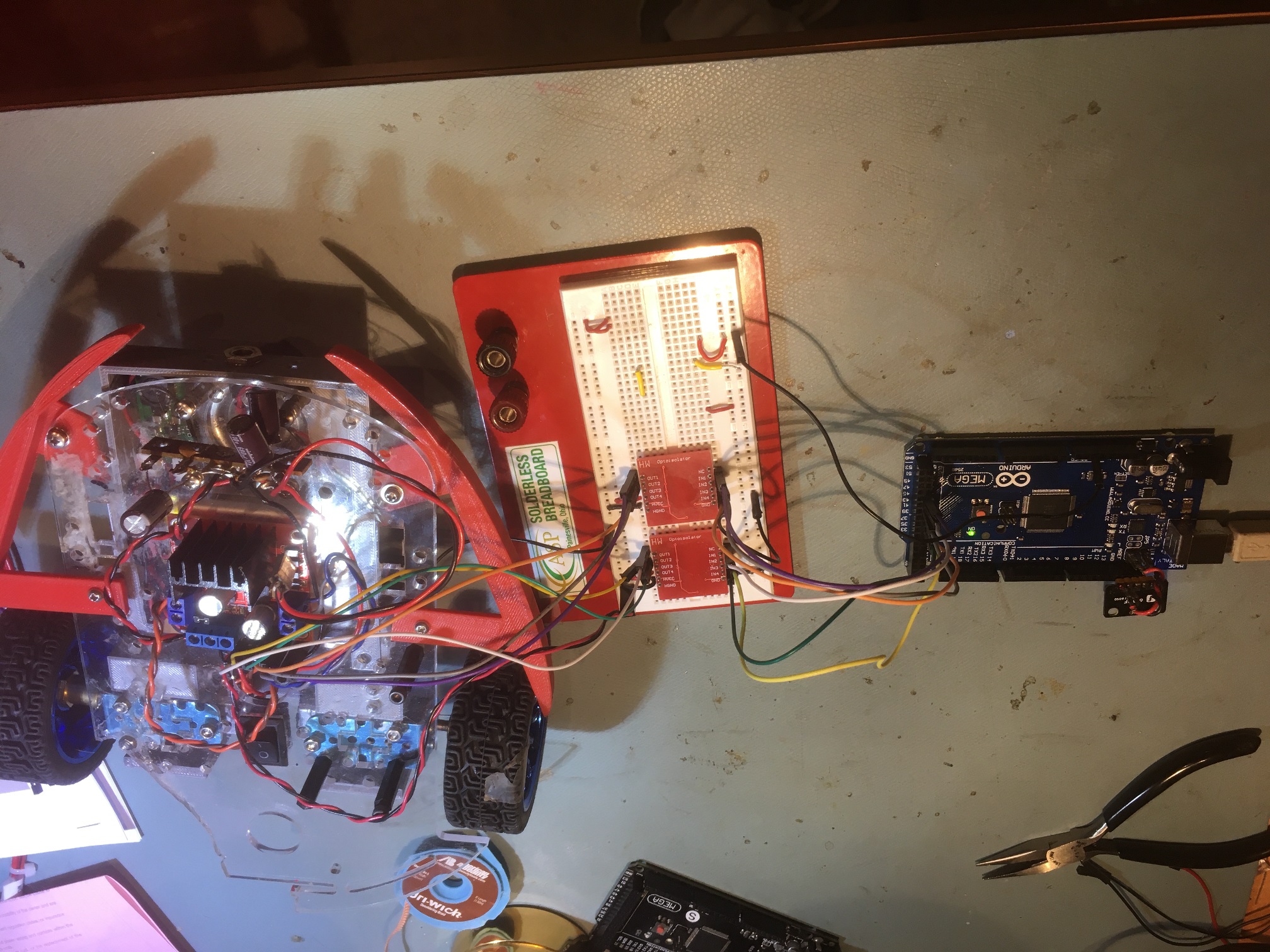
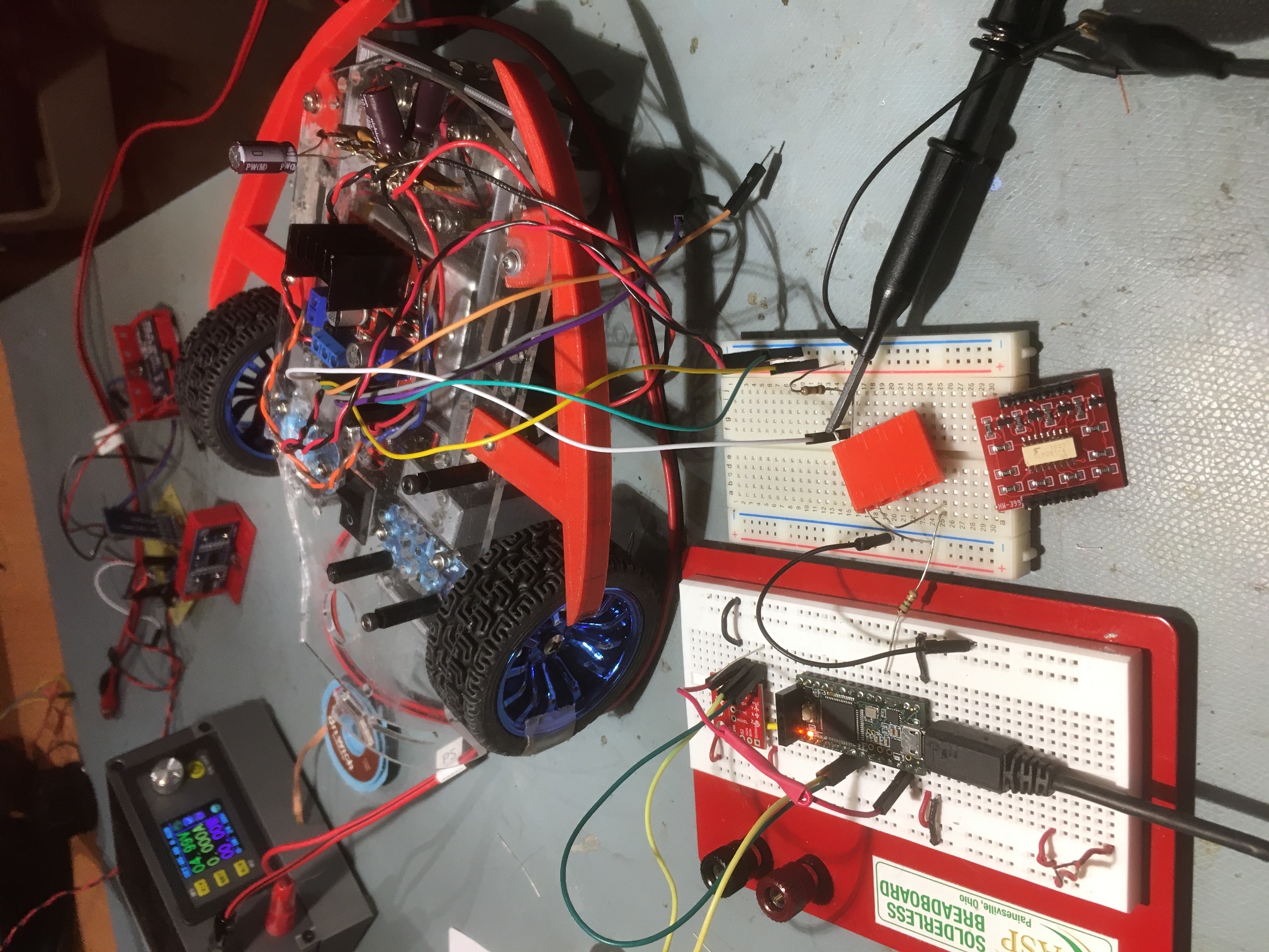
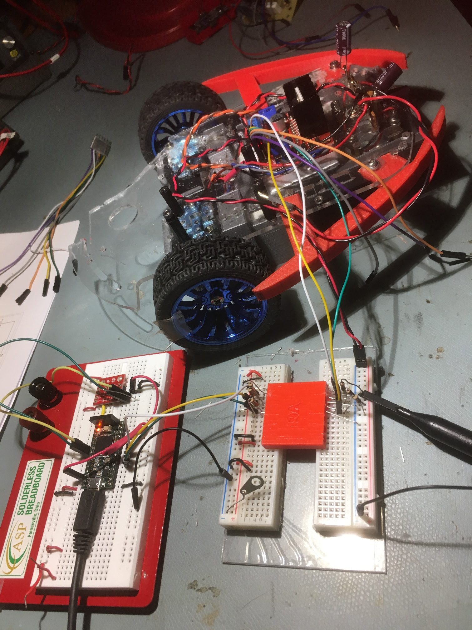
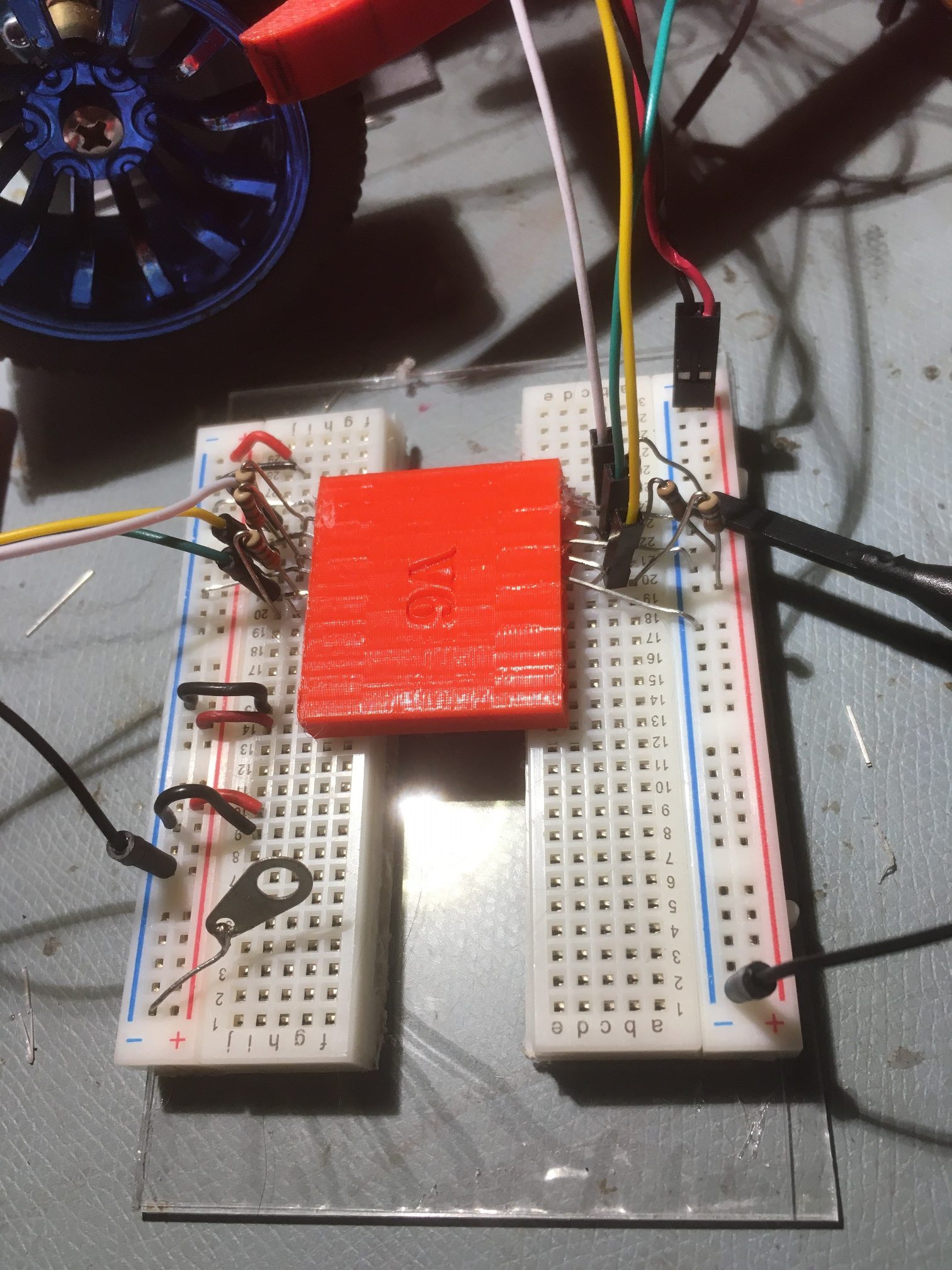
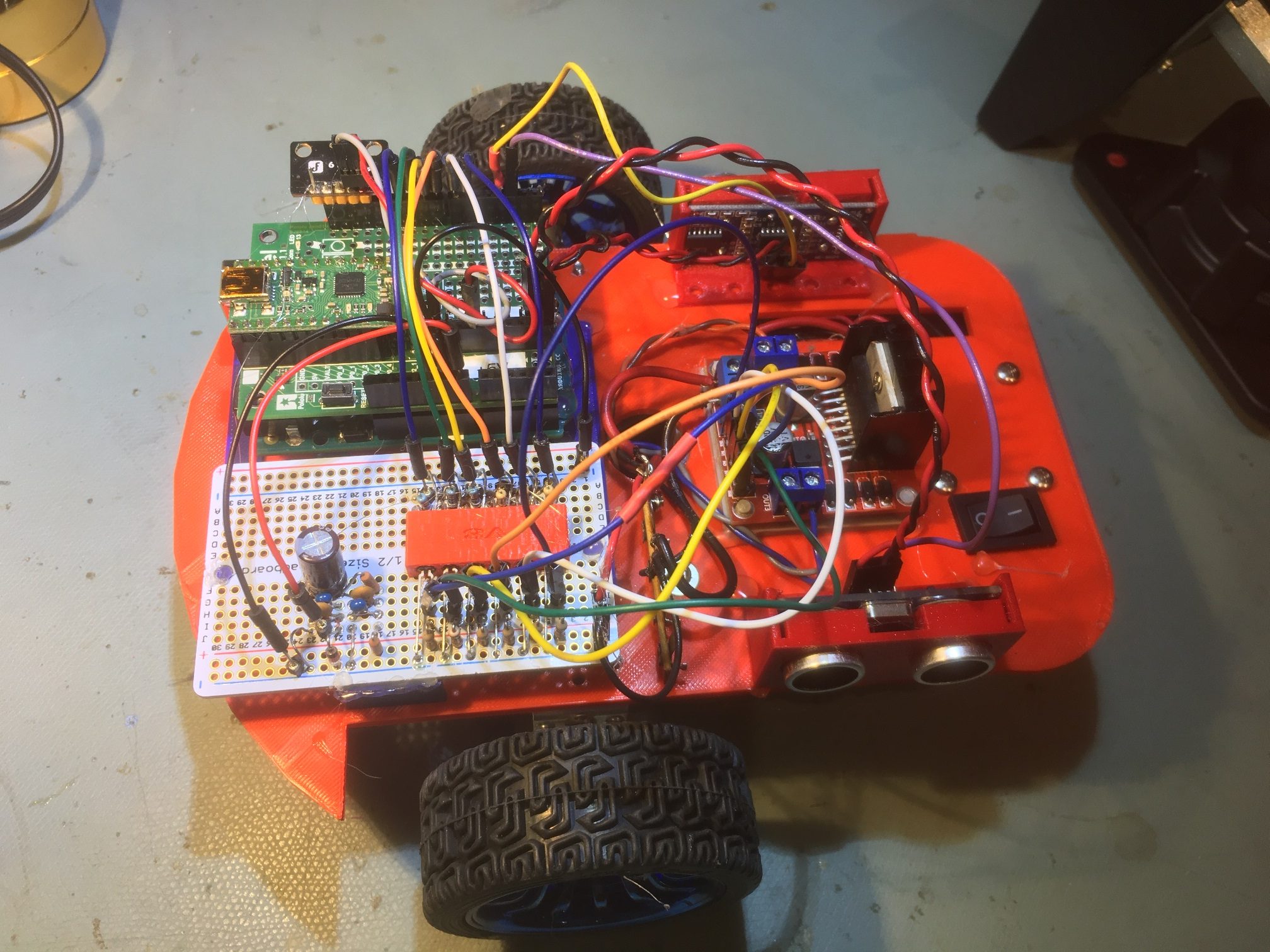
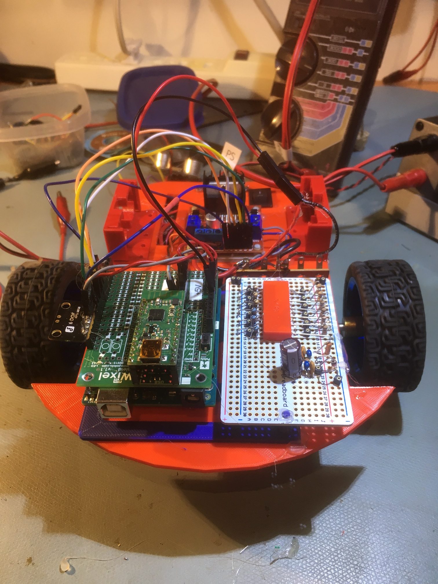
and the hardware setup:
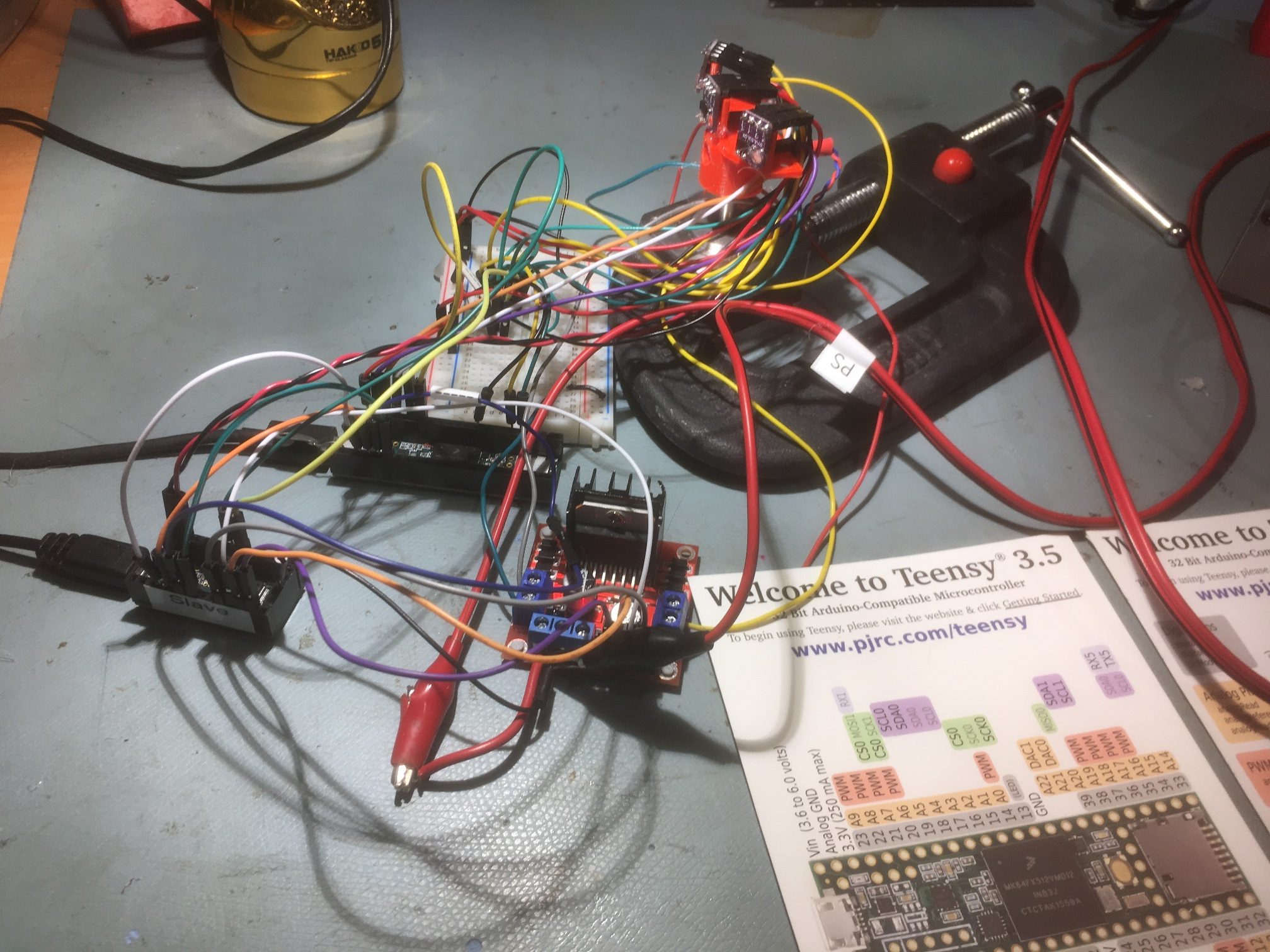
Rotary table Teensy 3.2 in foreground with L298N motor controller. Teensy 3.5 measurement controller in middle, with plugboard , NEMA 17 stepper motor and triple VL53L0X array in background
Here’s a short video showing a typical measurement scan:
And here’s a typical output:
|
1 2 3 4 5 6 7 8 9 10 11 12 |
Starting Angle Scan... Msec Step# RelDeg Front Center Rear Steer 94128 0 0.00 361 416 507 -0.35 94498 1 9.00 372 418 507 -0.32 94868 2 18.00 372 413 510 -0.33 95237 3 27.00 368 418 506 -0.33 95607 4 36.00 368 420 510 -0.34 95976 5 45.00 376 420 508 -0.31 96346 6 54.00 365 418 502 -0.33 SCAN_COMPLETE_PIN HIGH Received - Scan is Complete! Enter Q to quit, anything else for another scan |
In the above output, the ‘Step#’ and ‘RelDeg’ values were obtained from the rotary scanner program via the primary I2C bus, while the ‘Front’, ‘Center’, and ‘Rear’ distance values were obtained from the three VL53L0X ToF sensors via the secondary I2C bus. The ‘Steer’ value was calculated locally by the measurement controller.
Upgrade to Micro-step capable motor driver:
After getting everything to work properly, I was a bit puzzled why I wasn’t getting the correct relative angle values back from the rotary table subsystem. After a while I figured out that the reason was that the rotary table program calculates an integer number of steps based on the total angle change divided by the number of scan steps, and, in general, the result won’t be exact. When moving from one scan step to the next the motor moves an integer number of steps, which in general will not be the desired angle change. For a 60 degree scan arc with 6 steps, the desired angle/scan step is 10 deg, and at 1.8 deg/step this would result in 10/1.8 = 5.5555… motor steps/scan step. This value gets truncated to 5 motor steps/scan step, which results in each scan step being 1.8 deg/step * 5 steps = 9 deg/scan step. So, instead of the scan steps occurring at 0, 10, 20, 30, 40, 50, 60 deg, they are at 0, 9, 18, 27, 36, 45, and 54 deg, and the last 6 deg of scan is never covered.
The answer to this problem is to use a motor with more than 200 steps/rev, or to use a driver that can generate micro-steps, effectively increasing the angular resolution of the scan. After some Googling, and some rooting around in my parts box, I came up with the Pololu DRV8825 Stepper Motor Driver part. This driver supports up to 32 micro-steps/step and is considerably smaller than the L298N – such a deal!
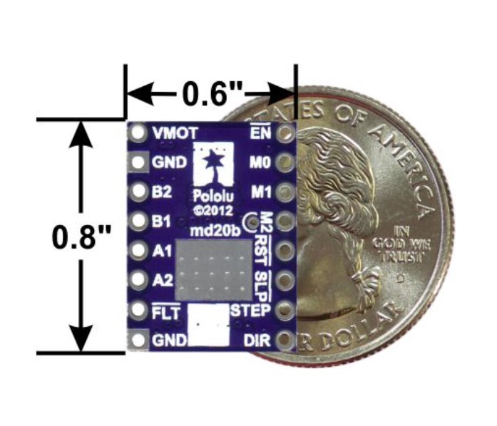
Pololu Micro-stepping Driver
At 32 microsteps/step, a full motor rev would take 200*32 = 6400 microsteps or 0.05625 deg/microstep . Now the above calculation would result in 10 deg/0.05625/10 = 177.777 –> 177 microsteps per scan step. This would result in step angles of 0, 177*0.05625 = 9.95802, 19.916, 29.874, 39.83, 49.79, and 59.748. So now we lose only the last 0.252 deg of scan – much nicer!
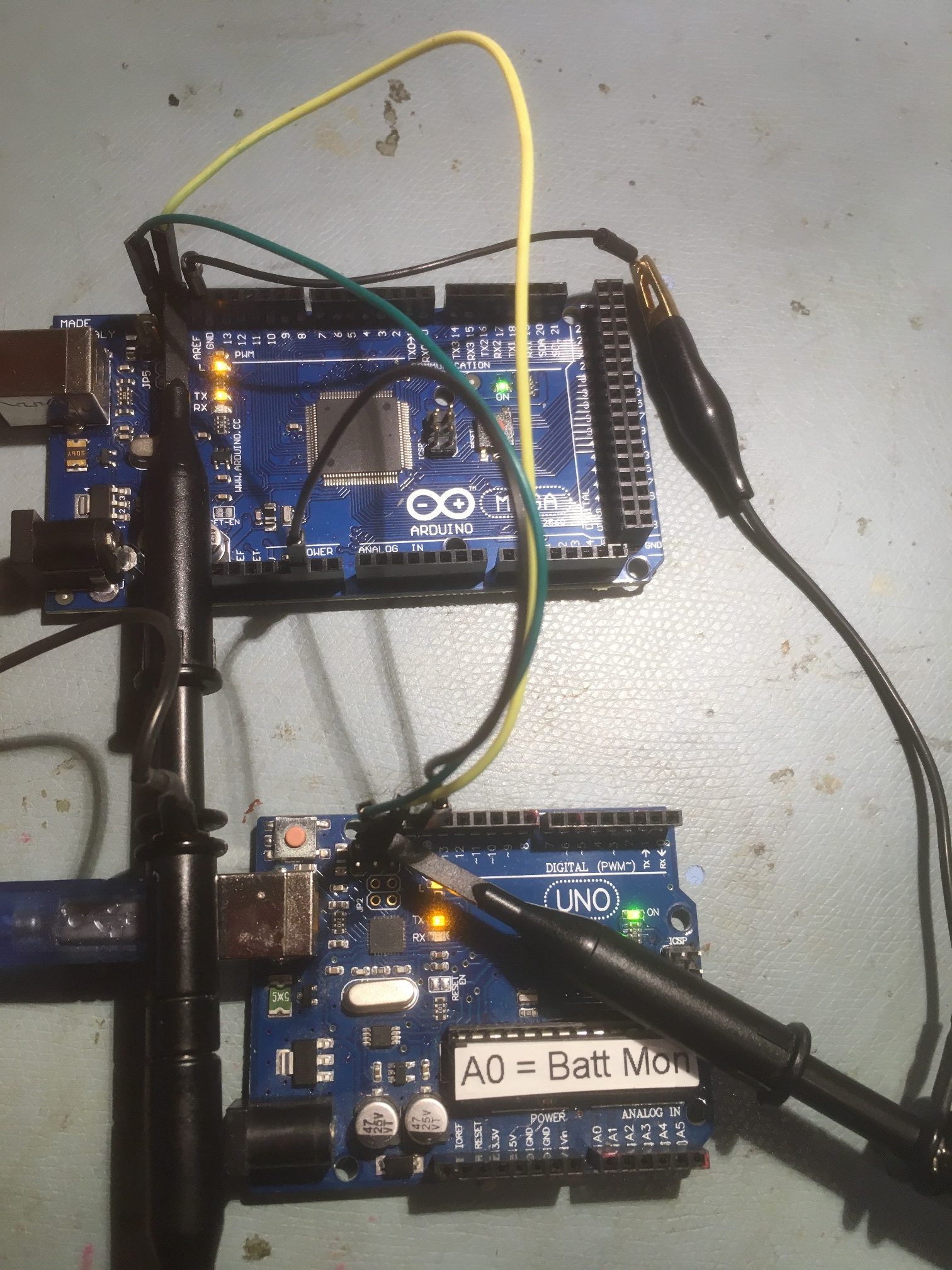
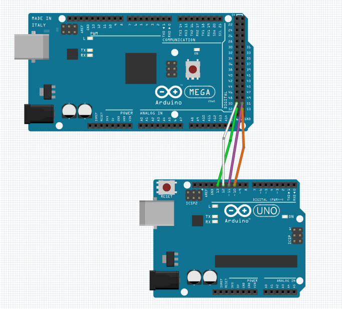
So, I put together a quick test, using an Arduino Uno, a spare NEMA 17 stepper motor, a Pololu DRV8825 from my parts box, and the Pololu Stepper library. Here’s the program:
|
1 2 3 4 5 6 7 8 9 10 11 12 13 14 15 16 17 18 19 20 21 22 23 24 25 26 27 28 29 30 31 32 33 34 35 36 37 38 39 40 41 42 43 44 45 46 47 48 49 50 51 52 53 54 55 56 57 58 59 60 61 62 63 64 65 66 67 68 69 70 71 72 73 74 75 76 77 78 79 80 81 82 83 84 85 86 87 88 89 90 91 92 93 94 95 96 97 98 99 100 101 102 103 104 105 106 107 108 |
/* Name: PololuMicroStepperDemoV2.ino Created: 5/31/2020 11:05:30 PM Author: FRANKNEWXPS15\Frank */ /* * Microstepping demo * * This requires that microstep control pins be connected in addition to STEP,DIR * * Copyright (C)2015 Laurentiu Badea * * This file may be redistributed under the terms of the MIT license. * A copy of this license has been included with this distribution in the file LICENSE. */ #include <Arduino.h> // Motor steps per revolution. Most steppers are 200 steps or 1.8 degrees/step #define MOTOR_STEPS 200 //#define RPM 120 #define RPM 12 #define DIR 8 #define STEP 9 #define SLEEP 13 // optional (just delete SLEEP from everywhere if not used) /* * Choose one of the sections below that match your board */ //#include "DRV8834.h" //#define M0 10 //#define M1 11 //DRV8834 stepper(MOTOR_STEPS, DIR, STEP, SLEEP, M0, M1); // #include "A4988.h" // #define MS1 10 // #define MS2 11 // #define MS3 12 // A4988 stepper(MOTOR_STEPS, DIR, STEP, SLEEP, MS1, MS2, MS3); #include "DRV8825.h" #define MODE0 10 #define MODE1 11 #define MODE2 12 DRV8825 stepper(MOTOR_STEPS, DIR, STEP, SLEEP, MODE0, MODE1, MODE2); // #include "DRV8880.h" // #define M0 10 // #define M1 11 // #define TRQ0 6 // #define TRQ1 7 // DRV8880 stepper(MOTOR_STEPS, DIR, STEP, SLEEP, M0, M1, TRQ0, TRQ1); // #include "BasicStepperDriver.h" // generic // BasicStepperDriver stepper(DIR, STEP); void setup() { /* * Set target motor RPM. */ stepper.begin(RPM); // if using enable/disable on ENABLE pin (active LOW) instead of SLEEP uncomment next line // stepper.setEnableActiveState(LOW); stepper.enable(); // set current level (for DRV8880 only). // Valid percent values are 25, 50, 75 or 100. // stepper.setCurrent(100); } void loop() { delay(1000); /* * Moving motor in full step mode is simple: */ stepper.setMicrostep(1); // Set microstep mode to 1:1 // One complete revolution is 360° stepper.rotate(360); // forward revolution stepper.rotate(-360); // reverse revolution // One complete revolution is also MOTOR_STEPS steps in full step mode stepper.move(MOTOR_STEPS); // forward revolution stepper.move(-MOTOR_STEPS); // reverse revolution /* * Microstepping mode: 1, 2, 4, 8, 16 or 32 (where supported by driver) * Mode 1 is full speed. * Mode 32 is 32 microsteps per step. * The motor should rotate just as fast (at the set RPM), * but movement precision is increased, which may become visually apparent at lower RPMs. */ stepper.setMicrostep(8); // Set microstep mode to 1:8 // In 1:8 microstepping mode, one revolution takes 8 times as many microsteps stepper.move(8 * MOTOR_STEPS); // forward revolution stepper.move(-8 * MOTOR_STEPS); // reverse revolution // One complete revolution is still 360° regardless of microstepping mode // rotate() is easier to use than move() when no need to land on precise microstep position stepper.rotate(360); stepper.rotate(-360); delay(5000); } |
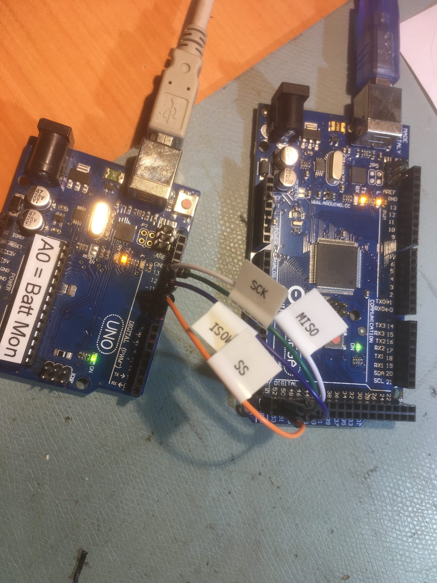
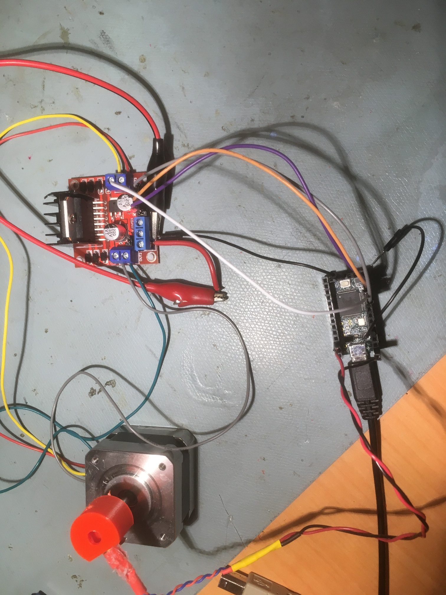
And the hardware test setup:
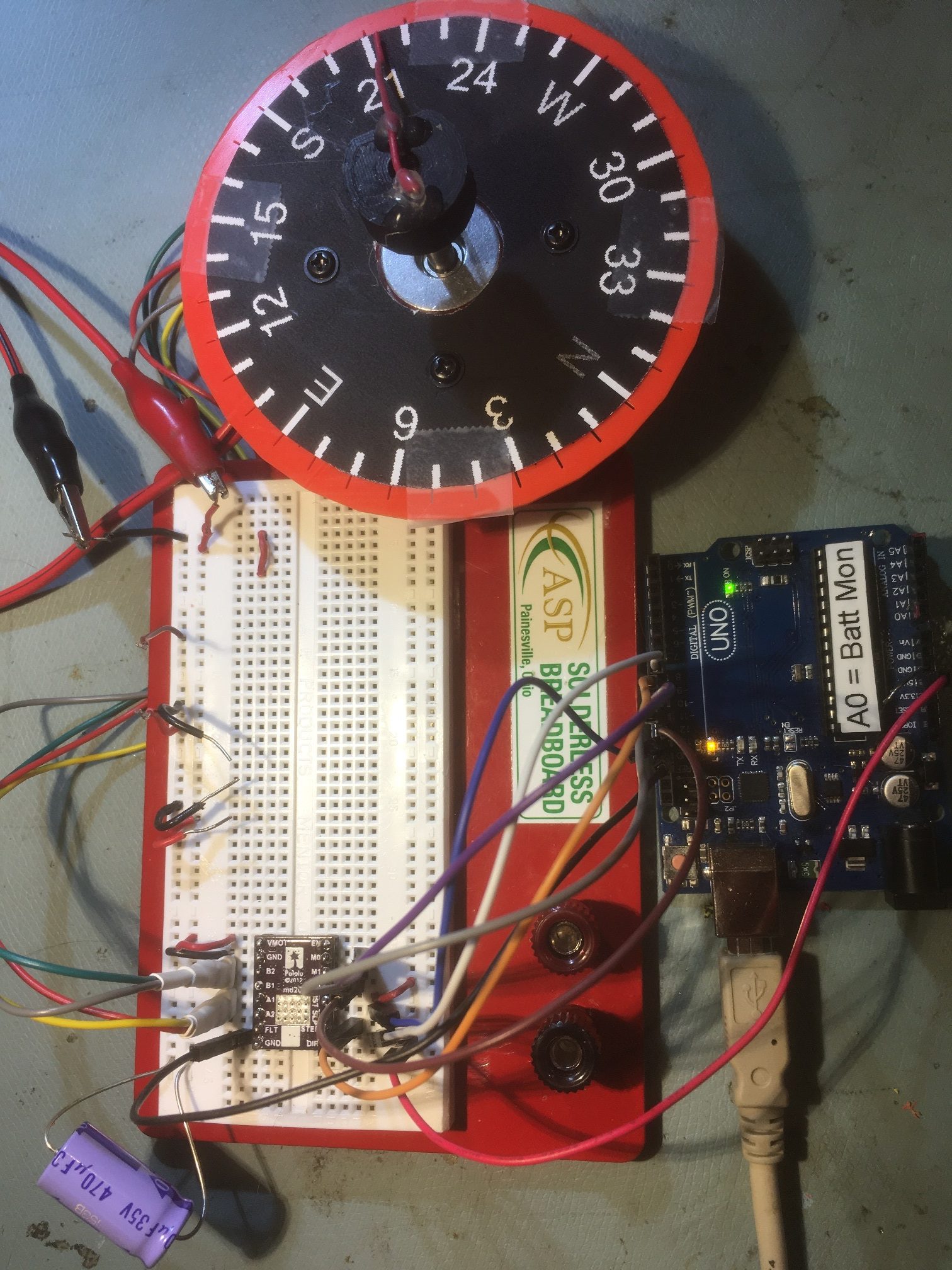
Pololu DRV8825 Microstep demo setup.
And a short video showing the stepper motor action. Note that close attention to the end of the red pointer wire shows the difference between ‘full-step’ and ‘micro-stepped’ behavior; the micro-stepped rotations are much smoother. Also, if you look very carefully, you can see the compass rose platform ‘counter-rotating’ in full-step mode, as the torque is high enough to rotate the stepper motor in the opposite direction to the shaft.
So now the idea is to incorporate micro-stepping capability into the Teensy NEMA 17 Rotary Table program, so that angle scans can be performed much more accurately than before.
02 June 2020 Update:
My original Pololu Microstep Demo program used an Arduino Uno to control the Pololu DRV8825 motor driver, but my Teensy Rotary Table setup obviously uses a Teensy and an L298N. To change the Rotary Table setup to utilize the DRV8825, I’ll need to make some adjustments to pin configurations.
The first step in the process was to change out the Arduino Uno for a Teensy (a Teensy 3.5 in this case) to verify that there were no problem with the Pololu microstep demo program running on a Teensy – done.
The next step was to change out the L298N driver on the rotary table setup with the Pololu DRV8825 driver, and modify the rotary table program to use the new driver with microstepping.
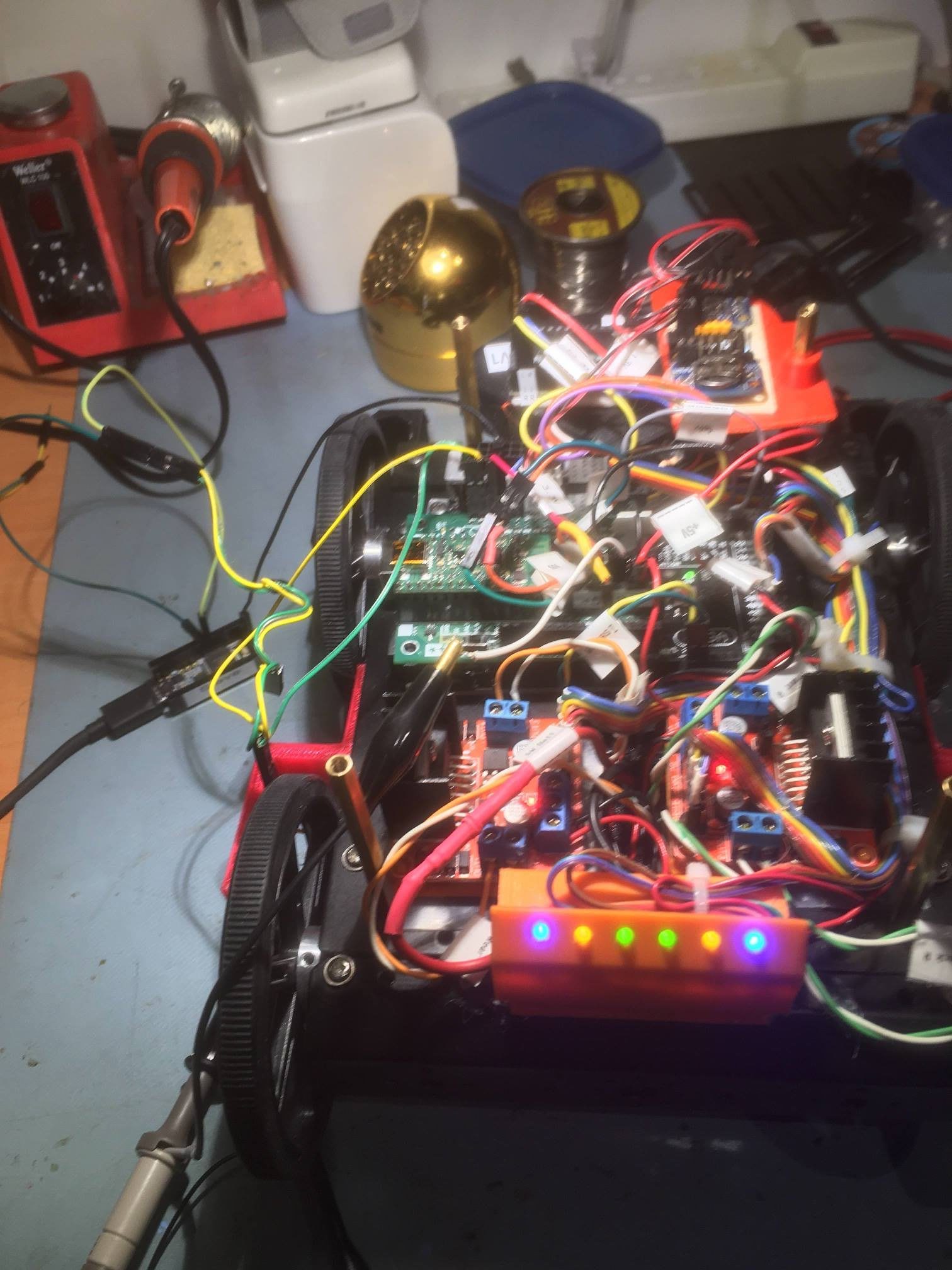
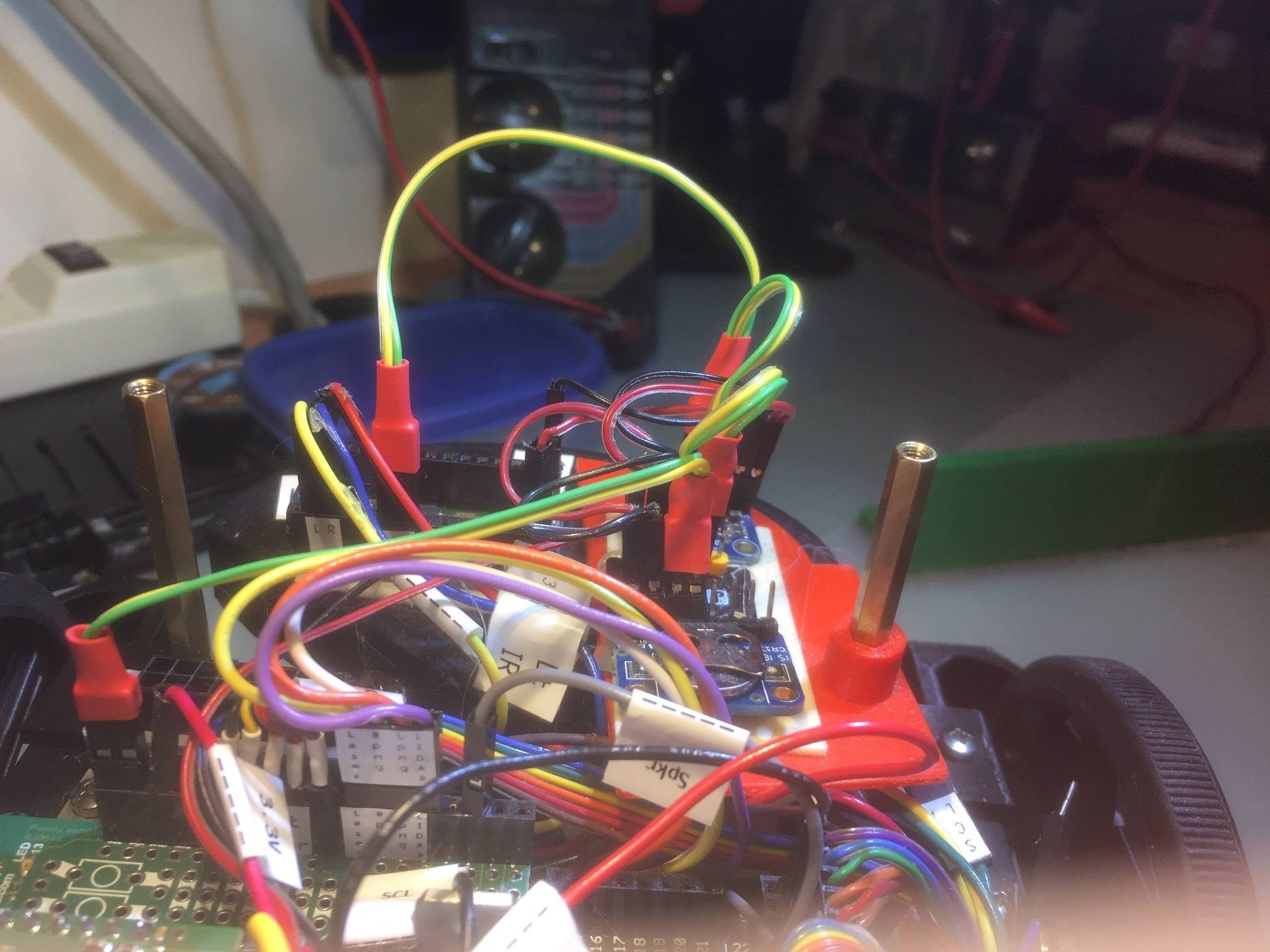
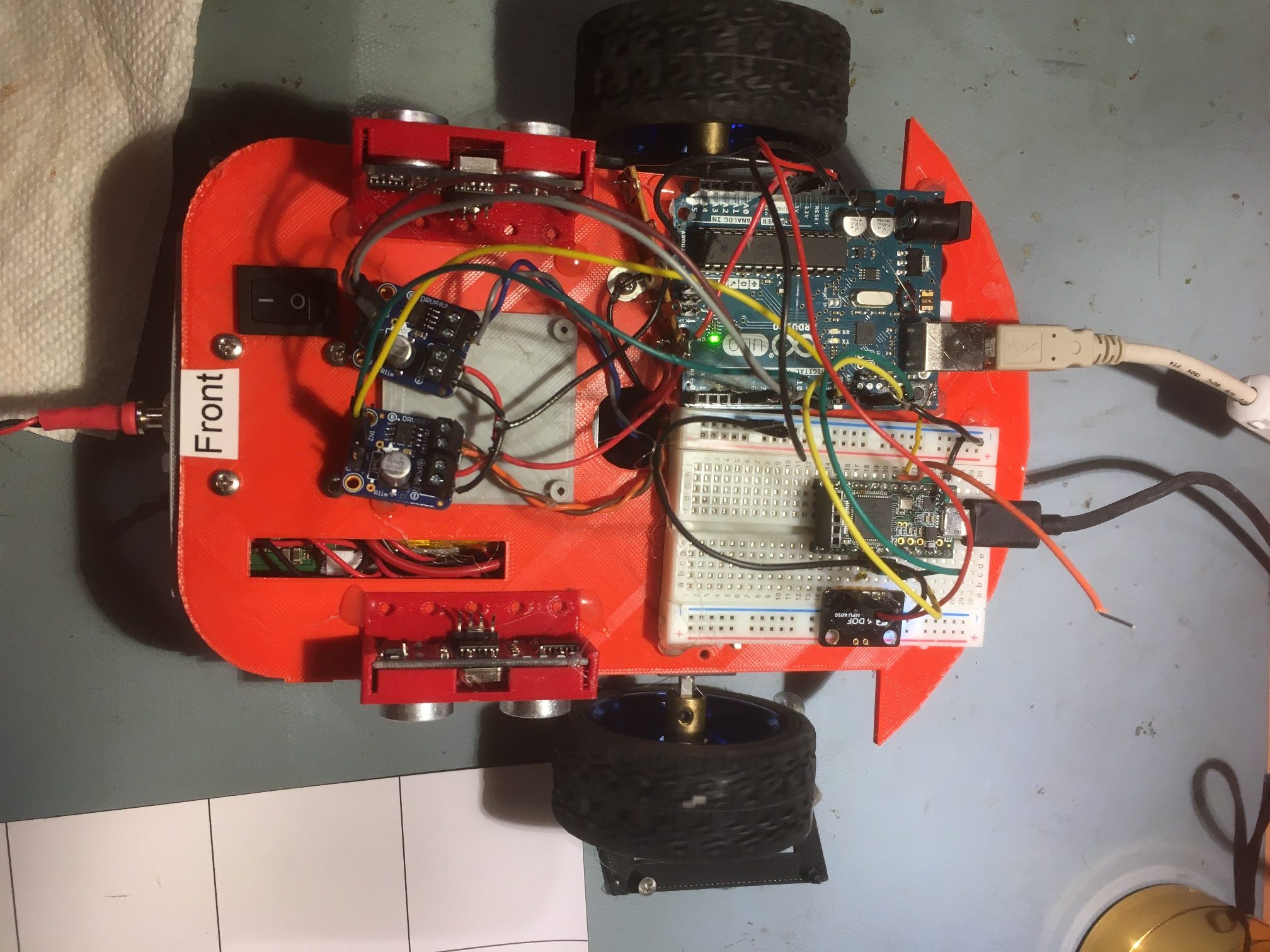
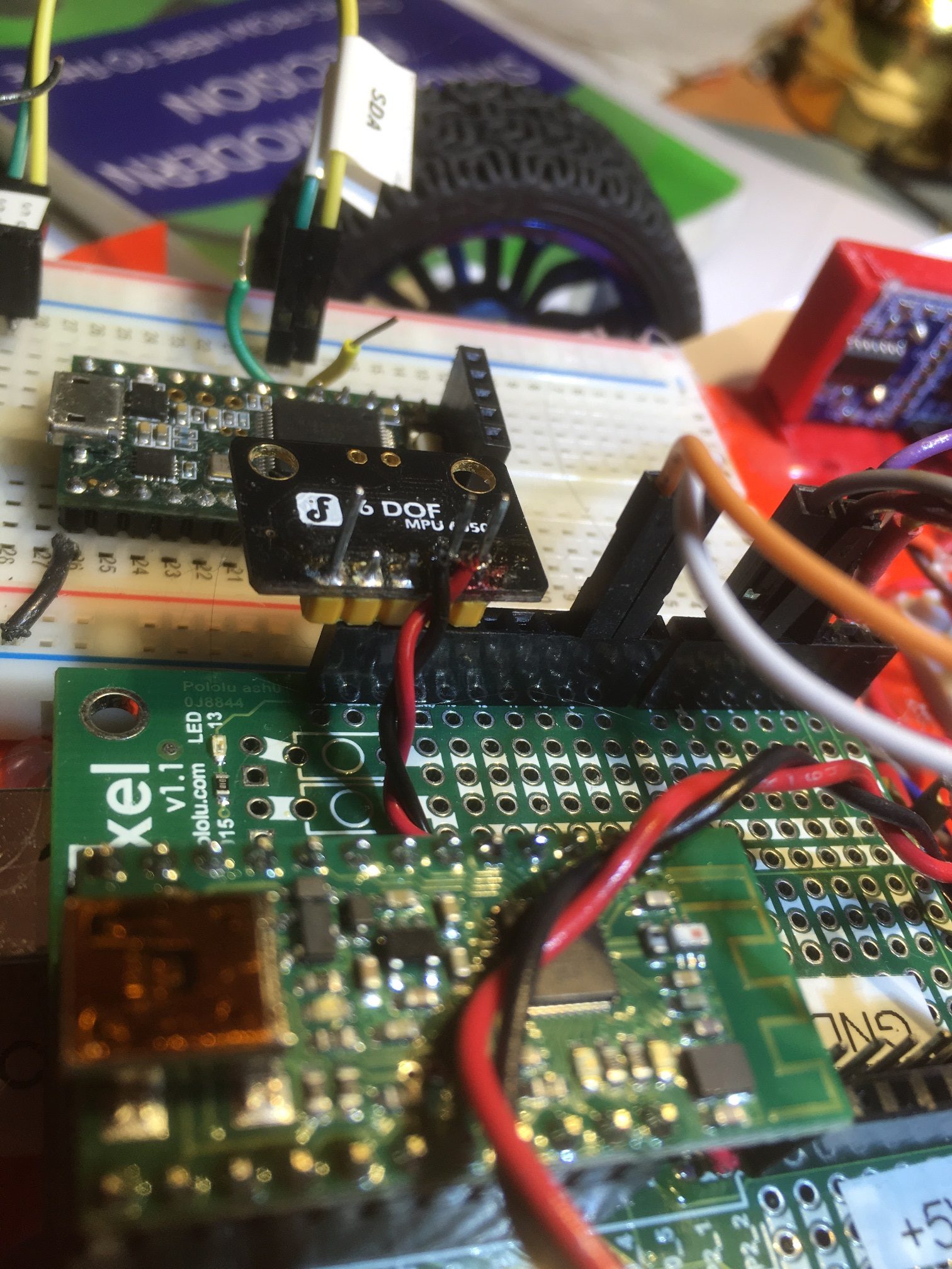
Here’s the new combined hardware layout, with both the rotary table and measurement sub-systems shown
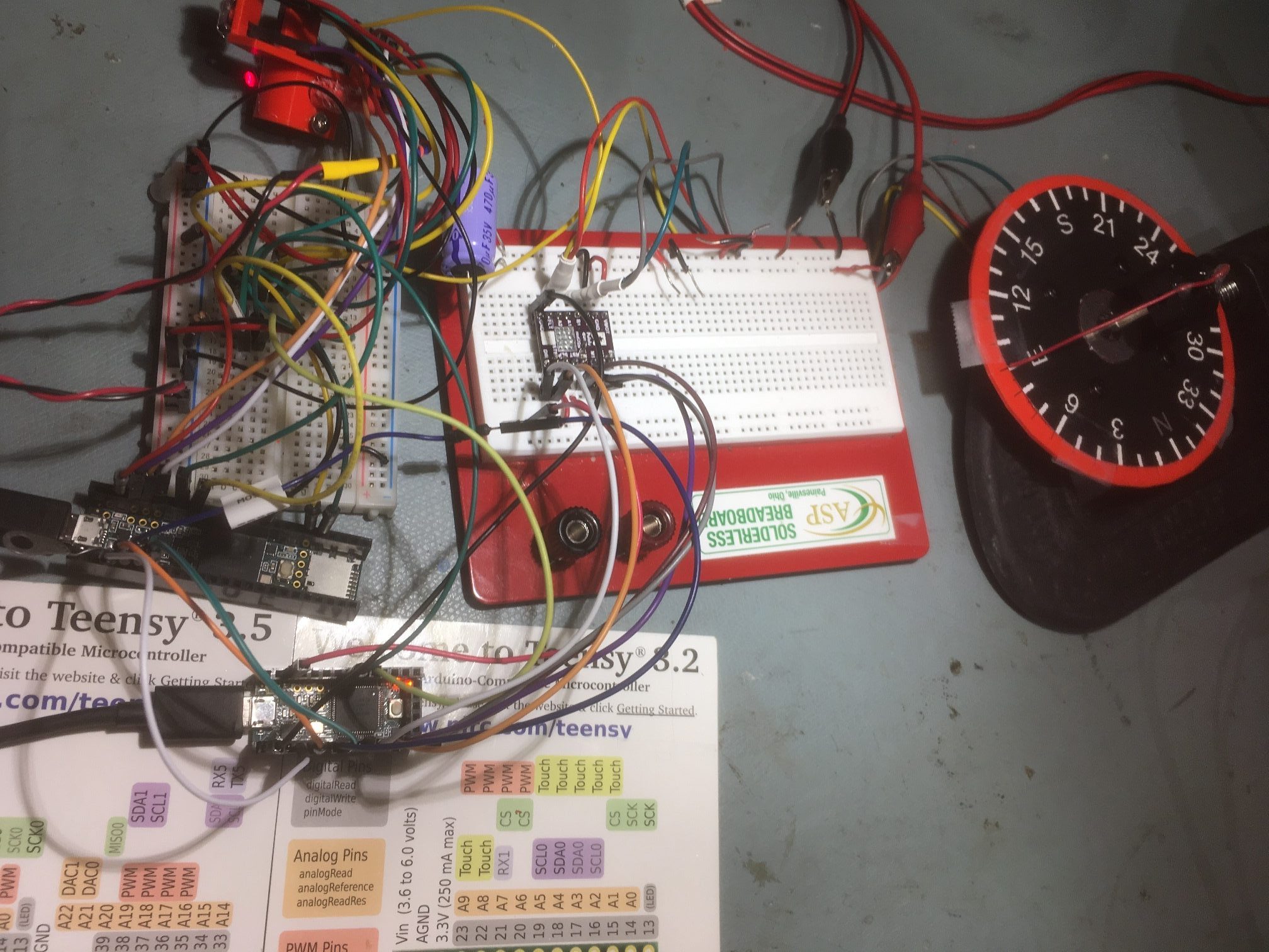
Both measurement and rotary table sub-systems shown. Rotary table Teensy 3.2 at left foreground, followed by Teensy 3.5 measurement controller, the connection plugboard, and the triple VL53L0X sensors in the left background. The new DRV8825 is mounted on the center plugboard, and the NEMA 17 stepper motor with compass rose test platter at the right
Here’s the updated software using the Pololu DRV8825
|
1 2 3 4 5 6 7 8 9 10 11 12 13 14 15 16 17 18 19 20 21 22 23 24 25 26 27 28 29 30 31 32 33 34 35 36 37 38 39 40 41 42 43 44 45 46 47 48 49 50 51 52 53 54 55 56 57 58 59 60 61 62 63 64 65 66 67 68 69 70 71 72 73 74 75 76 77 78 79 80 81 82 83 84 85 86 87 88 89 90 91 92 93 94 95 96 97 98 99 100 101 102 103 104 105 106 107 108 109 110 111 112 113 114 115 116 117 118 119 120 121 122 123 124 125 126 127 128 129 130 131 132 133 134 135 136 137 138 139 140 141 142 143 144 145 146 147 148 149 150 151 152 153 154 155 156 157 158 159 160 161 162 163 164 165 166 167 168 169 170 171 172 173 174 175 176 177 178 179 180 181 182 183 184 185 186 187 188 189 190 191 192 193 194 195 196 197 198 199 200 201 202 203 204 205 206 207 208 209 210 211 212 213 214 215 216 217 218 219 220 221 222 223 224 225 226 227 228 229 230 231 232 233 234 235 236 237 238 239 240 241 242 243 244 245 246 247 248 249 250 251 252 253 254 255 256 257 258 259 260 261 262 263 264 265 266 267 268 269 270 271 272 273 274 275 276 277 278 279 280 281 282 283 284 285 286 287 288 289 290 291 292 293 294 295 296 297 298 299 300 301 302 303 304 305 306 307 308 309 310 311 312 313 314 315 316 317 318 319 320 321 322 323 324 325 326 327 328 329 330 331 332 333 334 335 336 337 338 339 340 341 342 343 344 345 346 |
/* Name: Teensy_DRV8825_Rotary_Scan_Table.ino Created: 6/4/2020 12:59:57 AM Author: FRANKNEWXPS15\Frank */ /* Teensy DRV8825 Rotary Table Program This program controls a NEMA 17 stepper motor using a Pololu DRV8825 motor driver. It Takes user input to define the boresight (zero) position and the start and stop angles in degrees relative to the zero position. Then it moves to the start position and waits for a HIGH level on SCAN_START_PIN. After this signal is received, the motor is stepped through to the stop position. At the stop position, the SCAN_COMPLETE_PIN is driven HIGH. The Stepper motor is connected to a DRV8825 motor driver with one coil on A1/A2, and the other coil on B1/B2. It may turn out that one coil's leads have to be reversed to match the motor rotation direction with the program direction. The NEMA 17 motor is assumed to execute 200 steps/revolution. Change the StepsPerRevolution constant for other values. 05/27/20: Performs an angular scan over user-supplied range of angles. By default a complete scan from start position to stop position is performed, followed by a return to the start position However, if the STEP_ENABLE_PIN (held HIGH by default) is pulled LOW, the program will wait until it goes HIGH before performing the next step. In this case, a scan iteration would go as follows Step 1 - Scan parameters entered, motor moves to start position, waits for LOW on SCAN_START_PIN Step 2 - Measurement program pulls SCAN_START_PIN LOW for 1 sec, then back HIGH Step 3 - Measurement program takes a measurement & retrieves step# & angle value via I2C request Step 4 - Measurement program pulls SCAN_STEP_ENABLE_PIN LOW Step 5 - Motor moves to first/next step, and outputs HIGH on SCAN_STEP_COMPLETE_PIN Step 6 - Measurement program waits for HIGH on SCAN_STEP_COMPLETE_PIN Step 7 - Measurement program takes a measurement & retrieves step# & angle value via I2C request Step 8 - Repeat Steps 4-7 until scan complete Step 9 - SCAN_COMPLETE_PIN goes HIGH */ //O5/30/20 Added I2C connection to pass step# & relative angle values to measurement program //05/02/20 Rev to use Pololu DRV8825 & micro-stepping #include <Wire.h> #include "I2C_Anything.h" #include "DRV8825.h" const int SLAVE_ADDR = 8; //added 05/30/20 #pragma region MOTOR_CONSTANTS // Motor steps per revolution. Most steppers are 200 steps or 1.8 degrees/step //06/02/20 now using Pololu DRV8825 const int MOTOR_STEPS_PER_REV = 200; const int MICROSTEPS_PER_STEP = 32; const int MICROSTEPS_PER_REV = MICROSTEPS_PER_STEP * MOTOR_STEPS_PER_REV; const int DEG_PER_MICROSTEP = 360 / MICROSTEPS_PER_REV; const int MICROSTEPS_PER_DEG = MICROSTEPS_PER_REV / 360; const int DEFAULT_RPM = 12; const int POSITIONING_SPEED_RPM = 100; const int DEFAULT_MOTOR_STEPS_TO_MOVE = 10; #pragma endregion Motor Constants #pragma region PIN_ASSIGNMENTS const int DIR = 8; const int STEP = 9; const int SLEEP = 13; // optional (just delete SLEEP from everywhere if not used) const int MODE0 = 10; const int MODE1 = 11; const int MODE2 = 12; const int SCAN_START_PIN = 2; const int SCAN_STEP_ENABLE_PIN = 3; const int SCAN_STEP_COMPLETE_PIN = 4; const int SCAN_COMPLETE_PIN = 5; #pragma endregion Pin Assignments DRV8825 stepper(MOTOR_STEPS_PER_REV, DIR, STEP, SLEEP, MODE0, MODE1, MODE2); char Instr[20]; //DRV8825 int zeroPos; int scanStartDeg; int scanStartMicroSteps; //scanStartDeg converted to steps int scanStopDeg; int scanStopSteps; //scanStopDeg converted to steps int scanNumberofSteps; //added 05/27/20 int stepsToMove; //steps to move to initial position int curMotorStepVal; //keeps track of current position, in steps float curRelPointingAngleDeg; //keeps track of current relative pointing angle, in degrees int curAngleStepVal; //keeps track of current table step iteration value bool bStopPosDone = false; int scanSpeedRpm = 6; void setup() { //added 05/30/20 to provide step# & angle values to Angle Scan program Wire.begin(SLAVE_ADDR); Wire.setSCL(18); Wire.setSCL(19); Wire.setClock(100000); Wire.onRequest(requestEvent); //06/02/20 now using Pololu DRV8825 microstepping motor driver stepper.begin(DEFAULT_RPM); // if using enable/disable on ENABLE pin (active LOW) instead of SLEEP uncomment next line // stepper.setEnableActiveState(LOW); stepper.enable(); /* * Microstepping mode: 1, 2, 4, 8, 16 or 32 (where supported by driver) * Mode 1 is full speed. * Mode 32 is 32 microsteps per step. * The motor should rotate just as fast (at the set RPM), * but movement precision is increased, which may become visually apparent at lower RPMs. */ stepper.setMicrostep(MICROSTEPS_PER_STEP); // Set microstep mode to 1:32 Serial.begin(115200); unsigned long now = millis(); while (!Serial) { delay(10); } delay(5000); //05/28/20 delay AFTER Serial object instantiation is NECESSARY! Serial.print("Serial available after "); Serial.print(millis() - now); Serial.print(" millisec"); pinMode(SCAN_START_PIN, INPUT_PULLUP); pinMode(SCAN_STEP_ENABLE_PIN, INPUT_PULLUP); pinMode(SCAN_STEP_COMPLETE_PIN, OUTPUT); pinMode(SCAN_COMPLETE_PIN, OUTPUT); //init SCAN_COMPLETE_PIN, SCAN_STEP_COMPLETE to LOW (not complete) state digitalWrite(SCAN_COMPLETE_PIN, LOW); digitalWrite(SCAN_STEP_COMPLETE_PIN, LOW); //added 05/26/20 Serial.printf("Serial.printf: NEMA-17 Stepper Rotary Table Program\n"); //get motor speed to be used scanSpeedRpm = GetIntegerParameter("Motor speed RPM", 6); //set zero position Serial.println("Set stepper zero position. Enter +steps for CW, -steps for CCW, Q to exit"); while (!bStopPosDone) { while (Serial.available() == 0); //waits for input if (toascii(Serial.peek()) == 'Q' || toascii(Serial.peek()) == 'q') { bStopPosDone = true; curMotorStepVal = 0; } else { stepsToMove = GetIntegerParameter("Steps to move (- = CCW, + = CW)?", DEFAULT_MOTOR_STEPS_TO_MOVE); Serial.print("Steps to move = "); Serial.println(stepsToMove); stepper.setRPM(POSITIONING_SPEED_RPM); stepper.move(stepsToMove); } } Serial.readString(); //clear the input buffer - could still have chars in it Serial.print("curMotorStepVal = "); Serial.println(curMotorStepVal); //set scan start/stop positions in degrees scanStartDeg = GetIntegerParameter("Scan Start Pos in Degrees Relative to Zero", -90); scanStopDeg = GetIntegerParameter("Scan Stop Pos in Degrees Relative to Zero", 90); scanNumberofSteps = GetIntegerParameter("Number of Steps", 18); curRelPointingAngleDeg = scanStartDeg; //added 05/30/20 Serial.println("Run Parameters:"); Serial.print("Speed: "); Serial.print(scanSpeedRpm); Serial.println(" RPM"); Serial.print("Scan Start: "); Serial.print(scanStartDeg); Serial.println(" Deg"); Serial.print("Scan Stop: "); Serial.print(scanStopDeg); Serial.println(" Deg"); Serial.print("Scan Steps: "); Serial.println(scanNumberofSteps); //06/02/20 Now using Pololu DRV8825 driver & microstepping int scandeg = abs(scanStopDeg - scanStartDeg); double scanstepdeg = scandeg / scanNumberofSteps; //go to scan start pos stepper.setRPM(POSITIONING_SPEED_RPM); stepper.rotate(scanStartDeg); while (1) //user has opportunity to exit after each scan { //wait for trigger Serial.printf("waiting for LOW on SCAN_START_PIN (pin %d) ...\n", SCAN_START_PIN); while (digitalRead(SCAN_START_PIN) == HIGH) { delay(100); } Serial.println("Scan Triggered - starting scan, setting SCAN_COMPLETE_PIN to LOW\n"); digitalWrite(SCAN_COMPLETE_PIN, LOW); stepper.setRPM(scanSpeedRpm); for (curAngleStepVal = 1; curAngleStepVal <= scanNumberofSteps; curAngleStepVal++) { curRelPointingAngleDeg = scanStartDeg + (curAngleStepVal)*scanstepdeg; //when SCAN_STEP_ENABLE_PIN goes LOW, go to first/next step. while (digitalRead(SCAN_STEP_ENABLE_PIN)) { } unsigned long now = millis(); digitalWrite(SCAN_STEP_COMPLETE_PIN, LOW); Serial.printf("Scan Step %d Triggered: moving to %3.2f deg\n", curAngleStepVal, curRelPointingAngleDeg); //DRV8825 stepper.rotate(scanstepdeg); //rotate to next scan angle //output HIGH on SCAN_STEP_COMPLETE_PIN //DEBUG!! //Serial.printf("Outputting HIGH on SCAN_STEP_COMPLETE_PIN\n"); //Serial.printf("Done in %lu Msec - Current Angle = %3.2f\n", millis() - now, curRelPointingAngleDeg); //DEBUG!! digitalWrite(SCAN_STEP_COMPLETE_PIN, HIGH); //delay(50); //make the HIGH period visible on scope } //quit Serial.printf("Outputting HIGH on SCAN_COMPLETE_PIN (pin %d)\n", SCAN_COMPLETE_PIN); digitalWrite(SCAN_COMPLETE_PIN, HIGH); //return to start position //DRV8825 stepper.setRPM(POSITIONING_SPEED_RPM); stepper.rotate(-scandeg); //re-initialize step counter and current pointing angle curAngleStepVal = 0; curRelPointingAngleDeg = scanStartDeg; Serial.printf("Enter any key to continue\n"); while (!Serial.available()) { } //consume bytes until Serial buffer is empty to avoid unintended triggers int incomingByte; while (Serial.available()) { incomingByte = Serial.read(); Serial.printf("Consuming 0x%x\n", incomingByte); } } } void loop() { } int GetIntegerParameter(String prompt, int defaultval) { int param = 0; bool bDone = false; while (!bDone) { Serial.print(prompt); Serial.print(" ("); Serial.print(defaultval); Serial.print("): "); while (Serial.available() == 0); //waits for input //String res = Serial.readString().trim(); String res = Serial.readString(); res.trim(); int reslen = res.length(); if (reslen == 0) //user entered CR only { bDone = true; param = defaultval; } else { res.toCharArray(Instr, reslen + 1); //if (isNumeric(Instr) && atoi(Instr) >= 0) if (isNumeric(Instr)) { param = atoi(Instr); bDone = true; } else { Serial.print(Instr); Serial.println(" Is invalid input - please try again"); } } } Serial.println(param); return param; } // check a string to see if it is numeric and accept Decimal point //copied from defragster's post at https://forum.pjrc.com/threads/27842-testing-if-a-string-is-numeric bool isNumeric(char* str) { byte ii = 0; bool RetVal = false; if ('-' == str[ii]) ii++; while (str[ii]) { if ('.' == str[ii]) { ii++; break; } if (!isdigit(str[ii])) return false; ii++; RetVal = true; } while (str[ii]) { if (!isdigit(str[ii])) return false; ii++; RetVal = true; } return RetVal; } //05/30/20 added to report current angle step# & relative pointing angle to measurement program void requestEvent() { //send the current step# and current relative pointing angle //DEBUG!! //Serial.printf("In requestEvent: curAngleStep = %d, curRelAngle = %2.2f\n", // curAngleStepVal, curAngleStepVal, curRelPointingAngleDeg, curRelPointingAngleDeg); //DEBUG!! I2C_writeAnything(curAngleStepVal); I2C_writeAnything(curRelPointingAngleDeg); } |
And the updated hardware schematic:
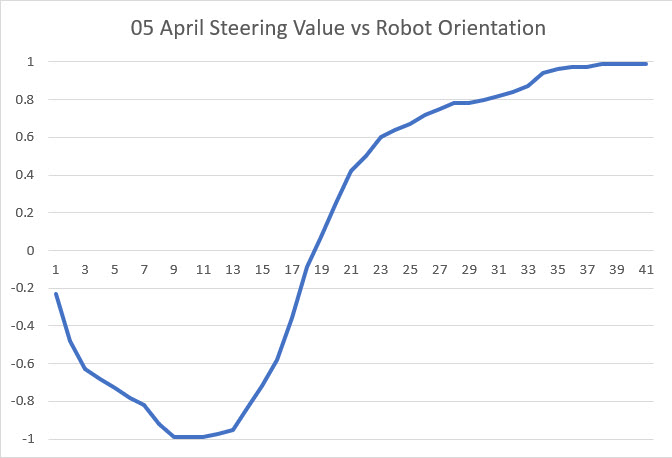
Here’s the output from a typical 180-degree scan
The triple VL53L0X scanner program:
|
1 2 3 4 5 6 7 8 9 10 11 12 13 14 15 16 17 18 19 20 21 22 23 24 |
Starting Angle Scan... Msec Step# RelDeg Front Center Rear Steer 23815846 0 -90.00 121 30 17 3.47 23816965 1 -80.00 120 28 19 3.61 23817408 2 -70.00 118 29 18 3.45 23817852 3 -60.00 120 30 20 3.33 23818296 4 -50.00 123 32 19 3.25 23818740 5 -40.00 120 28 20 3.57 23819183 6 -30.00 122 30 19 3.43 23819627 7 -20.00 119 29 22 3.34 23820071 8 -10.00 122 29 19 3.55 23820515 9 0.00 121 31 20 3.26 23820958 10 10.00 122 31 17 3.39 23821402 11 20.00 120 30 16 3.47 23821846 12 30.00 120 27 22 3.63 23822290 13 40.00 120 31 20 3.23 23822733 14 50.00 124 29 19 3.62 23823177 15 60.00 120 30 19 3.37 23823621 16 70.00 123 29 23 3.45 23824065 17 80.00 120 31 18 3.29 23824508 18 90.00 116 31 20 3.10 SCAN_COMPLETE_PIN HIGH Received - Scan is Complete! Enter Q to quit, anything else for another scan |
The DRV8825 Rotary Table program:
|
1 2 3 4 5 6 7 8 9 10 11 12 13 14 15 16 17 18 19 20 21 22 23 |
waiting for LOW on SCAN_START_PIN (pin 2) ... Scan Triggered - starting scan, setting SCAN_COMPLETE_PIN to LOW Scan Step 1 Triggered: moving to -80.00 deg Scan Step 2 Triggered: moving to -70.00 deg Scan Step 3 Triggered: moving to -60.00 deg Scan Step 4 Triggered: moving to -50.00 deg Scan Step 5 Triggered: moving to -40.00 deg Scan Step 6 Triggered: moving to -30.00 deg Scan Step 7 Triggered: moving to -20.00 deg Scan Step 8 Triggered: moving to -10.00 deg Scan Step 9 Triggered: moving to 0.00 deg Scan Step 10 Triggered: moving to 10.00 deg Scan Step 11 Triggered: moving to 20.00 deg Scan Step 12 Triggered: moving to 30.00 deg Scan Step 13 Triggered: moving to 40.00 deg Scan Step 14 Triggered: moving to 50.00 deg Scan Step 15 Triggered: moving to 60.00 deg Scan Step 16 Triggered: moving to 70.00 deg Scan Step 17 Triggered: moving to 80.00 deg Scan Step 18 Triggered: moving to 90.00 deg Outputting HIGH on SCAN_COMPLETE_PIN (pin 5) Enter any key to continue |
For anyone interested in using this program, it is available on my GitHub site at https://github.com/paynterf/Teensy-DRV8825-Rotary-Scan-Table