Posted 14 August 2023
In previous versions of the WallE3 operating system I used three functions to deal with anomalous conditions. At each update interval (currently set to 50mSec) I called a function called UpdateAllEnvironmentalParameters() which updated all sensor measurements; then a second function called CheckForAnomalousConditions() to update anomaly condition flags (like ‘gl_DeadBattery’, ‘gl_bStuckAhead’ and the like), and a third function, called HandleAnomalousConditions() to actually respond properly to any anomalous condition identified in CheckForAnomalousConditions().
However, I wasn’t really happy with the program flow with this arrangement, so in the current version (WallE3_Complete_V4) I eliminated CheckForAnomalousConditions() entirely and pulled the anomaly flag update code into UpdateAllEnvironmentalParameters(). I also replaced HandleAnomalousConditions() with a ‘switch(gl_LastAnomalyCode)’ block at the top of the loop() function, just before the code that decides which wall (left or right) is to be tracked. So now the program flow looks like this:
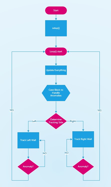
So, very simple and very direct. The ‘case’ block looks like this (only the ‘ExcessSteerVal’ case has been populated at the moment):
|
1 2 3 4 5 6 7 8 9 10 11 12 13 14 15 16 17 18 19 20 21 22 23 24 25 26 27 28 29 30 31 32 |
switch (gl_LastAnomalyCode) { case ANOMALY_NONE: break; case ANOMALY_STUCK_AHEAD: break; case ANOMALY_STUCK_BEHIND: break; case ANOMALY_OBSTACLE_AHEAD: break; case ANOMALY_WALL_OFFSET_DIST_AHEAD: break; case ANOMALY_OBSTACLE_BEHIND: break; //ANOMALY_OPEN_CORNER case removed - it is now handled as part of ANOMALY_EXCESS_STEER_VAL case //case ANOMALY_OPEN_CORNER: // break; case ANOMALY_DEAD_BATTERY: break; case ANOMALY_CHARGER_CONNECTED: break; case ANOMALY_OPEN_DOORWAY: break; case ANOMALY_TRACKING_WRONG_WALL: break; case ANOMALY_EXCESS_STEER_VAL: HandleExcessSteervalCase(); break; default: break; } |
I think this is going to be a robust flow; Any anomaly causes the current tracking operation to break and return control to the top of loop(). Then the case statement handles the anomaly as required, and drops the program right back into left/right wall tracking determination. If no anomalies are encountered (unlikely, but could happen) then the tracking block runs forever.
15 August 2023 Update:
I’m working on populating the ‘ANOMALY_STUCK_AHEAD’ case in the ‘switch (gl_LastAnomalyCode)’ block. The function ExecuteStuckRecoveryManeuver(WallTrackingCases trkdir) already exists, but it requires a ‘WallTrackingCases trkdir’ parameter to specify which wall is currently being tracked. I have a global ‘TrackingCases’ variable called ‘gl_CurTrackingCase’, but it isn’t clear to me how it is initiated and updated in the code.
Searching for ‘gl_CurTrackingCase’ produces the following hits:
- it is initialized to ‘WallTrackingCases::TRACKING_NEITHER’ in the pre-setup initialization block
- It is set to ‘TRACKING_LEFT’ at the top of TrackLeftWallOffset()
- It is set to ‘TRACKING_RIGHT’ at the top of TrackRightWallOffset()
- In ‘HandleExcessSteervalCase()’ it is updated to either TRACKING_LEFT or TRACKING_RIGHT, depending on current left/right distances, and then used as the input to several ‘RotateToParallelOrientation()’ and ‘SpinTurn()’ calls.
Looking at the above list, it appears that the value stored in gl_CurTrackingCase by the TrackLeftWallOffset() & TrackRightWallOffset() functions is never used; in HandleExcessSteervalCase() (the only function that references gl_CurTrackingCase), the value of the variable is updated locally by checking current left/right wall distances. IOW, the initialization lines in TrackLeftWallOffset() & TrackRightWallOffset() could be removed and the references to gl_CurTrackingCase in HandleExcessSteervalCase() could be converted to local variables and nothing would change.
So it appears that there are two ways to skin this cat.
- Keep gl_CurTrackingCase as a global variable that is updated in TrackLeftWallOffset() & TrackRightWallOffset() to reflect the current tracking case, and then reference it in HandleExcessSteervalCase() without regenerating the value from left/right wall distances. Keep the current definition of ExecuteStuckRecoveryManeuver(WallTrackingCases trkdir) and call it from the ‘ANOMALY_STUCK_AHEAD’ case block, with ‘trkdir’ replaced by gl_CurTrackingCase.
- Remove the ‘gl_CurTrackingCase’ global variable entirely, and use current left/right distances to determine the tracking case anywhere it is needed.
Of these two options, I prefer the first one. At the point where either TrackLeftWallOffset() & TrackRightWallOffset() are called, the tracking case is known current left/right distance comparisons, and inside either tracking function, the tracking case doesn’t change. When the active tracking function exits to the top of loop() due to an anomaly (the only way it can exit), the extant tracking case is still what it was at function exit. The only way it should change is from another left/right distance comparison after the current anomaly has been resolved.
16 August 2023 Update:
Oops! I ‘simplified’ HandleExcessSteervalCase() and now it doesn’t work anymore – ugh! The problem is I didn’t have a good understanding of how this function decides which wall to track. Its usually (but not necessarily) the other wall from the one identified in gl_CurTrackingCase, so I actually have to check left/right distances as was done in the ‘unsimplified’ version. So most of the time, HandleExcessSteervalCase() will change gl_CurTrackingCase to the ‘other’ wall
19 August 2023 Update:
Well, things are a bit more complicated than I thought. While chasing other bugs, I realized that there are other places in the code that use anomaly detection – oops. Now I have a CASE block at the top of loop() that I thought replaced the code in HandleAnomalousConditions(), but now I see that it only replaced one usage – there are several more places in the program that still use the function
- 2 places in ExecuteStuckRecoveryManeuver()
- MoveToDesiredRightDistCm()
- MoveToDesiredLeftDistCm() – it should be in there but isn’t – strange!
- MoveToDesiredFrontDistCm() – it should be in there but isn’t – strange!
- MoveToDesiredRearDistCm() – it should be in there but isn’t – strange!
So this is a real problem – I have a CASE block doing anomaly handling at the top of loop(), and HandleAnomalousConditions() doing the same thing (but different code!) in several other places in the program – yikes!
Here is the code for HandleAnomalousConditions:
|
1 2 3 4 5 6 7 8 9 10 11 12 13 14 15 16 17 18 19 20 21 22 23 24 25 26 27 28 29 30 31 32 33 34 35 36 37 38 39 40 41 42 43 44 45 46 47 48 49 50 51 52 53 54 55 56 57 58 59 60 61 62 63 64 65 66 67 68 69 70 71 72 73 74 75 76 77 78 79 80 81 82 83 84 85 86 87 88 89 90 91 92 93 94 95 96 97 98 99 100 101 102 103 104 105 106 107 108 109 110 111 112 113 114 115 116 117 118 119 120 121 122 123 124 125 126 127 128 129 130 131 132 133 134 135 136 137 138 139 140 141 142 143 144 145 146 147 148 149 |
void HandleAnomalousConditions(WallTrackingCases trackcase) { //Purpose: Handle anomalous conditions //Inputs: // Call from TrackRightWallOffset() or TrackLeftWallOffset() if an anomalous condition is detected //Outputs: // Handles the error and returns to tracking //Notes: // 03/28/22 added section to handle 'approaching wall' anomaly // 07/30/23 added 'excessive steerval section gl_pSerPort->printf("In HandleAnomalousConditions(%s)\n", WallTrackStrArray[trackcase]); if (gl_bStuckAhead) { #ifndef NO_STUCK //03/14/23 bugfix gl_LastAnomalyCode = ANOMALY_STUCK_AHEAD; //added 03/14/23 gl_pSerPort->printf("ANOMALY_STUCK_AHEAD case detected\n"); ExecuteStuckRecoveryManeuver(trackcase); #endif // } else if (gl_bStuckBehind) { #ifndef NO_STUCK //03/14/23 bugfix gl_LastAnomalyCode = ANOMALY_STUCK_BEHIND; //added 03/14/23 gl_pSerPort->printf("ANOMALY_STUCK_BEHIND case detected\n"); ExecuteRearObstacleRecoveryManeuver(trackcase); #endif // } else if (gl_bObstacleAhead) { gl_LastAnomalyCode = ANOMALY_OBSTACLE_AHEAD; //added 03/14/23 gl_pSerPort->printf("ANOMALY_OBSTACLE_AHEAD case detected with tracking case %s\n", TrkStrArray[trackcase]); StopBothMotors(); delay(1000); //delay just for visual indication that we got here if (trackcase == TRACKING_LEFT) { BackupAndTurn90Deg(false, true, MOTOR_SPEED_FULL);//tracking left wall, so backup & then forward CW turn } else if (trackcase == TRACKING_RIGHT) { BackupAndTurn90Deg(true, true, MOTOR_SPEED_FULL);//tracking right wall, so backup & then forward CCW turn } else { gl_pSerPort->printf("in HandleAnomalousConditions(%s,)", TrkStrArray[trackcase]); } } else if (gl_bObstacleBehind) { gl_LastAnomalyCode = ANOMALY_OBSTACLE_BEHIND; //added 03/14/23 gl_pSerPort->printf("ANOMALY_OBSTACLE_BEHIND case detected\n"); ExecuteRearObstacleRecoveryManeuver(trackcase); } else if (gl_bWallOffsetDistAhead) { gl_LastAnomalyCode = ANOMALY_WALL_OFFSET_DIST_AHEAD; //added 03/14/23 gl_pSerPort->printf("ANOMALY_WALL_OFFSET_DIST_AHEAD case detected with tracking case %s\n", TrkStrArray[trackcase]); StopBothMotors(); SpinTurn(trackcase == TRACKING_RIGHT, 90); } else if (gl_bDeadBattery) { gl_LastAnomalyCode = ANOMALY_DEAD_BATTERY; //added 03/14/23 gl_pSerPort->printf("ANOMALY_DEAD_BATTERY case detected\n"); YellForHelp(); //doesn't return unless charger is connected } else if (gl_bChgConnect) { gl_LastAnomalyCode = ANOMALY_CHARGER_CONNECTED; } else if (gl_bOpenCorner) { gl_LastAnomalyCode = ANOMALY_OPEN_CORNER; //added 03/14/23 gl_pSerPort->printf("ANOMALY_OPEN_CORNER case detected\n"); //05/13/23 added to enable OPEN_CORNER processing StopBothMotors(); delay(500); //just for visual indication purposes RunBothMotorsMsec(true, 500, MOTOR_SPEED_HALF, MOTOR_SPEED_HALF); //straight ahead a bit SpinTurn(trackcase == TRACKING_LEFT, 90.f, 45.f); //90deg turn toward last tracked wall RunBothMotorsMsec(true, 500, MOTOR_SPEED_HALF, MOTOR_SPEED_HALF); //07/27/23 added } else if (gl_bOpenDoorway) { gl_LastAnomalyCode = ANOMALY_OPEN_DOORWAY; //added 03/14/23 gl_pSerPort->printf("ANOMALY_OPEN_DOORWAY case detected\n"); StopBothMotors(); delay(1500);//for visual indication only //added 06/17/23 to get robot oriented parallel to 'other' wall if (trackcase == TRACKING_LEFT) { RotateToParallelOrientation(TRACKING_RIGHT); } else { RotateToParallelOrientation(TRACKING_LEFT); } delay(1500);//for visual indication only MoveAhead(MOTOR_SPEED_LOW, MOTOR_SPEED_LOW); //move slowly straight ahead //uint16_t openDoorwayCount = 0; //for (uint16_t i = 0; i < 5; i++) //{ // delay(200); // if (IsOpenDoorway(trackcase)) // { // openDoorwayCount++; // } //} // //if (openDoorwayCount >= 3) //{ // gl_LastAnomalyCode = ANOMALY_OPEN_DOORWAY; //added 03/14/23 // gl_pSerPort->printf("ANOMALY_OPEN_DOORWAY case detected\n"); //} } else if (gl_bTrackingWrongWall) { gl_LastAnomalyCode = ANOMALY_TRACKING_WRONG_WALL; //added 03/14/23 gl_pSerPort->printf("ANOMALY_TRACKING_WRONG_WALL case detected\n"); gl_pSerPort->printf("gl_WrongWallCounter = %d\n"); } else if (gl_bExcessiveSteerVal) { gl_LastAnomalyCode = ANOMALY_EXCESS_STEER_VAL; //added 03/14/23 gl_pSerPort->printf("ANOMALY_EXCESS_STEER_VAL case detected\n"); } else { gl_LastAnomalyCode = ANOMALY_NONE; } } |
So HandleAnomalousConditions() is just a bunch of if and ‘else if’ blocks looking at a bunch of global boolean variables denoting different anomaly conditions. The boolean variables are updated in UpdateAllEnvironmentParameters(), and the associated anomaly code is loaded into gl_LastAnomalyCode.
So, the current program flow associated with anomalies goes something like this:
- UpdateAllEnvironmentParameters() is called each time through the timing loop for any function that has a timing loop. It updates all the anomaly-related global boolean variables.
- HandleAnomalousConditions() is also called each time through, and it both updates gl_LastAnomalyCode with the current anomaly condition, AND actually takes action to address the anomaly condition (either directly or by calling a specific handler function)
- The new CASE block at the top of loop() switches on the value of gl_LastAnomalyCode (as updated by HandleAnomalousConditions()) and ALSO attempts to address the current anomaly condition before dropping back into either TrackLeftWallOffset() or TrackRightWallOffset().
So it appears that the CASE block and HandleAnomalousConditions() are doing the same thing, but at different program scope levels; The CASE block only runs at the top of loop(), but HandleAnomalousConditions() is ‘local’ to most functions that have their own ‘local’ operating loops. Moreover there are two duplicative ways to describe anomalies – the various global boolean variables like ‘gl_bStuckAhead’ and the global enumerated values for gl_LastAnomalyCode like ‘ANOMALY_STUCK_AHEAD’.
The idea behind the enumerated anomaly codes was to consolidate anomaly detection in ‘while’ loops to just something like ‘while (gl_LastAnomalyCode == ANOMALY_NONE)’ rather than having to list all applicable error conditions with something like ‘while(!gl_bStuckAhead && !gl_bStuckBehind && !gl_ObstacleAhead …). If an anomaly was detected, then the idea was that the function would exit in a way that caused the main loop() function to run again from the top, and the CASE block would actually respond to the anomaly. In this scheme, error handling is removed from the context in which the error occurred – probably OK for TrackLeft/RightWallOffset(), but not so much for MoveToDesiredFront/Back/Left/RightDistance() as the potential anomalies are few and the response to those errors are heavily context dependent (I think).
So now I’m beginning to think that this entire ANOMALY_XXX thing (with accompanying enum.h) is a bust, and unneeded. Part of the reason for doing it was to (as noted above) avoid having long strings of “!gl_bStuckAhead && !gl_bStuckBehind && !gl_ObstacleAhead …” in the ‘while’ statements. It just occurred to me that maybe I could consolidate these into a function call, like ‘IsAnomaly()’ that would return TRUE if any anomaly was found; so now the ‘while’ statement would look like:
|
1 |
while (!IsAnomaly()) |
And ‘IsAnomaly() would just be a big OR string.
So I can replace the big CASE statement at the top of loop() with just
OK, so I created another ‘clean’ version – WallE3_Complete_V5 to see whether or not I can remove the ANOMALY_XXX stuff without completely screwing up the code. First I made sure that _V5 would compile clean – check. Then I commented out the ANOMALY_XXX lines from enum.h. This blew a bunch (as in 28) of errors, so I started going through them from top to bottom:
Not going to work; I can (and did) create the IsAnomaly() function, but using it instead of ‘&& gl_LastAnomalyCode == ANOMALY_NONE eliminates the ability to print out the name of the anomaly that caused the loop to break – and I want to keep this feature.
I guess I could simply replace the code in ‘HandleAnomalousConditions() with the CASE block that switches on gl_LastAnomalyCode, and that would at least get me to the point of having only ONE function that deals with anomaly handling.
So, first order of business is to try and eliminate the global gl_bXXX anomaly variables: In UpdateAllEnvironmentParameters() we have:
|
1 2 3 4 5 6 7 8 9 10 11 12 13 14 15 16 17 18 19 20 21 22 23 24 25 26 27 28 29 30 31 32 33 34 35 36 37 38 39 40 41 42 43 44 45 46 47 48 49 50 51 52 53 54 55 56 57 58 59 60 61 62 63 64 65 66 67 68 69 70 71 72 73 74 75 76 |
void UpdateAllEnvironmentParameters(WallTrackingCases trkdir) { //Purpose: Update all 'global' distance measurements, distance arrays, variances and anomaly variables //Provenance: Created 03/07/22 //Inputs: // Left/Right/Rear/Front distance sensors //Outputs: // left rear/ctr/front, right rear/ctr/front, rear, front distance vars updated // Front and Rear variance vars updated // All boolean anomaly detection states updated //Plan: // Step1: Update all left/right/rear/front distances // Step2: Update all distance arrays // Step3: Update both front and rear variance calcs // Step4: Update all anomaly detection boolean vars //Notes: // 03/07/22 another attempt to corral the updates to 'global' environment vars //DEBUG!! //gl_pSerPort->printf("%lu: UpdateAllEnvironmentParameters(%s)\n", millis(), TrkStrArray[trkdir]); //DEBUG!! digitalWrite(DURATION_MEASUREMENT_PIN1, HIGH);//start measurement pulse //Step1: Update all left/right/rear/front distances UpdateAllDistances(); //gl_pSerPort->printf("in UpdateAllEnv()\n"); //gl_pSerPort->printf("Front\tRear\tLeftCtr\tRtCtr\n"); //gl_pSerPort->printf("%d\t%2.1f\t%2.1f\t%2.1f\n", gl_FrontCm, gl_RearCm, gl_LeftCenterCm, gl_RightCenterCm); ////Step2: Update all distance arrays // 05/19/22 no longer using incremental calcs, so no need for oldestfront/reardistval UpdateFrontDistanceArray(gl_FrontCm); UpdateRearDistanceArray(gl_RearCm); //Step3: Update both front and rear variance calcs gl_Frontvar = CalcBruteFrontDistArrayVariance();//05/19/22 bugfix gl_Rearvar = CalcBruteRearDistArrayVariance();//05/19/22 bugfix //Step4: Update all anomaly detection boolean vars gl_bWallOffsetDistAhead = gl_FrontCm <= WALL_OFFSET_TGTDIST_CM;//03/29/22 rev to use offset target dist gl_bObstacleAhead = gl_FrontCm < FRONT_OBSTACLE_DETECTION_DIST_CM; gl_bObstacleBehind = gl_RearCm < REAR_OBSTACLE_DETECTION_DIST_CM; //a little more complex, so abstracted to fcns gl_bIRBeamAvail = IsIRBeamAvail();//calls gl_bChgConnect = IsChargerConnected(gl_bChgConnect); gl_bStuckBehind = IsStuckBehind(); gl_bStuckAhead = IsStuckAhead(); //gl_pSerPort->printf("IsStuckAhead() returned %d\n",gl_bStuckAhead); gl_bTrackingWrongWall = IsTrackingWrongWall(trkdir); //gl_bOpenCorner = IsOpenCorner(); //gl_bOpenDoorway = IsOpenDoorway(trkdir); //06/12/23 added IsDeadBattery() fcn gl_bDeadBattery = IsDeadBattery(); if (gl_bDeadBattery) { gl_pSerPort->printf("Dead Battery detected with BattV = %2.2f\n", GetBattVoltage()); } //06/12/23 added IsSpinning() fcn //gl_bIsSpinning = IsSpinning(); //if (gl_bIsSpinning) //{ // gl_pSerPort->printf("Spinning Condition detected with at time %2.2f sec\n", (float)millis() / 1000.f); //} gl_bExcessiveSteerVal = IsExcessiveSteerVal(trkdir); //c/o 05/22/23; 07/30/23 uncommented //if (gl_bTrackingWrongWall) //{ // gl_pSerPort->printf("IsTrackingWrongWall(%s) returned TRUE in UpdateAllEnvironmentParameters()\n", TrkStrArray[trkdir]); //} digitalWrite(DURATION_MEASUREMENT_PIN1, LOW);//end measurement pulse } |
So a typical line like
|
1 |
gl_bWallOffsetDistAhead = gl_FrontCm <= WALL_OFFSET_TGTDIST_CM; |
would be replaced with:
|
1 |
if(gl_FrontCm <= WALL_OFFSET_TGTDIST_CM) gl_LastAnomalyCode = ANOMALY_WALL_OFFSET_DIST_AHEAD |
This would allow human-readable printout of the exact anomaly type, and the use of a CASE block with
|
1 |
switch(gl_LastAnomalyCode) |
- Replaced all gl_bxxx lines in UpdateAllEnvironmentParameters() with ‘if(xx) statements & recompiled – OK
- Replaced the code in ‘HandleAnomalousConditions()’ with a CASE block vs ‘if’ and ‘elseif’ statements – Recompiled OK.
- Replaced the ‘switch (gl_LastAnomalyCode)’ statement at the top of loop() with a call to HandleAnomalousConditions(gl_CurTrackingCase). Recompiled OK
- Did a search for each gl_bXXX to make sure it was no longer used:
OK – now I have eliminated all global booleans associated with anomalies – everything now is handled in the switch(gl_LastAnomalyCode) CASE block. At this point I’m going to commit to my local Git repository – with all the old code still in the codebase but commented out until I can run some basic tests to see how badly I have screwed everything up.
22 August 2023 Update:
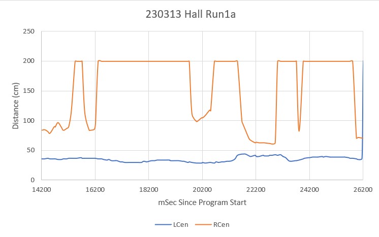
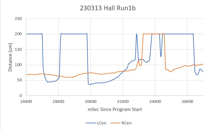
This morning I uploaded _V5 to the robot and set it loose on my ‘two wall changes’ test configuration, and I’m happy to say that it performed identically to what it was doing prior to the changes described above. It even failed in almost exactly the same way at the end with the ”aggressive spin move” behavior (which I’m almost sure is due to calling SpinTurn() with a very large rotation value).
24 August 2023 Update:
I think I now have the ‘right-left-right’ wall switching algorithm working fairly well now, and the actual code is starting to look a lot like the flow diagram posted above. The latest change was to move left/right wall selection code out of loop() and into ‘HandleAnomalousConditions()’, bringing the code more into line with the flow diagram. Now the robot goes through both transitions (right-to-left and left-to-right) with no problem and no duplicative steps – yay!
Stay tuned,
Frank