/*
Name: FourWD_WallTrackTest_V3.ino
Created: 9/3/2021 6:41:37 PM
Author: FRANKNEWXPS15\Frank
*/
/*
Name: FourWD_WallTrackTest_V2.ino
Created: 8/7/2021 2:23:38 PM
Author: FRANKNEWXPS15\Frank
*/
#pragma region INCLUDES
#include <elapsedMillis.h>
#include <PrintEx.h> //allows printf-style printout syntax
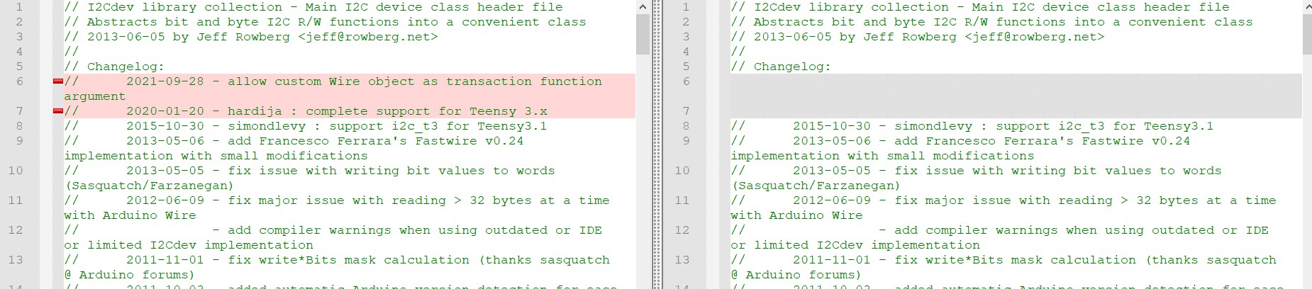
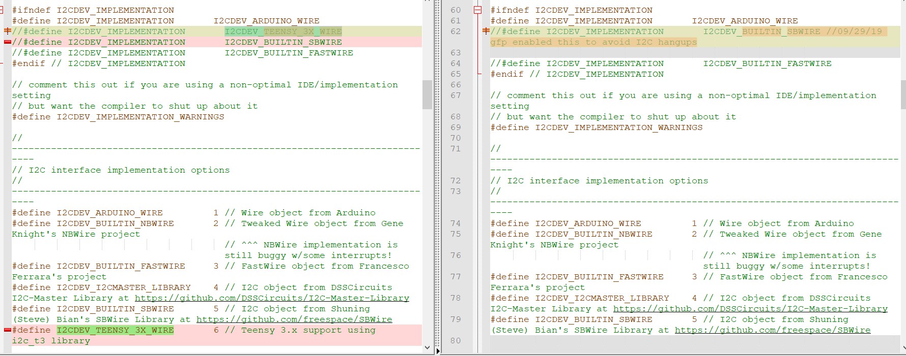
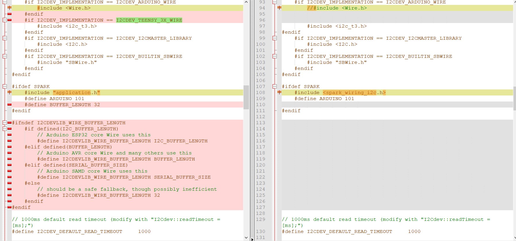
#include "MPU6050_6Axis_MotionApps_V6_12.h" //changed to this version 10/05/19
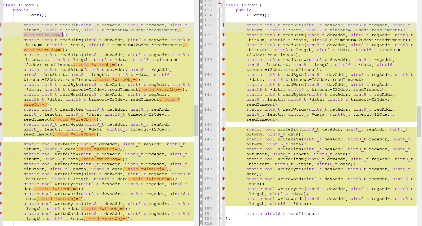
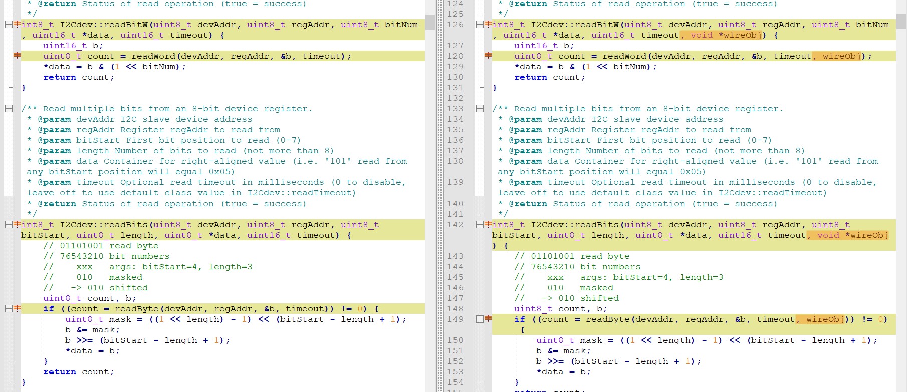
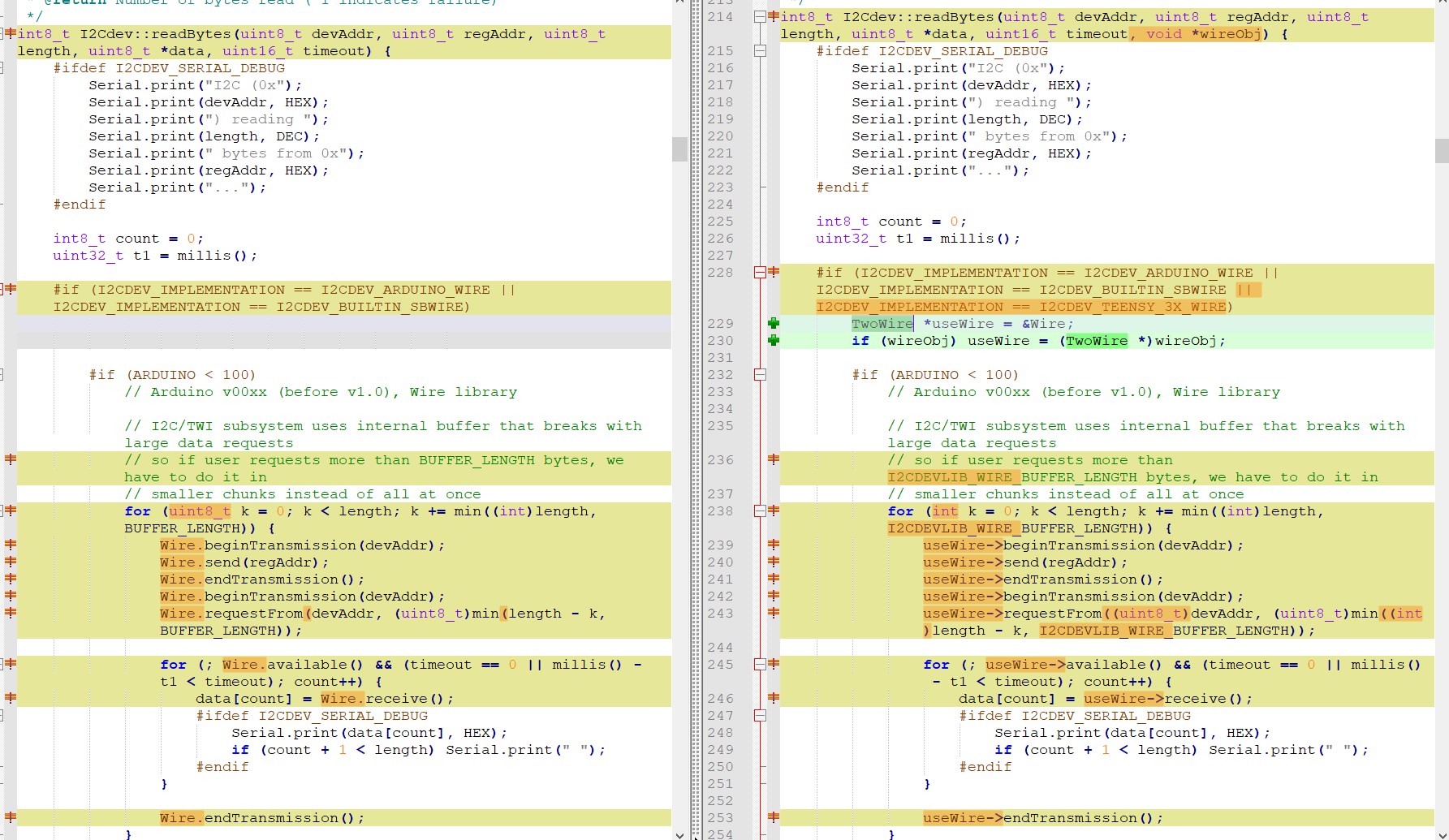
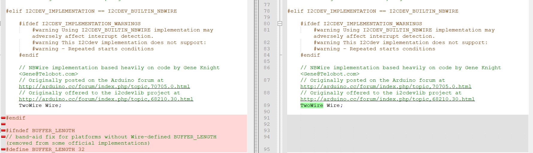
#include "I2Cdev.h" //this includes Wire.h
#include "I2C_Anything.h" //needed for sending float data over I2C
#include <PID_v2.h> //moved here 02/09/19
#include <MemoryFree.h>;
#pragma endregion Includes
#pragma region DEFINES
#define MPU6050_I2C_ADDR 0x68 //08/09/21 now using default 0x68 addr, since RTC has been removed
//#define DISTANCES_ONLY //added 11/14/18 to just display distances in infinite loop
//#define NO_MOTORS //07/18/21 debug
//#define NO_LIDAR
//#define MPU6050_CCW_INCREASES_YAWVAL //added 12/05/19
#pragma endregion DEFINES
#pragma region PRE_SETUP
StreamEx mySerial = Serial; //added 03/18/18 for printf-style printing
MPU6050 mpu(MPU6050_I2C_ADDR); //06/23/18 chg to AD0 high addr, using INT connected to Mega pin 2 (INT0)
volatile int frontdistval = 0; //10/10/20 chg to volatile
volatile double frontvar = 0; //08/11/20 now updated in timer1 ISR
const int MAX_FRONT_DISTANCE_CM = 400;
const int FRONT_DIST_AVG_WINDOW_SIZE = 3; //moved here & renamed 04/28/19
const int FRONT_DIST_ARRAY_SIZE = 50; //11/22/20 doubled to acct for 10Hz update rate
uint16_t aFrontDist[FRONT_DIST_ARRAY_SIZE]; //04/18/19 rev to use uint16_t vs byte
//11/03/18 added for new incremental variance calc
double Front_Dist_PrevVar = 0;
double Front_Dist_PrevVMean = 0;
#pragma region MOTOR_PINS
//09/11/20 Now using two Adafruit DRV8871 drivers for all 4 motors
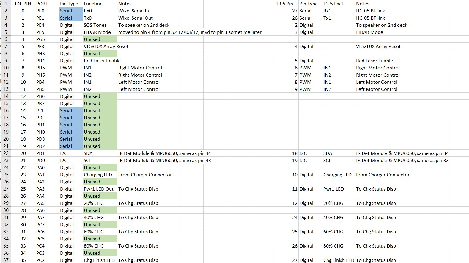
const int In1_Left = 10;
const int In2_Left = 11;
const int In1_Right = 8;
const int In2_Right = 9;
#pragma endregion Motor Pin Assignments
#pragma region MISC_PIN_ASSIGNMENTS
const int RED_LASER_DIODE_PIN = 7;
const int LIDAR_MODE_PIN = 4; //mvd here 01/10/18
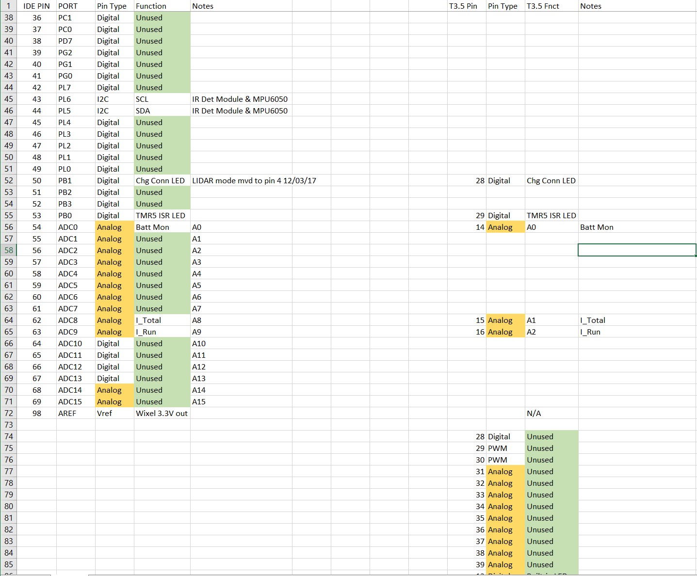
const int BATT_MON_PIN = A1;//BATT Monitor and IR Detector pin assignments added 01/30/17
#pragma endregion MISC_PIN_ASSIGNMENTS
#pragma region MOTOR_PARAMETERS
//drive wheel speed parameters
const int MOTOR_SPEED_FULL = 200; //range is 0-255
const int MOTOR_SPEED_MAX = 255; //range is 0-255
const int MOTOR_SPEED_HALF = 127; //range is 0-255
const int MOTOR_SPEED_QTR = 75; //added 09/25/20
const int MOTOR_SPEED_LOW = 50; //added 01/22/15
const int MOTOR_SPEED_OFF = 0; //range is 0-255
//drive wheel direction constants
const boolean FWD_DIR = true;
const boolean REV_DIR = !FWD_DIR;
const bool TURNDIR_CCW = true;
const bool TURNDIR_CW = false;
//Motor direction variables
boolean bLeftMotorDirIsFwd = true;
boolean bRightMotorDirIsFwd = true;
bool bIsForwardDir = true; //default is foward direction
#pragma endregion Motor Parameters
#pragma region HEADING_AND_RATE_BASED_TURN_PARAMETERS
elapsedMillis MsecSinceLastTurnRateUpdate;
const int MAX_PULSE_WIDTH_MSEC = 100;
const int MIN_PULSE_WIDTH_MSEC = 0;
const int MAX_SPIN_MOTOR_SPEED = 250;
const int MIN_SPIN_MOTOR_SPEED = 50;
//const int TURN_RATE_UPDATE_INTERVAL_MSEC = 30;
//const int TURN_RATE_UPDATE_INTERVAL_MSEC = 60;
const int TURN_RATE_UPDATE_INTERVAL_MSEC = 100;
double Prev_HdgDeg = 0;
float tgt_deg;
float timeout_sec;
//05/31/21 latest & greatest PID values
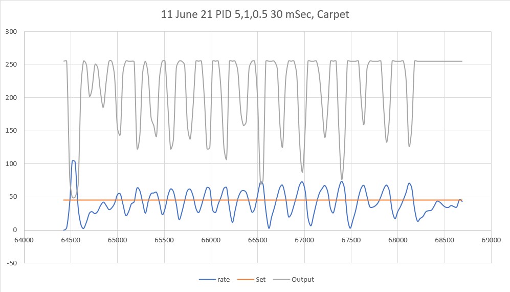
double TurnRate_Kp = 5.0;
double TurnRate_Ki = 1;
//double TurnRate_Kd = 0.5;
//double TurnRate_Kd = 1.5;
double TurnRate_Kd = 2.5;
double TurnRatePIDSetPointDPS, TurnRatePIDOutput;
double TurnRatePIDInput = 15.f;
PID TurnRatePID(&TurnRatePIDInput, &TurnRatePIDOutput, &TurnRatePIDSetPointDPS, TurnRate_Kp, TurnRate_Ki, TurnRate_Kd, DIRECT);
const float HDG_NEAR_MATCH_VAL = 0.8; //slow the turn down here
const float HDG_FULL_MATCH_VAL = 0.99; //stop the turn here //rev 05/17/20
const float HDG_MIN_MATCH_VAL = 0.6; //added 09/08/18: don't start checking slope until turn is well started
#pragma endregion HEADING_AND_RATE_BASED_TURN_PARAMETERS
#pragma region MPU6050_SUPPORT
uint8_t mpuIntStatus; // holds actual interrupt status byte from MPU. Used in Homer's Overflow routine
uint8_t devStatus; // return status after each device operation (0 = success, !0 = error)
uint16_t packetSize; // expected DMP packet size (default is 42 bytes)
uint16_t fifoCount; // count of all bytes currently in FIFO
uint8_t fifoBuffer[64]; // FIFO storage buffer
// orientation/motion vars
Quaternion q; // [w, x, y, z] quaternion container
VectorInt16 aa; // [x, y, z] accel sensor measurements
VectorInt16 aaReal; // [x, y, z] gravity-free accel sensor measurements
VectorInt16 aaWorld; // [x, y, z] world-frame accel sensor measurements
VectorFloat gravity; // [x, y, z] gravity vector
float euler[3]; // [psi, theta, phi] Euler angle container
float ypr[3]; // [yaw, pitch, roll] yaw/pitch/roll container and gravity vector
int GetPacketLoopCount = 0;
int OuterGetPacketLoopCount = 0;
//MPU6050 status flags
bool bMPU6050Ready = true;
bool dmpReady = false; // set true if DMP init was successful
volatile float IMUHdgValDeg = 0; //updated by UpdateIMUHdgValDeg()//11/02/20 now updated in ISR
bool bFirstTime = true;
#pragma endregion MPU6050 Support
#pragma region WALL_FOLLOW_SUPPORT
const int WALL_OFFSET_TRACK_Kp = 100;
const int WALL_OFFSET_TRACK_Ki = 0;
const int WALL_OFFSET_TRACK_Kd = 0;
//const double WALL_OFFSET_TRACK_SETPOINT_LIMIT = 0.3;
//const double WALL_OFFSET_TRACK_SETPOINT_LIMIT = 0.4;
//const double WALL_OFFSET_TRACK_SETPOINT_LIMIT = 0.5;
//const double WALL_OFFSET_TRACK_SETPOINT_LIMIT = 0.15;
const double WALL_OFFSET_TRACK_SETPOINT_LIMIT = 0.25;
double WallTrackSteerVal, WallTrackOutput, WallTrackSetPoint;
const int CHG_CONNECT_LED_PIN = 50; //12/16/20 added for debug
//const int WALL_OFFSET_TGTDIST_CM = 30;
const int WALL_OFFSET_TGTDIST_CM = 40;
double LeftSteeringVal, RightSteeringVal; //added 08/06/20
const int WALL_TRACK_UPDATE_INTERVAL_MSEC = 50;
//const int WALL_TRACK_UPDATE_INTERVAL_MSEC = 30;
const int WALL_OFFSET_APPR_ANGLE_MINDEG = 30;//added 09/08/21
#pragma endregion WALL_FOLLOW_SUPPORT
#pragma region VL53L0X LIDAR SUPPORT
//VL53L0X Sensor data values
//11/05/20 revised to make all volatile
volatile int Lidar_RightFront;
volatile int Lidar_RightCenter;
volatile int Lidar_RightRear;
volatile int Lidar_LeftFront;
volatile int Lidar_LeftCenter;
volatile int Lidar_LeftRear;
volatile int Lidar_Rear; //added 10/24/20
bool bVL53L0X_TeensyReady = false; //11/10/20 added to prevent bad data reads during Teensy setup()
enum VL53L0X_REQUEST
{
VL53L0X_READYCHECK, //added 11/10/20 to prevent bad reads during Teensy setup()
VL53L0X_CENTERS_ONLY,
VL53L0X_RIGHT,
VL53L0X_LEFT,
VL53L0X_ALL, //added 08/06/20, replaced VL53L0X_BOTH 10/31/20
VL53L0X_REAR_ONLY //added 10/24/20
};
const int VL53L0X_I2C_SLAVE_ADDRESS = 0x20; ////Teensy 3.5 VL53L0X ToF LIDAR controller
#pragma endregion VL53L0X LIDAR SUPPORT
#pragma region TIMER_ISR
#define TIMER_INT_OUTPUT_PIN 53 //scope monitor pin
bool GetRequestedVL53l0xValues(VL53L0X_REQUEST which);
volatile bool bTimeForNavUpdate = false;
const int TIMER5_INTERVAL_MSEC = 100; //05/15/21 added to eliminate magic number
int GetFrontDistCm();
ISR(TIMER5_COMPA_vect) //timer5 interrupt 5Hz
{
digitalWrite(TIMER_INT_OUTPUT_PIN, HIGH);//so I can monitor interrupt timing
delayMicroseconds(30); //leave in - so can see even with NO_STUCK defined
bTimeForNavUpdate = true;
//11/2/20 have to re-enable interrupts for I2C comms to work
interrupts();
GetRequestedVL53l0xValues(VL53L0X_ALL); //11/2/20 update all distances every 100mSec
noInterrupts();
frontdistval = GetFrontDistCm();
digitalWrite(TIMER_INT_OUTPUT_PIN, LOW);//so I can monitor interrupt timing
}
#pragma endregion TIMER_ISR
#pragma endregion PRE_SETUP
#pragma region BATTCONSTS
//03/10/15 added for battery charge level monitoring
//const int LOW_BATT_THRESH_VOLTS = 7.4; //50% chg per http://batteryuniversity.com/learn/article/lithium_based_batteries
//const int LOW_BATT_THRESH_VOLTS = 8.4; //07/10/20 temp debug settingr//50% chg per http://batteryuniversity.com/learn/article/lithium_based_batteries
const float LOW_BATT_THRESH_VOLTS = 8.4; //12/18/20 chg to float to fix bug
const int MAX_AD_VALUE = 1023;
//const long BATT_CHG_TIMEOUT_SEC = 36000; //10 HRS
const long BATT_CHG_TIMEOUT_SEC = 3600; //12/28/20 for test only
const float DEAD_BATT_THRESH_VOLTS = 6; //added 01/24/17
const float FULL_BATT_VOLTS = 8.4; //added 03/17/18. Chg to 8.4 03/05/20
const int MINIMUM_CHARGE_TIME_SEC = 10; //added 04/01/18
const float VOLTAGE_TO_CURRENT_RATIO = 0.75f; //Volts/Amp rev 03/01/19. Used for both 'Total' and 'Run' sensors
const float FULL_BATT_CURRENT_THRESHOLD = 0.5; //amps chg to 0.5A 03/02/19 per https://www.fpaynter.com/2019/03/better-battery-charging-for-wall-e2/
const int CURRENT_AVERAGE_NUMBER = 10; //added 03/01/19
const int VOLTS_AVERAGE_NUMBER = 5; //added 03/01/19
const int IR_HOMING_TELEMETRY_SPACING_MSEC = 200; //added 04/23/20
const float ZENER_VOLTAGE_OFFSET = 5.84; //measured zener voltage
const float ADC_REF_VOLTS = 3.3; //03/27/18 now using analogReference(EXTERNAL) with Teensy 3.3V connected to AREF
#pragma endregion BATTCONST
void setup()
{
Serial.begin(115200);
#pragma region MPU6050
mySerial.printf("\nChecking for MPU6050 IMU at I2C Addr 0x%x\n", MPU6050_I2C_ADDR);
mpu.initialize();
// verify connection
Serial.println(mpu.testConnection() ? F("MPU6050 connection successful") : F("MPU6050 connection failed"));
float StartSec = 0; //used to time MPU6050 init
Serial.println(F("Initializing DMP..."));
devStatus = mpu.dmpInitialize();
// make sure it worked (returns 0 if successful)
if (devStatus == 0)
{
// turn on the DMP, now that it's ready
Serial.println(F("Enabling DMP..."));
mpu.setDMPEnabled(true);
// set our DMP Ready flag so the main loop() function knows it's okay to use it
Serial.println(F("DMP ready! Waiting for MPU6050 drift rate to settle..."));
dmpReady = true;
// get expected DMP packet size for later comparison
packetSize = mpu.dmpGetFIFOPacketSize();
mySerial.printf("Just after MPU6050 Init\n");
mySerial.printf("Calibrating...\n");
mpu.CalibrateGyro(); //using default value of 15
mySerial.printf("Retrieving Calibration Values\n\n");
mpu.PrintActiveOffsets();
//loop heading display until stabilized
mySerial.printf("\nMsec\tHdg\n");
UpdateIMUHdgValDeg();
Prev_HdgDeg = IMUHdgValDeg;
delay(100);
UpdateIMUHdgValDeg();
mySerial.printf("%lu\t%2.3f\t%2.3f\n", millis(), IMUHdgValDeg, Prev_HdgDeg);
while (abs(IMUHdgValDeg - Prev_HdgDeg) > 0.1f)
{
mySerial.printf("%lu\t%2.3f\n", millis(), IMUHdgValDeg);
Prev_HdgDeg = IMUHdgValDeg;
delay(100);
UpdateIMUHdgValDeg();
}
StartSec = millis() / 1000.f;
mySerial.printf("MPU6050 Ready at %2.2f Sec with delta = %2.3f\n", StartSec, IMUHdgValDeg - Prev_HdgDeg);
bMPU6050Ready = true;
delay(1000);
}
else //MPU6050 Init failed for some reason
{
// ERROR!
// 1 = initial memory load failed
// 2 = DMP configuration updates failed
// (if it's going to break, usually the code will be 1)
Serial.print(F("DMP Initialization failed (code "));
Serial.print(devStatus);
Serial.println(F(")"));
//08/29/21 print out battery voltage on failure
float batV = GetBattVoltage();
mySerial.printf("Battery Voltage = %2.2f\n", batV);
bMPU6050Ready = false;
}
#pragma endregion MPU6050
#pragma region PIN_INITIALIZATION
pinMode(LIDAR_MODE_PIN, INPUT); // Set LIDAR input monitor pin
#pragma endregion PIN_INITIALIZATION
//#pragma region TIMER_INTERRUPT
// //09/18/20 can't use Timer1 cuz doing so conflicts with PWM on pins 10-12
// cli();//stop interrupts
// TCCR5A = 0;// set entire TCCR5A register to 0
// TCCR5B = 0;// same for TCCR5B
// TCNT5 = 0;//initialize counter value to 0
//
// // 06/15/21 rewritten to use defined interval constant rather than magic number
// //10/11/20 chg timer interval to 10Hz vs 5
// //OCR5A = 1562;// = (16*10^6) / (10*1024) - 1 (must be <65536)
// int ocr5a = (16 * 1e6) / ((1000 / TIMER5_INTERVAL_MSEC) * 1024) - 1;
// mySerial.printf("ocr5a = %d\n", ocr5a);
// OCR5A = ocr5a;
// TCCR5B |= (1 << WGM52);// turn on CTC mode
// TCCR5B |= (1 << CS52) | (1 << CS50);// Set CS10 and CS12 bits for 1024 prescaler
// TIMSK5 |= (1 << OCIE5A);// enable timer compare interrupt
// sei();//allow interrupts
// pinMode(TIMER_INT_OUTPUT_PIN, OUTPUT);
//#pragma endregion TIMER_INTERRUPT
//
// //02/08/21 mvd below ISR enable so this section can use ISR-generated VL53L0X distances
#pragma region VL53L0X_TEENSY
mySerial.printf("Checking for Teensy 3.5 VL53L0X Controller at I2C addr 0x%x\n", VL53L0X_I2C_SLAVE_ADDRESS);
while (!bVL53L0X_TeensyReady)
{
Wire.beginTransmission(VL53L0X_I2C_SLAVE_ADDRESS);
bVL53L0X_TeensyReady = (Wire.endTransmission() == 0);
//mySerial.printf("%lu: VL53L0X Teensy Not Avail...\n", millis());
delay(100);
}
mySerial.printf("Teensy available at %lu with bVL53L0X_TeensyReady = %d. Waiting for Teensy setup() to finish\n", millis(), bVL53L0X_TeensyReady);
WaitForVL53L0XTeensy();
//mySerial.printf("VL53L0X Teensy Ready at %lu\n\n", millis());
#pragma endregion VL53L0X_TEENSY
mySerial.printf("Just after WaitForVL53L0XTeensy();\n");
//11/14/18 added this section for distance printout only
//08/06/20 revised for VL53L0X support
#ifdef DISTANCES_ONLY
//TIMSK5 = 0;
digitalWrite(RED_LASER_DIODE_PIN, HIGH); //enable the front laser dot
mySerial.printf("\n------------ DISTANCES ONLY MODE!!! -----------------\n\n");
int i = 0; //added 09/20/20 for in-line header display
mySerial.printf("Msec\tLFront\tLCenter\tLRear\tRFront\tRCenter\tRRear\tFront\tRear\n");
while (true)
{
//if (bTimeForNavUpdate)
//{
// bTimeForNavUpdate = false;
//09/20/20 re-display the column headers
//if (++i % 20 == 0)
//{
// mySerial.printf("\nMsec\tLFront\tLCenter\tLRear\tRFront\tRCenter\tRRear\tFront\tRear\n");
//}
//commented out 02/02/21 - now done in ISR
GetRequestedVL53l0xValues(VL53L0X_ALL);
frontdistval = GetFrontDistCm();
mySerial.printf("%lu\t%d\t%d\t%d\t%d\t%d\t%d\t%d\t%d\n",
millis(), Lidar_LeftFront, Lidar_LeftCenter, Lidar_LeftRear,
Lidar_RightFront, Lidar_RightCenter, Lidar_RightRear, frontdistval, Lidar_Rear);
//}
delay(50);
}
//TIMSK5 |= (1 << OCIE5A);// enable timer compare interrupt
#endif // DISTANCES_ONLY
#pragma region L/R/FRONT DISTANCE ARRAYS
//09/20/20 have to do this for parallel finding to go the right way
Serial.println(F("Initializing Left, Right, Front Distance Arrays..."));
#ifndef NO_PINGS
//03/30/21 moved FrontDistArray init ahead of left/right dist init to prevent inadvertent 'stuck' detection
Serial.println(F("Initializing Front Distance Array"));
InitFrontDistArray(); //08/12/20 code extracted to fcn so can call elsewhere
//Serial.println(F("Updating Left\tRight Distance Arrays"));
//for (size_t i = 0; i < LR_DIST_ARRAY_SIZE; i++)
//{
// delay(100); //ensure enough time for ISR to update distances
// mySerial.printf("%d\t%d\n", Lidar_LeftCenter, Lidar_RightCenter);
// UpdateLRDistanceArrays(Lidar_LeftCenter, Lidar_RightCenter);
//}
//Serial.println(F("Updating Rear Distance Arrays"));
//InitRearDistArray();
//mySerial.printf("Initial rear prev_mean, prev_var = %2.2f, %2.2f\n",
// Rear_Dist_PrevMean, Rear_Dist_PrevVar);
#else
Serial.println(F("Distance Sensors Disabled"));
#endif // NO_PINGS
#pragma endregion L/R/FRONT DISTANCE ARRAYS
#pragma region WALL_TRACK_TEST
//mySerial.printf("End of test - Stopping!\n");
////while (true)
////{
//// CheckForUserInput();
////}
//StopBothMotors();
//Serial.println(F("Setting Kp value"));
//const int bufflen = 80;
//char buff[bufflen];
//memset(buff, 0, bufflen);
float OffsetCm;
float Kp, Ki, Kd;
//const char s[2] = ",";
//char* token;
////consume CR/LF chars
//while (Serial.available() > 0)
//{
// int byte = Serial.read();
// mySerial.printf("consumed %d\n", byte);
//}
//while (!Serial.available())
//{
//}
//Serial.readBytes(buff, bufflen);
//mySerial.printf("%s\n", buff);
///* extract Kp */
//token = strtok(buff, s);
//Kp = atof(token);
///* extract Ki */
//token = strtok(NULL, s);
//Ki = atof(token);
///* extract Kd */
//token = strtok(NULL, s);
//Kd = atof(token);
///* extract Offset in cm */
//token = strtok(NULL, s);
//OffsetCm = atof(token);
//mySerial.printf("Kp,Ki,Kd,OffsetCm = %2.2f, %2.2f, %2.2f, %2.2f\n",
// Kp, Ki, Kd, OffsetCm);5
//Kp = 300;
//Kp = 500;
//Kp = 700;
//Kp = 500;
//Kp = 400;
Kp = 300;
Ki = 0;
//Ki = 10;
//Kd = 0;
//Kd = 100;
//Kd = 200;
Kd = 300;
OffsetCm = 40;
//TrackLeftWallOffset(Kp, Ki, Kd, OffsetCm);
//TrackLeftWallOffset(1, 1, 1, 1); //09/05/21 params not used
TrackRightWallOffset(Kp, Ki, Kd, OffsetCm);
// //mySerial.printf("Rdist\tCdist\tFdist\tsteer\toffang\n");
// //while (true)
// //{
// // //double offangdeg = GetSteeringAngle(Lidar_LeftCenter / 10, LeftSteeringVal);
// // double offangdeg = GetSteeringAngle(LeftSteeringVal); //06/25/21 chg to mm vs cm
// // mySerial.printf("%d\t%d\t%d\t%2.4f\t%2.2f\n", Lidar_LeftRear, Lidar_LeftCenter, Lidar_LeftFront, LeftSteeringVal, offangdeg);
// // delay(1000);
// //}
#pragma endregion WALL_TRACK_TEST
//mySerial.printf("Msec\tHdg\n");
//RunBothMotors(true, MOTOR_SPEED_HALF, MOTOR_SPEED_HALF);
}
void loop()
{
int turndeg = 45;
mySerial.printf("CCW turn, %d deg\n", turndeg);
//SpinTurn(true, turndeg, 45);
//delay(1000);
SpinTurn(true, turndeg, 30);
//ShowMultipleHeadingMeasurements(50);
StopBothMotors();
delay(500);
//mySerial.printf("CW turn, %d deg\n", turndeg);
//SpinTurn(false, turndeg, 45);
//delay(1000);
SpinTurn(false, turndeg, 30);
//ShowMultipleHeadingMeasurements(50);
StopBothMotors();
delay(500);
turndeg = 90;
//mySerial.printf("CCW turn, %d deg\n", turndeg);
//SpinTurn(true, turndeg, 45);
delay(1000);
SpinTurn(true, turndeg, 30);
//ShowMultipleHeadingMeasurements(50);
StopBothMotors();
delay(500);
//mySerial.printf("CW turn, %d deg\n", turndeg);
//SpinTurn(false, turndeg, 45);
delay(1000);
SpinTurn(false, turndeg, 30);
//ShowMultipleHeadingMeasurements(50);
StopBothMotors();
delay(500);
//mySerial.printf("Done with turning tests. Free memory = %d\n", freeMemory());
}
#pragma region VL53L0X_SUPPORT
bool GetRequestedVL53l0xValues(VL53L0X_REQUEST which)
{
//Purpose: Obtain VL53L0X ToF sensor data from Teensy sensor handler
//Inputs:
// which = VL53L0X_REQUEST value denoting which combination of value to retrieve
// VL53L0X_CENTERS_ONLY -> Just the left/right center sensor values
// VL53L0X_RIGHT -> All three right sensor values, in front/center/rear order
// VL53L0X_LEFT -> All three left sensor values, in front/center/rear order
// VL53L0X_ALL -> All seven sensor values, in left/right front/center/rear/rear order
// VL53L0X_REAR_ONLY -> added 10/24/20 Just the rear sensor reading
//Outputs:
// Requested sensor values, obtained via I2C from the VL53L0X sensor handler
// Returns TRUE if data retrieval successful, otherwise FALSE
//Plan:
// Step1: Send request to VL53L0X handler
// Step2: get the requested data
//Notes:
// Copied from FourWD_WallE2_V4.ino's IsIRBeamAvail() and adapted
// 08/05/20 added a VL53L0X_ALL request type
// 01/24/21 added error detection/reporting
//Step1: Send request to VL53L0X handler
//DEBUG!!
//mySerial.printf("Sending %d to slave\n", which);
//DEBUG!!
//mySerial.printf("In GetRequestedVL53l0xValues(%d)\n", (int)which);
Wire.beginTransmission(VL53L0X_I2C_SLAVE_ADDRESS);
I2C_writeAnything((uint8_t)which);
Wire.endTransmission();
//Step2: get the requested data
int readResult = 0;
int data_size = 0;
switch (which)
{
case VL53L0X_READYCHECK: //11/10/20 added to prevent bad reads during Teensy setup()
Wire.requestFrom(VL53L0X_I2C_SLAVE_ADDRESS, (int)(sizeof(bVL53L0X_TeensyReady)));
readResult = I2C_readAnything(bVL53L0X_TeensyReady);
break;
case VL53L0X_CENTERS_ONLY:
//just two data values needed here
data_size = 2 * sizeof(int);
Wire.requestFrom(VL53L0X_I2C_SLAVE_ADDRESS, (int)(2 * sizeof(Lidar_RightCenter)));
readResult = I2C_readAnything(Lidar_RightCenter);
if (readResult > 0)
{
I2C_readAnything(Lidar_LeftCenter);
}
//DEBUG!!
//mySerial.printf("VL53L0X_CENTERS_ONLY case: Got LC/RC = %d, %d\n", Lidar_LeftCenter, Lidar_RightCenter);
//DEBUG!!
break;
case VL53L0X_RIGHT:
//four data values needed here
data_size = 3 * sizeof(int) + sizeof(float);
//DEBUG!!
//mySerial.printf("data_size = %d\n", data_size);
//DEBUG!!
Wire.requestFrom(VL53L0X_I2C_SLAVE_ADDRESS, data_size);
readResult = I2C_readAnything(Lidar_RightFront);
if (readResult > 0)
{
readResult = I2C_readAnything(Lidar_RightCenter);
}
if (readResult > 0)
{
readResult = I2C_readAnything(Lidar_RightRear);
}
if (readResult > 0)
{
readResult = I2C_readAnything(RightSteeringVal);
}
//DEBUG!!
//mySerial.printf("VL53L0X_RIGHT case: Got L/C/R/S = %d, %d, %d, %3.2f\n",
// Lidar_RightFront, Lidar_RightCenter, Lidar_RightRear, ToFSteeringVal);
//DEBUG!!
break;
case VL53L0X_LEFT:
//four data values needed here
data_size = 3 * sizeof(int) + sizeof(float);
Wire.requestFrom(VL53L0X_I2C_SLAVE_ADDRESS, data_size);
readResult = I2C_readAnything(Lidar_LeftFront);
if (readResult > 0)
{
readResult = I2C_readAnything(Lidar_LeftCenter);
}
if (readResult > 0)
{
readResult = I2C_readAnything(Lidar_LeftRear);
}
if (readResult > 0)
{
readResult = I2C_readAnything(LeftSteeringVal);
}
//DEBUG!!
//mySerial.printf("VL53L0X_RIGHT case: Got L/C/R/S = %d, %d, %d, %3.2f\n",
// Lidar_LeftFront, Lidar_LeftCenter, Lidar_LeftRear, ToFSteeringVal);
//DEBUG!!
break;
case VL53L0X_ALL: //added 08/05/20, chg to VL53L0X_ALL 10/31/20
//nine data values needed here - 7 ints and 2 floats
data_size = 7 * sizeof(int) + 2 * sizeof(float); //10/31/20 added rear distance
//mySerial.printf("In VL53L0X_ALL case with data_size = %d\n", data_size);
Wire.requestFrom(VL53L0X_I2C_SLAVE_ADDRESS, data_size);
//Lidar_LeftFront
readResult = I2C_readAnything(Lidar_LeftFront);
if (readResult != sizeof(Lidar_LeftFront))
{
mySerial.printf("Error reading Lidar_LeftFront\n");
}
//Lidar_LeftCenter
readResult = I2C_readAnything(Lidar_LeftCenter);
if (readResult != sizeof(Lidar_LeftCenter))
{
mySerial.printf("Error reading Lidar_LeftCenter\n");
}
//Lidar_LeftRear
readResult = I2C_readAnything(Lidar_LeftRear);
if (readResult != sizeof(Lidar_LeftRear))
{
mySerial.printf("Error reading Lidar_LeftRear\n");
}
//LeftSteeringVal
readResult = I2C_readAnything(LeftSteeringVal);
if (readResult != sizeof(LeftSteeringVal))
{
mySerial.printf("Error reading LeftSteeringVal\n");
}
//Lidar_RightFront
readResult = I2C_readAnything(Lidar_RightFront);
if (readResult != sizeof(Lidar_RightFront))
{
mySerial.printf("Error reading Lidar_RightFront\n");
}
//Lidar_RightCenter
readResult = I2C_readAnything(Lidar_RightCenter);
if (readResult != sizeof(Lidar_RightCenter))
{
mySerial.printf("Error reading Lidar_RightCenter\n");
}
//Lidar_RightRear
readResult = I2C_readAnything(Lidar_RightRear);
if (readResult != sizeof(Lidar_RightRear))
{
mySerial.printf("Error reading Lidar_RightRear\n");
}
//RightSteeringVal
readResult = I2C_readAnything(RightSteeringVal);
if (readResult != sizeof(RightSteeringVal))
{
mySerial.printf("Error reading LeftSteeringVal\n");
}
//Lidar_Rear
readResult = I2C_readAnything(Lidar_Rear);
if (readResult != sizeof(Lidar_Rear))
{
mySerial.printf("Error reading Lidar_Rear\n");
}
//mySerial.printf("%lu: VL53l0x - %d, %d, %d, %d, %d, %d, %d\n",
// millis(),
// Lidar_LeftFront, Lidar_LeftCenter, Lidar_LeftRear,
// Lidar_RightFront, Lidar_RightCenter, Lidar_RightRear,
// Lidar_Rear);
break; //10/31/20 bugfix
case VL53L0X_REAR_ONLY:
//just ONE data value needed here
data_size = sizeof(int);
Wire.requestFrom(VL53L0X_I2C_SLAVE_ADDRESS, (int)(sizeof(Lidar_Rear)));
readResult = I2C_readAnything(Lidar_Rear);
//DEBUG!!
//mySerial.printf("VL53L0X_REAR_ONLY case: Got Rear = %d\n", Lidar_Rear);
//DEBUG!!
break;
default:
break;
}
return readResult > 0; //this is true only if all reads succeed
}
void WaitForVL53L0XTeensy()
{
bVL53L0X_TeensyReady = false;
while (!bVL53L0X_TeensyReady)
{
GetRequestedVL53l0xValues(VL53L0X_READYCHECK); //this updates bVL53L0X_TeensyReady
//mySerial.printf("%lu: got %d from VL53L0X Teensy\n", millis(), bVL53L0X_TeensyReady);
delay(100);
}
Serial.print(F("Teensy setup() finished at ")); Serial.printf("%lu mSec\n", millis());
//now try to get a VL53L0X measurement
//11/08/20 rev to loop until all distance sensors provide valid data
//mySerial.printf("Msec\tLFront\tLCtr\tLRear\tRFront\tRCtr\tRRear\tRear\n");
GetRequestedVL53l0xValues(VL53L0X_ALL); //09/04/21 now doing directly w/o ISR
//mySerial.printf("%lu: %d\t%d\t%d\t%d\t%d\t%d\t%d\n",
// millis(), Lidar_LeftFront, Lidar_LeftCenter, Lidar_LeftRear,
// Lidar_RightFront, Lidar_RightCenter, Lidar_RightRear, Lidar_Rear);
while (Lidar_LeftFront <= 0 || Lidar_LeftCenter <= 0 || Lidar_LeftRear <= 0
|| Lidar_LeftFront <= 0 || Lidar_LeftCenter <= 0 || Lidar_LeftRear <= 0
|| Lidar_Rear <= 0)
{
////values updated 10 times/sec in ISR
mySerial.printf("%lu: %d\t%d\t%d\t%d\t%d\t%d\t%d\n",
millis(), Lidar_LeftFront, Lidar_LeftCenter, Lidar_LeftRear,
Lidar_RightFront, Lidar_RightCenter, Lidar_RightRear, Lidar_Rear);
delay(100);
GetRequestedVL53l0xValues(VL53L0X_ALL); //09/04/21 now doing directly w/o ISR
}
mySerial.printf("VL53L0X Teensy Ready at %lu\n\n", millis());
}
double GetSteeringAngle(double steerval)
{
//Purpose: Convert a steering angle into the equivalent off-parallel orientation in degrees
//Inputs:
// steerval = double value denoting current steering value
// Notes:
// 06/27/21 now steering_val/off_angle slope is a constant 0.0175
const double slopeval = 0.0175;
double offparalleldeg = steerval / slopeval; //e.g. for steerval = -0.187 @ 10cm offset, returns +21deg
//mySerial.printf("GetSteeringAngle(%d, %2.4f): slopeval = %2.4f, res %2.2f\n", ctrdist_cm, steerval, slopeval, offparalleldeg);
return offparalleldeg;
}
#pragma endregion VL53L0X_SUPPORT
#pragma region LIDAR_SUPPORT
//11/05/15 added to get LIDAR measurement
int GetFrontDistCm()
{
//Notes:
// 12/05/15 chg to MODE line vs I2C
// 01/06/16 rev to return avg of prev distances on error
#ifndef NO_LIDAR
unsigned long pulse_width;
int LIDARdistCm;
pulse_width = pulseIn(LIDAR_MODE_PIN, HIGH); // Count how long the pulse is high in microseconds
LIDARdistCm = pulse_width / 10; // 10usec = 1 cm of distance for LIDAR-Lite
//chk for erroneous reading
if (LIDARdistCm == 0)
{
//replace with average of last three readings from aFrontDist
int avgdist = GetAvgFrontDistCm();
mySerial.printf("%lu: Error in GetFrontDistCm() - %d replaced with %d\n", millis(), LIDARdistCm, avgdist);
LIDARdistCm = avgdist;
}
//04/30/17 added limit detection/correction
LIDARdistCm = (LIDARdistCm > 0) ? LIDARdistCm : MAX_FRONT_DISTANCE_CM;
return LIDARdistCm;
#else
return 10; //safe number, I hope
#endif
}
//04/25/21 rewritten to use aFrontDist[] values
float GetAvgFrontDistCm()
{
int avgdist = 0;
for (int i = 0; i < FRONT_DIST_AVG_WINDOW_SIZE; i++)
{
//DEBUG!!
//mySerial.printf("frontdist[%d] = %d\n", FRONT_DIST_ARRAY_SIZE - 1 - i, aFrontDist[FRONT_DIST_ARRAY_SIZE - 1 - i]);
//DEBUG!!
avgdist += aFrontDist[FRONT_DIST_ARRAY_SIZE - 1 - i];
}
//DEBUG!!
//mySerial.printf("avgdisttot = %d\n", avgdist);
//DEBUG!!
avgdist = (int)((float)avgdist / (float)FRONT_DIST_AVG_WINDOW_SIZE);
//DEBUG!!
//mySerial.printf("avgdist = %d\n", avgdist);
//DEBUG!!
return avgdist;
}
//08/12/20 Extracted inline FRONT_DIST_ARRAY init code so can be called from anywhere
void InitFrontDistArray()
{
//04/01/15 initialize 'stuck detection' arrays
//06/17/20 re-wrote for better readability
//to ensure var > STUCK_FRONT_VARIANCE_THRESHOLD for first FRONT_DIST_ARRAY_SIZE loops
//array is initialized with sawtooth from 0 to MAX_FRONT_DISTANCE_CM
int newval = 0;
int bumpval = MAX_FRONT_DISTANCE_CM / FRONT_DIST_ARRAY_SIZE;
bool bgoingUp = true;
for (int i = 0; i < FRONT_DIST_ARRAY_SIZE; i++)
{
aFrontDist[i] = newval;
//DEBUG!!
//mySerial.printf("i = %d, newval = %d, aFrontdist[%d] = %d\n", i, newval, i, aFrontDist[i]);
//DEBUG!!
if (bgoingUp)
{
if (newval < MAX_FRONT_DISTANCE_CM - bumpval) //don't want newval > MAX_FRONT_DISTANCE_CM
{
newval += bumpval;
}
else
{
bgoingUp = false;
}
}
else
{
if (newval > bumpval) //don't want newval < 0
{
newval -= bumpval;
}
else
{
bgoingUp = true;
}
}
}
//04/19/19 init Front_Dist_PrevVMean & Front_Dist_PrevVar to mean/var respectively
long sum = 0;
for (int i = 0; i < FRONT_DIST_ARRAY_SIZE; i++)
{
sum += aFrontDist[i]; //adds in rest of values
}
Front_Dist_PrevVMean = (float)sum / (float)FRONT_DIST_ARRAY_SIZE;
// Step2: calc new 'brute force' variance
float sumsquares = 0;
for (int i = 0; i < FRONT_DIST_ARRAY_SIZE; i++)
{
sumsquares += (aFrontDist[i] - Front_Dist_PrevVMean) * (aFrontDist[i] - Front_Dist_PrevVMean);
}
Front_Dist_PrevVar = sumsquares / FRONT_DIST_ARRAY_SIZE;
mySerial.printf("%lu: aFrontDist Init: Front_Dist_PrevVMean = %3.2f, Front_Dist_PrevVar = %3.2f\n", millis(), Front_Dist_PrevVMean, Front_Dist_PrevVar);
frontvar = Front_Dist_PrevVar; //added 03/30/21 to prevent 'stuck' at startup
}
#pragma endregion LIDAR_SUPPORT
#pragma region MOTOR SUPPORT
//09/08/20 modified for DRV8871 motor driver
void MoveReverse(int leftspeednum, int rightspeednum)
{
//Purpose: Move in reverse direction continuously - companion to MoveAhead()
//ProvEnA_Pinnce: G. Frank Paynter 09/08/18
//Inputs:
// leftspeednum = integer denoting speed (0=stop, 255 = full speed)
// rightspeednum = integer denoting speed (0=stop, 255 = full speed)
//Outputs: both drive Motors energized with the specified speed
//Plan:
// Step 1: Set reverse direction for both wheels
// Step 2: Run both Motors at specified speeds
//Notes:
// 01/22/20 now using Adafruit DRV8871 drivers
//Step 1: Set reverse direction and speed for both wheels
SetLeftMotorDirAndSpeed(REV_DIR, leftspeednum);
SetRightMotorDirAndSpeed(REV_DIR, rightspeednum);
}
//09/08/20 modified for DRV8871 motor driver
void MoveAhead(int leftspeednum, int rightspeednum)
{
//Purpose: Move ahead continuously
//ProvEnA_Pinnce: G. Frank Paynter and Danny Frank 01/24/2014
//Inputs:
// leftspeednum = integer denoting speed (0=stop, 255 = full speed)
// rightspeednum = integer denoting speed (0=stop, 255 = full speed)
//Outputs: both drive Motors energized with the specified speed
//Plan:
// Step 1: Set forward direction for both wheels
// Step 2: Run both Motors at specified speeds
//Notes:
// 01/22/20 now using Adafruit DRV8871 drivers
//mySerial.printf("InMoveAhead(%d,%d)\n", leftspeednum, rightspeednum);
//Step 1: Set forward direction and speed for both wheels
SetLeftMotorDirAndSpeed(true, leftspeednum);
SetRightMotorDirAndSpeed(true, rightspeednum);
}
//09/08/10 modified for DRV8871 motor driver
void StopLeftMotors()
{
analogWrite(In1_Left, MOTOR_SPEED_OFF);
analogWrite(In2_Left, MOTOR_SPEED_OFF);
}
void StopRightMotors()
{
analogWrite(In1_Right, MOTOR_SPEED_OFF);
analogWrite(In2_Right, MOTOR_SPEED_OFF);
}
//09/08/20 added bool bisFwd param for DRV8871 motor driver
void RunBothMotors(bool bisFwd, int leftspeednum, int rightspeednum)
{
//Purpose: Run both Motors at left/rightspeednum speeds
//Inputs:
// speednum = speed value (0 = OFF, 255 = full speed)
//Outputs: Both Motors run for timesec seconds at speednum speed
//Plan:
// Step 1: Apply drive to both wheels
//Notes:
// 01/14/15 - added left/right speed offset for straightness compensation
// 01/22/15 - added code to restrict fast/slow values
// 01/24/15 - revised for continuous run - no timing
// 01/26/15 - speednum modifications moved to UpdateWallFollowmyMotorspeeds()
// 12/07/15 - chg args from &int to int
//Step 1: Apply drive to both wheels
//DEBUG!!
//mySerial.printf("In RunBothMotors(%s, %d,%d)\n", bisFwd? "FWD":"REV", leftspeednum, rightspeednum);
//DEBUG!!
SetLeftMotorDirAndSpeed(bisFwd, leftspeednum);
SetRightMotorDirAndSpeed(bisFwd, rightspeednum);
}
void RunBothMotorsBidirectional(int leftspeed, int rightspeed)
{
//Purpose: Accommodate the need for independent bidirectional wheel motion
//Inputs:
// leftspeed - integer denoting left wheel speed. Positive value is fwd, negative is rev
// rightspeed - integer denoting right wheel speed. Positive value is fwd, negative is rev
//Outputs:
// left/right wheel motors direction and speed set as appropriate
//Plan:
// Step1: Set left wheel direction and speed
// Step2: Set right wheel direction and speed
//Step1: Set left wheel direction and speed
//DEBUG!!
//mySerial.printf("In RunBothMotorsBidirectional(%d, %d)\n", leftspeed, rightspeed);
if (leftspeed < 0)
{
SetLeftMotorDirAndSpeed(false, -leftspeed); //neg value ==> reverse
}
else
{
SetLeftMotorDirAndSpeed(true, leftspeed); //pos or zero value ==> fwd
}
//Step2: Set right wheel direction and speed
if (rightspeed < 0)
{
SetRightMotorDirAndSpeed(false, -rightspeed); //neg value ==> reverse
}
else
{
SetRightMotorDirAndSpeed(true, rightspeed); //pos or zero value ==> fwd
}
}
//09/08/20 added bool bisFwd param for DRV8871 motor driver
void RunBothMotorsMsec(bool bisFwd, int timeMsec, int leftspeednum, int rightspeednum)
{
//Purpose: Run both Motors for timesec seconds at speednum speed
//Inputs:
// timesec = time in seconds to run the Motors
// speednum = speed value (0 = OFF, 255 = full speed)
//Outputs: Both Motors run for timesec seconds at speednum speed
//Plan:
// Step 1: Apply drive to both wheels
// Step 2: Delay timsec seconds
// Step 3: Remove drive from both wheels.
//Notes:
// 01/14/15 - added left/right speed offset for straightness compensation
// 01/22/15 - added code to restrict fast/slow values
// 11/25/15 - rev to use motor driver class object
// 09/08/20 added bool bisFwd param for DRV8871 motor driver
RunBothMotors(bisFwd, leftspeednum, rightspeednum);
//Step 2: Delay timsec seconds
delay(timeMsec);
//Step3: Stop motors added 04/12/21
StopBothMotors();
}
//11/25/15 added for symmetry ;-).
void StopBothMotors()
{
StopLeftMotors();
StopRightMotors();
}
void SetLeftMotorDirAndSpeed(bool bIsFwd, int speed)
{
//mySerial.printf("SetLeftMotorDirAndSpeed(%d,%d)\n", bIsFwd, speed);
#ifndef NO_MOTORS
if (bIsFwd)
{
digitalWrite(In1_Left, LOW);
analogWrite(In2_Left, speed);
//mySerial.printf("In TRUE block of SetLeftMotorDirAndSpeed(%s, %d)\n",
// (bIsFwd == true) ? "true" : "false", speed);
}
else
{
//mySerial.printf("In FALSE block of SetLeftMotorDirAndSpeed(%s, %d)\n",
// (bIsFwd == true) ? "true" : "false", speed);
digitalWrite(In2_Left, LOW);
analogWrite(In1_Left, speed);
}
#endif // !NO_MOTORS
}
void SetRightMotorDirAndSpeed(bool bIsFwd, int speed)
{
//mySerial.printf("In SetRightMotorDirAndSpeed(%s, %d)\n",
// (bIsFwd == true) ? "true" : "false", speed);
#ifndef NO_MOTORS
if (bIsFwd)
{
//mySerial.printf("In TRUE block of SetRighttMotorDirAndSpeed(%s, %d)\n",
// (bIsFwd == true) ? "true" : "false", speed);
digitalWrite(In1_Right, LOW);
analogWrite(In2_Right, speed);
}
else
{
//mySerial.printf("In FALSE block of SetRightMotorDirAndSpeed(%s, %d)\n",
// (bIsFwd == true) ? "true" : "false", speed);
digitalWrite(In2_Right, LOW);
analogWrite(In1_Right, speed);
}
#endif // !NO_MOTORS
}
#pragma endregion Motor Support Functions
#pragma region MPU5060 Support
float UpdateIMUHdgValDeg()
{
//Purpose: Get latest yaw (heading) value from IMU
//Inputs: None. This function should only be called after mpu.dmpPacketAvailable() returns TRUE
//Outputs:
// returns true if successful, otherwise false
// IMUHdgValDeg updated on success
//Plan:
//Step1: check for overflow and reset the FIFO if it occurs. In this case, wait for new packet
//Step2: read all available packets to get to latest data
//Step3: update IMUHdgValDeg with latest value
//Notes:
// 10/08/19 changed return type to boolean
// 10/08/19 no longer need mpuIntStatus
// 10/21/19 completely rewritten to use Homer's algorithm
// 05/05/20 changed return type to float vs bool.
bool retval = false;
int flag = mpu.GetCurrentFIFOPacket(fifoBuffer, packetSize); //08/01/21 now using library version
if (flag != 0) //0 = error exit, 1 = normal exit, 2 = recovered from an overflow
{
// display Euler angles in degrees
mpu.dmpGetQuaternion(&q, fifoBuffer);
mpu.dmpGetGravity(&gravity, &q);
mpu.dmpGetYawPitchRoll(ypr, &q, &gravity);
//compute the yaw value
IMUHdgValDeg = ypr[0] * 180 / M_PI;
retval = true;
}
//return retval;
return IMUHdgValDeg;//05/05/20 now returns updated value for use convenience
}
#pragma endregion MPU5060 Support
#pragma region HDG_BASED_TURN_SUPPORT
float GetHdgMatchVal(float tgt_deg, float cur_deg)
{
//Purpose: Compute the match ratio between two compass headings
//Inputs:
// tgt_deg = float representing target heading in +/-180 range
// IMUHdgValDeg = float representing sensor yaw value in +/-180 deg range
//Outputs:
// returns result of 1 - abs(Tgt_deg - Hdg_deg)/180, all angles in 0-360 deg range
//Plan:
// Step1: convert both inputs to 0-360 deg range
// Step2: compute match ratio
//Notes:
// formula from https://gis.stackexchange.com/questions/129954/comparing-compass-bearings
//Step1: convert both inputs to 0-360 deg range
float tgthdg = (tgt_deg < 0) ? tgt_deg + 360 : tgt_deg;
float curhdg = (cur_deg < 0) ? cur_deg + 360 : cur_deg;
//Step2: compute match ratio
float match_ratio = 1 - abs(tgthdg - curhdg) / 180;
//DEBUG!!
//mySerial.printf("tgt\tcur\tmatch = %4.2f\t%4.2f\t%1.3f\n", tgthdg, curhdg, match_ratio);
//DEBUG!!
return abs(match_ratio);
}
bool SpinTurn(bool b_ccw, float numDeg, float degPersec) //04/25/21 added turn-rate arg (default = TURN_RATE_TARGET_DEGPERSEC)
{
//Purpose: Make a numDeg CW or CCW 'spin' turn
//Inputs:
// b_ccw - True if turn is to be ccw, false otherwise
// numDeg - angle to be swept out in the turn
// ROLLING_TURN_MAX_SEC_PER_DEG = const used to generate timeout proportional to turn deg
// IMUHdgValDeg = IMU heading value updated by UpdateIMUHdgValDeg() //11/02/20 now updated in ISR
// degPerSec = float value denoting desired turn rate
//Plan:
// Step1: Get current heading as starting point
// Step2: Disable TIMER5 interrupts
// Step3: Compute new target value & timeout value
// Step4: Run motors until target reached, using inline PID algorithm to control turn rate
// Step5: Re-enable TIMER5 interrupts
//Notes:
// 06/06/21 we-written to remove PID library - now uses custom 'PIDCalcs()' function
// 06/06/21 added re-try for 180.00 return from IMU - could be bad value
// 06/11/21 added code to correct dHdg errors due to 179/-179 transition & bad IMU values
// 06/12/21 cleaned up & commented out debug code
float tgt_deg;
float timeout_sec;
bool bDoneTurning = false;
bool bTimedOut = false;
bool bResult = true; //04/21/20 added so will be only one exit point
//DEBUG!!
mySerial.printf("In SpinTurn(%s, %2.2f, %2.2f)\n", b_ccw == TURNDIR_CCW ? "CCW" : "CW", numDeg, degPersec);
//mySerial.printf("TurnRatePID started with Kp/Ki/Kd = %2.1f,%2.1f,%2.1f, SampleTime(mSec) = %d\n",
//TurnRate_Kp, TurnRate_Ki, TurnRate_Kd, TURN_RATE_UPDATE_INTERVAL_MSEC);
//DEBUG!!
//no need to continue if the IMU isn't available
if (!dmpReady)
{
mySerial.printf("DMP Failure - returning FALSE\n");
return false;
}
//Step1: Get current heading as starting point
//06/06/21 it is possible for IMU to return 180.00 on failure
//so try again. If it really IS 180, then
//it will eventually time out and go on
//08/26/21 re-wrote using 3-value array to make sure initial heading is a steady value
UpdateIMUHdgValDeg();
int retries = 0;
//if (IMUHdgValDeg == 180.f && retries < 5)
if ((IMUHdgValDeg == 180.f || IMUHdgValDeg == 0.f) && retries < 5)
{
//DEBUG!!
//mySerial.printf("Got 180.00 exactly from IMU - retrying...\n");
mySerial.printf("Got 180.00 or 0.00 exactly (%2.3f) from IMU - retrying %d...\n", IMUHdgValDeg, retries);
//DEBUG!!
UpdateIMUHdgValDeg();
retries++;
delay(100);
}
//Step2: Compute new target value & timeout value
timeout_sec = 3 * numDeg / degPersec; //05/29/21 rev to use new turn rate parmeter
//05/17/20 limit timeout_sec to 1 sec or more
timeout_sec = (timeout_sec < 1) ? 1.f : timeout_sec;
//UpdateIMUHdgValDeg();
//12/05/19 added #define back in to manage which direction increases yaw values
#ifdef MPU6050_CCW_INCREASES_YAWVAL
tgt_deg = b_ccw ? IMUHdgValDeg + numDeg : IMUHdgValDeg - numDeg;
#else
tgt_deg = b_ccw ? IMUHdgValDeg - numDeg : IMUHdgValDeg + numDeg;
#endif // MPU6050_CCW_INCREASES_YAWVAL
//correct for -180/180 transition
if (tgt_deg < -180)
{
tgt_deg += 360;
}
//07/29/19 bugfix
if (tgt_deg > 180)
{
tgt_deg -= 360;
}
//DEBUG!!
//mySerial.printf("Init hdg = %4.2f deg, Turn = %4.2f deg, tgt = %4.2f deg, timeout = %4.2f sec\n\n",
// IMUHdgValDeg, numDeg, tgt_deg, timeout_sec);
//DEBUG!!
float curHdgMatchVal = 0;
//09/08/18 added to bolster end-of-turn detection
float prevHdgMatchVal = 0;
float matchSlope = 0;
//Step2: Disable TIMER5 interrupts
TIMSK5 = 0; //disable timer compare interrupt
//Step3: Run motors until target reached, using PID algorithm to control turn rate
Prev_HdgDeg = IMUHdgValDeg; //06/10/21 synch Prev_HdgDeg & IMUHdgValDeg just before entering loop
//DEBUG!!
//mySerial.printf("Just before while() loop: hdg/prvhdg = %2.2f\t%2.2f\n\n", IMUHdgValDeg, Prev_HdgDeg);
//mySerial.printf("Msec\tHdg\tPrvHdg\tDhdg\trate\tSet\terror\tKp*err\tKi*err\tKd*Din\tOutput\Match\tSlope\n");
//DEBUG!!
elapsedMillis sinceLastTimeCheck = 0;
elapsedMillis sinceLastComputeTime = 0;
double lastError = 0;
double lastInput = 0;
double lastIval = 0;
double lastDerror = 0;
bool bFirstIMUHdg = true;
while (!bDoneTurning && !bTimedOut)
{
//11/06/20 now just loops between PID calcs
CheckForUserInput();
if (sinceLastComputeTime >= TURN_RATE_UPDATE_INTERVAL_MSEC)
{
sinceLastComputeTime -= TURN_RATE_UPDATE_INTERVAL_MSEC;
UpdateIMUHdgValDeg(); //update IMUHdgValDeg
double dHdg = IMUHdgValDeg - Prev_HdgDeg;
if (dHdg > 180)
{
dHdg -= 360;
mySerial.printf("dHdg > 180 - subtracting 360\n");
}
else if (dHdg < -180)
{
dHdg += 360;
mySerial.printf("dHdg < -180 - adding 360\n");
}
//watch for turn rates that are wildly off
double rate = abs(1000 * dHdg / TURN_RATE_UPDATE_INTERVAL_MSEC);
//if (rate > 3 * degPersec)
//{
// //DEBUG!!
// mySerial.printf("hdg/prevhdg/dHdg/rate = %2.2f\t%2.2f\t%2.2f\t%2.2f, excessive rate - replacing with %2.2f\n", IMUHdgValDeg, Prev_HdgDeg, dHdg, rate, degPersec);
// //DEBUG!!
// rate = degPersec;
//}
//06/11/21 don't do calcs first time through, as Prev_HdgDeg isn't valid yet
if (bFirstIMUHdg)
{
bFirstIMUHdg = false;
Prev_HdgDeg = IMUHdgValDeg; //re-synch prev to curr hdg for next time
}
else
{
TurnRatePIDOutput = PIDCalcs(rate, degPersec, TURN_RATE_UPDATE_INTERVAL_MSEC, lastError, lastInput, lastIval, lastDerror, TurnRate_Kp, TurnRate_Ki, TurnRate_Kd);
//PIDCalcs(rate, degPersec, TURN_RATE_UPDATE_INTERVAL_MSEC, lastError, lastInput, lastIval, lastDerror, TurnRate_Kp, TurnRate_Ki, TurnRate_Kd, TurnRatePIDOutput);
int speed = 0;
(TurnRatePIDOutput > MOTOR_SPEED_MAX) ? speed = MOTOR_SPEED_MAX : speed = (int)TurnRatePIDOutput;
(TurnRatePIDOutput <= MOTOR_SPEED_LOW) ? speed = MOTOR_SPEED_LOW : speed = (int)TurnRatePIDOutput;
SetLeftMotorDirAndSpeed(!b_ccw, speed);
SetRightMotorDirAndSpeed(b_ccw, speed);
//check for nearly there and all the way there
curHdgMatchVal = GetHdgMatchVal(tgt_deg, IMUHdgValDeg);
matchSlope = curHdgMatchVal - prevHdgMatchVal;
//DEBUG!!
//mySerial.printf("%lu\t%2.2f\t%2.2f\t%2.2f\t%2.2f\t%2.2f\t%2.2f\t%2.2f\t%2.2f\t%2.2f\t%d\t%2.2f\t%2.2f\n",
// millis(),
// IMUHdgValDeg,
// Prev_HdgDeg,
// dHdg,
// rate,
// degPersec,
// lastError,
// TurnRate_Kp * lastError,
// TurnRate_Ki * lastIval,
// TurnRate_Kd * lastDerror,
// speed,
// curHdgMatchVal,
// matchSlope);
//DEBUG!!
Prev_HdgDeg = IMUHdgValDeg; //re-synch prev to curr hdg for next time
//look for full match
bDoneTurning = (curHdgMatchVal >= HDG_FULL_MATCH_VAL
|| (prevHdgMatchVal >= HDG_MIN_MATCH_VAL && matchSlope <= -0.01)); //have to use < vs <= as slope == 0 at start
//mySerial.printf("curHdgMatchVal = %2.2f, prevHdgMatchVal = %2.2f, matchslope = %2.2f, bDoneTurning = %d\n",
// curHdgMatchVal,
// prevHdgMatchVal,
// matchSlope,
// bDoneTurning);
prevHdgMatchVal = curHdgMatchVal; //07/31/21 moved below bDoneTurning chk so can use prevHdgMatchVal vs curHdgMatchVal in slope check
}
}
//
// bTimedOut = (sinceLastTimeCheck > timeout_sec * 1000);
//
// if (bTimedOut)
// {
// //DEBUG!!
// mySerial.printf("timed out with yaw = %3.2f, tgt = %3.2f, and match = %1.3f\n", IMUHdgValDeg, tgt_deg, curHdgMatchVal);
// //DEBUG!!
//
// bResult = false;
// }
//
// if (bDoneTurning)
// {
// mySerial.printf("Completed turn with yaw = %3.2f, tgt = %3.2f, and match = %1.3f\n", IMUHdgValDeg, tgt_deg, curHdgMatchVal);
// }
}
//
// //DEBUG!!
// //mySerial.printf("%lu: Exiting SpinTurn() at %3.2f deg\n", millis(), IMUHdgValDeg);
// //DEBUG!!
//
////Step4: Re-enable TIMER5 interrupts
// TIMSK5 |= (1 << OCIE5A);// enable timer compare interrupt
//
StopBothMotors();
delay(1000); //added 04/27/21 for debug
return bResult;
}
#pragma endregion HDG_BASED_TURN_SUPPORT
#pragma region WALL_TRACK_SUPPORT
void TrackLeftWallOffset(double kp, double ki, double kd, double offsetCm)
{
//Notes:
// 06/21/21 modified to do a turn, then straight, then track 0 steer val
elapsedMillis sinceLastComputeTime = 0;
double lastError = 0;
double lastInput = 0;
double lastIval = 0;
double lastDerror = 0;
bool bFirstTime = true;
double spinRateDPS = 30;
GetRequestedVL53l0xValues(VL53L0X_LEFT); //update LeftSteeringVal
mySerial.printf("\nIn TrackLeftWallOffset with Kp/Ki/Kd = %2.2f\t%2.2f\t%2.2f\n", kp, ki, kd);
//06/21/21 modified to do a turn, then straight, then track 0 steer val
double cutAngleDeg = WALL_OFFSET_TGTDIST_CM - (int)(Lidar_LeftCenter / 10.f);//positive inside, negative outside desired offset
mySerial.printf("R/C/F dists = %d\t%d\t%d Steerval = %2.3f, CutAngle = %2.2f\n",
Lidar_LeftRear, Lidar_LeftCenter, Lidar_LeftFront, LeftSteeringVal, cutAngleDeg);
//07/05/21 implement 15deg min cut angle
if (cutAngleDeg < 0 && abs(cutAngleDeg) < WALL_OFFSET_APPR_ANGLE_MINDEG)
{
mySerial.printf("(cutAngleDeg < 0 && abs(cutAngleDeg) < %d -- setting to -%d\n", WALL_OFFSET_APPR_ANGLE_MINDEG, WALL_OFFSET_APPR_ANGLE_MINDEG);
cutAngleDeg = -WALL_OFFSET_APPR_ANGLE_MINDEG;
}
else if (cutAngleDeg > 0 && cutAngleDeg < WALL_OFFSET_APPR_ANGLE_MINDEG)
{
mySerial.printf("(cutAngleDeg > 0 && abs(cutAngleDeg) < %d -- setting to +%d\n", WALL_OFFSET_APPR_ANGLE_MINDEG, WALL_OFFSET_APPR_ANGLE_MINDEG);
cutAngleDeg = WALL_OFFSET_APPR_ANGLE_MINDEG;
}
double SteerAngleDeg = GetSteeringAngle(LeftSteeringVal);
mySerial.printf("R/C/F dists = %d\t%d\t%d Steerval = %2.3f, SteerAngle = %2.2f, CutAngle = %2.2f\n",
Lidar_LeftRear, Lidar_LeftCenter, Lidar_LeftFront, LeftSteeringVal, SteerAngleDeg, cutAngleDeg);
double adjCutAngleDeg = 0;
uint16_t fudgeFactorMM = 0; //07/05/21 added so can change for inside vs outside starting condx
if (cutAngleDeg > 0) //robot inside desired offset distance
{
if (SteerAngleDeg > cutAngleDeg) // --> SteerAngleDeg also > 0
{
mySerial.printf("CutAngDeg > 0, SteerAngleDeg > cutAngleDeg\n");
SpinTurn(true, SteerAngleDeg - cutAngleDeg, spinRateDPS); //
}
else if (SteerAngleDeg < cutAngleDeg)// --> SteerAngleDeg could be < 0
{
mySerial.printf("CutAngDeg > 0, SteerAngleDeg < cutAngleDeg\n");
if (SteerAngleDeg <= 0) //cutAngleDeg > 0, SteerAngleDeg <= 0
{
mySerial.printf("CutAngDeg > 0, SteerAngleDeg < cutAngleDeg, SteerAngleDeg <= 0\n");
SpinTurn(false, cutAngleDeg - SteerAngleDeg, spinRateDPS); //null out SteerAngleDeg & then turn addnl cutAngleDeg
}
else //SteerAngleDeg < cutAngleDeg but still > 0
{
mySerial.printf("CutAngDeg > 0, 0 < SteerAngleDeg < cutAngleDeg\n");
mySerial.printf("else\n");
SpinTurn(false, cutAngleDeg - SteerAngleDeg, spinRateDPS); //turn diff between SteerAngleDeg & cutAngleDeg
}
}
fudgeFactorMM = -100; //07/05/21 don't need fudge factor for inside start condx
}
else // cutAngleDeg < 0 --> robot outside desired offset distance
{
if (SteerAngleDeg > cutAngleDeg) // --> SteerAngleDeg may also be > 0
{
mySerial.printf("CutAngDeg < 0, SteerAngleDeg > cutAngleDeg\n");
SpinTurn(true, SteerAngleDeg - cutAngleDeg, spinRateDPS); //
}
else if (SteerAngleDeg < cutAngleDeg)// --> SteerAngleDeg must also be < 0
{
if (SteerAngleDeg <= 0) //cutAngleDeg < 0, SteerAngleDeg <= 0
{
mySerial.printf("CutAngDeg < 0, SteerAngleDeg <= 0\n");
SpinTurn(false, cutAngleDeg - SteerAngleDeg, spinRateDPS); //null out SteerAngleDeg & then turn addnl cutAngleDeg
}
else //SteerAngleDeg < cutAngleDeg but still > 0
{
mySerial.printf("CutAngDeg < 0, 0 < SteerAngleDeg < cutAngleDeg\n");
SpinTurn(false, cutAngleDeg - SteerAngleDeg, spinRateDPS); //turn diff between SteerAngleDeg & cutAngleDeg
}
}
fudgeFactorMM = 100; //07/05/21 need fudge factor for outside start condx
}
delay(1000);
//adjust so offset capture occurs at correct perpendicular offset
double adjfactor = cos(PI * cutAngleDeg / 180.f);
int adjOffsetMM = (int)(10 * (double)WALL_OFFSET_TGTDIST_CM / adjfactor);
adjOffsetMM += fudgeFactorMM; //fudge factor for distance measurements lagging behind robot's travel.
mySerial.printf("\nat approach start: cut angle = %2.3f, adjfactor = %2.3f, tgt dist = %d\n", cutAngleDeg, adjfactor, adjOffsetMM);
GetRequestedVL53l0xValues(VL53L0X_ALL); //added 09/05/21
long int err = Lidar_LeftFront - adjOffsetMM; //neg for inside going out, pos for outside going in
long int prev_err = err;
mySerial.printf("At start - err = prev_err = %ld\n", err, prev_err);
SteerAngleDeg = GetSteeringAngle(LeftSteeringVal);
mySerial.printf("R/C/F dists = %d\t%d\t%d Steerval = %2.3f, SteerAngle = %2.2f, CutAngle = %2.2f, err/prev_err = %li\n",
Lidar_LeftRear, Lidar_LeftCenter, Lidar_LeftFront, LeftSteeringVal, SteerAngleDeg, cutAngleDeg, err);
mySerial.printf("Msec\tLFront\tLCtr\tLRear\tFront\tRear\tErr\tP_err\n");
//TIMSK5 = 0; //turn off TIMER5 interrupts
//09/05/21 rev to doublecheck robot position - might not need the forward motion section
//while (prev_res * res > 0) //sign change makes this < 0
while (((cutAngleDeg > 0 && err < 0 ) || (cutAngleDeg <= 0 && err >= 0)) && prev_err * err > 0) //sign change makes this < 0
{
prev_err = err;
MoveAhead(MOTOR_SPEED_QTR, MOTOR_SPEED_QTR);
//while (!bTimeForNavUpdate)
//{
//}
delay(100);
bTimeForNavUpdate = false;
frontdistval = GetFrontDistCm();
GetRequestedVL53l0xValues(VL53L0X_ALL);
err = Lidar_LeftFront - adjOffsetMM; //06/29/21 now adj for slant dist vs perp dist
mySerial.printf("%lu\t%d\t%d\t%d\t%d\t%d\t%ld\t%ld\n",
millis(),
Lidar_LeftFront, Lidar_LeftCenter, Lidar_LeftRear, frontdistval, Lidar_Rear, err, prev_err);
CheckForUserInput();
}
//now turn back the same (unadjusted) amount
mySerial.printf("At end of offset capture - prev_res*res = %ld\n", prev_err * err);
mySerial.printf("correct back to parallel\n");
SpinTurn(!(cutAngleDeg < 0), abs(cutAngleDeg), spinRateDPS); //have to use abs() here, as cutAngleDeg can be neg
//sinceLastComputeTime = 0;
WallTrackSetPoint = 0; //moved here 6/22/21
//TIMSK5 |= (1 << OCIE5A);// enable timer compare interrupt
mySerial.printf("\nTrackLeftWallOffset: Start tracking offset of %2.2fcm with Kp/Ki/Kd = %2.2f\t%2.2f\t%2.2f\n", offsetCm, kp, ki, kd);
mySerial.printf("Msec\tFdir\tCdir\tRdir\tSteer\tSet\terror\tIval\tKp*err\tKi*Ival\tKd*Din\tOutput\tLspd\tRspd\n");
sinceLastComputeTime = 0; //added 09/04/21
while (true)
{
CheckForUserInput(); //this is a bit recursive, but should still work (I hope)
//now using TIMER5 100 mSec interrupt for timing
//if (bTimeForNavUpdate)
//{
// //sinceLastComputeTime -= WALL_TRACK_UPDATE_INTERVAL_MSEC;
// bTimeForNavUpdate = false;
//09/04/21 back to elapsedMillis timing
if(sinceLastComputeTime > WALL_TRACK_UPDATE_INTERVAL_MSEC)
{
sinceLastComputeTime -= WALL_TRACK_UPDATE_INTERVAL_MSEC;
GetRequestedVL53l0xValues(VL53L0X_LEFT); //now done in TIMER5 ISR
//have to weight value by both angle and wall offset
WallTrackSteerVal = LeftSteeringVal + (Lidar_LeftCenter - 10 * WALL_OFFSET_TGTDIST_CM) / 1000.f;
//update motor speeds, skipping bad values
if (!isnan(WallTrackSteerVal))
{
//10/12/20 now this executes every time, with interval controlled by timer ISR
//09/03/21 rev fcn type to double vs void to eliminate output param
//PIDCalcs(WallTrackSteerVal, WallTrackSetPoint, TIMER5_INTERVAL_MSEC, lastError, lastInput, lastIval, lastDerror,
// kp, ki, kd, WallTrackOutput);
WallTrackOutput = PIDCalcs(WallTrackSteerVal, WallTrackSetPoint, TIMER5_INTERVAL_MSEC, lastError, lastInput, lastIval, lastDerror,
kp, ki, kd);
int speed = 0;
int leftspeednum = MOTOR_SPEED_QTR + WallTrackOutput;
int rightspeednum = MOTOR_SPEED_QTR - WallTrackOutput;
rightspeednum = (rightspeednum <= MOTOR_SPEED_FULL) ? rightspeednum : MOTOR_SPEED_FULL;
rightspeednum = (rightspeednum > 0) ? rightspeednum : 0;
leftspeednum = (leftspeednum <= MOTOR_SPEED_FULL) ? leftspeednum : MOTOR_SPEED_FULL;
leftspeednum = (leftspeednum > 0) ? leftspeednum : 0;
MoveAhead(leftspeednum, rightspeednum);
mySerial.printf("%lu \t%d\t%d\t%d \t%2.2f\t%2.2f\t%2.2f\t%2.2f \t%2.2f\t%2.2f\t%2.2f \t%2.2f\t%d\t%d\n",
millis(),
Lidar_LeftFront, Lidar_LeftCenter, Lidar_LeftRear,
WallTrackSteerVal, WallTrackSetPoint, lastError, lastIval,
kp * lastError, ki * lastIval, kd * lastDerror,
WallTrackOutput, leftspeednum, rightspeednum);
}
}
}
}
void TrackRightWallOffset(double kp, double ki, double kd, double offsetCm)
{
//Notes:
// 06/21/21 modified to do a turn, then straight, then track 0 steer val
// 09/12/21 updated from TrackLeftWallOffset
elapsedMillis sinceLastComputeTime = 0;
double lastError = 0;
double lastInput = 0;
double lastIval = 0;
double lastDerror = 0;
bool bFirstTime = true;
//double spinRateDPS = 45;
double spinRateDPS = 30;
GetRequestedVL53l0xValues(VL53L0X_RIGHT); //update RightSteeringVal = (Front - Rear)/100
//09/12/21 ported from TrackLeftWallOffset
mySerial.printf("\nIn TrackRightWallOffset with Kp/Ki/Kd = %2.2f\t%2.2f\t%2.2f\n", kp, ki, kd);
//06/21/21 modified to do a turn, then straight, then track 0 steer val
double cutAngleDeg = WALL_OFFSET_TGTDIST_CM - (int)(Lidar_RightCenter / 10.f);//positive inside, negative outside desired offset
mySerial.printf("R/C/F dists = %d\t%d\t%d Steerval = %2.3f, CutAngle = %2.2f\n",
Lidar_RightRear, Lidar_RightCenter, Lidar_RightFront, RightSteeringVal, cutAngleDeg);
//07/05/21 implement min cut angle
if (cutAngleDeg < 0 && abs(cutAngleDeg) < WALL_OFFSET_APPR_ANGLE_MINDEG)
{
mySerial.printf("(cutAngleDeg < 0 && abs(cutAngleDeg) < %d -- setting to -%d\n", WALL_OFFSET_APPR_ANGLE_MINDEG, WALL_OFFSET_APPR_ANGLE_MINDEG);
cutAngleDeg = -WALL_OFFSET_APPR_ANGLE_MINDEG;
}
else if (cutAngleDeg > 0 && cutAngleDeg < WALL_OFFSET_APPR_ANGLE_MINDEG)
{
mySerial.printf("(cutAngleDeg > 0 && abs(cutAngleDeg) < %d -- setting to +%d\n", WALL_OFFSET_APPR_ANGLE_MINDEG, WALL_OFFSET_APPR_ANGLE_MINDEG);
cutAngleDeg = WALL_OFFSET_APPR_ANGLE_MINDEG;
}
//get the steering angle from the steering value, for comparison to the computed cut angle
//positive value means robot is oriented away from wall
double SteerAngleDeg = GetSteeringAngle(RightSteeringVal);
mySerial.printf("R/C/F dists = %d\t%d\t%d Steerval = %2.3f, SteerAngle = %2.2f, CutAngle = %2.2f\n",
Lidar_RightRear, Lidar_RightCenter, Lidar_RightFront, RightSteeringVal, SteerAngleDeg, cutAngleDeg);
//now decide which way to turn.
double adjCutAngleDeg = 0;
uint16_t fudgeFactorMM = 0; //07/05/21 added so can change for inside vs outside starting condx
if (cutAngleDeg > 0) //robot inside desired offset distance
{
if (SteerAngleDeg > cutAngleDeg) // --> implies SteerAngleDeg also > 0
{
//robot pointed away from wall more than it should
mySerial.printf("CutAngDeg > 0, SteerAngleDeg > cutAngleDeg\n");
SpinTurn(false, SteerAngleDeg - cutAngleDeg, spinRateDPS); //turn back toward wall to achieve cutAngle
}
else if (SteerAngleDeg < cutAngleDeg)// --> SteerAngleDeg could be < 0
{
//robot not turned far enough away from wall (could actually be turned toward wall if SteerAngDeg < 0)
mySerial.printf("CutAngDeg > 0, SteerAngleDeg < cutAngleDeg\n");
if (SteerAngleDeg <= 0) //cutAngleDeg > 0, SteerAngleDeg <= 0
{
//robot turned toward wall
mySerial.printf("CutAngDeg > 0, SteerAngleDeg < cutAngleDeg, SteerAngleDeg <= 0\n");
SpinTurn(true, cutAngleDeg + SteerAngleDeg, spinRateDPS); //null out SteerAngleDeg & then turn addnl cutAngleDeg
}
else //SteerAngleDeg < cutAngleDeg but still > 0
{
//robot turned away from wall, but not far enough
mySerial.printf("CutAngDeg > 0, 0 < SteerAngleDeg < cutAngleDeg\n");
SpinTurn(true, cutAngleDeg - SteerAngleDeg, spinRateDPS); //turn diff between SteerAngleDeg & cutAngleDeg
}
}
fudgeFactorMM = -100; //07/05/21 don't need fudge factor for inside start condx
}
else // cutAngleDeg < 0 --> robot outside desired offset distance
{
if (SteerAngleDeg < cutAngleDeg) // --> SteerAngleDeg must also be < 0
{
//robot turned too far toward wall
mySerial.printf("CutAngDeg < 0, SteerAngleDeg < cutAngleDeg\n");
SpinTurn(true, SteerAngleDeg - cutAngleDeg, spinRateDPS); //turn away from wall to achieve cutAngleDeg
}
else if (SteerAngleDeg >= cutAngleDeg)// --> SteerAngleDeg could be >=0
{
if (SteerAngleDeg >= 0) //cutAngleDeg < 0, SteerAngleDeg >= 0
{
//robot turned away from wall
mySerial.printf("CutAngDeg < 0, SteerAngleDeg <= 0\n");
SpinTurn(false, cutAngleDeg + SteerAngleDeg, spinRateDPS); //null out SteerAngleDeg & then turn addnl cutAngleDeg
}
else //SteerAngleDeg > cutAngleDeg but still < 0
{
//robot turned toward wall, but not enough
mySerial.printf("CutAngDeg < 0, 0 < SteerAngleDeg < cutAngleDeg\n");
SpinTurn(false, cutAngleDeg - SteerAngleDeg, spinRateDPS); //turn diff between SteerAngleDeg & cutAngleDeg
}
}
fudgeFactorMM = 100; //07/05/21 need fudge factor for outside start condx
}
delay(1000);
//adjust so offset capture occurs at correct perpendicular offset
double adjfactor = cos(PI * cutAngleDeg / 180.f);
int adjOffsetMM = (int)(10 * (double)WALL_OFFSET_TGTDIST_CM / adjfactor);
adjOffsetMM += fudgeFactorMM; //fudge factor for distance measurements lagging behind robot's travel.
mySerial.printf("\nat approach start: cut angle = %2.3f, adjfactor = %2.3f, tgt dist = %d\n", cutAngleDeg, adjfactor, adjOffsetMM);
GetRequestedVL53l0xValues(VL53L0X_ALL); //added 09/05/21
long int err = Lidar_RightFront - adjOffsetMM; //neg for inside going out, pos for outside going in
long int prev_err = err;
mySerial.printf("At start - err = prev_err = %ld\n", err, prev_err);
SteerAngleDeg = GetSteeringAngle(RightSteeringVal);
mySerial.printf("R/C/F dists = %d\t%d\t%d Steerval = %2.3f, SteerAngle = %2.2f, CutAngle = %2.2f, err/prev_err = %li\n",
Lidar_RightRear, Lidar_RightCenter, Lidar_RightFront, RightSteeringVal, SteerAngleDeg, cutAngleDeg, err);
mySerial.printf("Msec\tRFront\tRCtr\tRRear\tFront\tRear\tErr\tP_err\n");
//TIMSK5 = 0; //turn off TIMER5 interrupts
//09/05/21 rev to doublecheck robot position - might not need the forward motion section
//while (prev_res * res > 0) //sign change makes this < 0
while (((cutAngleDeg > 0 && err < 0) || (cutAngleDeg <= 0 && err >= 0)) && prev_err * err > 0) //sign change makes this < 0
{
prev_err = err;
MoveAhead(MOTOR_SPEED_QTR, MOTOR_SPEED_QTR);
//while (!bTimeForNavUpdate)
//{
//}
delay(100);
bTimeForNavUpdate = false;
frontdistval = GetFrontDistCm();
GetRequestedVL53l0xValues(VL53L0X_RIGHT);
err = Lidar_RightFront - adjOffsetMM; //06/29/21 now adj for slant dist vs perp dist
mySerial.printf("%lu\t%d\t%d\t%d\t%d\t%d\t%ld\t%ld\n",
millis(),
Lidar_RightFront, Lidar_RightCenter, Lidar_RightRear, frontdistval, Lidar_Rear, err, prev_err);
CheckForUserInput();
}
//now turn back the same (unadjusted) amount
mySerial.printf("At end of offset capture - prev_res*res = %ld\n", prev_err * err);
mySerial.printf("correct back to parallel\n");
//SpinTurn(!(cutAngleDeg < 0), abs(cutAngleDeg), spinRateDPS); //have to use abs() here, as cutAngleDeg can be neg
SpinTurn((cutAngleDeg < 0), abs(cutAngleDeg), spinRateDPS); //have to use abs() here, as cutAngleDeg can be neg
//sinceLastComputeTime = 0;
WallTrackSetPoint = 0; //moved here 6/22/21
//TIMSK5 |= (1 << OCIE5A);// enable timer compare interrupt
mySerial.printf("\nTrackRightWallOffset: Start tracking offset of %2.2fcm with Kp/Ki/Kd = %2.2f\t%2.2f\t%2.2f\n", offsetCm, kp, ki, kd);
mySerial.printf("Msec\tFdir\tCdir\tRdir\tSteer\tSet\terror\tIval\tKp*err\tKi*Ival\tKd*Din\tOutput\tLspd\tRspd\n");
sinceLastComputeTime = 0; //added 09/04/21
while (true)
{
CheckForUserInput(); //this is a bit recursive, but should still work (I hope)
//now using TIMER5 100 mSec interrupt for timing
//if (bTimeForNavUpdate)
//{
// //sinceLastComputeTime -= WALL_TRACK_UPDATE_INTERVAL_MSEC;
// bTimeForNavUpdate = false;
//09/04/21 back to elapsedMillis timing
if (sinceLastComputeTime > WALL_TRACK_UPDATE_INTERVAL_MSEC)
{
sinceLastComputeTime -= WALL_TRACK_UPDATE_INTERVAL_MSEC;
//GetRequestedVL53l0xValues(VL53L0X_LEFT); //now done in TIMER5 ISR
GetRequestedVL53l0xValues(VL53L0X_RIGHT); //now done in TIMER5 ISR
//have to weight value by both angle and wall offset
//RightSteeringVal = (Front - Rear)/100
//WallTrackSteerVal = RightSteeringVal + (Lidar_RightCenter - 10 * WALL_OFFSET_TGTDIST_CM) / 1000.f;
//WallTrackSteerVal = RightSteeringVal + (Lidar_RightCenter - 10 * WALL_OFFSET_TGTDIST_CM) / 500.f;
//WallTrackSteerVal = RightSteeringVal + (Lidar_RightCenter - 10 * WALL_OFFSET_TGTDIST_CM) / 400.f;
//WallTrackSteerVal = RightSteeringVal + (Lidar_RightCenter - 10 * WALL_OFFSET_TGTDIST_CM) / 300.f;
WallTrackSteerVal = RightSteeringVal + (Lidar_RightCenter - 10 * WALL_OFFSET_TGTDIST_CM) / 250.f;
//update motor speeds, skipping bad values
if (!isnan(WallTrackSteerVal))
{
//10/12/20 now this executes every time, with interval controlled by timer ISR
//09/03/21 rev fcn type to double vs void to eliminate output param
//PIDCalcs(WallTrackSteerVal, WallTrackSetPoint, TIMER5_INTERVAL_MSEC, lastError, lastInput, lastIval, lastDerror,
// kp, ki, kd, WallTrackOutput);
WallTrackOutput = PIDCalcs(WallTrackSteerVal, WallTrackSetPoint, TIMER5_INTERVAL_MSEC, lastError, lastInput, lastIval, lastDerror,
kp, ki, kd);
int speed = 0;
//int leftspeednum = MOTOR_SPEED_QTR + WallTrackOutput;
//int rightspeednum = MOTOR_SPEED_QTR - WallTrackOutput;
int leftspeednum = MOTOR_SPEED_QTR - WallTrackOutput;
int rightspeednum = MOTOR_SPEED_QTR + WallTrackOutput;
rightspeednum = (rightspeednum <= MOTOR_SPEED_FULL) ? rightspeednum : MOTOR_SPEED_FULL;
rightspeednum = (rightspeednum > 0) ? rightspeednum : 0;
leftspeednum = (leftspeednum <= MOTOR_SPEED_FULL) ? leftspeednum : MOTOR_SPEED_FULL;
leftspeednum = (leftspeednum > 0) ? leftspeednum : 0;
MoveAhead(leftspeednum, rightspeednum);
mySerial.printf("%lu \t%d\t%d\t%d \t%2.2f\t%2.2f\t%2.2f\t%2.2f \t%2.2f\t%2.2f\t%2.2f \t%2.2f\t%d\t%d\n",
millis(),
Lidar_RightFront, Lidar_RightCenter, Lidar_RightRear,
WallTrackSteerVal, WallTrackSetPoint, lastError, lastIval,
kp * lastError, ki * lastIval, kd * lastDerror,
WallTrackOutput, leftspeednum, rightspeednum);
}
}
}
//CaptureRightWallOffset();
//WallTrackSetPoint = 0; //moved here 6/22/21
//mySerial.printf("Msec\tFdir\tCdir\tRdir\tSteer\tSet\terror\tIval\tKp*err\tKi*Ival\tKd*Din\tOutput\tLspd\tRspd\n");
//while (true)
//{
// CheckForUserInput(); //this is a bit recursive, but should still work (I hope)
// //now using TIMER5 100 mSec interrupt for timing
// if (bTimeForNavUpdate)
// {
// //sinceLastComputeTime -= WALL_TRACK_UPDATE_INTERVAL_MSEC;
// bTimeForNavUpdate = false;
// //GetRequestedVL53l0xValues(VL53L0X_LEFT); //now done in TIMER5 ISR
// //have to weight value by both angle and wall offset
// WallTrackSteerVal = RightSteeringVal + (Lidar_RightCenter - 10 * WALL_OFFSET_TGTDIST_CM) / 1000.f;
// //update motor speeds, skipping bad values
// if (!isnan(WallTrackSteerVal))
// {
// //10/12/20 now this executes every time, with interval controlled by timer ISR
// //PIDCalcs(WallTrackSteerVal, WallTrackSetPoint, TIMER5_INTERVAL_MSEC, lastError, lastInput, lastIval, lastDerror,
// // kp, ki, kd, WallTrackOutput);
// //09/03/21 rev fcn type to double vs void to eliminate output param
// //PIDCalcs(WallTrackSteerVal, WallTrackSetPoint, TIMER5_INTERVAL_MSEC, lastError, lastInput, lastIval, lastDerror,
// // kp, ki, kd, WallTrackOutput);
// WallTrackOutput = PIDCalcs(WallTrackSteerVal, WallTrackSetPoint, TIMER5_INTERVAL_MSEC, lastError, lastInput, lastIval, lastDerror,
// kp, ki, kd);
// int speed = 0;
// //07/05/21 reverse signs for right side tracking
// int leftspeednum = MOTOR_SPEED_QTR - WallTrackOutput;
// int rightspeednum = MOTOR_SPEED_QTR + WallTrackOutput;
// rightspeednum = (rightspeednum <= MOTOR_SPEED_FULL) ? rightspeednum : MOTOR_SPEED_FULL;
// rightspeednum = (rightspeednum > 0) ? rightspeednum : 0;
// leftspeednum = (leftspeednum <= MOTOR_SPEED_FULL) ? leftspeednum : MOTOR_SPEED_FULL;
// leftspeednum = (leftspeednum > 0) ? leftspeednum : 0;
// MoveAhead(leftspeednum, rightspeednum);
// mySerial.printf("%lu \t%d\t%d\t%d \t%2.2f\t%2.2f\t%2.2f\t%2.2f \t%2.2f\t%2.2f\t%2.2f \t%2.2f\t%d\t%d\n",
// millis(),
// Lidar_RightFront, Lidar_RightCenter, Lidar_RightRear,
// -WallTrackSteerVal, WallTrackSetPoint, lastError, lastIval,
// kp * lastError, ki * lastIval, kd * lastDerror,
// WallTrackOutput, leftspeednum, rightspeednum);
// }
// }
//}
}
//07/17/21 abstracted from TrackRightWallOffset
void CaptureRightWallOffset()
{
//06/21/21 modified to do a turn, then straight, then track 0 steer val
double cutAngleDeg = WALL_OFFSET_TGTDIST_CM - (int)(Lidar_RightCenter / 10.f);//positive inside, negative outside desired offset
mySerial.printf("R/C/F dists = %d\t%d\t%d cutAngleDeg = %2.2f\n",
Lidar_RightRear, Lidar_RightCenter, Lidar_RightFront, cutAngleDeg);
double spinRateDPS = 45;
//07/05/21 implement 15deg min cut angle
if (cutAngleDeg < 0 && abs(cutAngleDeg) < 15)
{
mySerial.printf("Increasing cutAngleDeg to -15 from %2.3f\n", cutAngleDeg);
cutAngleDeg = -15;
}
else if (cutAngleDeg > 0 && cutAngleDeg < 15)
{
mySerial.printf("Increasing cutAngleDeg to +15 from %2.3f\n", cutAngleDeg);
cutAngleDeg = 15;
}
double SteerAngleDeg = GetSteeringAngle(RightSteeringVal);
//neg SteerAngleDeg means robot is pointing toward wall, positive means pointing away from wall
//pos cutAngleDeg means away from wall, neg means toward wall
mySerial.printf("R/C/F dists = %d\t%d\t%d Steerval = %2.3f, SteerAngle = %2.2f, CutAngle = %2.2f\n",
Lidar_RightRear, Lidar_RightCenter, Lidar_RightFront, RightSteeringVal, SteerAngleDeg, cutAngleDeg);
double adjCutAngleDeg = 0;
uint16_t fudgeFactorMM = 0; //07/05/21 added so can change for inside vs outside starting condx
//robot inside desired offset distance
if (cutAngleDeg > 0)
{
if (SteerAngleDeg > cutAngleDeg) // --> robot pointing away from wall at greater angle than cutAngleDeg
{
mySerial.printf("robot starts further away from wall (%2.3f) than cut angle (%2.3f), so CW turn\n", SteerAngleDeg, cutAngleDeg);
SpinTurn(false, SteerAngleDeg - cutAngleDeg, spinRateDPS); //CW turn back toward wall
}
else if (SteerAngleDeg < cutAngleDeg)// --> SteerAngleDeg could be < 0
{
if (SteerAngleDeg <= 0) //cutAngleDeg > 0, SteerAngleDeg <= 0
{
mySerial.printf("robot starts toward wall (%2.3f) cut angle (%2.3f), so CCW turn\n", SteerAngleDeg, cutAngleDeg);
SpinTurn(true, cutAngleDeg - SteerAngleDeg, spinRateDPS); //null out SteerAngleDeg & then turn addnl cutAngleDeg
}
else //SteerAngleDeg > 0 but still < cutAngleDeg
{
mySerial.printf("else\n");
mySerial.printf("robot starts away from wall (%2.3f) cut angle (%2.3f), so CCW turn\n", SteerAngleDeg, cutAngleDeg);
SpinTurn(true, cutAngleDeg - SteerAngleDeg, spinRateDPS); //turn diff between SteerAngleDeg & cutAngleDeg
}
}
fudgeFactorMM = -100; //07/05/21 fudge factor for inside start condx
}
// cutAngleDeg < 0 --> robot outside desired offset distance
else //cutAngleDeg < 0
{
mySerial.printf("robot outside offset distance\n");
if (SteerAngleDeg > cutAngleDeg) // --> SteerAngleDeg may also be > 0
{
mySerial.printf("robot angled farther away from wall (%2.3f) than cut angle (%2.3f), so CW turn\n", SteerAngleDeg, cutAngleDeg);
//mySerial.printf("if (SteerAngleDeg > cutAngleDeg)\n");
SpinTurn(false, SteerAngleDeg - cutAngleDeg, spinRateDPS); //
}
else if (SteerAngleDeg < cutAngleDeg)// --> SteerAngleDeg must also be < 0
{
mySerial.printf("robot angled more toward wall (%2.3f) than cut angle (%2.3f), so CCW turn\n", SteerAngleDeg, cutAngleDeg);
if (SteerAngleDeg <= 0) //cutAngleDeg > 0, SteerAngleDeg <= 0
{
mySerial.printf("if (SteerAngleDeg <= 0)\n");
SpinTurn(true, cutAngleDeg - SteerAngleDeg, spinRateDPS); //null out SteerAngleDeg & then turn addnl cutAngleDeg
}
else //SteerAngleDeg > 0 but still < cutAngleDeg
{
mySerial.printf("robot angled less toward wall (%2.3f) than cut angle (%2.3f), so CW turn\n", SteerAngleDeg, cutAngleDeg);
mySerial.printf("else\n");
//SpinTurn(true, cutAngleDeg - SteerAngleDeg, spinRateDPS); //turn diff between SteerAngleDeg & cutAngleDeg
SpinTurn(false, cutAngleDeg - SteerAngleDeg, spinRateDPS); //turn diff between SteerAngleDeg & cutAngleDeg
}
}
fudgeFactorMM = 100; //07/05/21 fudge factor for outside start condx
}
delay(1000);
//adjust so offset capture occurs at correct perpendicular offset
double adjfactor = cos(PI * cutAngleDeg / 180.f);
int adjOffsetMM = (int)(10 * (double)WALL_OFFSET_TGTDIST_CM / adjfactor);
adjOffsetMM += fudgeFactorMM; //fudge factor for distance measurements lagging behind robot's travel.
mySerial.printf("at approach start: SteerVal = %2.3f, off_angle = %2.3f, adjfactor = %2.3f, tgt dist = %d\n",
RightSteeringVal, GetSteeringAngle(RightSteeringVal), adjfactor, adjOffsetMM);
long int prev_res = Lidar_RightFront - adjOffsetMM; //should be neg for inside going out, pos for outside going in
long int res = prev_res;
mySerial.printf("At start - prev_res = %ld\n", prev_res);
mySerial.printf("Msec\tLFront\tLCtr\tLRear\tFront\tRear\tRes\tP_res\n");
//07/17/21 have to watch for situation where robot is already past the target distance before the start
if ((cutAngleDeg > 0 && prev_res < 0) || (cutAngleDeg < 0 && prev_res > 0))
{
while (prev_res * res > 0) //sign change makes this < 0
{
prev_res = res;
MoveAhead(MOTOR_SPEED_QTR, MOTOR_SPEED_QTR);
while (!bTimeForNavUpdate)
{
}
bTimeForNavUpdate = false;
frontdistval = GetFrontDistCm();
res = Lidar_RightFront - adjOffsetMM; //06/29/21 now adj for slant dist vs perp dist
mySerial.printf("%lu\t%d\t%d\t%d\t%d\t%d\t%ld\t%ld\n",
millis(),
Lidar_RightFront, Lidar_RightCenter, Lidar_RightRear, frontdistval, Lidar_Rear, res, prev_res);
CheckForUserInput();
}
}
else
{
mySerial.printf("skipped translate section with R / C / F dists = %d\t %d\t %d Steerval = %2.3f, SteerAngle = %2.2f, CutAngle = %2.2f\n",
Lidar_RightRear, Lidar_RightCenter, Lidar_RightFront, RightSteeringVal, SteerAngleDeg, cutAngleDeg);
}
//now turn back the same (unadjusted) amount
mySerial.printf("At end - prev_res*res = %ld\n", prev_res * res);
mySerial.printf("correct back to parallel\n");
SpinTurn((cutAngleDeg < 0), abs(cutAngleDeg), spinRateDPS); //have to use abs() here, as cutAngleDeg can be neg
}
#pragma endregion WALL_TRACK_SUPPORT
//09/03/21 chg fcn type from void to double to eliminate double& output param
//void PIDCalcs(double input, double setpoint, uint16_t sampleTime, double& lastError, double& lastInput, double& lastIval, double& lastDerror, double Kp, double Ki, double Kd, double& output)
double PIDCalcs(double input, double setpoint, uint16_t sampleTime, double& lastError, double& lastInput, double& lastIval, double& lastDerror, double Kp, double Ki, double Kd)
{
//Purpose: Encapsulate PID algorithm so can get rid of PID library. Library too cumbersome and won't synch with TIMER5 ISR
//Inputs:
// input = double denoting current input value (turn rate, speed, whatever)
// setpoint = double denoting desired setpoint in same units as input
// sampleTime = int denoting sample time to be used in calcs.
// lastError = ref to double denoting error saved from prev calc
// lastInput = ref to double denoting input saved from prev calc
// Kp/Ki/Kd = doubles denoting PID values to be used for calcs
// Output = ref to double denoting output from calc
double error = setpoint - input;
double dInput = (input - lastInput);
lastIval += (error);
double dErr = (error - lastError);
//mySerial.printf("PIDCalcs: error/dInput/lastIval/dErr/kp/ki/kd = %2.2f\t%2.2f\t%2.2f\t%2.2f\t%2.2f\t%2.2f\t%2.2f\n", error, dInput, lastIval, dErr,
// Kp,Ki,Kd);
/*Compute PID Output*/
double output = Kp * error + Ki * lastIval + Kd * dErr;
/*Remember some variables for next time*/
lastError = error;
lastInput = input;
lastDerror = dErr;
return output; //added 09/03/21
}
void CheckForUserInput()
{
const int bufflen = 80;
char buff[bufflen];
memset(buff, 0, bufflen);
float OffsetCm;
float Kp, Ki, Kd;
const char s[2] = ",";
char* token;
if (Serial.available() > 0)
{
// read the incoming byte:
int incomingByte = Serial.read();
// say what you got:
//Serial.print("I received: ");
//Serial.println(incomingByte, HEX); //chg to HEX 02/18/20
//02/18/20 experiment with multiple commands
switch (incomingByte)
{
case 0x43: //ASCII 'C'
case 0x63: //ASCII 'c'
#pragma region MANUALCONTROL
//enter infinite loop for direct remote control
Serial.println(F("ENTERING COMMAND MODE:"));
Serial.println(F("0 = 180 deg CCW Turn"));
Serial.println(F("1 = 180 deg CW Turn"));
Serial.println(F("A = Back to Auto Mode"));
Serial.println(F("S = Stop"));
Serial.println(F("F = Forward"));
Serial.println(F("R = Reverse"));
Serial.println(F(""));
Serial.println(F(" Faster"));
Serial.println(F("\t8"));
Serial.println(F("Left 4\t5 6 Right"));
Serial.println(F("\t2"));
Serial.println(F(" Slower"));
StopBothMotors();
int speed = 0;
bool bAutoMode = false;
while (!bAutoMode)
{
if (Serial.available() > 0)
{
// read the incoming byte:
int incomingByte = Serial.read();
//mySerial.printf("Got %x\n", incomingByte);
switch (incomingByte)
{
case 0x54: //ASCII 'T'
case 0x74: //ASCII 't'
Serial.println(F("Toggle TIMER5 Enable/Disable"));
if (TIMSK5 == 0)
{
Serial.println(F("Enable TIMER5"));
//TIMSK5 |= OCIE5A;
TIMSK5 |= (1 << OCIE5A);// enable timer compare interrupt
mySerial.printf("TIMSK5 = %x\n", TIMSK5);
}
else
{
Serial.println(F("Disable TIMER5"));
TIMSK5 = 0;
mySerial.printf("TIMSK5 = %x\n", TIMSK5);
}
break;
case 0x44: //ASCII 'D'
case 0x64: //ASCII 'd'
Serial.println(F("Display left/right distances"));
if (TIMSK5 == 0)
{
Serial.println(F("Enable TIMER5"));
//TIMSK5 |= OCIE5A;
TIMSK5 |= (1 << OCIE5A);// enable timer compare interrupt
mySerial.printf("TIMSK5 = %x\n", TIMSK5);
}
mySerial.printf("Msec\tLF\tLC\tLR\tRF\tRC\tRR\n");
while (true)
{
if (bTimeForNavUpdate)
{
bTimeForNavUpdate = false;
mySerial.printf("%lu\t%d\t%d\t%d\t%d\t%d\t%d\n", millis(),
Lidar_LeftFront, Lidar_LeftCenter, Lidar_LeftRear, Lidar_RightFront, Lidar_RightCenter, Lidar_RightRear);
}
}
break;
case 0x30: //Dec '0'
Serial.println(F("CCW 180 deg Turn"));
//RollingTurn(true, bIsForwardDir, 180);
//SpinTurn(true, 180, 45);
SpinTurn(true, 180, 90);
MoveAhead(speed, speed);
break;
case 0x31: //Dec '1'
Serial.println(F("CW 180 deg Turn"));
//RollingTurn(false, bIsForwardDir, 180);
SpinTurn(false, 180, 45);
//MoveAhead(speed, speed);
break;
case 0x34: //Turn left 10 deg
Serial.println(F("CCW 10 deg Turn"));
//MoveAhead(speed, speed);
//RollingTurn(true, bIsForwardDir, 10);
SpinTurn(true, 10, 30);
//SpinTurn(true, 30, 30);
//added 05/03/20
if (bIsForwardDir)
{
MoveAhead(speed, speed);
}
else
{
MoveReverse(speed, speed);
}
break;
case 0x36: //Turn right 10 deg'
mySerial.print("CW 10 deg Turn\n");
MoveAhead(speed, speed);
//RollingTurn(false, bIsForwardDir, 10);
SpinTurn(false, 10, 30);
//SpinTurn(false, 45, 30);
//added 05/03/20
if (bIsForwardDir)
{
MoveAhead(speed, speed);
}
else
{
MoveReverse(speed, speed);
}
break;
case 0x38: //Speed up
speed += 50;
speed = (speed >= MOTOR_SPEED_MAX) ? MOTOR_SPEED_MAX : speed;
mySerial.printf("Speeding up: speed now %d\n", speed);
if (bIsForwardDir)
{
MoveAhead(speed, speed);
}
else
{
MoveReverse(speed, speed);
}
break;
case 0x32: //Slow down
speed -= 50;
speed = (speed < 0) ? 0 : speed;
mySerial.printf("Slowing down: speed now %d\n", speed);
if (bIsForwardDir)
{
MoveAhead(speed, speed);
}
else
{
MoveReverse(speed, speed);
}
break;
case 0x35: //05/07/20 changed to use '5' vs 'S'
Serial.println(F("Stopping Motors!"));
StopBothMotors();
speed = 0;
break;
case 0x41: //ASCII 'A'
case 0x61: //ASCII 'a'
StopBothMotors();
Serial.println(F("Re-entering AUTO mode"));
bAutoMode = true;
break;
case 0x52: //ASCII 'R'
case 0x72: //ASCII 'r'
Serial.println(F("Setting both motors to reverse"));
bIsForwardDir = false;
MoveReverse(speed, speed);
break;
case 0x46: //ASCII 'F'
case 0x66: //ASCII 'f'
Serial.println(F("Setting both motors to forward"));
bIsForwardDir = true;
MoveAhead(speed, speed);
#pragma endregion MANUALCONTROL
break;
#pragma region WALL OFFSET TRACKING CASES
//left side wall tracking
case 0x4C: //ASCII 'L'
case 0x6C: //ASCII 'l'
StopBothMotors();
Serial.println(F("Setting Kp value"));
//consume CR/LF chars
while (Serial.available() > 0)
{
int byte = Serial.read();
mySerial.printf("consumed %d\n", byte);
}
while (!Serial.available())
{
}
Serial.readBytes(buff, bufflen);
mySerial.printf("%s\n", buff);
/* extract Kp */
token = strtok(buff, s);
Kp = atof(token);
/* extract Ki */
token = strtok(NULL, s);
Ki = atof(token);
/* extract Kd */
token = strtok(NULL, s);
Kd = atof(token);
/* extract Offset in cm */
token = strtok(NULL, s);
OffsetCm = atof(token);
mySerial.printf("Kp,Ki,Kd,OffsetCm = %2.2f, %2.2f, %2.2f, %2.2f\n",
Kp, Ki, Kd, OffsetCm);
TrackLeftWallOffset(Kp, Ki, Kd, OffsetCm);
break;
case 0x4D: //ASCII 'M'
case 0x6D: //ASCII 'm'
StopBothMotors();
Serial.println(F("Setting Kp value"));
//consume CR/LF chars
while (Serial.available() > 0)
{
int byte = Serial.read();
mySerial.printf("consumed %d\n", byte);
}
while (!Serial.available())
{
}
Serial.readBytes(buff, bufflen);
mySerial.printf("%s\n", buff);
/* extract Kp */
token = strtok(buff, s);
Kp = atof(token);
/* extract Ki */
token = strtok(NULL, s);
Ki = atof(token);
/* extract Kd */
token = strtok(NULL, s);
Kd = atof(token);
/* extract Offset in cm */
token = strtok(NULL, s);
OffsetCm = atof(token);
mySerial.printf("Kp,Ki,Kd,OffsetCm = %2.2f, %2.2f, %2.2f, %2.2f\n",
Kp, Ki, Kd, OffsetCm);
TrackRightWallOffset(Kp, Ki, Kd, OffsetCm);
break;
#pragma endregion WALL OFFSET TRACKING CASES
Default :
Serial.println(F("In Default Case: Stopping Motors!"));
MoveAhead(0, 0);
while (true)
{
}
}
}
}
}
}
}
void ShowMultipleHeadingMeasurements(int numMeas)
{
//mySerial.printf("Msec\tHdg\n");
for (size_t i = 0; i < numMeas; i++)
{
UpdateIMUHdgValDeg();
mySerial.printf("%lu\t%3.2f\n", millis(), IMUHdgValDeg);
delay(50);
}
}
float GetBattVoltage()
{
//02/18/17 get corrected battery voltage. Voltage reading is 1/3 actual Vbatt value
int analog_batt_reading = GetAverageAnalogReading(BATT_MON_PIN, VOLTS_AVERAGE_NUMBER);//rev 03/01/19 to average readings
float calc_volts = ZENER_VOLTAGE_OFFSET + ADC_REF_VOLTS * (double)analog_batt_reading / (double)MAX_AD_VALUE;
////DEBUG!!
// mySerial.printf("a/d = %d, calc = %2.2f\n", analog_batt_reading,calc_volts);
////DEBUG!!
return calc_volts;
}
int GetAverageAnalogReading(int pin, int numavgs)
{
long totreads = 0;
for (int i = 0; i < numavgs; i++)
{
////DEBUG!!
// int aVal = analogRead(pin);
// mySerial.printf("Analog value at pin %d = %d\n", pin, aVal);
////DEBUG!!
totreads += analogRead(pin);
}
return (int)((float)totreads / (float)numavgs); //truncation ok
}
 Loading…